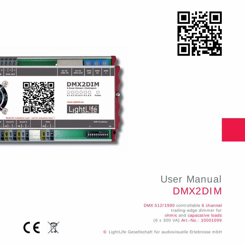
DMX 512/1990 controllable 6 channeltrailing-edge dimmer for
ohmic and capacative loads(6 x 300 VA) Art.-No.: 10001099
Technical Specifications
Important note!
PowerNumber of channelsFrequencyCurrent Consumption
Maximum switching lossesShut-down speedTotal power dissipationEfficiencyConnection terminalFanProtection classOvervoltage categoryIP protection classAmbient temperatureConnection typeFuse
Dimensions L x W x HWeight
230 VAC6 x 300 VA / 230 VAC (3 x 600 VA)40 Hz - 70 Hz (usual 50 Hz/60 Hz)approx. 150 mA without load (apparent current 230 VAC without load), Power consumption without load approx. 4 W, Inductive power consumption without load approx. 35 VA6 x 12 mW (66 mW)approx. 34 µs28 W (6 x 300W load, 230 VAC)98,5 % (at full load)Cross section of 0.5 mm² bis 2.5 mm²Noise @ 1m 19 dB (A)12IP20max. 40 degree celsius at full loadYexternally via line circuit breaker 10 A - 16 A(Characteristic B, maximum of 5 Dimmer per line circuit breaker)212 x 105 x 68 mm0,8 kg
The main electrical input of the dimmer has NO Fuse. It is only required to operate the dimmer with an external fuse. In addition, a circuit breaker with a maximum of 16 A must be provided (Characteristic B).
Selection of dimmer curvesMiscellaneous and troubleshooting
Installation of the load circuitChannel bundle
Thank you for purchasing our DMX2DIM dimmer. We appreciate your trust at this early stage and wish you a successful installation.
Ex-works each DMX2DIM dimmer is labeled with a QR Code. This QR Code directs you directly to the online user manual. We strongly recommend to exchange the standard Code with your own QR Code. Thus, in the event of fault you have direct access to the system for
troubleshooting - even on the weekends.
3
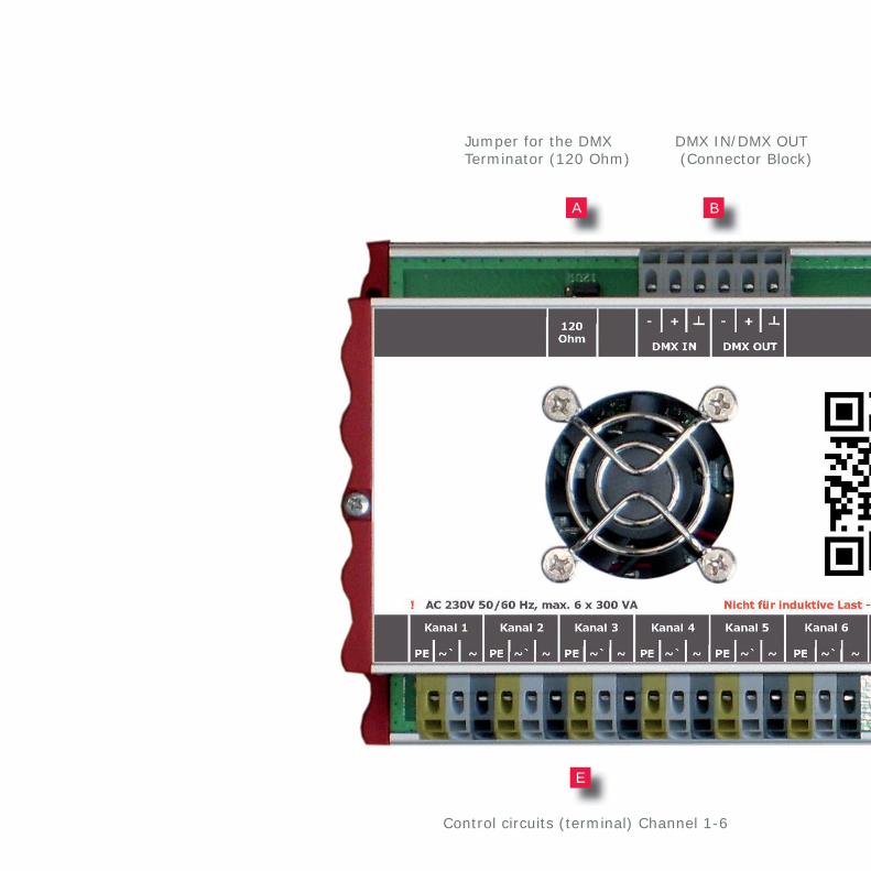
DMX IN/DMX OUT (Connector Block)
Control circuits (terminal) Channel 1-6
Jumper for the DMX Terminator (120 Ohm)
E
BA
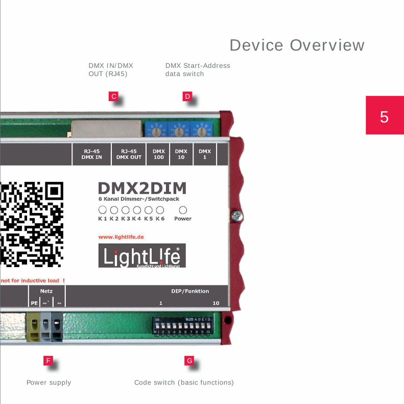
DMX IN/DMX OUT (RJ45)
DMX Start-Address data switch
Code switch (basic functions)Power supply
Device Overview
GF
DC
5
The LightLife DMX2DIM is a 6 Channel Dimmer for Din Rail mounting.
The dimensions of the dimmer fit to 12 TE DB. To ensure enough cooling, you might adjust the cover of the housing.
The mounting depth has to be at least 48 mm (distance from Din Rail to Cover). The DMX interface handles USITT DMX 512/1990 with 3 or 6 channels. You cannot use the dimmer for inductive loads (for example conventional ballast).
The maximal ohmic or capacative work load for the trailing-edge dimmer is max. 1800 VA / 230 VAC. To adjust output for consumer load, two output channel can be operated simultaneously to control each 600 VA over three DMX channels. MOSFETs are being used as switching elements. You can use up to five dimmers (DMX2DIM) on a 16 A circuit breaker (Characteristic B). The ESD protected in-and outputs are electrically isolated from the CPU control. In addition to the manual addressing, the dimmer can also be operated in automatic-addressing mode.
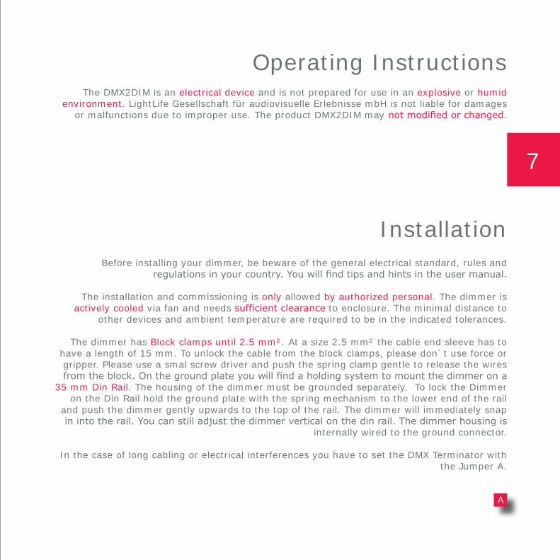
If the DMX2DIM is at the end of the DMX data line, it is possible to terminate the line via the internal 120 Ohm Jumper (A). The DMX IN-/OUTPUT is usable as a RJ45 plug (building layout according to e:cue Standard, www.ecue.de) or as terminal connection with spring terminals.
1 pcs DMX2DIM1 pcs User Manual
Shipment
General Discription
The DMX2DIM is an electrical device and is not prepared for use in an explosive or humid environment. LightLife Gesellschaft für audiovisuelle Erlebnisse mbH is not liable for damages
or malfunctions due to improper use. The product DMX2DIM may not modifi ed or changed.
Operating Instructions
Before installing your dimmer, be beware of the general electrical standard, rules and regulations in your country. You will fi nd tips and hints in the user manual.
The installation and commissioning is only allowed by authorized personal. The dimmer is actively cooled via fan and needs suffi cient clearance to enclosure. The minimal distance to
other devices and ambient temperature are required to be in the indicated tolerances.
The dimmer has Block clamps until 2.5 mm². At a size 2.5 mm² the cable end sleeve has to have a length of 15 mm. To unlock the cable from the block clamps, please don´t use force or gripper. Please use a smal screw driver and push the spring clamp gentle to release the wires from the block. On the ground plate you will fi nd a holding system to mount the dimmer on a
35 mm Din Rail. The housing of the dimmer must be grounded separately. To lock the Dimmer on the Din Rail hold the ground plate with the spring mechanism to the lower end of the rail
and push the dimmer gently upwards to the top of the rail. The dimmer will immediately snap in into the rail. You can still adjust the dimmer vertical on the din rail. The dimmer housing is
internally wired to the ground connector.
In the case of long cabling or electrical interferences you have to set the DMX Terminator with the Jumper A.
Installation
A
7
ON
OFF
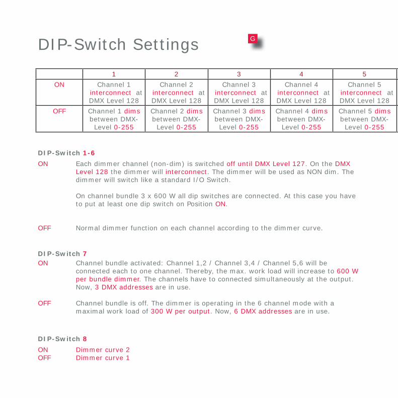
Each dimmer channel (non-dim) is switched off until DMX Level 127. On the DMX Level 128 the dimmer will interconnect. The dimmer will be used as NON dim. The dimmer will switch like a standard I/O Switch.
On channel bundle 3 x 600 W all dip switches are connected. At this case you have to put at least one dip switch on Position ON.
Normal dimmer function on each channel according to the dimmer curve.
DIP-Switch 1-6
DIP-Switch Settings
ON
OFF
Channel bundle activated: Channel 1,2 / Channel 3,4 / Channel 5,6 will be connected each to one channel. Thereby, the max. work load will increase to 600 W per bundle dimmer. The channels have to connected simultaneously at the output. Now, 3 DMX addresses are in use.
Channel bundle is off. The dimmer is operating in the 6 channel mode with a maximal work load of 300 W per output. Now, 6 DMX addresses are in use.
DIP-Switch 7
ONOFF
Dimmer curve 2 Dimmer curve 1
DIP-Switch 8
1 2 3 4 5 6 7 8 9 10
ON Channel 1 interconnect at DMX Level 128
Channel 2 interconnect at DMX Level 128
Channel 3 interconnect at DMX Level 128
Channel 4 interconnect at DMX Level 128
Channel 5 interconnect at DMX Level 128
Channel 6 interconnect at DMX Level 128
3 Channel modus at 600 W
max. workload
dimmer curve2
Auto Frequence 60 Hz
OFF Channel 1 dimsbetween DMX-Level 0-255
Channel 2 dimsbetween DMX-Level 0-255
Channel 3 dimsbetween DMX-Level 0-255
Channel 4 dimsbetween DMX-Level 0-255
Channel 5 dimsbetween DMX-Level 0-255
Channel 6 dimsbetween DMX-Level 0-255
6 Channel modus at 300 W
max. workload
dimmer curve1
Fixed frequency 50 Hz
G
ON
OFF
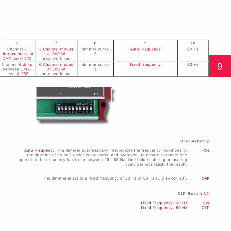
Auto Frequency. The dimmer automatically interpolates the frequency. Additionally, the duration of 50 half-waves is measured and averaged. To ensure a trouble free
operation the frequency has to be between 45 - 65 Hz. Line failures during measuring could perhaps falsify the result.
The dimmer is set to a fi xed frequency of 50 Hz or 60 Hz (Dip switch 10).
DIP-Switch 9
ONOFF
Fixed Frequency: 60 HzFixed Frequency: 50 Hz
DIP-Switch 10
1 2 3 4 5 6 7 8 9 10
ON Channel 1 interconnect at DMX Level 128
Channel 2 interconnect at DMX Level 128
Channel 3 interconnect at DMX Level 128
Channel 4 interconnect at DMX Level 128
Channel 5 interconnect at DMX Level 128
Channel 6 interconnect at DMX Level 128
3 Channel modus at 600 W
max. workload
dimmer curve2
Auto Frequence 60 Hz
OFF Channel 1 dimsbetween DMX-Level 0-255
Channel 2 dimsbetween DMX-Level 0-255
Channel 3 dimsbetween DMX-Level 0-255
Channel 4 dimsbetween DMX-Level 0-255
Channel 5 dimsbetween DMX-Level 0-255
Channel 6 dimsbetween DMX-Level 0-255
6 Channel modus at 300 W
max. workload
dimmer curve1
Fixed frequency 50 Hz 9
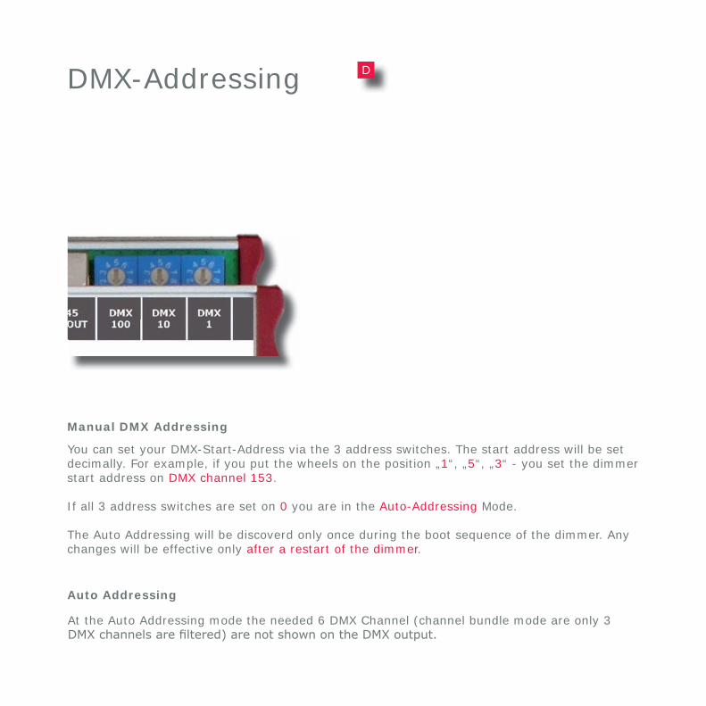
DMX-Addressing
You can set your DMX-Start-Address via the 3 address switches. The start address will be set decimally. For example, if you put the wheels on the position „1“, „5“, „3“ - you set the dimmer start address on DMX channel 153.
If all 3 address switches are set on 0 you are in the Auto-Addressing Mode.
The Auto Addressing will be discoverd only once during the boot sequence of the dimmer. Any changes will be effective only after a restart of the dimmer.
At the Auto Addressing mode the needed 6 DMX Channel (channel bundle mode are only 3 DMX channels are fi ltered) are not shown on the DMX output.
Auto Addressing
Manual DMX Addressing
D
Important: All daisy chained DMX devices must be setted on „auto address“ mode.
DMX of the lighting control
DMX of the lighting control
Address0, 0, 0
Address1, 5, 3
Address0, 0, 0
Address1, 5, 9
Example for Auto Addressing
Example for Manual DMX Addressing
11
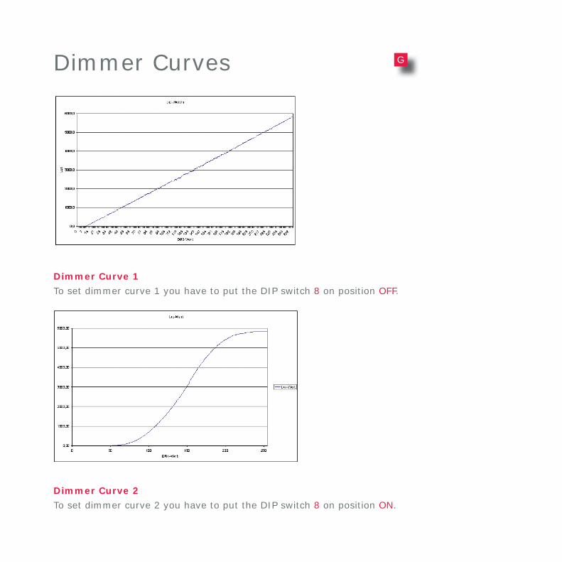
Dimmer Curves
Dimmer Curve 1
Dimmer Curve 2
To set dimmer curve 1 you have to put the DIP switch 8 on position OFF.
To set dimmer curve 2 you have to put the DIP switch 8 on position ON.
G
„Start-Up“ Test SequenceOn each start-up the DMX2DIM runs a self-test sequence. The fan will start-up shortly to check
its function. Each channel is equipped with bicolor LED (green/red). The Green LED is showing the actually load in coherence to the DMX signal.
Fan controlAccording to the compact dimmer housing and the resulting power loss the DMX Dimmer
needs an active Cooling System realized with a fan. The fan only turns on if required. Additionally, temperature within the housing is measured. If the dimmer temperature rises
above 50 Degree Celsius the fan will be turned on. If temperature is below 40 degrees celsius the fan will be turned off. Therefore, the hysteresis has a temperature of 10 degrees celsius.
Emergency ShutdownTo avoid any damages on the dimmer caused by over heating, the DMX dimmer has an
“emergency shutdown“ sequence. If the PCB temperature rises above 70 Degree Celsius, the DMX dimmer will locked and all output channels will be shut down. When the PCB cools down below 55 degree celsius, the dimmer will unlock all channels again. Therefore, the hysteresis
has a temperature of 15 degrees celsius. During the Emergency Shut down Sequence the RED LED will be on!
Short Circuit ProtectionThe dimmer is equipped with an internal electronic fuse which protects the dimmer on the
outputs against overload and short circuit. If there is an overload or short circuit on a single output channel, the dimmer will shut down and lock this channel immediately. To unlock these
channels you have to reboot the cimmer again.
Limited WarrantyWe guarantee this product for 24 months.
Miscellaneous and Trouble-Shooting
13
PowerK 1 K 2 K 3 K 4 K 5 K 6
www.lightlife.de
DMX 1
DMX 10
DMX 100
RJ-45 DMX IN
RJ-45 DMX OUT
120Ohm
DMX2DIM
Kanal 1
! AC 230V 50/60 Hz, max. 6 x 300 VA Nicht für induktive Last - not for inductive load !
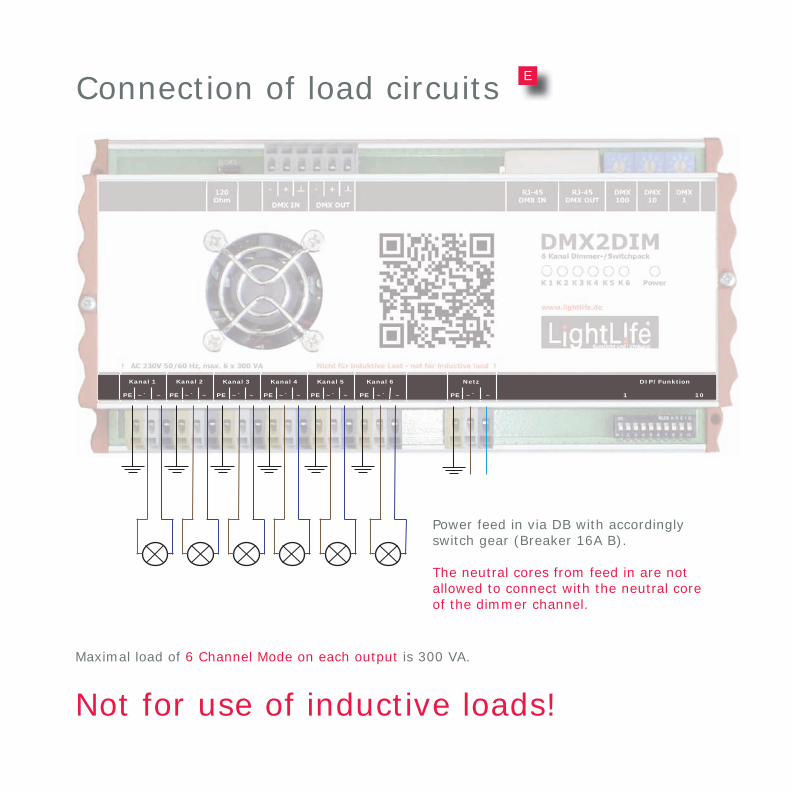
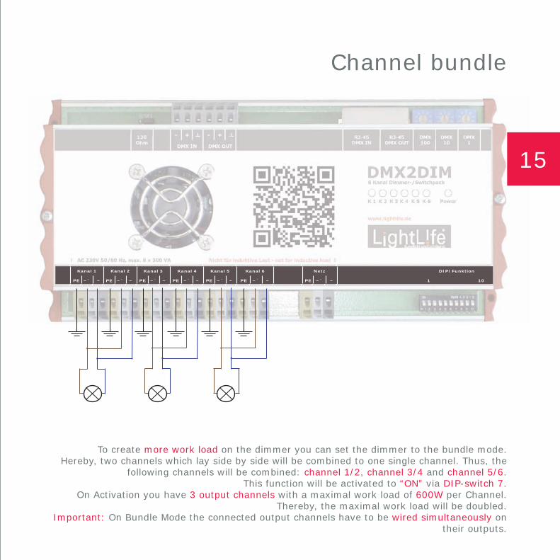
To create more work load on the dimmer you can set the dimmer to the bundle mode.Hereby, two channels which lay side by side will be combined to one single channel. Thus, the
following channels will be combined: channel 1/2, channel 3/4 and channel 5/6.This function will be activated to “ON” via DIP-switch 7.
On Activation you have 3 output channels with a maximal work load of 600W per Channel.Thereby, the maximal work load will be doubled.
Important: On Bundle Mode the connected output channels have to be wired simultaneously on their outputs.