Montage- und Betriebsanleitung / Assembly and Operating manual L-39
2
Lieber Kunde, vielen Dank für den Kauf des L-39 Modellflugzeugs. Es sind nur sehr wenige Vorbereitungsarbeiten erforderlich, um dieses Modell flugbereit zu machen. Um Ihr neues Modell sicher zu betreiben, ist es wichtig, dass Sie alle Anweisungen und Sicherheitsinformationen Ihres Modells lesen, bevor Sie es zum ersten Mal fliegen. Die Abbildungen in diesem Handbuch zeigen das Modell mit werkseitig angebrachten Aufklebern. Das Powersystem Das Modell wird von einem bürstenlosen Außenläufer-Motor und einem Impeller angetrieben, die beide werkseitig in der PNP-Version installiert sind. Der Motor ist an den elektronischen Drehzahlregler (ESC) angeschlossen, der werkseitig in der PNP-Version kalibriert ist. Sie müssen lediglich den Li-Po-Akku gemäß den Sicherheitshinweisen aufladen und den Akku an den elektronischen Geschwindigkeitsregler anschließen. Das Fernsteuerungssystem Um L-39 fliegen zu können, benötigen Sie ein Funksteuerungssystem mit mindestens vier Kanälen. Es werden 2,4-GHz-Funksysteme empfohlen.
Die Servos für die Querruder, Seitenruder und die Höhenruder sind werkseitig installiert. Die Stromversorgung für den Empfänger erfolgt über das integrierte BEC-System des ESC. Der elektronische Drehzahlregler befindet sich im Rumpf vor dem Impeller. Um die Systeme des Modells zu überprüfen, stellen Sie zuerst die Servos auf Neutral, indem Sie die Trimmung auf Neutral stellen und den Gashebel und die Gas-Trimmung auf der niedrigsten Position belassen. Wenn Sie das Modell fliegen möchten, stellen Sie immer sicher, dass der Sender eingeschaltet ist. Bewegen Sie den Gashebel in die unterste Position. Schließen Sie dann den Akku an den ESC an. Wenn Sie den Flug beendet haben, führen Sie diesen Vorgang in umgekehrter Reihenfolge durch. Zuerst den Akku abklemmen, dann den Sender ausschalten. Klebeverbindungen mit geeigneten Klebstoffen Schaumsicheres Epoxidharz wird empfohlen und ist in den meisten renommierten Modellgeschäften erhältlich. Probieren Sie alle Teile „trocken“ aus, bevor Sie Klebstoff auftragen. Befolgen Sie die vom Klebstoffhersteller empfohlene
Aushärtezeit. Lassen Sie den Kleber vollständig aushärten, bis die Verbindung belastet werden kann. Das Set beinhaltet Rumpf mit Motor, elektronischer Geschwindigkeitsregler (ESC) Cockpit-Haube. Tragfläche mit Querruderservos Seitenruder Zubehör Brushless ESC
Montage- und Betriebsanleitung / Assembly and Operating manual L-39
3
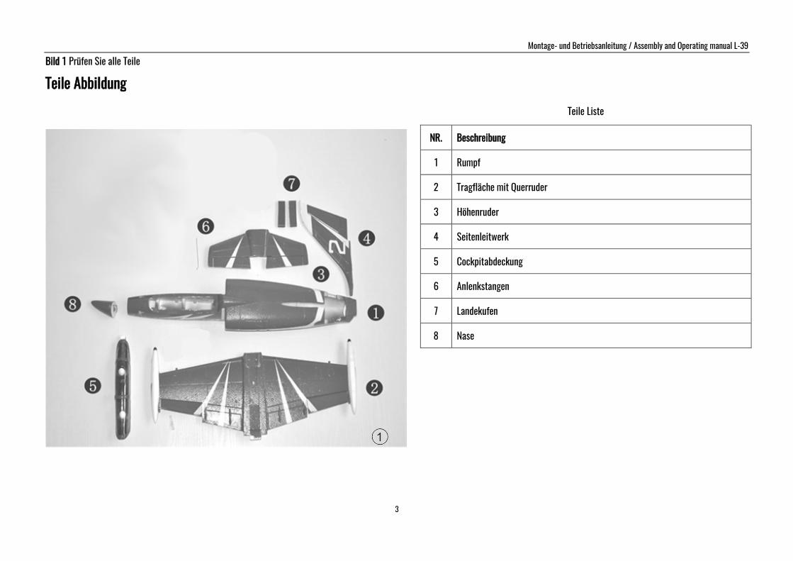
Bild 1 Prüfen Sie alle Teile
Teile Abbildung
Teile Liste
NR. Beschreibung
1 Rumpf
2 Tragfläche mit Querruder
3 Höhenruder
4 Seitenleitwerk
5 Cockpitabdeckung
6 Anlenkstangen
7 Landekufen
8 Nase
Montage- und Betriebsanleitung / Assembly and Operating manual L-39
4
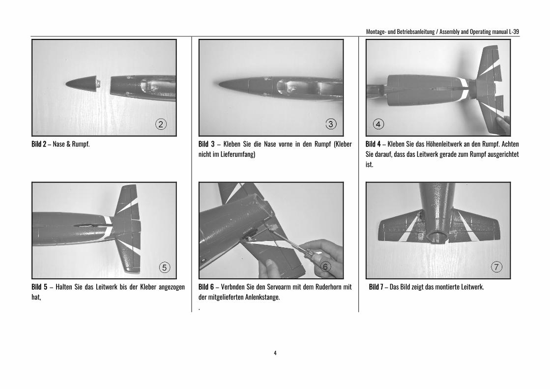
Bild 2 – Nase & Rumpf.
Bild 5 – Halten Sie das Leitwerk bis der Kleber angezogen hat,
Bild 3 – Kleben Sie die Nase vorne in den Rumpf (Kleber nicht im Lieferumfang)
Bild 6 – Verbnden Sie den Servoarm mit dem Ruderhorn mit der mitgelieferten Anlenkstange. .
Bild 4 – Kleben Sie das Höhenleitwerk an den Rumpf. Achten Sie darauf, dass das Leitwerk gerade zum Rumpf ausgerichtet ist.
Bild 7 – Das Bild zeigt das montierte Leitwerk.
Montage- und Betriebsanleitung / Assembly and Operating manual L-39
5
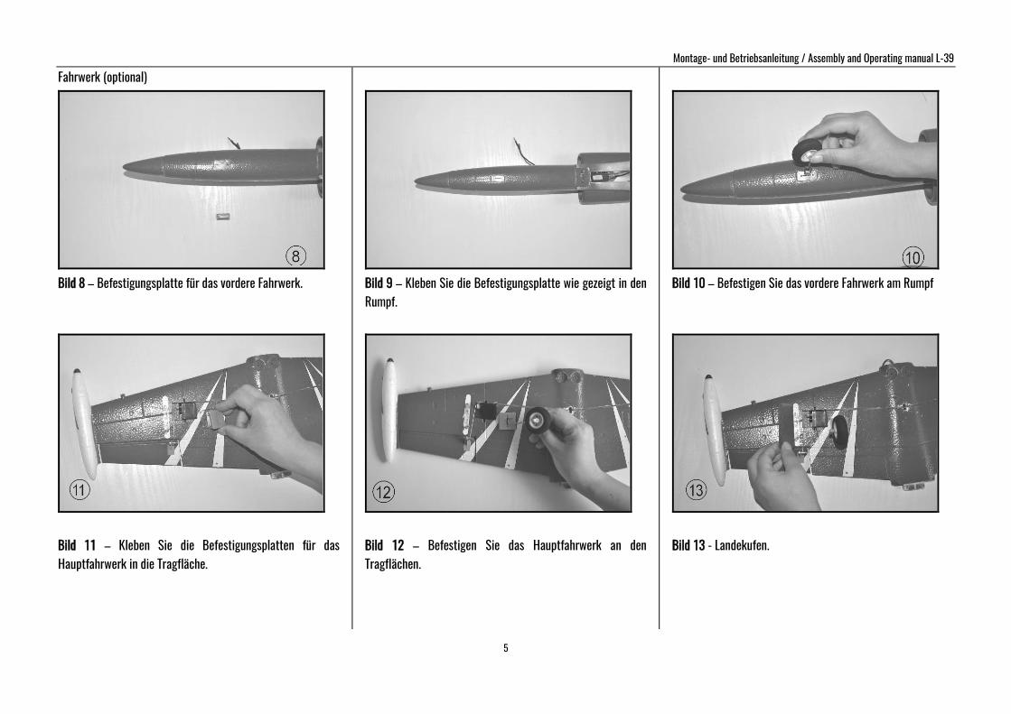
Fahrwerk (optional)
Bild 8 – Befestigungsplatte für das vordere Fahrwerk.
Bild 11 – Kleben Sie die Befestigungsplatten für das Hauptfahrwerk in die Tragfläche.
Bild 9 – Kleben Sie die Befestigungsplatte wie gezeigt in den Rumpf.
Bild 12 – Befestigen Sie das Hauptfahrwerk an den Tragflächen.
Bild 10 – Befestigen Sie das vordere Fahrwerk am Rumpf
Bild 13 - Landekufen.
Montage- und Betriebsanleitung / Assembly and Operating manual L-39
6
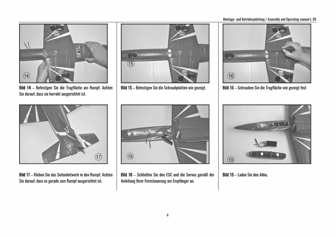
Bild 14 – Befestigen Sie die Tragfläche am Rumpf. Achten Sie darauf, dass sie korrekt ausgerichtet ist.
Bild 17 – Kleben Sie das Seitenleitwerk in den Rumpf. Achten Sie darauf, dass es gerade zum Rumpf ausgerichtet ist.
Bild 15 – Befestigen Sie die Schraubplatten wie gezeigt.
Bild 18 – Schließen Sie den ESC und die Servos gemäß der Anleitung Ihrer Fernsteuerung am Empfänger an.
Bild 16 – Schrauben Sie die Tragfläche wie gezeigt fest
Bild 19 – Laden Sie den Akku.
Montage- und Betriebsanleitung / Assembly and Operating manual L-39
7
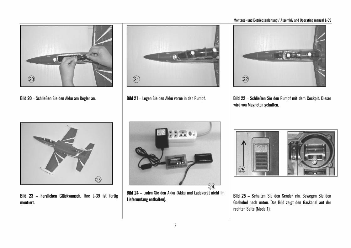
Bild 20 – Schließen Sie den Akku am Regler an.
Bild 23 – herzlichen Glückwunsch. Ihre L-39 ist fertig montiert.
Bild 21 – Legen Sie den Akku vorne in den Rumpf.
Bild 24 – Laden Sie den Akku (Akku und Ladegerät nicht im Lieferumfang enthalten).
Bild 22 – Schließen Sie den Rumpf mit dem Cockpit. Dieser wird von Magneten gehalten.
Bild 25 – Schalten Sie den Sender ein. Bewegen Sie den Gashebel nach unten. Das Bild zeigt den Gaskanal auf der rechten Seite (Mode 1).
Montage- und Betriebsanleitung / Assembly and Operating manual L-39
8
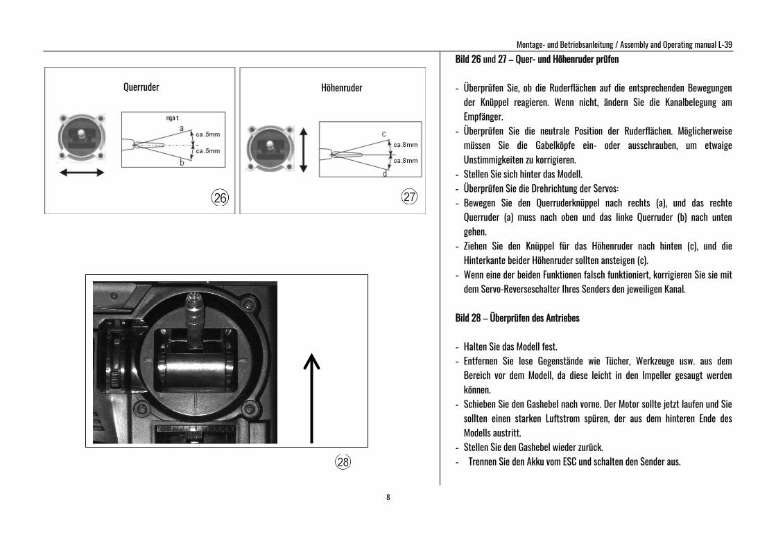
Bild 26 und 27 – Quer- und Höhenruder prüfen - Überprüfen Sie, ob die Ruderflächen auf die entsprechenden Bewegungen
der Knüppel reagieren. Wenn nicht, ändern Sie die Kanalbelegung am Empfänger.
- Überprüfen Sie die neutrale Position der Ruderflächen. Möglicherweise müssen Sie die Gabelköpfe ein- oder ausschrauben, um etwaige Unstimmigkeiten zu korrigieren.
- Stellen Sie sich hinter das Modell. - Überprüfen Sie die Drehrichtung der Servos: - Bewegen Sie den Querruderknüppel nach rechts (a), und das rechte
Querruder (a) muss nach oben und das linke Querruder (b) nach unten gehen.
- Ziehen Sie den Knüppel für das Höhenruder nach hinten (c), und die Hinterkante beider Höhenruder sollten ansteigen (c).
- Wenn eine der beiden Funktionen falsch funktioniert, korrigieren Sie sie mit dem Servo-Reverseschalter Ihres Senders den jeweiligen Kanal.
Bild 28 – Überprüfen des Antriebes - Halten Sie das Modell fest. - Entfernen Sie lose Gegenstände wie Tücher, Werkzeuge usw. aus dem
Bereich vor dem Modell, da diese leicht in den Impeller gesaugt werden können.
- Schieben Sie den Gashebel nach vorne. Der Motor sollte jetzt laufen und Sie sollten einen starken Luftstrom spüren, der aus dem hinteren Ende des Modells austritt.
- Stellen Sie den Gashebel wieder zurück. - Trennen Sie den Akku vom ESC und schalten den Sender aus.
Querruder Höhenruder
Montage- und Betriebsanleitung / Assembly and Operating manual L-39
9
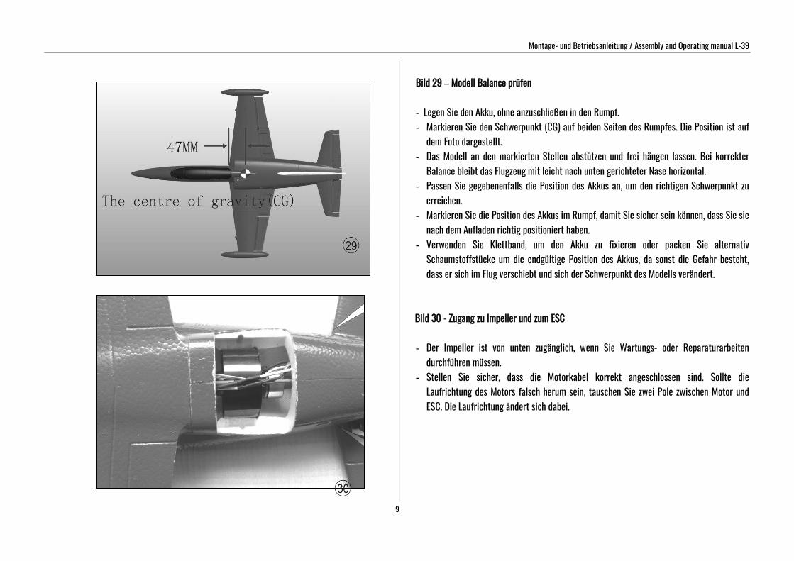
Bild 29 – Modell Balance prüfen
- Legen Sie den Akku, ohne anzuschließen in den Rumpf. - Markieren Sie den Schwerpunkt (CG) auf beiden Seiten des Rumpfes. Die Position ist auf
dem Foto dargestellt. - Das Modell an den markierten Stellen abstützen und frei hängen lassen. Bei korrekter
Balance bleibt das Flugzeug mit leicht nach unten gerichteter Nase horizontal. - Passen Sie gegebenenfalls die Position des Akkus an, um den richtigen Schwerpunkt zu
erreichen. - Markieren Sie die Position des Akkus im Rumpf, damit Sie sicher sein können, dass Sie sie
nach dem Aufladen richtig positioniert haben. - Verwenden Sie Klettband, um den Akku zu fixieren oder packen Sie alternativ
Schaumstoffstücke um die endgültige Position des Akkus, da sonst die Gefahr besteht, dass er sich im Flug verschiebt und sich der Schwerpunkt des Modells verändert.
Bild 30 - Zugang zu Impeller und zum ESC - Der Impeller ist von unten zugänglich, wenn Sie Wartungs- oder Reparaturarbeiten
durchführen müssen. - Stellen Sie sicher, dass die Motorkabel korrekt angeschlossen sind. Sollte die
Laufrichtung des Motors falsch herum sein, tauschen Sie zwei Pole zwischen Motor und ESC. Die Laufrichtung ändert sich dabei.
Montage- und Betriebsanleitung / Assembly and Operating manual L-39
10
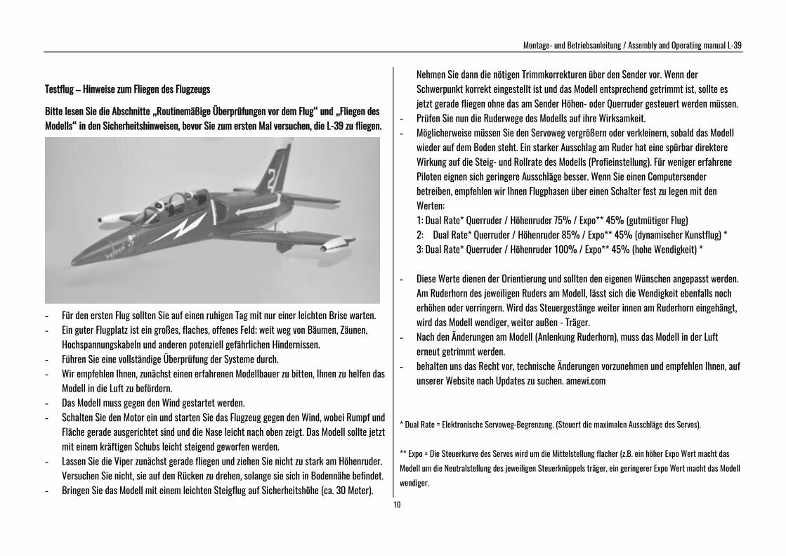
Testflug – Hinweise zum Fliegen des Flugzeugs Bitte lesen Sie die Abschnitte „Routinemäßige Überprüfungen vor dem Flug“ und „Fliegen des Modells“ in den Sicherheitshinweisen, bevor Sie zum ersten Mal versuchen, die L-39 zu fliegen.
- Für den ersten Flug sollten Sie auf einen ruhigen Tag mit nur einer leichten Brise warten. - Ein guter Flugplatz ist ein großes, flaches, offenes Feld; weit weg von Bäumen, Zäunen,
Hochspannungskabeln und anderen potenziell gefährlichen Hindernissen. - Führen Sie eine vollständige Überprüfung der Systeme durch. - Wir empfehlen Ihnen, zunächst einen erfahrenen Modellbauer zu bitten, Ihnen zu helfen das
Modell in die Luft zu befördern. - Das Modell muss gegen den Wind gestartet werden. - Schalten Sie den Motor ein und starten Sie das Flugzeug gegen den Wind, wobei Rumpf und
Fläche gerade ausgerichtet sind und die Nase leicht nach oben zeigt. Das Modell sollte jetzt mit einem kräftigen Schubs leicht steigend geworfen werden.
- Lassen Sie die Viper zunächst gerade fliegen und ziehen Sie nicht zu stark am Höhenruder. Versuchen Sie nicht, sie auf den Rücken zu drehen, solange sie sich in Bodennähe befindet.
- Bringen Sie das Modell mit einem leichten Steigflug auf Sicherheitshöhe (ca. 30 Meter).
Nehmen Sie dann die nötigen Trimmkorrekturen über den Sender vor. Wenn der Schwerpunkt korrekt eingestellt ist und das Modell entsprechend getrimmt ist, sollte es jetzt gerade fliegen ohne das am Sender Höhen- oder Querruder gesteuert werden müssen.
- Prüfen Sie nun die Ruderwege des Modells auf ihre Wirksamkeit. - Möglicherweise müssen Sie den Servoweg vergrößern oder verkleinern, sobald das Modell
wieder auf dem Boden steht. Ein starker Ausschlag am Ruder hat eine spürbar direktere Wirkung auf die Steig- und Rollrate des Modells (Profieinstellung). Für weniger erfahrene Piloten eignen sich geringere Ausschläge besser. Wenn Sie einen Computersender betreiben, empfehlen wir Ihnen Flugphasen über einen Schalter fest zu legen mit den Werten: 1: Dual Rate* Querruder / Höhenruder 75% / Expo** 45% (gutmütiger Flug) 2: Dual Rate* Querruder / Höhenruder 85% / Expo** 45% (dynamischer Kunstflug) * 3: Dual Rate* Querruder / Höhenruder 100% / Expo** 45% (hohe Wendigkeit) *
- Diese Werte dienen der Orientierung und sollten den eigenen Wünschen angepasst werden. Am Ruderhorn des jeweiligen Ruders am Modell, lässt sich die Wendigkeit ebenfalls noch erhöhen oder verringern. Wird das Steuergestänge weiter innen am Ruderhorn eingehängt, wird das Modell wendiger, weiter außen - Träger.
- Nach den Änderungen am Modell (Anlenkung Ruderhorn), muss das Modell in der Luft erneut getrimmt werden.
- behalten uns das Recht vor, technische Änderungen vorzunehmen und empfehlen Ihnen, auf unserer Website nach Updates zu suchen. amewi.com
* Dual Rate = Elektronische Servoweg-Begrenzung. (Steuert die maximalen Ausschläge des Servos). ** Expo = Die Steuerkurve des Servos wird um die Mittelstellung flacher (z.B. ein höher Expo Wert macht das Modell um die Neutralstellung des jeweiligen Steuerknüppels träger, ein geringerer Expo Wert macht das Modell wendiger.
Montage- und Betriebsanleitung / Assembly and Operating Manual L-39
11
Dear customer, Congratulations on your choice of a factory-assembled model aircraft from the amewi and thank you for placing your trust in us. Very little preparation work is required to get this model ready to fly. To operate your new model safely it is important that you read through all of the instructions and safety information included with your model, before you fly it for the first time. The illustrations in this manual show the Red version of the model with factory applied decals. The power system The model is powered by a brushless outrunner motor and ducted fan, both of which are factory-installed on the Ready-To-Fly version. The motor is connected to the electronic speed controller which is factory calibrated on the Ready-To-Fly version. All that is required is to charge the Li-Po battery, following the safety instructions, and connect battery to the electronic speed controller. The radio control system
To fly the L39 you will need a radio control system with at least four channels. 2.4GHz radios systems are recommended, like the unit included with our deluxe version. The servos for the ailerons and the elevators are factory-installed. The power for the receiver is drawn from the electronic speed controller’s integral BEC system. The electronic speed controller is located inside of the fuselage, in front of the ducted fan. To check the model’s operating systems, first set the control surface servos to neutral, with the transmitter sticks and trims at centre. When you wish to fly the model, always make sure the transmitter is in the “OFF” position. Move the throttle stick to the “OFF” position as well. Then connect the flight battery to the electronic speed controller. Switch off in the reverse order: disconnect the battery from the electronic speed controller first, and then switch off the transmitter. Glued joints, suitable adhesives Foam safe epoxy is recommended and available from most reputable model retail shops.
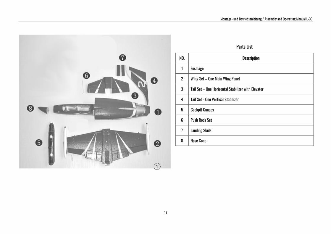
Trial-fit all parts “dry” before applying glue. Follow the recommended curing time suggested by the glue manufacturer. Allow the glue to fully cure (harden) to the point where the joint can be placed under stress. Kit contents Fuselage, with motor, electronic speed controller and servo Clear canopy and cockpit Main wing panels with ailerons and servo Left / right tail plane panels with elevators and vertical stabilizer Accessories 1 x Li-Po battery, 3s 850mAh 20C 1 x 20A Brushless ESC (Electronic Speed Controller) Fig. 1 Open the box and check all the parts.
Parts Illustration
Montage- und Betriebsanleitung / Assembly and Operating Manual L-39
12
Parts List
NO. Description
1 Fuselage
2 Wing Set – One Main Wing Panel
3 Tail Set – One Horizontal Stabilizer with Elevator
4 Tail Set - One Vertical Stabilizer
5 Cockpit Canopy
6 Push Rods Set
7 Landing Skids
8 Nose Cone
Montage- und Betriebsanleitung / Assembly and Operating Manual L-39
13
Fig. 2 - Locate the fuselage and nose cone.
Fig. 5 - Remove any excess glue and hold in position until glue sets. The photo shows the finished view.
Fig. 3 - Glue the nose to the front of fuselage (glue not included).
Fig. 6 - Connect the push rods to the elevator servo arm and control horn. .
Fig. 4 - Glue the horizontal stabilizers to the slots at the rear of the fuselage (glue not included).
Fig. 7 - Photo shows the finished view after elevator push rods are assembled.
Montage- und Betriebsanleitung / Assembly and Operating Manual L-39
14
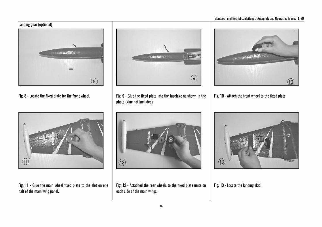
Landing gear (optional)
Fig. 8 - Locate the fixed plate for the front wheel.
Fig. 11 - Glue the main wheel fixed plate to the slot on one half of the main wing panel.
Fig. 9 - Glue the fixed plate into the fuselage as shown in the photo (glue not included).
Fig. 12 - Attached the rear wheels to the fixed plate units on each side of the main wings.
Fig. 10 - Attach the front wheel to the fixed plate
Fig. 13 - Locate the landing skid.
Montage- und Betriebsanleitung / Assembly and Operating Manual L-39
15
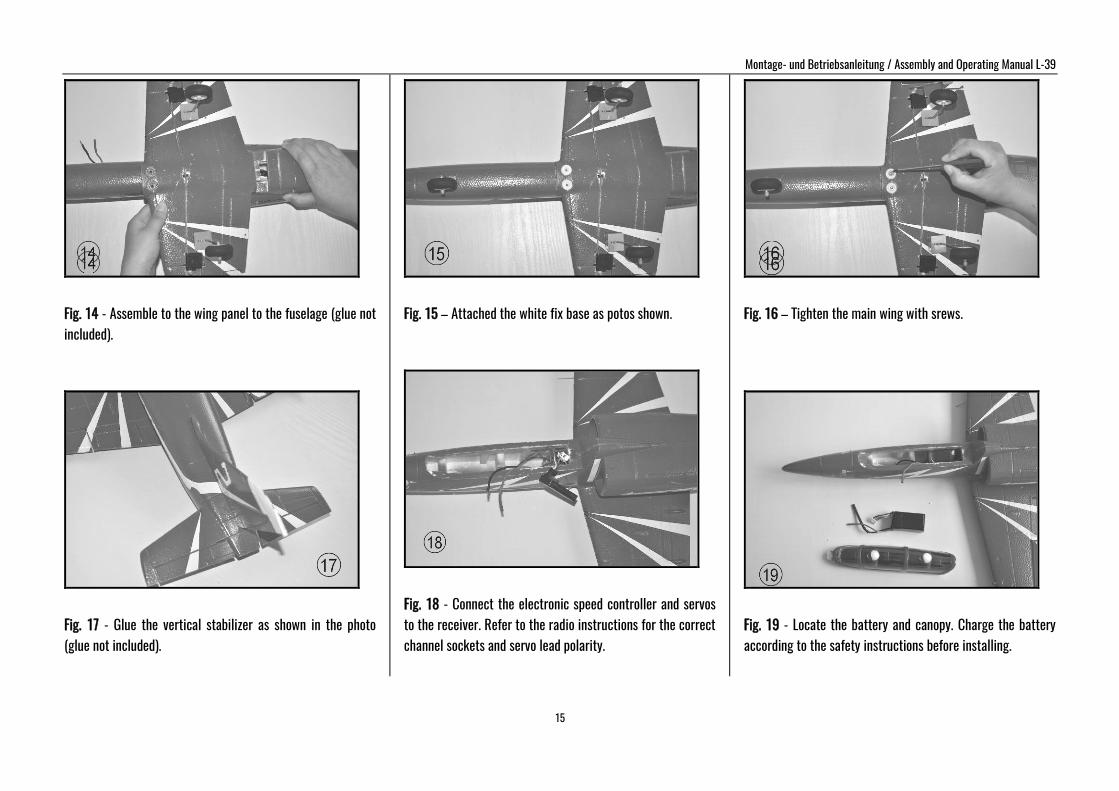
Fig. 14 - Assemble to the wing panel to the fuselage (glue not included).
Fig. 17 - Glue the vertical stabilizer as shown in the photo (glue not included).
Fig. 15 – Attached the white fix base as potos shown.
Fig. 18 - Connect the electronic speed controller and servos to the receiver. Refer to the radio instructions for the correct channel sockets and servo lead polarity.
Fig. 16 – Tighten the main wing with srews.
Fig. 19 - Locate the battery and canopy. Charge the battery according to the safety instructions before installing.
Montage- und Betriebsanleitung / Assembly and Operating Manual L-39
16
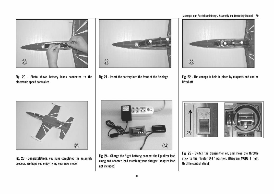
Fig. 20 - Photo shows battery leads connected to the electronic speed controller.
Fig. 23 - Congratulations, you have completed the assembly process. We hope you enjoy flying your new model!
Fig. 21 - Insert the battery into the front of the fuselage.
Fig. 24 - Charge the flight battery; connect the Equalizer lead using and adapter lead matching your charger (adapter lead not included)
Fig. 22 - The canopy is held in place by magnets and can be lifted off.
Fig. 25 - Switch the transmitter on, and move the throttle stick to the “Motor OFF” position. (Diagram MODE 1 right throttle control stick)
Montage- und Betriebsanleitung / Assembly and Operating Manual L-39
17
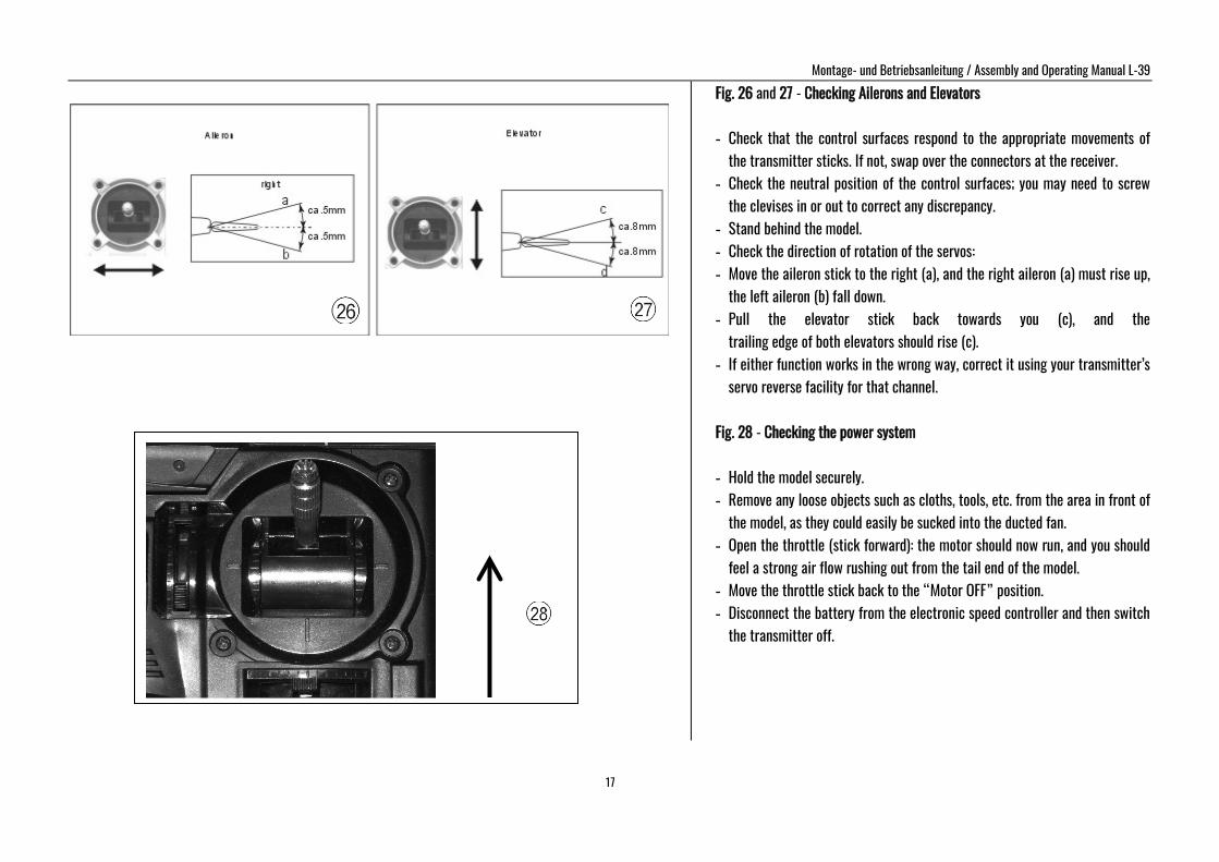
Fig. 26 and 27 - Checking Ailerons and Elevators - Check that the control surfaces respond to the appropriate movements of
the transmitter sticks. If not, swap over the connectors at the receiver. - Check the neutral position of the control surfaces; you may need to screw
the clevises in or out to correct any discrepancy. - Stand behind the model. - Check the direction of rotation of the servos: - Move the aileron stick to the right (a), and the right aileron (a) must rise up,
the left aileron (b) fall down. - Pull the elevator stick back towards you (c), and the
trailing edge of both elevators should rise (c). - If either function works in the wrong way, correct it using your transmitter’s
servo reverse facility for that channel.
Fig. 28 - Checking the power system - Hold the model securely. - Remove any loose objects such as cloths, tools, etc. from the area in front of
the model, as they could easily be sucked into the ducted fan. - Open the throttle (stick forward): the motor should now run, and you should
feel a strong air flow rushing out from the tail end of the model. - Move the throttle stick back to the “Motor OFF” position. - Disconnect the battery from the electronic speed controller and then switch
the transmitter off.
Montage- und Betriebsanleitung / Assembly and Operating Manual L-39
18
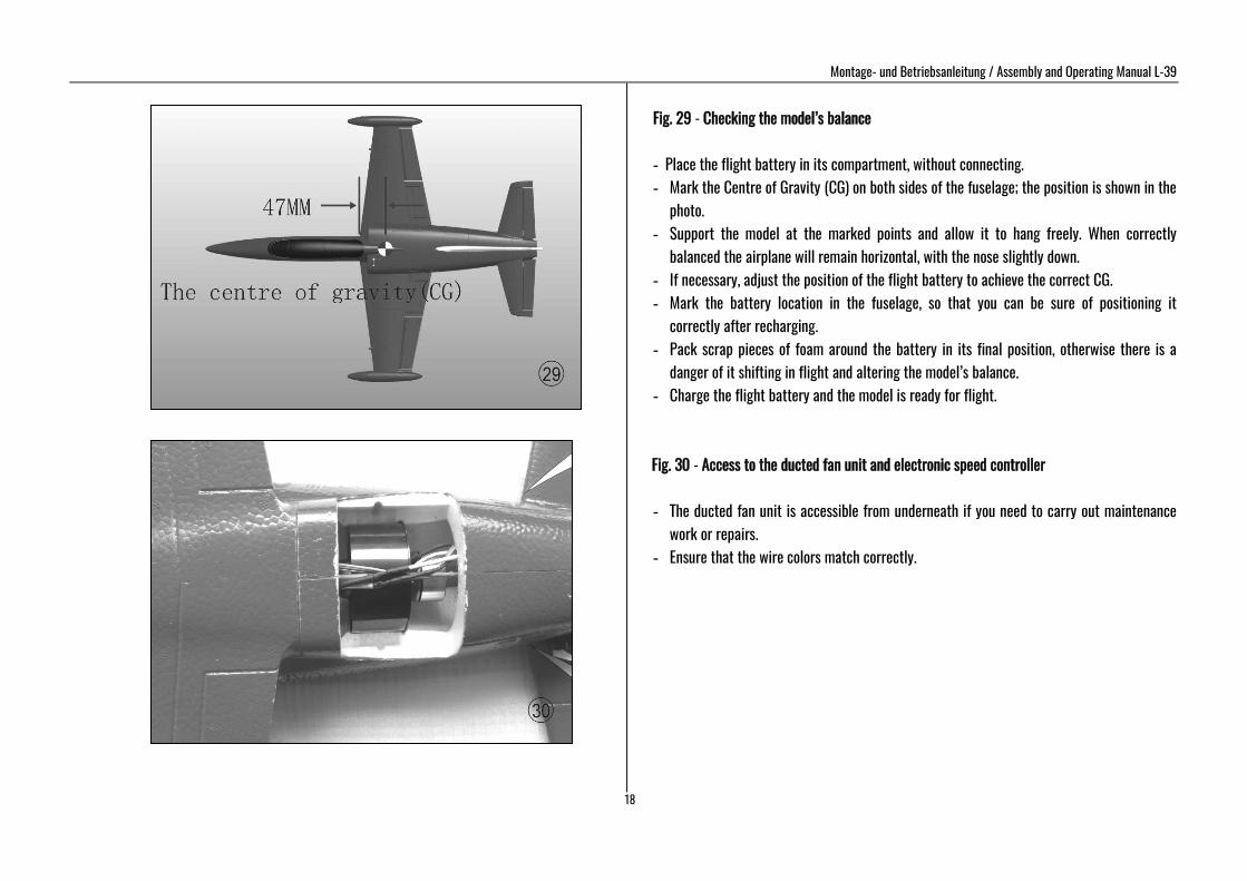
Fig. 29 - Checking the model’s balance
- Place the flight battery in its compartment, without connecting. - Mark the Centre of Gravity (CG) on both sides of the fuselage; the position is shown in the
photo. - Support the model at the marked points and allow it to hang freely. When correctly
balanced the airplane will remain horizontal, with the nose slightly down. - If necessary, adjust the position of the flight battery to achieve the correct CG. - Mark the battery location in the fuselage, so that you can be sure of positioning it
correctly after recharging. - Pack scrap pieces of foam around the battery in its final position, otherwise there is a
danger of it shifting in flight and altering the model’s balance. - Charge the flight battery and the model is ready for flight.
Fig. 30 - Access to the ducted fan unit and electronic speed controller - The ducted fan unit is accessible from underneath if you need to carry out maintenance
work or repairs. - Ensure that the wire colors match correctly.
Montage- und Betriebsanleitung / Assembly and Operating Manual L-39
19
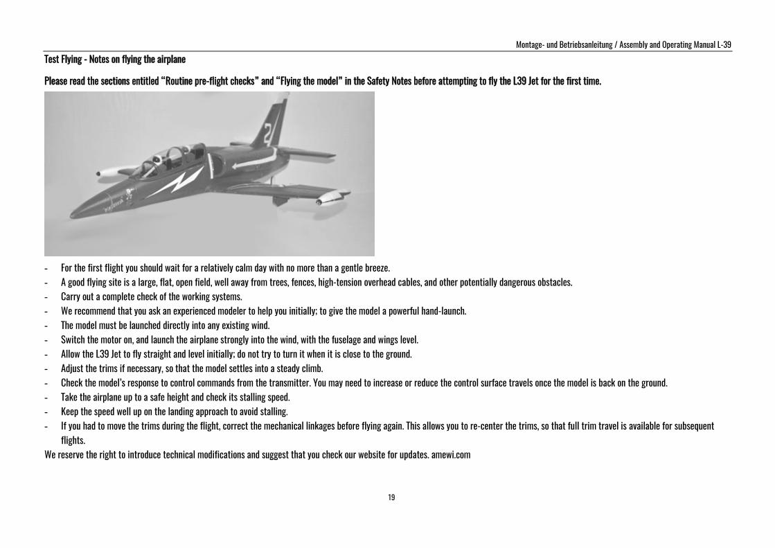
Test Flying - Notes on flying the airplane Please read the sections entitled “Routine pre-flight checks” and “Flying the model” in the Safety Notes before attempting to fly the L39 Jet for the first time.
- For the first flight you should wait for a relatively calm day with no more than a gentle breeze. - A good flying site is a large, flat, open field, well away from trees, fences, high-tension overhead cables, and other potentially dangerous obstacles. - Carry out a complete check of the working systems. - We recommend that you ask an experienced modeler to help you initially; to give the model a powerful hand-launch. - The model must be launched directly into any existing wind. - Switch the motor on, and launch the airplane strongly into the wind, with the fuselage and wings level. - Allow the L39 Jet to fly straight and level initially; do not try to turn it when it is close to the ground. - Adjust the trims if necessary, so that the model settles into a steady climb. - Check the model’s response to control commands from the transmitter. You may need to increase or reduce the control surface travels once the model is back on the ground. - Take the airplane up to a safe height and check its stalling speed. - Keep the speed well up on the landing approach to avoid stalling. - If you had to move the trims during the flight, correct the mechanical linkages before flying again. This allows you to re-center the trims, so that full trim travel is available for subsequent
flights. We reserve the right to introduce technical modifications and suggest that you check our website for updates. amewi.com