64
Kompakt-Wärmezähler Typ Compact Heat Meter Type Contatore di calore compatto Modello Calorímetro compacto Tipo HYDROCAL G 21 Quickstart
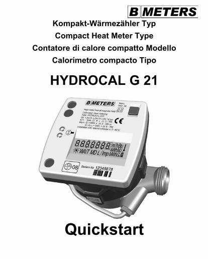
Kompakt-Wärmezähler Typ
Compact Heat Meter Type
Contatore di calore compatto Modello
Calorímetro compacto Tipo
HYDROCAL G 21
Quickstart
2
© by BMeters srl Für diese Dokumentation beansprucht BMeters srl Urheberrechtsschutz. Diese Dokumentation darf ohne vorherige schriftliche Zustimmung der Firma BMeters srl weder abgeändert, erweitert, vervielfältigt, in einem elektronischen System erfasst oder an Dritte weitergegeben werden. Titel: Quickstart Wärmezähler Typ BMETERS HYDROCAL G 21 - KUGELHAHN Dateiname: 190 477MU – HYDROCAL G 21 - Quickstart.doc Ausgabe: 20.05.2008 / V 1.1 Haftungsausschluss! BMeters srl haftet generell nicht bei Weiterveräußerung in Länder, für die keine aktuellen Versionen oder Zulassungen für dieses Produkt vorliegen. Design- und Geräteänderungen vorbehalten.
3
© by BMeters srl This documentation is protected by copyright owned by BMeters srl. It is prohibited to duplicate or copy, alter or extend this documentation without prior written consent by BMeters srl, and it is not permissible to store this documentation in an electronic retrieval system nor to make it available to third parties. Title: Compact Heat Meter Type BMETERS HYDROCAL G 21 File name: 190 477MU – HYDROCAL G 21 - Quickstart.doc Date of issue: 20.05.2008 / V 1.1 Disclaimer! In general, BMeters srl cannot be held liable when its products are sold in countries having no current versions or approvals for them. Design and devices are subject to modifications.
GB
© by BMeters srl La BMeters srl reclama per questa documentazione la tutela mediante il diritto d‘autore. La presente documentazione non può venire modificata, ampliata, memorizzata in un sistema elettronico, riprodotta o affidata a terzi senza l’autorizzazione scritta della ditta BMeters srl. Titolo: Contatore di calore compatto Modello BMETERS HYDROCAL G 21 Nome di file: 190 477MU – HYDROCAL G1 - Quickstart.doc Data di pubblicazione: 20.05.2008 / V 1.1 Esclusione di responsabilità! La BMeters srl non risponde generalmente della rivendita in paesi nei quali non esistono versioni attuali o autorizzazioni per questo prodotto. Con riserva di apportare all’apparecchio modifiche tecniche e di design.
IT
© by BMeters srl BMeters srl reclama el derecho de autor sobre esta documentación. Quedan prohibidos la modificación, la ampliación, la reproducción, el registro en sistemas electrónicos o la cesión a terceros de esta documentación sin la previa autorización escrita de la empresa BMeters srl. Título: Calorímetro compacto Tipo BMETERS HYDROCAL G 21 Nombre del archivo: 190 477MU – HYDROCAL G 21 - Quickstart.doc Fecha de edición: 20.05.2008 / V 1.1 ¡Exención de responsabilidad! BMeters srl, en general, no se responsabiliza en caso de reventa en países en los cuales no existen versiones actuales o licencias para este producto. Queda reservado el derecho de modificar el diseño y el equipo.
ES
4
Inhalt Impressum . . . . . . . . . . . . . 2 - 3 Inhalt. . . . . . . . . . . . . . 4 - 5 Doppelkennzeichnung . . . . . . . . . . . 6 Technische Daten . . . . . . . . . . . . 7 - 21 Display . . . . . . . . . . . . . 22 - 43 Montage . . . . . . . . . . . . . 44 - 53 Interne Erweiterung M-Bus-Modul . . . . . . . . . 54 - 55 Einbauvorschläge . . . . . . . . . . . 56 - 57 Checkliste . . . . . . . . . . . . . 58 - 63 Benutzerinformationen . . . . . . . . . . . 64
5
Imprint . . . . . . . . . . . 2 - 3 Contents . . . . . . . . . . . 4 - 5 Double marking . . . . . . . . . . 6 Technical data . . . . . . . . . . 7 - 21 Display . . . . . . . . . . . 22 - 43 Mounting . . . . . . . . . . . 44 - 53 Internal module extensions M bus . . . . . . . . 54 - 55 Installation proposals . . . . . . . . . 56 - 57 Check list . . . . . . . . . . . 58 - 63 User information . . . . . . . . . . 64
GB
Annotazione di pubblicazione. . . . . . . . . 2 - 3 Indice . . . . . . . . . . . 4 - 5 Contrassegno doppio . . . . . . . . . 6 Dati tecnici . . . . . . . . . . . 7 - 21 Display . . . . . . . . . . . 22 - 43 Montaggio . . . . . . . . . . . 44 - 53 Ampliamenti modulari interni M-bus . . . . . . . 54 - 55 Proposte per l’installazione . . . . . . . . . 56 - 57 Lista di controllo . . . . . . . . . . 58 - 63 Informazioni per l’utente . . . . . . . . . 64
IT
Pie de imprenta . . . . . . . . . . 2 - 3 Contenido . . . . . . . . . . . 4 - 5 Doble señalización . . . . . . . . . 6 Datos técnicos . . . . . . . . . . 7 - 21 Pantalla . . . . . . . . . . . 22 - 43 Montaje . . . . . . . . . . . 44 - 53 Ampliaciones internas del módulo bus M . . . . . . . 54 - 55 Propuestas de instalación . . . . . . . . . 56 - 57 Lista de control . . . . . . . . . . 58 - 63 Informaciones para el usuario . . . . . . . . 64
ES
6
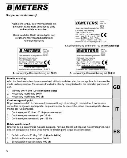
Doppelkennzeichnung!
Nach dem Einbau des Wärmezählers am Einbauort ist die nicht zutreffende Zeile
unkenntlich zu machen.
Damit wird das Gerät eindeutig für den vorgesehenen Verwendungszweck
kenntlich gemacht.
1. Kennzeichnung 30 l/h und 100 l/h (Unzulässig)
2. Notwendige Kennzeichnung auf 30 l/h
3. Notwendige Kennzeichnung auf 100 l/h
Double marking! After the heat meter has been assembled at the installation site, the not applicable line must bemade undecipherable. This makes the device clearly recognizable for the intended purpose of use.
1. Marking 30 l/h and 100 l/h (Inadmissible) 2. Necessary marking to 30 l/h 3. Necessary marking to 100 l/h
GB
Contrassegno doppio! Dopo avere installato il contatore di calore nel luogo di montaggio prestabilito, è necessario cancellare la riga non appropriata. In questo modo, l’apparecchio viene contrassegnato chiara-mente per l'uso previsto. 1. Contrassegno 30 l/h e 100 l/h (non ammesso) 2. Contrassegno necessario per 30 l/h 3. Contrassegno necessario per 100 l/h
IT
Doble señalización! Una vez que el calorímetro ha sido instalado, hay que tachar la línea que no corresponda. Con ello, en el equipo se indica únicamente la función para la que está concebido.
1. Señalización de 30 l/h y 100 l/h (inadmisible) 2. Señalización necesaria para 30 l/h 3. Señalización necesaria para 100 l/h
ES
7
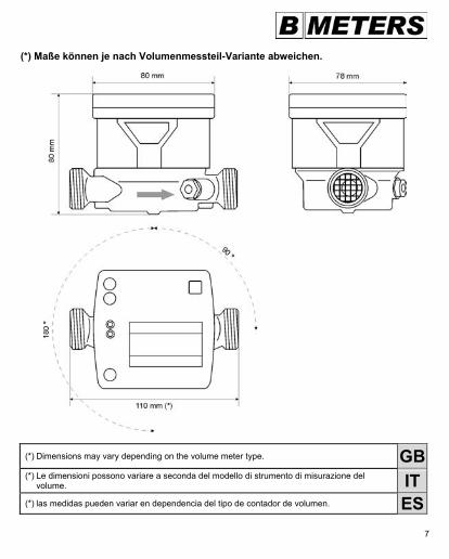
(*) Maße können je nach Volumenmessteil-Variante abweichen.
(*) Dimensions may vary depending on the volume meter type. GB(*) Le dimensioni possono variare a seconda del modello di strumento di misurazione del volume. IT(*) las medidas pueden variar en dependencia del tipo de contador de volumen. ES
8
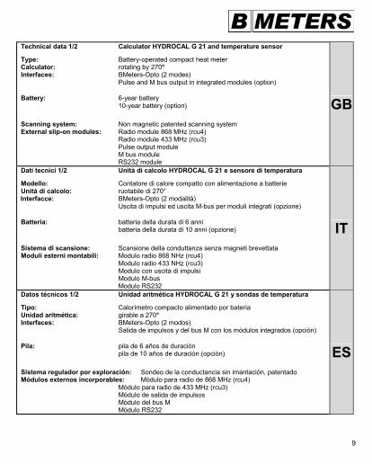
Technische Daten 1/2 Rechenwerk HYDROCAL G 21 und Temperaturfühler Typ: Batteriebetriebener Kompakt-Wärmezähler Rechenwerk: 270 ° drehbar Schnittstellen: BMeters-Opto (2 Modi) Impuls- und M-Bus-Ausgang bei integrierten Modulen (Option) Batterie: 6-Jahresbatterie 10-Jahresbatterie (Option) Abtast-System: Magnetfreie patentierte Leitwertabtastung Aufsetzbare externe Module: Funkmodul 868 MHz (rcu4) Funkmodul 433 MHz (rcu3) Impulsausgangs-Modul M-Bus-Modul RS232-Modul
9
Technical data 1/2 Calculator HYDROCAL G 21 and temperature sensor Type: Battery-operated compact heat meter Calculator: rotating by 270° Interfaces: BMeters-Opto (2 modes) Pulse and M bus output in integrated modules (option) Battery: 6-year battery 10-year battery (option) Scanning system: Non magnetic patented scanning system External slip-on modules: Radio module 868 MHz (rcu4) Radio module 433 MHz (rcu3) Pulse output module M bus module RS232 module
GB
Dati tecnici 1/2 Unità di calcolo HYDROCAL G 21 e sensore di temperatura Modello: Contatore di calore compatto con alimentazione a batterie Unità di calcolo: ruotabile di 270° Interfacce: BMeters-Opto (2 modalità) Uscita di impulsi ed uscita M-bus per moduli integrati (opzione) Batteria: batteria della durata di 6 anni batteria della durata di 10 anni (opzione) Sistema di scansione: Scansione della conduttanza senza magneti brevettata Moduli esterni montabili: Modulo radio 868 NHz (rcu4) Modulo radio 433 NHz (rcu3) Modulo con uscita di impulsi Modulo M-bus Modulo RS232
IT
Datos técnicos 1/2 Unidad aritmética HYDROCAL G 21 y sondas de temperatura Tipo: Calorímetro compacto alimentado por batería Unidad aritmética: girable a 270° Interfaces: BMeters-Opto (2 modos) Salida de impulsos y del bus M con los módulos integrados (opción) Pila: pila de 6 años de duración pila de 10 años de duración (opción) Sistema regulador por exploración: Sondeo de la conductancia sin imantación, patentado Módulos externos incorporables: Módulo para radio de 868 MHz (rcu4) Módulo para radio de 433 MHz (rcu3) Módulo de salida de impulsos Módulo del bus M Módulo RS232
ES
10
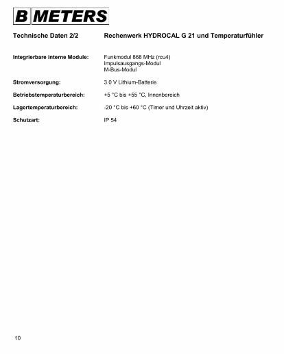
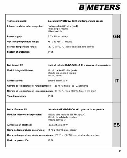
Technische Daten 2/2 Rechenwerk HYDROCAL G 21 und Temperaturfühler Integrierbare interne Module: Funkmodul 868 MHz (rcu4) Impulsausgangs-Modul M-Bus-Modul Stromversorgung: 3.0 V Lithium-Batterie Betriebstemperaturbereich: +5 °C bis +55 °C, Innenbereich Lagertemperaturbereich: -20 °C bis +60 °C (Timer und Uhrzeit aktiv) Schutzart: IP 54
11
Technical data 2/2 Calculator HYDROCAl G 21 and temperature sensor Internal modules to be integrated: Radio module 868 MHz (rcu4) Pulse output module M bus module Power supply: 3.0 V lithium battery Operating temperature range: +5 °C to +55 °C, indoors Storage temperature range: -20 °C to +60 °C (Timer and clock time active) System of protection: IP 54
GB
Dati tecnici 2/2 Unità di calcolo HYDROCAL G 21 e sensore di temperatura Moduli integrabili interni: Modulo radio 868 NHz (rcu4) Modulo con uscita di impulsi Modulo M-bus Alimentazione: batteria al litio 3,0 V Gamma di temperature di funzionamento: da +5 °C fino a +55 °C, all’interno Gamma di temperature di immagazzinaggio: da -20 °C fino a +60 °C (timer e ora attivi) Tipo di protezione: IP 54
IT
Datos técnicos 2/2 Unidad aritmética HYDROCAL G 21 y sondas de temperatura Módulos internos incorporables: Módulo para radio de 868 MHz (rcu4) Módulo de salida de impulsos Módulo del bus M Alimentación eléctrica: Pila de litio de 3.0 V Gama de temperaturas de servicio: +5 °C a +55 °C, en el interior Gama de temperaturas de almacenamiento: -20 °C a +60 °C (temporizador y hora activos) Modo de protección: IP 54
ES
12
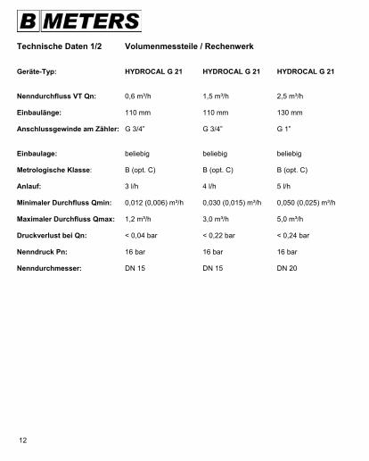
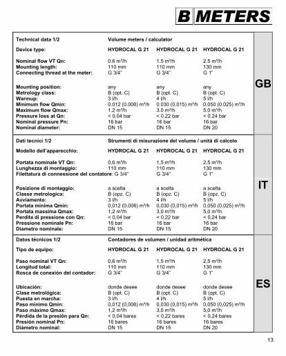
Technische Daten 1/2 Volumenmessteile / Rechenwerk Geräte-Typ: HYDROCAL G 21 HYDROCAL G 21 HYDROCAL G 21 Nenndurchfluss VT Qn: 0,6 m³/h 1,5 m³/h 2,5 m³/h Einbaulänge: 110 mm 110 mm 130 mm Anschlussgewinde am Zähler: G 3/4” G 3/4” G 1” Einbaulage: beliebig beliebig beliebig Metrologische Klasse: B (opt. C) B (opt. C) B (opt. C) Anlauf: 3 l/h 4 l/h 5 l/h Minimaler Durchfluss Qmin: 0,012 (0,006) m³/h 0,030 (0,015) m³/h 0,050 (0,025) m³/h Maximaler Durchfluss Qmax: 1,2 m³/h 3,0 m³/h 5,0 m³/h Druckverlust bei Qn: < 0,04 bar < 0,22 bar < 0,24 bar Nenndruck Pn: 16 bar 16 bar 16 bar Nenndurchmesser: DN 15 DN 15 DN 20
13
Technical data 1/2 Volume meters / calculator Device type: HYDROCAL G 21 HYDROCAL G 21 HYDROCAL G 21 Nominal flow VT Qn: 0.6 m³/h 1.5 m³/h 2.5 m³/h Mounting length: 110 mm 110 mm 130 mm Connecting thread at the meter: G 3/4” G 3/4” G 1” Mounting position: any any any Metrology class: B (opt. C) B (opt. C) B (opt. C) Warmup: 3 l/h 4 l/h 5 l/h Minimum flow Qmin: 0.012 (0.006) m³/h 0.030 (0.015) m³/h 0.050 (0.025) m³/h Maximum flow Qmax: 1.2 m³/h 3.0 m³/h 5.0 m³/h Pressure loss at Qn: < 0.04 bar < 0.22 bar < 0.24 bar Nominal pressure Pn: 16 bar 16 bar 16 bar Nominal diameter: DN 15 DN 15 DN 20
GB
Dati tecnici 1/2 Strumenti di misurazione del volume / unità di calcolo Modello dell’apparecchio: HYDROCAL G 21 HYDROCAL G 21 HYDROCAL G 21 Portata nominale VT Qn: 0,6 m³/h 1,5 m³/h 2,5 m³/h Lunghezza di montaggio: 110 mm 110 mm 130 mm Filettatura di connessione del contatore: G 3/4“ G 3/4“ G 1” Posizione di montaggio: a scelta a scelta a scelta Classe metrologica: B (opz. C) B (opz. C) B (opz. C) Avviamento: 3 l/h 4 l/h 5 l/h Portata minima Qmin: 0,012 (0,006) m³/h 0,030 (0,015) m³/h 0,050 (0,025) m³/h Portata massima Qmax: 1,2 m³/h 3,0 m³/h 5,0 m³/h Perdita di pressione con Qn: < 0,04 bar < 0,22 bar < 0,24 bar Pressione nominale Pn: 16 bar 16 bar 16 bar Diametro nominale: DN 15 DN 15 DN 20
IT
Datos técnicos 1/2 Contadores de volumen / unidad aritmética Tipo de equipo: HYDROCAL G 21 HYDROCAL G 21 HYDROCAL G 21 Paso nominal VT Qn: 0,6 m³/h 1,5 m³/h 2,5 m³/h Longitud total: 110 mm 110 mm 130 mm Rosca de conexión del contador: G 3/4” G 3/4” G 1” Ubicación: donde desee donde desee donde desee Clase metrológica: B (opt. C) B (opt. C) B (opt. C) Puesta en marcha: 3 l/h 4 l/h 5 l/h Paso mínimo Qmin: 0,012 (0,006) m³/h 0,030 (0,015) m³/h 0,050 (0,025) m³/h Paso máximo Qmax: 1,2 m³/h 3,0 m³/h 5,0 m³/h Pérdida de la presión para Qn: < 0,04 bares < 0,22 bares < 0,24 bares Presión nominal Pn: 16 bares 16 bares 16 bares Diámetro nominal: DN 15 DN 15 DN 20
ES
14
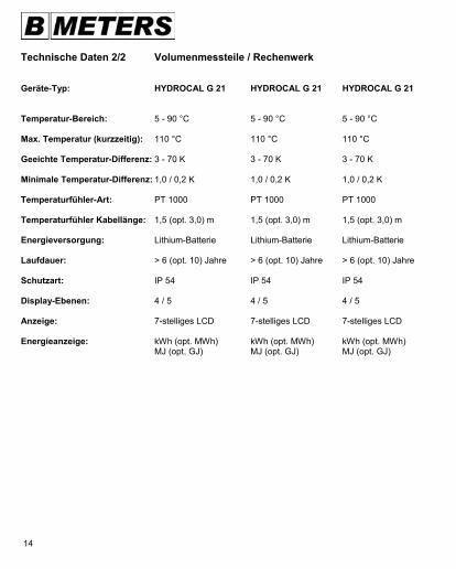
Technische Daten 2/2 Volumenmessteile / Rechenwerk Geräte-Typ: HYDROCAL G 21 HYDROCAL G 21 HYDROCAL G 21 Temperatur-Bereich: 5 - 90 °C 5 - 90 °C 5 - 90 °C Max. Temperatur (kurzzeitig): 110 °C 110 °C 110 °C Geeichte Temperatur-Differenz: 3 - 70 K 3 - 70 K 3 - 70 K Minimale Temperatur-Differenz: 1,0 / 0,2 K 1,0 / 0,2 K 1,0 / 0,2 K Temperaturfühler-Art: PT 1000 PT 1000 PT 1000 Temperaturfühler Kabellänge: 1,5 (opt. 3,0) m 1,5 (opt. 3,0) m 1,5 (opt. 3,0) m Energieversorgung: Lithium-Batterie Lithium-Batterie Lithium-Batterie Laufdauer: > 6 (opt. 10) Jahre > 6 (opt. 10) Jahre > 6 (opt. 10) Jahre Schutzart: IP 54 IP 54 IP 54 Display-Ebenen: 4 / 5 4 / 5 4 / 5 Anzeige: 7-stelliges LCD 7-stelliges LCD 7-stelliges LCD Energieanzeige: kWh (opt. MWh) kWh (opt. MWh) kWh (opt. MWh) MJ (opt. GJ) MJ (opt. GJ) MJ (opt. GJ)
15
Technical data 2/2 Volume meters / calculator Device type: HYDROCAL G 21 HYDROCAL G 21 HYDROCAL G 21 Temperature range: 5 - 90 °C 5 - 90 °C 5 - 90 °C Max. temperature (for a brief period): 110 °C 110 °C 110 °C Calibrated temperature difference: 3 - 70 K 3 - 70 K 3 - 70 K Minimum temperature difference: 1.0 / 0.2 K 1.0 / 0.2 K 1.0 / 0.2 K Type of temperature sensor: PT 1000 PT 1000 PT 1000 Temperature sensor cable length: 1.5 (opt. 3.0) m 1.5 (opt. 3.0) m 1.5 (opt. 3.0) m Power supply: Lithium battery Lithium battery Lithium battery Service life: > 6 (opt. 10) years > 6 (opt. 10) years > 6 (opt. 10) years System of protection: IP 54 IP 54 IP 54 Display levels: 4 / 5 4 / 5 4 / 5 Display: 7-digit LCD 7-digit LCD 7-digit LCD Energy display: kWh (opt. MWh) kWh (opt. MWh) kWh (opt. MWh) MJ (opt. GJ) MJ (opt. GJ) MJ (opt. GJ)
GB
Dati tecnici 2/2 Strumenti di misurazione del volume / unità di calcolo Modello dell’apparecchio: HYDROCAL G 21 HYDROCAL G 21 HYDROCAL G 21 Limiti della temperatura: 5 - 90 °C 5 - 90 °C 5 - 90 °C Temperatura max. (per brevi periodi): 110 °C 110 °C 110 °C Taratura della differenza di temperatura: 3 - 70 K 3 - 70 K 3 - 70 K Differenza di temperatura minima: 1,0 / 0,2 K 1,0 / 0,2 K 1,0 / 0,2 K Tipo di sensore di temperatura: PT 1000 PT 1000 PT 1000 Lunghezza del cavo per il sensore di temperatura: 1,5 (opz. 3,0) m 1,5 (opz. 3,0) m 1,5 (opz. 3,0) m Alimentazione: batteria al litio batteria al litio batteria al litio Durata: > 6 (opz. 10) anni > 6 (opz. 10) anni > 6 (opz. 10) anni Tipo di protezione: IP 54 IP 54 IP 54 Livelli del display: 4 / 5 4 / 5 4 / 5 Display: LCD a 7 caratteri LCD a 7 caratteri LCD a 7 caratteri Indicazione di energia: kWh (opz. MWh) kWh (opz. MWh) kWh (opz. MWh) MJ (opz. GJ) MJ (opz. GJ) MJ (opz. GJ)
IT
Datos técnicos 2/2 Contadores de volumen / unidad aritmética Tipo de equipo: HYDROCAL G 21 HYDROCAL G 21 HYDROCAL G 21 Gama de temperaturas: 5 - 90 °C 5 - 90 °C 5 - 90 °C Temperatura máxima (por poco tiempo): 110 °C 110 °C 110 °C Diferencia de temperatura calibrada: 3 - 70 K 3 - 70 K 3 - 70 K Diferencia mínima de temperatura: 1,0 / 0,2 K 1,0 / 0,2 K 1,0 / 0,2 K Tipo de sonda de temperatura: PT 1000 PT 1000 PT 1000 Longitud del cable de la sonda de temperatura: 1,5 (opt. 3,0) m 1,5 (opt. 3,0) m 1,5 (opt. 3,0) m Suministro de energía: Pila de litio Pila de litio Pila de litio Vida útil: > 6 (opt. 10) años > 6 (opt. 10) años > 6 (opt. 10) años Modo de protección: IP 54 IP 54 IP 54 Niveles de la pantalla: 4 / 5 4 / 5 4 / 5 Visualización: LCD de 7 posiciones LCD de 7 posiciones LCD de 7 posiciones Visualización de la energía: kWh (opt. MWh) kWh (opt. MWh) kWh (opt. MWh) MJ (opt. GJ) MJ (opt. GJ) MJ (opt. GJ)
ES
16
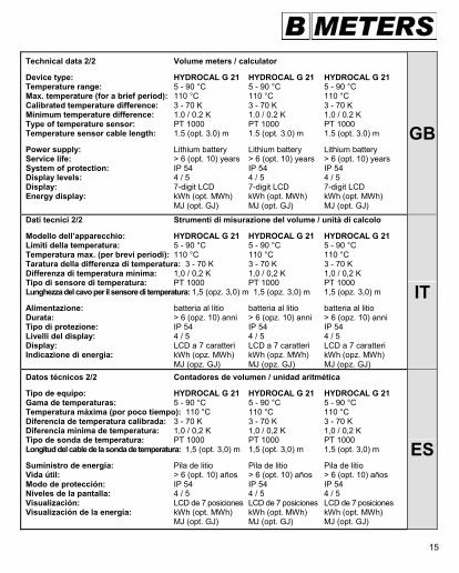
Geräteelemente 1/3
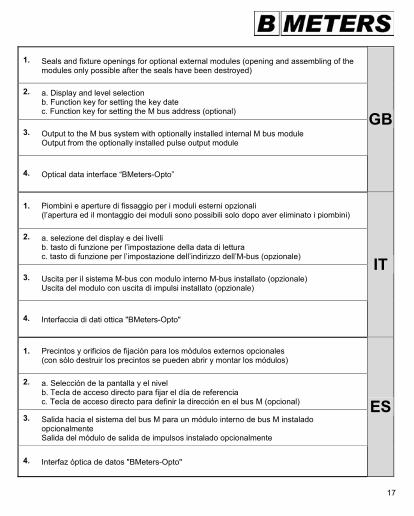
1. Plomben und Befestigungsöffnungen für optionale externe Module (Öffnen und Montage der Module nur durch Zerstörung der Plomben möglich.)
2. a. Display- und Ebenenauswahl b. Funktions-Taste zur Einstellung des Stichtages c. Funktions-Taste zur Einstellung der M-Bus-Adresse (optional)
3. Ausgang zum M-Bus-System beim optional installiertem internen M-Bus-Modul & Ausgang vom optional installiertem Impulsausgangs-Modul
4. Optische Daten-Schnittstelle "BMeters-Opto"
1
3
4
2
17
1. Seals and fixture openings for optional external modules (opening and assembling of the modules only possible after the seals have been destroyed)
2. a. Display and level selection b. Function key for setting the key date c. Function key for setting the M bus address (optional)
3. Output to the M bus system with optionally installed internal M bus module Output from the optionally installed pulse output module
4. Optical data interface “BMeters-Opto”
GB
1. Piombini e aperture di fissaggio per i moduli esterni opzionali (l’apertura ed il montaggio dei moduli sono possibili solo dopo aver eliminato i piombini)
2. a. selezione del display e dei livelli b. tasto di funzione per l’impostazione della data di lettura c. tasto di funzione per l’impostazione dell’indirizzo dell’M-bus (opzionale)
3. Uscita per il sistema M-bus con modulo interno M-bus installato (opzionale) Uscita del modulo con uscita di impulsi installato (opzionale)
4. Interfaccia di dati ottica "BMeters-Opto"
IT
1. Precintos y orificios de fijación para los módulos externos opcionales (con sólo destruir los precintos se pueden abrir y montar los módulos)
2. a. Selección de la pantalla y el nivel b. Tecla de acceso directo para fijar el día de referencia c. Tecla de acceso directo para definir la dirección en el bus M (opcional)
3. Salida hacia el sistema del bus M para un módulo interno de bus M instalado opcionalmente Salida del módulo de salida de impulsos instalado opcionalmente
4. Interfaz óptica de datos "BMeters-Opto"
ES
18
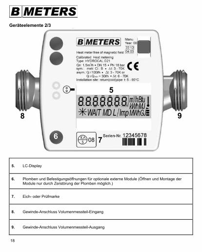
Geräteelemente 2/3
5. LC-Display
6. Plomben und Befestigungsöffnungen für optionale externe Module (Öffnen und Montage der Module nur durch Zerstörung der Plomben möglich.)
7. Eich- oder Prüfmarke
8. Gewinde-Anschluss Volumenmessteil-Eingang
9. Gewinde-Anschluss Volumenmessteil-Ausgang
5
6 7
8 9
19
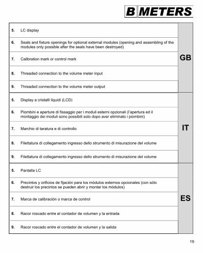
5. LC display
6. Seals and fixture openings for optional external modules (opening and assembling of the modules only possible after the seals have been destroyed)
7. Calibration mark or control mark
8. Threaded connection to the volume meter input
9. Threaded connection to the volume meter output
GB
5. Display a cristalli liquidi (LCD)
6. Piombini e aperture di fissaggio per i moduli esterni opzionali (l’apertura ed il montaggio dei moduli sono possibili solo dopo aver eliminato i piombini)
7. Marchio di taratura e di controllo
8. Filettatura di collegamento ingresso dello strumento di misurazione del volume
9. Filettatura di collegamento ingresso dello strumento di misurazione del volume
IT
5. Pantalla LC
6. Precintos y orificios de fijación para los módulos externos opcionales (con sólo destruir los precintos se pueden abrir y montar los módulos)
7. Marca de calibración o marca de control
8. Racor roscado entre el contador de volumen y la entrada
9. Racor roscado entre el contador de volumen y la salida
ES
20
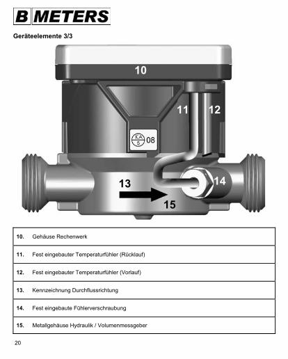
Geräteelemente 3/3
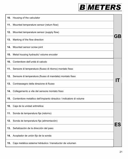
10. Gehäuse Rechenwerk
11. Fest eingebauter Temperaturfühler (Rücklauf)
12. Fest eingebauter Temperaturfühler (Vorlauf)
13. Kennzeichnung Durchflussrichtung
14. Fest eingebaute Fühlerverschraubung
15. Metallgehäuse Hydraulik / Volumenmessgeber
13
10
15
11 12
14
21
10. Housing of the calculator
11. Mounted temperature sensor (return flow)
12. Mounted temperature sensor (supply flow)
13. Marking of the flow direction
14. Mounted sensor screw joint
15. Metal housing hydraulic/ volume encoder
GB
10. Contenitore dell’unità di calcolo
11. Sensore di temperatura (flusso di ritorno) montato fisso
12. Sensore di temperatura (flusso di mandata) montato fisso
13. Contrassegno della direzione di flusso
14. Collegamento a vite del sensore montato fisso
15. Contenitore metallico dell’impianto idraulico / indicatore di volume
IT
10. Caja de la unidad aritmética
11. Sonda de temperatura fija (retorno)
12. Sonda de temperatura fija (alimentación)
13. Señalización de la dirección del paso
14. Acoplador de unión fijo de la sonda
15. Caja metálica sistema hidráulico / transductor de volumen
ES
22
1.
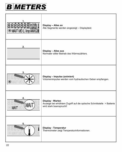
Display – Alles an Alle Segmente werden angezeigt – Displaytest.
2.
Display – Alles aus Normaler stiller Betrieb des Wärmezählers.
3.
Display – Impulse (animiert) Volumenimpulse werden vom hydraulischen Geber empfangen.
4.
Display - Warten Anzeige bei erhöhtem Zugriff auf die optische Schnittstelle > Batterie wird stark beansprucht!
5.
Display - Temperatur Thermometer zeigt Temperaturinformationen.
23
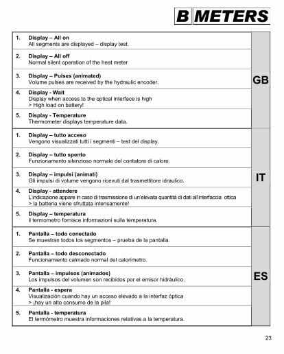
1. Display – All on All segments are displayed – display test.
2. Display – All off Normal silent operation of the heat meter
3. Display – Pulses (animated) Volume pulses are received by the hydraulic encoder.
4. Display - Wait Display when access to the optical interface is high > High load on battery!
5. Display - Temperature Thermometer displays temperature data.
GB
1. Display – tutto acceso Vengono visualizzati tutti i segmenti – test del display.
2. Display – tutto spento Funzionamento silenzioso normale del contatore di calore.
3. Display – impulsi (animati) Gli impulsi di volume vengono ricevuti dal trasmettitore idraulico.
4. Display - attendere L’indicazione appare in caso di trasmissione di un’elevata quantitá di dati all’interfaccia ottica > la batteria viene sfruttata intensamente!
5. Display – temperatura il termometro fornisce informazioni sulla temperatura.
IT
1. Pantalla – todo conectado Se muestran todos los segmentos – prueba de la pantalla.
2. Pantalla – todo desconectado Funcionamiento calmado normal del calorímetro.
3. Pantalla – impulsos (animados) Los impulsos del volumen son recibidos por el emisor hidráulico.
4. Pantalla - espera Visualización cuando hay un acceso elevado a la interfaz óptica > ¡hay un alto consumo de la pila!
5. Pantalla - temperatura El termómetro muestra informaciones relativas a la temperatura.
ES
24
6.
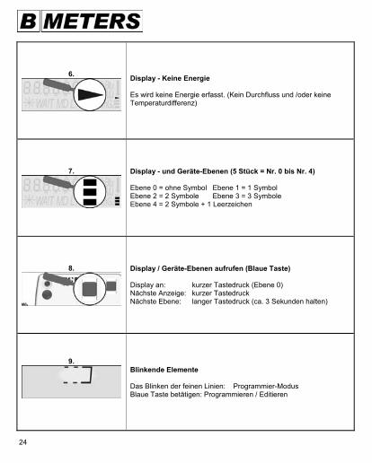
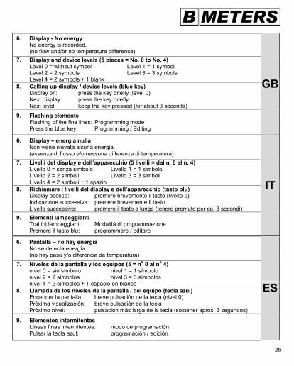
Display - Keine Energie Es wird keine Energie erfasst. (Kein Durchfluss und /oder keine Temperaturdifferenz)
7.
Display - und Geräte-Ebenen (5 Stück = Nr. 0 bis Nr. 4) Ebene 0 = ohne Symbol Ebene 1 = 1 Symbol Ebene 2 = 2 Symbole Ebene 3 = 3 Symbole Ebene 4 = 2 Symbole + 1 Leerzeichen
8.
Display / Geräte-Ebenen aufrufen (Blaue Taste) Display an: kurzer Tastedruck (Ebene 0) Nächste Anzeige: kurzer Tastedruck Nächste Ebene: langer Tastedruck (ca. 3 Sekunden halten)
9.
Blinkende Elemente Das Blinken der feinen Linien: Programmier-Modus Blaue Taste betätigen: Programmieren / Editieren
25
6. Display - No energy No energy is recorded. (no flow and/or no temperature difference) 7. Display and device levels (5 pieces = No. 0 to No. 4) Level 0 = without symbol Level 1 = 1 symbol Level 2 = 2 symbols Level 3 = 3 symbols Level 4 = 2 symbols + 1 blank 8. Calling up display / device levels (blue key) Display on: press the key briefly (level 0) Next display: press the key briefly Next level: keep the key pressed (for about 3 seconds)
9. Flashing elements Flashing of the fine lines: Programming mode Press the blue key: Programming / Editing
GB
6. Display – energia nulla Non viene rilevata alcuna energia. (assenza di flusso e/o nessuna differenza di temperatura) 7. Livelli del display e dell’apparecchio (5 livelli = dal n. 0 al n. 4) Livello 0 = senza simbolo Livello 1 = 1 simbolo Livello 2 = 2 simboli Livello 3 = 3 simboli Livello 4 = 2 simboli + 1 spazio 8. Richiamare i livelli del display e dell’apparecchio (tasto blu) Display acceso: premere brevemente il tasto (livello 0) Indicazione successiva: premere brevemente il tasto Livello successivo: premere il tasto a lungo (tenere premuto per ca. 3 secondi) 9. Elementi lampeggianti Trattini lampeggianti: Modalità di programmazione Premere il tasto blu: programmare / editare
IT
6. Pantalla – no hay energía No se detecta energía. (no hay paso y/o diferencia de temperatura) 7. Niveles de la pantalla y los equipos (5 = no 0 al no 4) nivel 0 = sin símbolo nivel 1 = 1 símbolo nivel 2 = 2 símbolos nivel 3 = 3 símbolos nivel 4 = 2 símbolos + 1 espacio en blanco 8. Llamada de los niveles de la pantalla / del equipo (tecla azul) Encender la pantalla: breve pulsación de la tecla (nivel 0) Próxima visualización: breve pulsación de la tecla Próximo nivel: pulsación más larga de la tecla (sostener aprox. 3 segundos)
9. Elementos intermitentes Líneas finas intermitentes: modo de programación Pulsar la tecla azul: programación / edición
ES
26
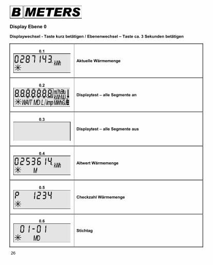
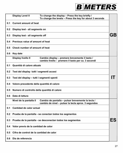
Display Ebene 0 Displaywechsel - Taste kurz betätigen / Ebenenwechsel – Taste ca. 3 Sekunden betätigen
0.1
Aktuelle Wärmemenge
0.2
Displaytest – alle Segmente an
0.3
Displaytest – alle Segmente aus
0.4
Altwert Wärmemenge
0.5
Checkzahl Wärmemenge
0.6
Stichtag
27
Display Level 0 To change the display – Press the key briefly / To change the levels – Press the key for about 3 seconds
0.1 Current amount of heat
0.2 Display test - all segments on
0.3 Display test - all segments off
0.4 Previous value of amount of heat
0.5 Check number of amount of heat
0.6 Key date
GB
Display livello 0 Cambio display – premere brevemente il tasto / cambio livello - premere il tasto per ca. 3 secondi
0.1 Quantitá di calore attuale
0.2 Test del display tutti i segmenti accesi
0.3 Test del display – tutti i segmenti spenti
0.4 Valore precedente della quantità di calore
0.5 Numero di controllo della quantità di calore
0.6 Data di lettura
IT
Nivel de la pantalla 0 Cambio de pantalla – pulsar brevemente la tecla / cambio de nivel – pulsar la tecla aprox. 3 segundos
0.1 Cantidad de calor actual
0.2 Prueba de la pantalla - se conectan todos los segmentos
0.3 Prueba de la pantalla - se desconectan todos los segmentos
0.4 Valor previo de la cantidad de calor
0.5 Cifra de control de la cantidad de calor
0.6 Día de referencia
ES
28
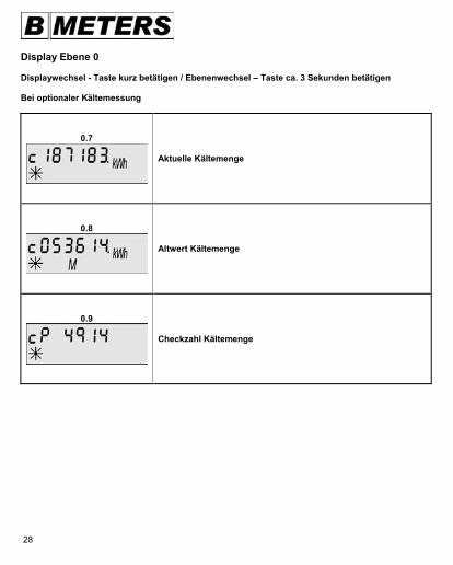
Display Ebene 0 Displaywechsel - Taste kurz betätigen / Ebenenwechsel – Taste ca. 3 Sekunden betätigen Bei optionaler Kältemessung
0.7
Aktuelle Kältemenge
0.8
Altwert Kältemenge
0.9
Checkzahl Kältemenge
29
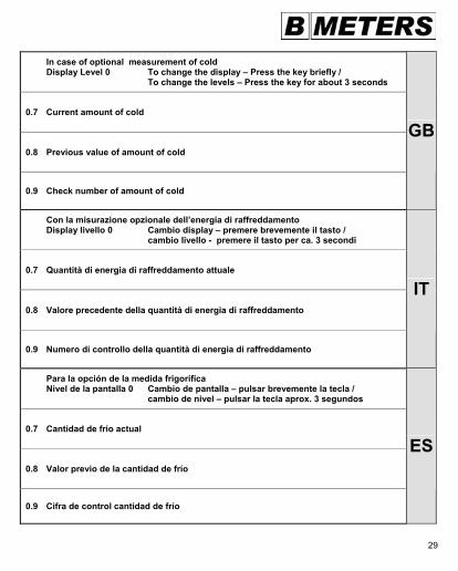
In case of optional measurement of cold Display Level 0 To change the display – Press the key briefly / To change the levels – Press the key for about 3 seconds
0.7 Current amount of cold
0.8 Previous value of amount of cold
0.9 Check number of amount of cold
GB
Con la misurazione opzionale dell’energia di raffreddamento Display livello 0 Cambio display – premere brevemente il tasto / cambio livello - premere il tasto per ca. 3 secondi
0.7 Quantità di energia di raffreddamento attuale
0.8 Valore precedente della quantità di energia di raffreddamento
0.9 Numero di controllo della quantità di energia di raffreddamento
IT
Para la opción de la medida frigorífica Nivel de la pantalla 0 Cambio de pantalla – pulsar brevemente la tecla / cambio de nivel – pulsar la tecla aprox. 3 segundos
0.7 Cantidad de frío actual
0.8 Valor previo de la cantidad de frío
0.9 Cifra de control cantidad de frío
ES
30
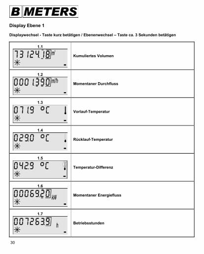
Display Ebene 1 Displaywechsel - Taste kurz betätigen / Ebenenwechsel – Taste ca. 3 Sekunden betätigen
1.1
Kumuliertes Volumen
1.2
Momentaner Durchfluss
1.3
Vorlauf-Temperatur
1.4
Rücklauf-Temperatur
1.5
Temperatur-Differenz
1.6
Momentaner Energiefluss
1.7
Betriebsstunden
31
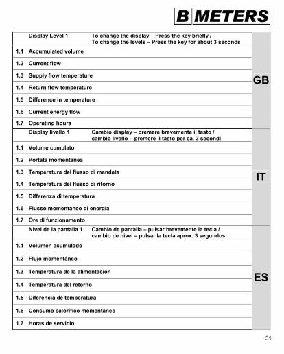
Display Level 1 To change the display – Press the key briefly / To change the levels – Press the key for about 3 seconds 1.1 Accumulated volume
1.2 Current flow
1.3 Supply flow temperature
1.4 Return flow temperature
1.5 Difference in temperature
1.6 Current energy flow
1.7 Operating hours
GB
Display livello 1 Cambio display – premere brevemente il tasto / cambio livello - premere il tasto per ca. 3 secondi 1.1 Volume cumulato
1.2 Portata momentanea
1.3 Temperatura del flusso di mandata
1.4 Temperatura del flusso di ritorno
1.5 Differenza di temperatura
1.6 Flusso momentaneo di energia
1.7 Ore di funzionamento
IT
Nivel de la pantalla 1 Cambio de pantalla – pulsar brevemente la tecla / cambio de nivel – pulsar la tecla aprox. 3 segundos
1.1 Volumen acumulado
1.2 Flujo momentáneo
1.3 Temperatura de la alimentación
1.4 Temperatura del retorno
1.5 Diferencia de temperatura
1.6 Consumo calorífico momentáneo
1.7 Horas de servicio
ES
32
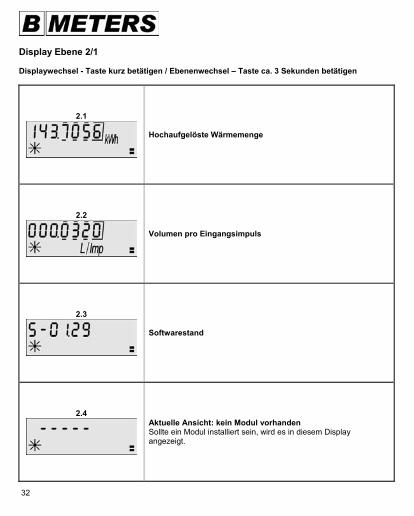
Display Ebene 2/1 Displaywechsel - Taste kurz betätigen / Ebenenwechsel – Taste ca. 3 Sekunden betätigen
2.1
Hochaufgelöste Wärmemenge
2.2
Volumen pro Eingangsimpuls
2.3
Softwarestand
2.4
Aktuelle Ansicht: kein Modul vorhanden Sollte ein Modul installiert sein, wird es in diesem Display angezeigt.
33
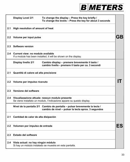
Display Level 2/1 To change the display – Press the key briefly / To change the levels – Press the key for about 3 seconds
2.1 High resolution of amount of heat
2.2 Volume per input pulse
2.3 Software version
2.4 Current view: no module available If a module has been installed, it will be shown on the display.
GB
Display livello 2/1 Cambio display – premere brevemente il tasto / cambio livello - premere il tasto per ca. 3 secondi
2.1 Quantità di calore ad alta precisione
2.2 Volume per impulso ricevuto
2.3 Versione del software
2.4 Visualizzazione attuale: nessun modulo presente Se viene installato un modulo, l’indicazione appare su questo display.
IT
Nivel de la pantalla 2/1 Cambio de pantalla – pulsar brevemente la tecla / cambio de nivel – pulsar la tecla aprox. 3 segundos
2.1 Cantidad de calor de alta disipación
2.2 Volumen por impulso de entrada
2.3 Estado del software
2.4 Vista actual: no hay ningún módulo Si hay un módulo instalado se muestra en esta pantalla.
ES
34
Display Ebene 2/2 Displaywechsel - Taste kurz betätigen / Ebenenwechsel – Taste ca. 3 Sekunden betätigen
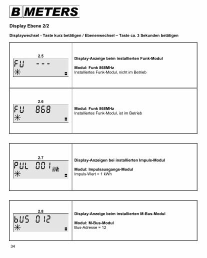
2.5
Display-Anzeige beim installierten Funk-Modul Modul: Funk 868MHz Installiertes Funk-Modul, nicht im Betrieb
2.6
Modul: Funk 868MHz Installiertes Funk-Modul, ist im Betrieb
2.7
Display-Anzeigen bei installierten Impuls-Modul Modul: Impulsausgangs-Modul Impuls-Wert = 1 kWh
2.8
Display-Anzeige beim installierten M-Bus-Modul Modul: M-Bus-Modul Bus-Adresse = 12
35
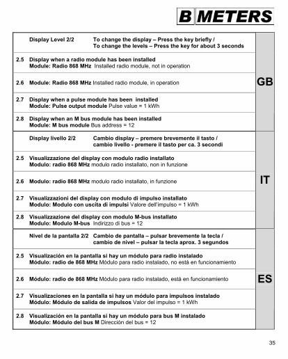
Display Level 2/2 To change the display – Press the key briefly / To change the levels – Press the key for about 3 seconds
2.5 Display when a radio module has been installed Module: Radio 868 MHz Installed radio module, not in operation
2.6 Module: Radio 868 MHz Installed radio module, in operation
2.7 Display when a pulse module has been installed Module: Pulse output module Pulse value = 1 kWh
2.8 Display when an M bus module has been installed Module: M bus module Bus address = 12
GB
Display livello 2/2 Cambio display – premere brevemente il tasto / cambio livello - premere il tasto per ca. 3 secondi
2.5 Visualizzazione del display con modulo radio installato Modulo: radio 868 MHz modulo radio installato, non in funzione
2.6 Modulo: radio 868 MHz modulo radio installato, in funzione
2.7 Visualizzazioni del display con modulo di impulso installato Modulo: Modulo con uscita di impulsi Valore dell’impulso = 1 kWh
2.8 Visualizzazione del display con modulo M-bus installato Modulo: Modulo M-bus Indirizzo di bus = 12
IT
Nivel de la pantalla 2/2 Cambio de pantalla – pulsar brevemente la tecla / cambio de nivel – pulsar la tecla aprox. 3 segundos
2.5 Visualización en la pantalla si hay un módulo para radio instalado Módulo: radio de 868 MHz Módulo para radio instalado, no está en funcionamiento
2.6 Módulo: radio de 868 MHz Módulo para radio instalado, está en funcionamiento
2.7 Visualizaciones en la pantalla si hay un módulo para impulsos instalado Módulo: Módulo de salida de impulsos Valor del impulso = 1 kWh
2.8 Visualización en la pantalla si hay un módulo para bus M instalado Módulo: Módulo del bus M Dirección del bus = 12
ES
36
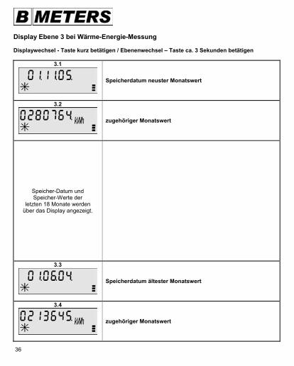
Display Ebene 3 bei Wärme-Energie-Messung Displaywechsel - Taste kurz betätigen / Ebenenwechsel – Taste ca. 3 Sekunden betätigen
3.1
Speicherdatum neuster Monatswert
3.2
zugehöriger Monatswert
Speicher-Datum und Speicher-Werte der
letzten 18 Monate werden über das Display angezeigt.
3.3
Speicherdatum ältester Monatswert
3.4
zugehöriger Monatswert
37
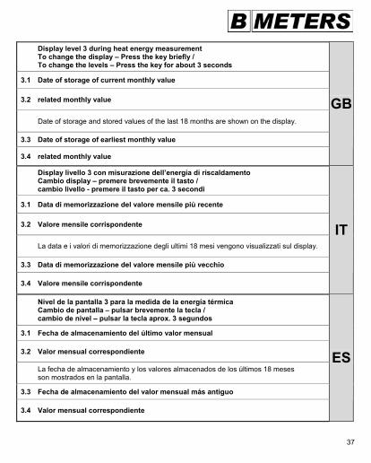
Display level 3 during heat energy measurement To change the display – Press the key briefly / To change the levels – Press the key for about 3 seconds
3.1 Date of storage of current monthly value
3.2 related monthly value
Date of storage and stored values of the last 18 months are shown on the display.
3.3 Date of storage of earliest monthly value
3.4 related monthly value
GB
Display livello 3 con misurazione dell’energia di riscaldamento Cambio display – premere brevemente il tasto / cambio livello - premere il tasto per ca. 3 secondi
3.1 Data di memorizzazione del valore mensile più recente
3.2 Valore mensile corrispondente
La data e i valori di memorizzazione degli ultimi 18 mesi vengono visualizzati sul display.
3.3 Data di memorizzazione del valore mensile più vecchio
3.4 Valore mensile corrispondente
IT
Nivel de la pantalla 3 para la medida de la energía térmica Cambio de pantalla – pulsar brevemente la tecla / cambio de nivel – pulsar la tecla aprox. 3 segundos
3.1 Fecha de almacenamiento del último valor mensual
3.2 Valor mensual correspondiente
La fecha de almacenamiento y los valores almacenados de los últimos 18 meses son mostrados en la pantalla.
3.3 Fecha de almacenamiento del valor mensual más antiguo
3.4 Valor mensual correspondiente
ES
38
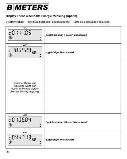
Display Ebene 4 bei Kälte-Energie-Messung (Option) Displaywechsel - Taste kurz betätigen / Ebenenwechsel – Taste ca. 3 Sekunden betätigen
4.1
Speicherdatum neuster Monatswert
4.2
zugehöriger Monatswert
Speicher-Datum und Speicher-Werte der
letzten 18 Monate werden über das Display angezeigt.
4.3
Speicherdatum ältester Monatswert
4.4
zugehöriger Monatswert
39
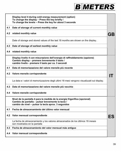
Display level 4 during cold energy measurement (option) To change the display – Press the key briefly / To change the levels – Press the key for about 3 seconds
4.1 Date of storage of current monthly value
4.2 related monthly value
Date of storage and stored values of the last 18 months are shown on the display.
4.3 Date of storage of earliest monthly value
4.4 related monthly value
GB
Display livello 4 con misurazione dell’energia di raffreddamento (opzione) Cambio display – premere brevemente il tasto / cambio livello - premere il tasto per ca. 3 secondi
4.1 Data di memorizzazione del valore mensile più recente
4.2 Valore mensile corrispondente
La data e i valori di memorizzazione degli ultimi 18 mesi vengono visualizzati sul display.
4.3 Data di memorizzazione del valore mensile più vecchio
4.4 Valore mensile corrispondente
IT
Nivel de la pantalla 4 para la medida de la energía frigorífica (opcional) Cambio de pantalla – pulsar brevemente la tecla / cambio de nivel – pulsar la tecla aprox. 3 segundos
4.1 Fecha de almacenamiento del último valor mensual
4.2 Valor mensual correspondiente
La fecha de almacenamiento y los valores almacenados de los últimos 18 meses son mostrados en la pantalla
4.3 Fecha de almacenamiento del valor mensual más antiguo
4.4 Valor mensual correspondiente
ES
40
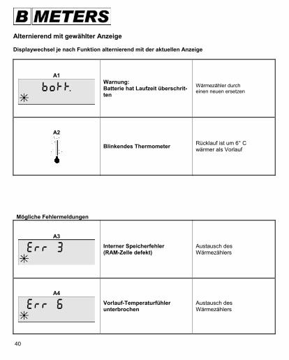
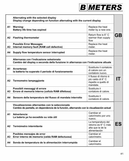
Alternierend mit gewählter Anzeige Displaywechsel je nach Funktion alternierend mit der aktuellen Anzeige
A1
Warnung: Batterie hat Laufzeit überschrit-ten
Wärmezähler durch einen neuen ersetzen
A2
Blinkendes Thermometer Rücklauf ist um 6° C wärmer als Vorlauf
Mögliche Fehlermeldungen
A3
Interner Speicherfehler (RAM-Zelle defekt)
Austausch des Wärmezählers
A4
Vorlauf-Temperaturfühler unterbrochen
Austausch des Wärmezählers
41
Alternating with the selected display Display change depending on function alternating with the current display
A1 Warning: Battery life time has expired
Replace the heat meter by a new one.
A2 Flashing thermometer Return flow is 6° C warmer than supply flow
Possible Error Messages A3 Internal memory fault (RAM cell defective)
Replace the heat meter.
A4 Supply flow temperature sensor interrupted Replace the heat meter.
GB
Alternanza con l’indicazione selezionata Cambio del display a seconda della funzione in alternanza con l’indicazione attuale
A1 Avvertenza: la batteria ha superato il periodo di funzionamento
Sostituire il contatore di calore con un contatore nuovo.
A2 Termometro lampeggiante Il flusso di ritorno è più caldo di 6° C rispetto a quello di mandata.
Possibili messaggi di errore A3 Errore di memoria interno (cellula RAM difettosa)
Sostituire il contatore di calore.
A4 Sensore della temperatura del flusso di mandata interrotto Sostituire il contatore di calore.
IT
Visualizaciones alternantes con la seleccionada Cambio de pantalla, en dependencia de la función, alternando con la visualización actual
A1 Advertencia: La batería ya ha excedido su vida útil
Cambiar el calorímetro por uno nuevo.
A2 Termómetro intermitente La temperatura del retorno es 6° C más alta que la de la alimentación
Posibles mensajes de error A3 Error interno de memoria (celda RAM defectuosa)
Cambiar el calorímetro.
A4 Sonda de temperatura de la alimentación interrumpida Cambiar el calorímetro.
ES
42
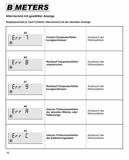
Alternierend mit gewählter Anzeige Displaywechsel je nach Funktion alternierend mit der aktuellen Anzeige
A5
Vorlauf-Temperaturfühler kurzgeschlossen
Austausch des Wärmezählers
A6
Rücklauf-Temperaturfühler unterbrochen
Austausch des Wärmezählers
A7
Rücklauf-Temperaturfühler kurzgeschlossen
Austausch des Wärmezählers
A8
Interner Prüfsummenfehler der aktuellen Wärme- oder Kältemenge
Austausch des Wärmezählers
A9
Interner Prüfsummenfehler der Kalibrierungsdaten
Austausch des Wärmezählers
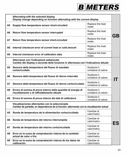
43
Alternating with the selected display Display change depending on function alternating with the current display
A5 Supply flow temperature sensor short-circuited Replace the heat meter.
A6 Return flow temperature sensor interrupted Replace the heat meter.
A7 Return flow temperature sensor short-circuited Replace the heat meter.
A8 Internal checksum error of current heat or cold amount Replace the heat meter.
A9 Internal checksum error of calibration data Replace the heat meter.
GB
Alternanza con l’indicazione selezionata Cambio del display a seconda della funzione in alternanza con l’indicazione attuale
A5 Sensore della temperatura del flusso di mandata cortocircuitato
Sostituire il contatore di calore.
A6 Sensore della temperatura del flusso di ritorno interrotto Sostituire il contatore di calore.
A7 Sensore della temperatura del flusso di ritorno cortocircuitato Sostituire il contatore di calore.
A8 Errore di somma di prova interno della quantità di energia di riscaldamento o di raffreddamento attuale
Sostituire il contatore di calore.
A9 Errore di somma di prova interno dei dati di calibratura Sostituire il contatore di calore.
IT
Visualizaciones alternantes con la seleccionada Cambio de pantalla, en dependencia de la función, alternando con la visualización actual
A5 Sonda de temperatura de la alimentación cortocircuitada Cambiar el calorímetro.
A6 Sonda de temperatura del retorno interrumpida Cambiar el calorímetro.
A7 Sonda de temperatura del retorno cortocircuitada Cambiar el calorímetro.
A8 Error en la suma de comprobación interna de la cantidad actual de calor o frío
Cambiar el calorímetro.
A9 Error en la suma de comprobación interna de los datos de calibración
Cambiar el calorímetro.
ES
44
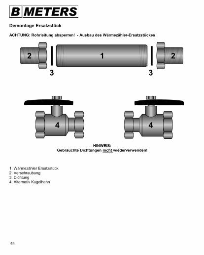
Demontage Ersatzstück ACHTUNG: Rohrleitung absperren! - Ausbau des Wärmezähler-Ersatzstückes
HINWEIS: Gebrauchte Dichtungen nicht wiederverwenden!
1. Wärmezähler Ersatzstück 2. Verschraubung 3. Dichtung 4. Alternativ Kugelhahn
3
4
2 1 2
3
4
45
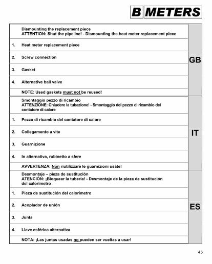
Dismounting the replacement piece ATTENTION: Shut the pipeline! - Dismounting the heat meter replacement piece
1. Heat meter replacement piece
2. Screw connection
3. Gasket
4. Alternative ball valve
NOTE: Used gaskets must not be reused!
GB
Smontaggio pezzo di ricambio ATTENZIONE: Chiudere la tubazione! - Smontaggio del pezzo di ricambio del contatore di calore
1. Pezzo di ricambio del contatore di calore
2. Collegamento a vite
3. Guarnizione
4. In alternativa, rubinetto a sfere
AVVERTENZA: Non riutilizzare le guarnizioni usate!
IT
Desmontaje – pieza de sustitución ATENCIÓN: ¡Bloquear la tubería! - Desmontaje de la pieza de sustitución del calorímetro
1. Pieza de sustitución del calorímetro
2. Acoplador de unión
3. Junta
4. Llave esférica alternativa
NOTA: ¡Las juntas usadas no pueden ser vueltas a usar!
ES
46
Einbau des Wärmezählers (Volumenmessteil) - Nach Einbau Rohrleitung öffnen!
3
1
3
2 2
1. HYDROCAL G 212. Verschraubung 3. Dichtung 4. Alternativ Kugelhahn
4 4
HINWEIS:Durchflussrichtung beachten (Pfeil auf Volumenmessteil)!
Ausschließlich die neuen Original BMeters-
Heißwasserdichtungen verwenden.
OK OK
47
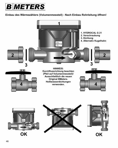
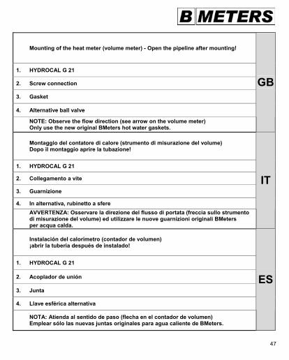
Mounting of the heat meter (volume meter) - Open the pipeline after mounting!
1. HYDROCAL G 21
2. Screw connection
3. Gasket
4. Alternative ball valve
NOTE: Observe the flow direction (see arrow on the volume meter) Only use the new original BMeters hot water gaskets.
GB
Montaggio del contatore di calore (strumento di misurazione del volume) Dopo il montaggio aprire la tubazione!
1. HYDROCAL G 21
2. Collegamento a vite
3. Guarnizione
4. In alternativa, rubinetto a sfere AVVERTENZA: Osservare la direzione del flusso di portata (freccia sullo strumento di misurazione del volume) ed utilizzare le nuove guarnizioni originali BMeters per acqua calda.
IT
Instalación del calorímetro (contador de volumen) ¡abrir la tubería después de instalado!
1. HYDROCAL G 21
2. Acoplador de unión
3. Junta
4. Llave esférica alternativa
NOTA: Atienda al sentido de paso (flecha en el contador de volumen) Emplear sólo las nuevas juntas originales para agua caliente de BMeters.
ES
48
Montage direkte Messung Kugelhahn M10x1 / 1/4" ACHTUNG: Rohrleitung absperren! - Einbau des Vorlauf-Temperaturfühlers
1/4" M10x1
1. O-Ring 2. Kunststoffscheibe 3. Schraubhülse 1
Die Schraubhülse inklusive der Kunststoff- und Dichtteile sind teilweise bereits am Fühler werkseitig vormontiert.
M10x1
2
3
1/4"
Variantenbeispiel
49
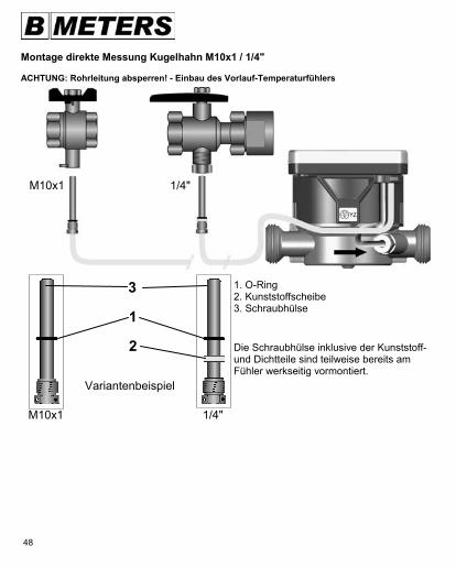
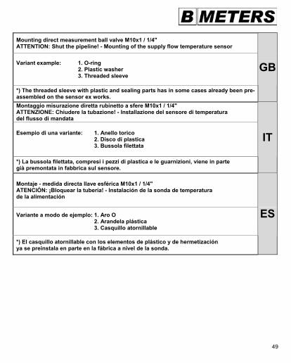
Mounting direct measurement ball valve M10x1 / 1/4" ATTENTION: Shut the pipeline! - Mounting of the supply flow temperature sensor
Variant example: 1. O-ring 2. Plastic washer 3. Threaded sleeve
*) The threaded sleeve with plastic and sealing parts has in some cases already been pre-assembled on the sensor ex works.
GB
Montaggio misurazione diretta rubinetto a sfere M10x1 / 1/4" ATTENZIONE: Chiudere la tubazione! - Installazione del sensore di temperatura del flusso di mandata
Esempio di una variante: 1. Anello torico 2. Disco di plastica 3. Bussola filettata
*) La bussola filettata, compresi i pezzi di plastica e le guarnizioni, viene in parte già premontata in fabbrica sul sensore.
IT
Montaje - medida directa llave esférica M10x1 / 1/4" ATENCIÓN: ¡Bloquear la tubería! - Instalación de la sonda de temperatura de la alimentación
Variante a modo de ejemplo: 1. Aro O 2. Arandela plástica 3. Casquillo atornillable
*) El casquillo atornillable con los elementos de plástico y de hermetización ya se preinstala en parte en la fábrica a nivel de la sonda.
ES
50
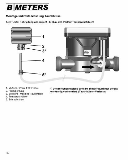
Montage indirekte Messung Tauchhülse ACHTUNG: Rohrleitung absperren! - Einbau des Vorlauf-Temperaturfühlers
1. Muffe für Vorlauf TF-Einbau 2. Flachdichtung 3. BMeters - Messing-Tauchhülse 4. Temperaturfühler 5. Schraubhülse
1 2 3* 4 5*
*) Die Befestigungsteile sind am Temperaturfühler bereits werkseitig vormontiert. (Tauchhülsen-Variante)
51
Mounting indirect measurement immersion sleeve ATTENTION: Shut the pipeline! - Mounting of the supply flow temperature sensor
1. Pipe sleeve for supply flow Installation of TS
2. Flat gasket
3. BMeters – brass immersion sleeve
4. Temperature sensor
5. Threaded sleeve
*) The fastening components on the temperature sensor have already been pre- mounted ex works immersion sleeve variant
GB
Montaggio misurazione indiretta (bussola ad immersione) ATTENZIONE: Chiudere la tubazione! - Installazione del sensore di temperatura del flusso di mandata 1. Manicotto per il flusso di mandata Installazione del sensore di temperatura
2. Guarnizione piatta
3. Bussola ad immersione BMeters in ottone
4. Sensore di temperatura
5. Bussola filettata *) I pezzi di fissaggio sono già stati premontati in fabbrica sulla sonda termica variante con bussola ad immersione
IT
Montaje – medida indirecta (casquillo de inmersión) ATENCIÓN: ¡Bloquear la tubería! - Instalación de la sonda de temperatura de la alimentación
1. Manguito del tubo de alimentación Montaje de la sonda
2. Junta plana
3. Casquillo de inmersión de latón de BMeters
4. Sonda de temperatura
5. Casquillo atornillable *) Las piezas de sujeción ya se preinstalan en la sonda de temperatura en la fábrica. (variante con casquillo de inmersión)
ES
52
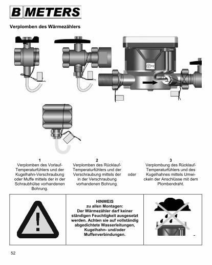
Verplomben des Wärmezählers
1 Verplomben des Vorlauf-
Temperaturfühlers und der Kugelhahn-Verschraubung
oder Muffe mittels der in der Schraubhülse vorhandenen
Bohrung.
2 Verplomben des Rücklauf-Temperaturfühlers und der Verschraubung mittels der
in der Verschraubung vorhandenen Bohrung.
oder
3 Verplombung des Rücklauf-Temperaturfühlers und des Kugelhahnes mittels Umwi-
ckeln der Anschlüsse mit dem Plombendraht.
HINWEIS
zu allen Montagen: Der Wärmezähler darf keiner
ständigen Feuchtigkeit ausgesetzt werden. Achten sie auf vollständig
abgedichtete Wasserleitungen, Kugelhahn- und/oder Muffenverbindungen.
53
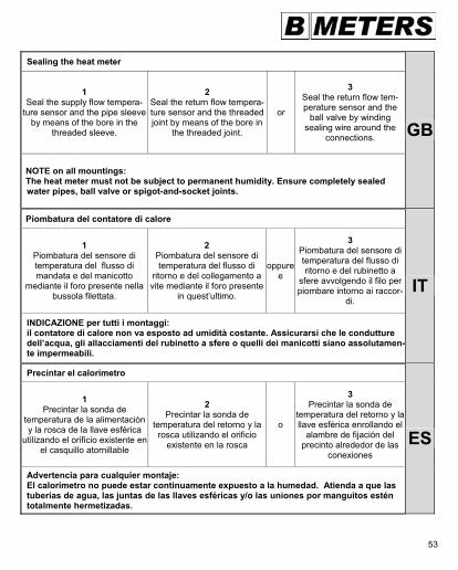
Sealing the heat meter
1 Seal the supply flow tempera-
ture sensor and the pipe sleeve by means of the bore in the
threaded sleeve.
2 Seal the return flow tempera-ture sensor and the threaded joint by means of the bore in
the threaded joint.
or
3 Seal the return flow tem-perature sensor and the
ball valve by winding sealing wire around the
connections.
NOTE on all mountings: The heat meter must not be subject to permanent humidity. Ensure completely sealed water pipes, ball valve or spigot-and-socket joints.
GB
Piombatura del contatore di calore
1 Piombatura del sensore di temperatura del flusso di mandata e del manicotto
mediante il foro presente nella bussola filettata.
2 Piombatura del sensore di temperatura del flusso di
ritorno e del collegamento a vite mediante il foro presente
in quest’ultimo.
oppure e
3 Piombatura del sensore di temperatura del flusso di ritorno e del rubinetto a
sfere avvolgendo il filo per piombare intorno ai raccor-
di.
INDICAZIONE per tutti i montaggi: il contatore di calore non va esposto ad umidità costante. Assicurarsi che le condutture dell’acqua, gli allacciamenti del rubinetto a sfere o quelli dei manicotti siano assolutamen-te impermeabili.
IT
Precintar el calorímetro
1 Precintar la sonda de
temperatura de la alimentación y la rosca de la llave esférica
utilizando el orificio existente en el casquillo atornillable
2 Precintar la sonda de
temperatura del retorno y la rosca utilizando el orificio
existente en la rosca
o
3 Precintar la sonda de
temperatura del retorno y la llave esférica enrollando el
alambre de fijación del precinto alrededor de las
conexiones
Advertencia para cualquier montaje: El calorímetro no puede estar continuamente expuesto a la humedad. Atienda a que lastuberías de agua, las juntas de las llaves esféricas y/o las uniones por manguitos estén totalmente hermetizadas.
ES
54
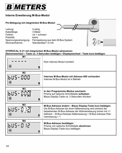
Interne Erweiterung M-Bus-Modul Pin-Belegung mit integriertem M-Bus-Modul: Leitung: 2-adrig Kabellänge: 3 Meter Farben: rot + schwarz Polarität: keine Spannungsversorgung: Fernspeisung aus dem M-Bus-System Stromaufnahme: Standardlast 1,5 mA HYDROCAL G 21 mit integriertem M-Bus-Modul adressieren Ebenenwechsel – Taste ca. 3 Sekunden betätigen / Displaywechsel - Taste kurz betätigen
M1
Kein internes Modul montiert
M2
Internes M-Bus-Modul mit Adresse 000 vorhanden Internes M-Bus-Modul ist in Betrieb
M3
In den Programmier-Modus wechseln Prisma auf optische Schnittstelle aufsetzen Blaue Display-Taste ca. 3 Sekunden drücken
M3
M-Bus-Adresse ändern - Blaue Display-Taste kurz betätigen Die M-Bus-Adresse bei einer Kältemessung wird anhand der bestehenden M-Bus-Adresse der Wärmemessung immer mit +1 definiert. - M-Bus-Adresse Kältemessung = M-Bus-Adresse Wär-memessung + 1
M4
M-Bus-Adresse bestätigen Prisma von optische Schnittstelle abnehmen Blaue Display-Taste kurz betätigen
55
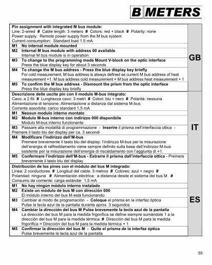
Pin assignment with integrated M bus module: Line: 2-wired # Cable length: 3 meters # Colors: red + black # Polarity: none Power supply: Remote power supply from the M bus system Current consumption: Standard load 1.5 mA M1 No internal module mounted M2 Internal M bus module with address 00 available Internal M bus module is in operation M3 To change to the programming mode Mount V-block on the optic interface Press the blue display key for about 3 seconds M4 To change the M bus address - Press the blue display key briefly For cold measurement, M bus address is always defined as current M bus address of heat measurement +1. M bus address cold measurement = M bus address heat measurement + 1 M5 To confirm the M bus address - Dismount the prism from the optic interface Press the blue display key briefly
GB
Descrizione delle uscite pin con il modulo M-bus integrato: Cavo: a 2 fili # Lunghezza cavo: 3 metri # Colori: blu + nero # Polaritá: nessuna Alimentazione di tensione: Alimentazione a distanza dal sistema M-bus Corrente assorbita: carico standard 1,5 mA M1 Nessun modulo interno montato M2 Modulo M-bus interno con indirizzo 000 disponibile Modulo M-bus interno funzionante M3 Passare alla modalità di programmazione - Inserire il prisma nell’interfaccia ottica - Premere il tasto blu del display per ca. 3 secondi M4 Modificare l’indirizzo dell’M-bus Premere brevemente il tasto blu del display. l’indirizzo M-bus per la misurazione dell’energia di raffreddamento viene sempre definito sulla base dell’indirizzo M-bus esistente per la misurazione dell’energia di riscaldamento con l’aggiunta di +1. M5 Confermare l’indirizzo dell’M-bus - Estrarre il prisma dall’interfaccia ottica - Premere brevemente il tasto blu del display
IT
Distribución de los pines con el módulo del bus M integrado: Línea: 2 conductores # Longitud del cable: 3 metros # Colores: azul + negro # Polaridad: ninguna # Alimentación eléctrica: a distancia desde el sistema del bus M # Consumo de corriente: carga estándar 1,5 mA M1 No hay ningún módulo interno instalado M2 Existe un módulo de bus M con dirección 000 El módulo interno del bus M está funcionando M3 Cambiar al modo de programación - Coloque el prisma en la interfaz óptica Pulse la tecla azul de la pantalla durante aprox. 3 segundos M4 Cambiar la dirección del bus M Pulse brevemente la tecla azul de la pantalla La dirección del bus M para la medida frigorífica se define siempre sumándole 1 a la dirección del bus M para la medida térmica. # Dirección del bus M para la medida frigorífica = Dirección del bus M para la medida térmica + 1 M5 Confirmar la dirección del bus M - Quite el prisma de la interfaz óptica Pulse brevemente la tecla azul de la pantalla
ES
56
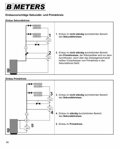
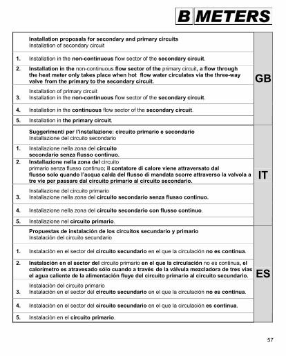
Einbauvorschläge Sekundär- und Primärkreis Einbau Sekundärkreis
1. Einbau im nicht ständig durchströmten Bereich des Sekundärkreises. 2. Einbau im nicht ständig durchströmten Bereich des Primärkreises, der Wärmezähler wird nur dann durchflossen, wenn über das Dreiwegemischventil heißes Vorlaufwasser vom Primärkreis in den Sekundärkreis fließt.
Einbau Primärkreis
3. Einbau im nicht ständig durchströmten Bereich des Sekundärkreises. 4. Einbau im ständig durchströmten Bereich des Sekundärkreises. 5. Einbau im Primärkreis.
3
4
5
2
1
57
Installation proposals for secondary and primary circuits Installation of secondary circuit
1. Installation in the non-continuous flow sector of the secondary circuit.
2. Installation in the non-continuous flow sector of the primary circuit, a flow through the heat meter only takes place when hot flow water circulates via the three-way valve from the primary to the secondary circuit.
Installation of primary circuit 3. Installation in the non-continuous flow sector of the secondary circuit.
4. Installation in the continuous flow sector of the secondary circuit.
5. Installation in the primary circuit.
GB
Suggerimenti per l’installazione: circuito primario e secondario Installazione del circuito secondario
1. Installazione nella zona del circuito secondario senza flusso continuo. 2. Installazione nella zona del circuito primario senza flusso continuo; il contatore di calore viene attraversato dal flusso solo quando l’acqua calda del flusso di mandata scorre attraverso la valvola a tre vie per passare dal circuito primario al circuito secondario.
Installazione del circuito primario 3. Installazione nella zona del circuito secondario senza flusso continuo.
4. Installazione nella zona del circuito secondario con flusso continuo.
5. Installazione nel circuito primario.
IT
Propuestas de instalación de los circuitos secundario y primario Instalación del circuito secundario
1. Instalación en el sector del circuito secundario en el que la circulación no es continua.
2. Instalación en el sector del circuito primario en el que la circulación no es continua, el calorímetro es atravesado sólo cuando a través de la válvula mezcladora de tres vías el agua caliente de la alimentación fluye del circuito primario al circuito secundario.
Instalación del circuito primario 3. Instalación en el sector del circuito secundario en el que la circulación no es continua.
4. Instalación en el sector del circuito secundario en el que la circulación es continua.
5. Instalación en el circuito primario.
ES
58
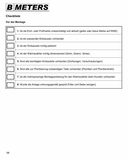
Checkliste Vor der Montage
1. Ist die Eich- oder Prüfmarke unbeschädigt und aktuell (gelbe oder blaue Marke auf WMZ)
2. Ist ein passender Einbausatz vorhanden
3. Ist der Einbausatz richtig platziert
4. Ist der Wärmezähler richtig dimensioniert (Qmin, Qnenn, Qmax)
5. Sind alle benötigten Einbauteile vorhanden (Dichtungen, Verschraubungen)
6. Sind alle zur Plombierung notwendigen Teile vorhanden (Plomben und Plombendraht)
7. Ist die mehrsprachige Montageanleitung für den Wärmezähler beim Kunden vorhanden
8. Wurde die Anlage ordnungsgemäß gespült (Filter und Siebe reinigen)
59
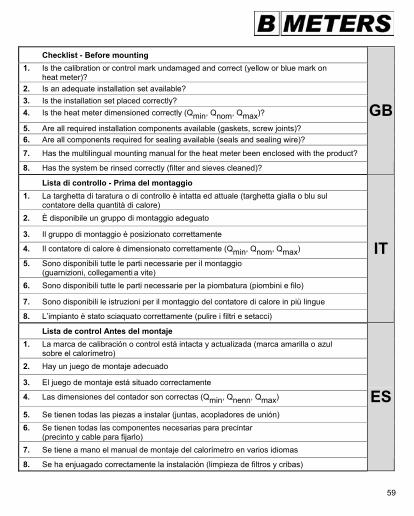
Checklist - Before mounting 1. Is the calibration or control mark undamaged and correct (yellow or blue mark on heat meter)? 2. Is an adequate installation set available? 3. Is the installation set placed correctly? 4. Is the heat meter dimensioned correctly (Qmin, Qnom, Qmax)?
5. Are all required installation components available (gaskets, screw joints)? 6. Are all components required for sealing available (seals and sealing wire)?
7. Has the multilingual mounting manual for the heat meter been enclosed with the product?
8. Has the system be rinsed correctly (filter and sieves cleaned)?
GB
Lista di controllo - Prima del montaggio 1. La targhetta di taratura o di controllo è intatta ed attuale (targhetta gialla o blu sul contatore della quantità di calore) 2. È disponibile un gruppo di montaggio adeguato
3. Il gruppo di montaggio è posizionato correttamente
4. Il contatore di calore è dimensionato correttamente (Qmin, Qnom, Qmax)
5. Sono disponibili tutte le parti necessarie per il montaggio (guarnizioni, collegamenti a vite) 6. Sono disponibili tutte le parti necessarie per la piombatura (piombini e filo)
7. Sono disponibili le istruzioni per il montaggio del contatore di calore in più lingue
8. L’impianto è stato sciaquato correttamente (pulire i filtri e setacci)
IT
Lista de control Antes del montaje 1. La marca de calibración o control está intacta y actualizada (marca amarilla o azul sobre el calorímetro) 2. Hay un juego de montaje adecuado
3. El juego de montaje está situado correctamente
4. Las dimensiones del contador son correctas (Qmin, Qnenn, Qmax)
5. Se tienen todas las piezas a instalar (juntas, acopladores de unión) 6. Se tienen todas las componentes necesarias para precintar (precinto y cable para fijarlo) 7. Se tiene a mano el manual de montaje del calorímetro en varios idiomas
8. Se ha enjuagado correctamente la instalación (limpieza de filtros y cribas)
ES
60
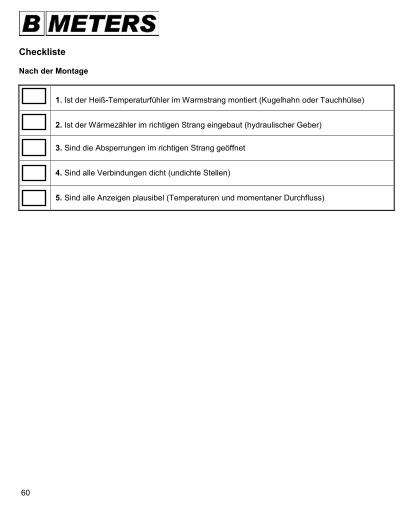
Checkliste Nach der Montage
1. Ist der Heiß-Temperaturfühler im Warmstrang montiert (Kugelhahn oder Tauchhülse)
2. Ist der Wärmezähler im richtigen Strang eingebaut (hydraulischer Geber)
3. Sind die Absperrungen im richtigen Strang geöffnet
4. Sind alle Verbindungen dicht (undichte Stellen)
5. Sind alle Anzeigen plausibel (Temperaturen und momentaner Durchfluss)
61
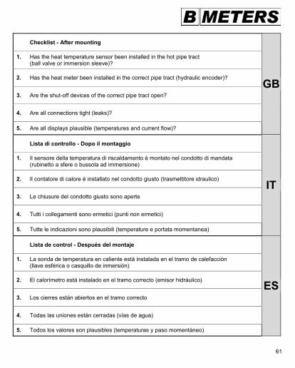
Checklist - After mounting
1. Has the heat temperature sensor been installed in the hot pipe tract (ball valve or immersion sleeve)?
2. Has the heat meter been installed in the correct pipe tract (hydraulic encoder)?
3. Are the shut-off devices of the correct pipe tract open?
4. Are all connections tight (leaks)?
5. Are all displays plausible (temperatures and current flow)?
GB
Lista di controllo - Dopo il montaggio
1. Il sensore della temperatura di riscaldamento è montato nel condotto di mandata (rubinetto a sfere o bussola ad immersione)
2. Il contatore di calore è installato nel condotto giusto (trasmettitore idraulico)
3. Le chiusure del condotto giusto sono aperte
4. Tutti i collegamenti sono ermetici (punti non ermetici)
5. Tutte le indicazioni sono plausibili (temperature e portata momentanea)
IT
Lista de control - Después del montaje
1. La sonda de temperatura en caliente está instalada en el tramo de calefacción (llave esférica o casquillo de inmersión)
2. El calorímetro está instalado en el tramo correcto (emisor hidráulico)
3. Los cierres están abiertos en el tramo correcto
4. Todas las uniones están cerradas (vías de agua)
5. Todos los valores son plausibles (temperaturas y paso momentáneo)
ES
62
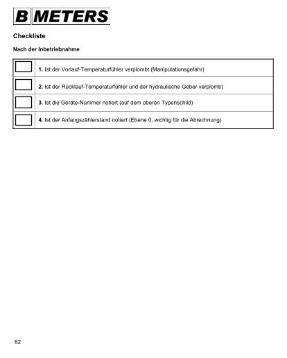
Checkliste Nach der Inbetriebnahme
1. Ist der Vorlauf-Temperaturfühler verplombt (Manipulationsgefahr)
2. Ist der Rücklauf-Temperaturfühler und der hydraulische Geber verplombt
3. Ist die Geräte-Nummer notiert (auf dem oberen Typenschild)
4. Ist der Anfangszählerstand notiert (Ebene 0, wichtig für die Abrechnung)
63
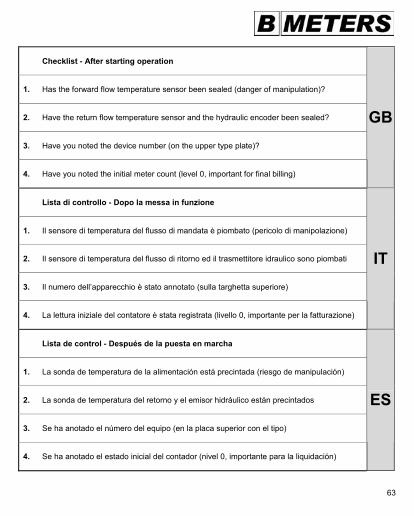
Checklist - After starting operation
1. Has the forward flow temperature sensor been sealed (danger of manipulation)?
2. Have the return flow temperature sensor and the hydraulic encoder been sealed?
3. Have you noted the device number (on the upper type plate)?
4. Have you noted the initial meter count (level 0, important for final billing)
GB
Lista di controllo - Dopo la messa in funzione
1. Il sensore di temperatura del flusso di mandata è piombato (pericolo di manipolazione)
2. Il sensore di temperatura del flusso di ritorno ed il trasmettitore idraulico sono piombati
3. Il numero dell’apparecchio è stato annotato (sulla targhetta superiore)
4. La lettura iniziale del contatore è stata registrata (livello 0, importante per la fatturazione)
IT
Lista de control - Después de la puesta en marcha
1. La sonda de temperatura de la alimentación está precintada (riesgo de manipulación)
2. La sonda de temperatura del retorno y el emisor hidráulico están precintados
3. Se ha anotado el número del equipo (en la placa superior con el tipo)
4. Se ha anotado el estado inicial del contador (nivel 0, importante para la liquidación)
ES

64
Notizen - Notes - Note - Notas


![Die Kennzeichnung des Pkw-Reifens - Cloudinary · 2019-11-21 · (GSY, Speed-Index) zul. Höchst- geschwindigkeit . in [km/h] F 80 S 180 G 90 T 190 J 100 U 200 K 110 H 210 L 120 V](https://static.unterlagen.site/doc/80x56/5f346516a69a667e7c66ae02/die-kennzeichnung-des-pkw-reifens-cloudinary-2019-11-21-gsy-speed-index-zul.jpg)


![Db] M]a Aebanbihm GH...Sahh] l]b[an pih ]e]dnlbm[a]h Kadn]h üZ]l G]aäom]\][d] a zo B]m[aä`]h ül Mö]. noh ohn]lzi`]h oh ]bh S]la]bnmZ]lb[a ]l, \]l \]l B]l-Bnlb]Zeb Aa`]h G]aal]hmbnoanbih]h](https://static.unterlagen.site/doc/80x56/60e02837da82f14008089f0c/db-ma-aebanbihm-gh-sahh-lban-pih-ednlbmah-kadnh-zl-gaomd.jpg)


![Übung zur Intonation Jonathan Harrington [Melanie?]L-H%[Melanie nominieren?]L-H% Tonakzent (H*, L*) : Mit der primär-betonten Silbe des akzentuierten.](https://static.unterlagen.site/doc/80x56/55204d6449795902118ba8f6/uebung-zur-intonation-jonathan-harrington-melaniel-hmelanie-nominierenl-h-tonakzent-h-l-mit-der-primaer-betonten-silbe-des-akzentuierten.jpg)