Forschungszentrum Karlsruhe Technik und Umwelt Wissenschaftliche Berichte FZKA 6192 Electric Fields and ExB Drifts in Hot Plasma Cold Plasma lnteractions I. S. Landman, H. Würz Institut für Neutronenphysik und Reaktortechnik Projekt Kernfusion November 1998
Transcript
Forschungszentrum Karlsruhe Technik und Umwelt
Wissenschaftliche Berichte FZKA 6192
Electric Fields and ExB Drifts in Hot Plasma Cold Plasma lnteractions
I. S. Landman, H. Würz Institut für Neutronenphysik und Reaktortechnik Projekt Kernfusion
November 1998
Forschungszentrum Karlsruhe
Technik und Umwelt
Wissenschaftliche Berichte
FZKA 6192
Electric fields and ExB drifts in hot plasma cold plasma interactions
I.S. Landman*, H. Würz
Institut für Neutronenphysik und Reaktortechnik
Projekt Kernfusion
* permanent address: Troitsk Institute for Innovation and Fusion Research
142092 Troitsk, Russia
This work was performed in the frame of ITER; task T226.b and was supported by German WTZ cooperation agreement under RUS-524-96
Forschungszentrum Karlsruhe GmbH, Karlsruhe 1998
Als Manuskript gedruckt Für diesen Bericht behalten wir uns alle Rechte vor
Mitglied der Hermann von Helmholtz-Gemeinschaft Deutscher Forschungszentren (HGF)
ISSN 0947-8620
Abstract
ln disruptive hot plasma wall interaction a dense and rather cold plasma shield is formed from evaporated material in front of the target at an early stage of the interaction. Electric potential distributions in the plasma shield hot plasma interaction region and energy deposition proflies were calculated both for perpendicular and for the first time also for inclined impact of the hot magnetized plasma along the guiding magnetic field.
For perpendicular impact, the calculation of the electric potential in the plasma shield is based on the Poisson equation and the condition of zero electric current. The analysis for inclined impact of magnetized hot plasma uses a non-stationary Vlasov Maxwell model, the condition of zero current perpendicular to the target and the existence of an uncompensated current in toroidal direction. ln the hot plasma region a significant potential drop occurs resulting in a lateral dritt motion (deflection) of the impacting hot plasma. The evolution of an additional magnetic field could result in a self compression of the plasma shield. The dynamics of this self compression and its consequences for the plasma shield stability and for erosion still need more detailed investigations.
Zusammenfassung
Elektrische Felder und ExB Drift bei der Wechselwirkung eines heißen Plasmas mit einem kalten Plasma
Bei der Wechselwirkung eines heißen disruptiven Plasmas mit einem Target bildet verdampfendes Targetmaterial einen dichten, ziemlich kalten Plasmaschild. Elektrische Potentialverteilungen in der Wechselwirkungszone des Plasmaschildes mit dem heißen Plasma und Energiedepositionsverteilungen im Plasmaschild werden für senkrechten und zum ersten Mal auch für geneigten Einfall des heißen magnetisierten Plasmas berechnet.
Für senkrechten Einfall wird die Potentialverteilung im Plasmaschild mittels Poisson Gleichung und der Bedingung eines kompensierten Stromes berechnet. Für die Analyse bei geneigtem Einfall des magnetisierten heißen Plasmas wird ein nicht stationäres Vlasov Maxwell Modell verwendet. Weitere Annahmen sind ein kompensierter Strom senkrecht zum Target und ein Nettostrom in toroidaler Richtung. Im heißen Plasma tritt ein signifikanter Potentialunterschied auf. Dieser verursacht eine laterale Driftbewegung (Ablenkung) des einfallenden heißen Plasmas. Die Evolution eines zusätzlichen Magnetfeldes könnte eine Kompression des Plasmaschildes bewirken. Die Kompressionsdynamik und seine Konsequenz für die Stabilität des Plasmaschildes und damit für die Targeterosion sind noch detaillierter zu untersuchen.
Content
1 INTRODUCTION 1
2 THE PROBLEM 2
2.1 Definition of sheath and pre-sheather 3
2.2 Inclined impact of bot plasma 5
3 MATHEMATICAL DESCRIPTION FOR PERPENDICULAR IMPACT 7
4 SOLUTION FOR PERPENDICULAR IMPACT 12
4.1 The collisionless infinity 12
4.2 Physical parameters and solution of equations 13
4.3 Energy deposition into the plasma shield 16
4.4 The Bohm criteria 17
5 INCLINED IMPACT OF HOT PLASMA 18
5.1 Collisionless region with inclined impact 18
5.2 Collisional region 22
6 THE MAGNETIC PRE-SHEATH AND THE ELECTROSTATIC SHEATH 29
7 CONCLUSIONS 33
8 ACKNOWLEDGEMENT 34
9 REFERENCES 34
1. INTRODUCTION
Results from numerical modeling of disruptive plasma divertor target interactions1
•2 for the International Thermonuclear Experimental Reactor (ITER)3 and
from disruption simulation experiments4 have clearly shown that evaporated divertor material forms a dense rather cold plasma shield which protects the target from further excessive evaporation. For the energy deposition of the hat plasma onto the plasma shield an electric field formed in the cold plasma shield hat plasma interaction region has to be known. The field could also influence the overall shielding efficiency of the plasma shield by ExB drift5
• Therefore the analysis of electric fields in the interaction region is important in prediction of divertor target erosion.
Due to the high mobility of the hat electrons the electric potential of the cold plasma becomes negative in relation to the hat plasma. The potential adjusts in such a way that the quasineutral densities of ions and electrons are balanced differently in the hat and the cold plasma. This results in formation of a space charge region (sheath)6
which shields the hat plasma from the negatively charged cold one. Hot electrons are partially reflected from the sheath. Those who overcome the sheath are efficiently decelerated by electric stopping. Hot ions are accelerated in the sheath before being stopped in the cold plasma by collisions.
Sheath formation between a quasineutral plasma and an absorbing solid wall is well known (see the overviews in Ref. 7-1 0). In Ref. 7 perpendicular impact is considered, in Ref. 8 inclined impact onto an ion absorbing wall is analyzed including the plasma pre-sheath. In Ref. 9 a comprehensive analyses of the sheath theory is presented. A review of some recent investigations of plasma-wall interaction problems including sheath formation and electric drifts of the Scrape-Off Layer (SOL) plasma for inclined magnetic fields is given in Ref. 10.
A simplified analysis of electrostatic shielding for the interface between two plasmas was reported for perpendicular impact of a hat plasma onto a cold plasma shield 11
• Recently the results of this analysis were applied to the plasma shield hat plasma interaction12 with inclined impact of the hat plasma. Only the condition of zero electric current in the direction perpendicular to the target was used. A toroidal current which produces a vortex electric field and which is typical for inclined impact was not taken into account. Therefore the results obtained for the potential electric field and the conclusions on the drift motion of the plasma shield represent only a first step towards this problem.
The analysis of plasma wall interaction includes the dynamics of the plasma shield and the disruptive plasma flow in the SOL. The whole problern can be split into independent sub-tasks. The sub-task of the plasma-plasma electrical interaction namely the analysis of the interface between two half-infinite plasmas is discussed in this article for perpendicular and inclined magnetic fields. The parameters of the cold and hat plasma have to be known. The results of the interface analysis allow to define adequately the boundary conditions ( e.g. plasma pressure) for numerical calculations of the plasma shield sub-task at the time when the shield thickness is larger than the thickness of the interface. The calculation of the plasma shield evolution is a numerical task for two-dimensional simulation13
• The sub-task of the disruptive SOL plasma should include the analysis of the thermal contact between the SOL and the main volume of the hat tokamak plasma, the dynamics of the non-stationary propagation of hot ions towards the target, and the analysis of the weekly collisional hat electron sub-
system in the SOL including evolution of plasma loss hyperbolas in the velocity space like that of mirrar traps, the physics of which implies the development of kinetic instabilities. Up to now it is not clear whether the sub-system of electrons in the SOL plasma has to be considered as thermally insulated from the main volume of the tokamak plasma during hard disruption events. This circumstance as well as the necessity to describe both the SOL and the hot plasma pre-sheath dynamics using rather complicated collisionless approach make it impossible to choose definitely such an important parameter as the temperature of the hot electrons T11 impacting the shield. Hence presently as boundary conditions for the solution of the plasma-wall interaction the characteristic parameters of the tokamak central plasma are used. Without adequate SOL model lower electron temperatures can't be used. The interface model as given below doesn't require standard tokamak parameters. The model is valid over a wide range of T11 as long as the cold plasma temperature Tc is much less than T11 (Tc << T11). A more correct criterion is given in Sec. 4.2. Thus the model keeps practical sense even for the case with a rather cold SOL plasma with insulation from the main tokamak volume or at relatively large times. A discussion on the time scale is given in Sec. 5.2. The suggested model is mainly analytical. Examples are given for ITER typical hard disruptions.
The electric field distribution is derived from a consistent set of equations for perpendicular and inclined impact ofthe hot plasma. Up to now for the latter no solution is available in literature, for the first no fully consistent plasma-plasma interface model was reported. The analysis for perpendicular impact uses the Poisson equation for the electrostatic sheath and the condition of quasineutrality in the cold and hot plasma outside of it in order to find the potential electric field for the direction perpendicular to the plate (x-direction in our modeling). For the analysis of inclined impact of hot plasma the distribution of electric charges was calculated using the Vlasov equation for the hot plasma and the hydrodynamic equations for the cold plasma. An important feature of inclined impact of magnetized hot plasma is the existence of an uncompensated electric current in the toroidal (z) direction which can reach values of several tenths of kiloampers as it is shown in Sec. 5.2. This current generates an additional magnetic and a z-directed (toroidal) vortex electric field. For calculation of these fields the Maxwell equations are solved additionally. Diffusion of the magnetic field into the cold plasma is taken into account. From the calculated potential and vortex electric field the energy deposition of the hot plasma into the cold plasma shield and ExB drift effects in both plasmas are derived.
2. THE PROBLEM
The plasma shield near the interface consists of ionized target material of density
nci and temperature Tc and cold electrons ofthe same temperature and density nce = Znc;
with Z the mean charge of the cold plasma. The free path 'Ac of the cold particles is much less than the whole thickness of the interface. Thus the cold plasma is described by the hydrodynamics equations in the frame of the cold ions, implying by this way that their velocity is zero in the interface region. Effective energy transfer by radiation and electron heat conduction establishes a rather constant temperature Tc in the cold plasma
pre-sheath2, therefore it is assumed that Tc and Z are constant.
2
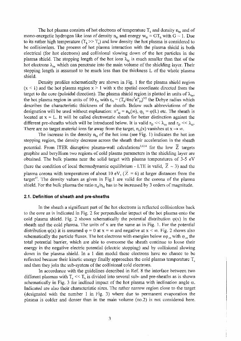
The hot plasma consists of hot electrons of temperature T11 and density n11e and of mono-energetic hydrogen like ions of density n11i and energy w11i = GT11 with G ~ 1. Due to its rather high temperature (Th >> TJ and low density the hot plasma is considered to be collisionless. The process of hot plasma interaction with the plasma shield is both electrical (for hot electrons) and collisional slowing down of the hot particles in the plasma shield. The stopping length of the hot ions A11i is much smaller than that of the hot electrons /c11e which can penetrate into the main volume of the shielding layer. Their stopping length is assumed to be much less than the thickness L of the whole plasma shield.
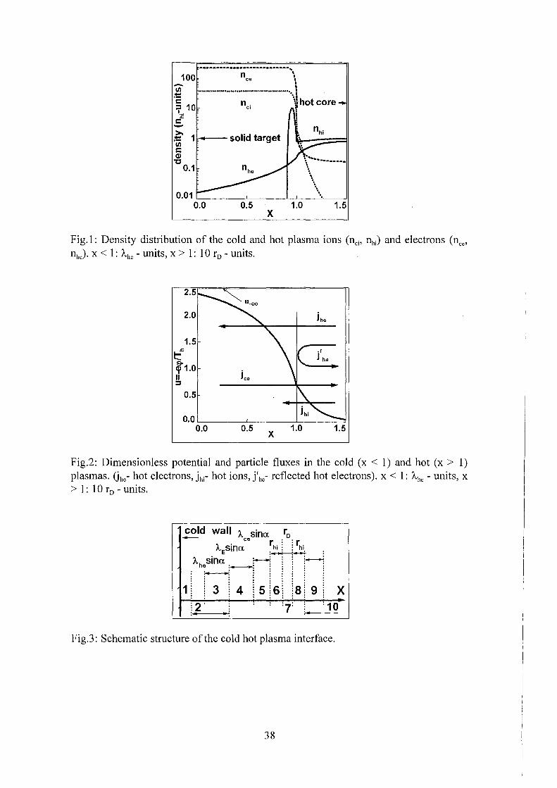
Density profiles schematically are shown in Fig. 1 for the plasma shield region (x < 1) and the hot plasma region x > 1 with x the spatial coordinate directed from the target to the core (poloidal direction). The plasma shield region is plotted in units of /c11e, the hot plasma region in units of 10 r0 with r0 = (T11/4ne2n"'11i)
112 the Debyeradius which describes the characteristic thickness of the sheath. Below such abbreviations of the designationwill be used without explanation: n"'11i = n11/oo), <pL = <p(L) etc. The sheath is located at x = L. It will be called electrostatic sheath for better distinction against the different pre-sheaths which will be introduced below. It is valid r0 << Ace and r0 << Aci· There are no targetmaterial ions far away from the target, nci(x) vanishes at x ~ co.
The increase in the density n11i of the hot ions (see Fig. 1) indicates the hot ion stopping region, the density decrease across the sheath their acceleration in the sheath
potential. From ITER disruptive plasma-wall calculations2'4
'14 for the low Z targets
graphite and beryllium two regions of cold plasma parameters in the shielding layer are obtained. The bulk plasma near the solid target with plasma temperatures of 3-5 eV
(here the condition of local thermodynamic equilibrium - L TE is valid, Z ~ 3) and the
plasma corona with temperatures of about 10 e V, ( Z = 6) at larger distances from the targd 5
• The density values as given in Fig.1 are valid for the corona of the plasma shield. Forthebulk plasma the ratio nc/n11i has tobe increased by 3 orders ofmagnitude,
2.1. Definition of sheath and pre-sheaths
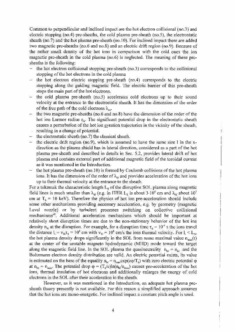
In the sheath a significant part of the hot electrons is reflected collisionless back to the core as is indicated in Fig. 2 for perpendicular impact of the hot plasma onto the cold plasma shield. Fig. 2 shows schematically the potential distribution <p(x) in the sheath and the cold plasma. The units of x are the same as in Fig. 1. For the potential distribution <p(x) it is assumed <p = 0 at x = co and negative at x < oo. Fig. 2 shows also schematically the particle fluxes. The hot electrons with energies below e<p_"' with <p_"' the total potential barrier, which are able to overcome the sheath continue to loose their energy in the negative electric potential ( electric stopping) and by collisional slowing down in the plasma shield. In a 1 dim model these electrons have no chance to be reflected because their kinetic energy finally approaches the cold plasma temperature Tc and then they join the sub-system of the collisional cold electrons.
In accordance with the guidelines described in Ref. 8 the interface between two different plasmas with Tc<< T11 is divided into several sub- and pre-sheaths as is shown schematically in Fig. 3 for inclined impact of the hot plasma with inclination angle a,
Indicated are also their characteristic sizes. The rather narrow region close to the target (designated with the number 1 in Fig. 3) where due to permanent evaporation the plasma is colder and denser than in the main volume (no.2) is not considered here.
3
Common to perpendicular and inclined impact are the hot electron collisional (no.3) and electric stopping (no.4) pre-sheaths, the cold plasma pre-sheath (no.5), the electrostatic sheath (no.7) and the hot plasma pre-sheath (no.10). For inclined impact there are added two magnetic pre-sheaths (no.6 and no.8) and an electric drift region (no.9). Because of the rather small density of the hot ions in comparison with the cold ones the ion magnetic pre-sheath in the cold plasma (no.6) is neglected. The meaning of these presheaths is the following: - the hot electron collisional stopping pre-sheath (no.3) corresponds to the collisional
stopping of the hot electrons in the cold plasma - the hot electron electric stopping pre-sheath (no.4) corresponds to the electric
stopping along the guiding magnetic field. The electric barrier of this pre-sheath stops the main part of the hot electrons.
- the cold plasma pre-sheath (no.5) accelerates cold electrons up to their sound velocity at the entrance to the electrostatic sheath. It has the dimension of the order of the free path of the cold electrons "-ce· the two magnetic pre-sheaths (no.6 and no.8) have the dimension of the order of the hot ion Larmor radius rhi· The significant potential drop in the electrostatic sheath causes a perturbation of the hot ion gyration trajectories in the vicinity of the sheath, resulting in a change of potential.
- the electrostatic sheath (no. 7) the classical sheath. - the electric drift region (no.9), which is assumed to have the same size 1 in the x-
direction as the plasma shield has in lateral direction, considered as a part of the hot plasma pre-sheath and described in details in Sec. 5.2, provides lateral drift of hot plasma and contains external part of additional magnetic field of the toroidal current as it was mentioned in the Introduction.
- the hot plasma pre-sheath (no.1 0) is formed by Coulomb collisions of the hot plasma ions. It has the dimension of the order of A,hi and provides acceleration of the hot ions up to their thermal velocity at the entrance to the sheath.
Foratokamak the characteristic length Ls of the disruptive SOL plasma along magnetic field lines is much smaller than Ahi ( e.g. in ITER Ls is about 3 ·1 04 cm and A,hi about 107
cm at Th = 10 ke V). Therefore the physics of hot ion pre-acceleration should include some other mechanisms providing necessary acceleration, e.g. by geometry (magnetic Laval nozzle) or by turbulent processes switching on collective collisional mechanisms 10
• Additional acceleration mechanisms which should be important at relatively short disruption times are due to the non-stationary behavior of the hot ion density nhi at the disruption. For example, for a disruption time -cd = 1 o-4 s the ions travel the distance Ii = vTitd = 104 cm with vTi = 108 cm/s the ionsthermal velocity. For Ii < Ls, the hot plasma density drops significantly in the SOL from some maximal value nmaxCt) at the center of the unstable magneto hydrodynamic (MHD) mode toward the target along the magnetic field line. In the SOL plasma the quasineutrality nhe = nhi and the Boltzmann electron density distribution are valid. An electric potential exists, its value is estimated on the base of the equality nhi = nmaxexp( e<p/Th) with zero electric potential <p at nhe = nmax· The potential drop <p = (Tk/e)ln(nh/n,nax) causes pre-acceleration of the hot ions, thermal insulation of hot electrons and additionally enlarges the energy of cold electrons in the SOLafter their acceleration in the sheath.
However, as it was mentioned in the Introduction, an adequate hot plasma presheath theory presently is not available. Forthis reason a simplified approach assumes that the hot ions are mono-energetic. For inclined impact a constant pitch angle is used.
4
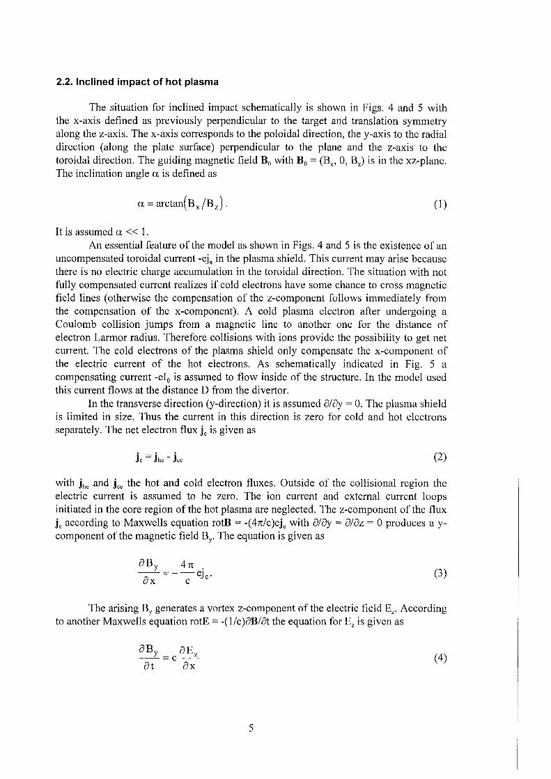
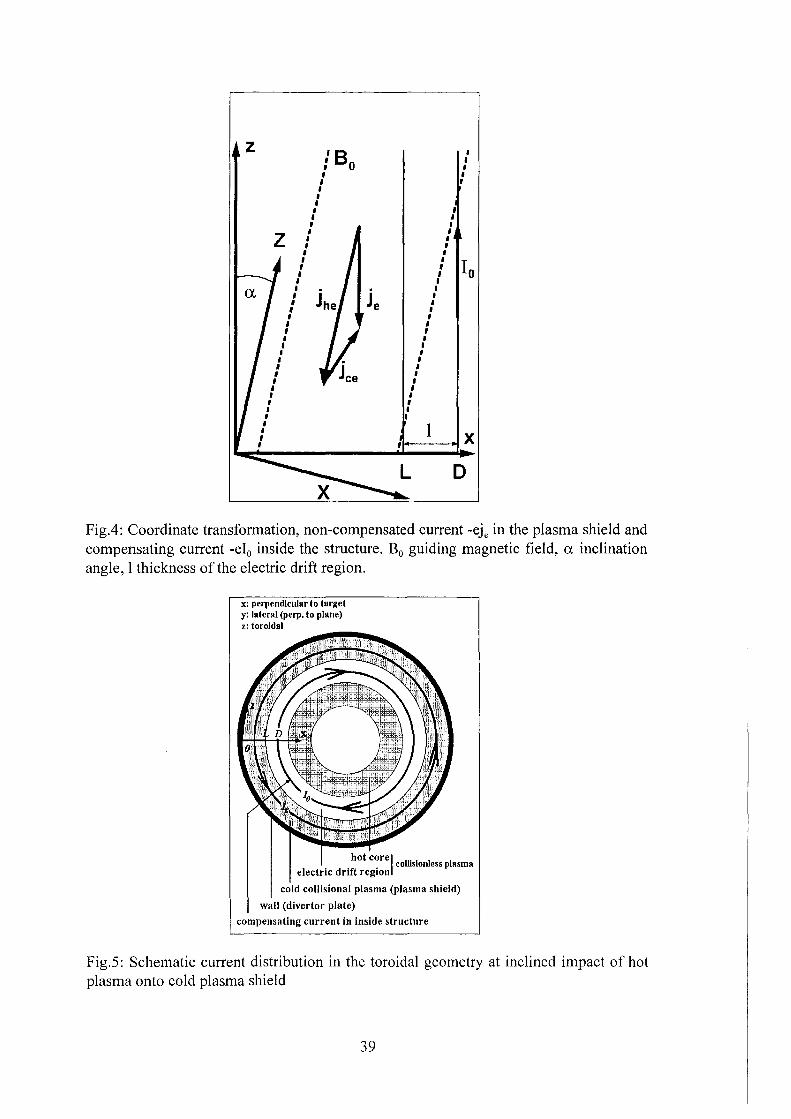
2.2. lnclined impact of hot plasma
The situation for inclined impact schematically is shown in Figs. 4 and 5 with the x-axis defined as previously perpendicular to the target and translation symmetry along the z-axis. The x-axis corresponds to the poloidal direction, the y-axis to the radial direction (along the plate surface) perpendicular to the plane and the z-axis to the toroidal direction. The guiding magnetic field B0 with B0 = (Bx, 0, Bz) is in the xz-plane. The inclination angle a is defined as
(1)
It is assumed a << 1. An essential feature of the model as shown in Figs. 4 and 5 is the existence of an
uncompensated toroidal current -eje in the plasma shield. This current may arise because there is no electric charge accumulation in the toroidal direction. The situation with not fully compensated current realizes if cold electrons have some chance to cross magnetic field lines ( otherwise the compensation of the z-component follows immediately from the compensation of the x-component). A cold plasma electron after undergoing a Coulomb collision jumps from a magnetic line to another one for the distance of electron Larmor radius. Therefore collisions with ions provide the possibility to get net current. The cold electrons of the plasma shield only compensate the x-component of the electric current of the hot electrons. As schematically indicated in Fig. 5 a compensating current -ei0 is assumed to flow inside of the structure. In the model used this current flows at the distance D from the divertor.
In the transverse direction (y-direction) it is assumed 8/ay = 0. The plasma shield is limited in size. Thus the current in this direction is zero for cold and hot electrons separately. The net electron flux je is given as
(2)
with jhe and jce the hot and cold electron fluxes. Outside of the collisional region the electric current is assumed to be zero. The ion current and external current loops initiated in the core region of the hot plasma are neglected. The z-component of the flux je according to Maxwells equation rotB = -(4n/c)eje with 8/ay = a!az = 0 produces a ycomponent ofthe magnetic field BY. The equation is given as
8By 4n . --=--eJ. ax c e
(3)
The arising BY generates a vortex z-component of the electric field Ez. According to another Maxwells equation rotE= -(l/c)8B/at the equation for Ez is given as
aBY_caEz --- --
at ax (4)
5
Ez influences the stopping of hot electrons in the plasma shield. B0 is constant because there exists only a z-component of the current. The assumption a;ay = 0 was introduced to simplify the problern removing those features which are not principally changing the main results.
A simple argumentation for the existence of the net current is the following: assuming je = 0 then the flux of cold electrons has to compensate the flux of the incoming hot electrons. Due to Ohms law the cold electron current in toroidal geometry produces both a potential EP = (Ex,Ey,O) and a vortex electric field Ev = (O,O,Ez). The vortex electric field has closed field lines and generates the magnetic field BY' which can be created only with je :f. 0.
The cold plasma in the collisional region 16 obeys the usual hydrodynamics equations 17 which are applied below in the simplest way in order to arrive at a simple solution. From Ohms law given as
with cr=e2ncetc/me the electric conductivity, 'tce the momentum relaxation time in the collisions of cold electrons with ions and from Eq. (2) it is clearly seen that the assumption je = 0 and the motion of hot electrons along field lines result in the electric field directed along the magnetic field thus formally confirming the simple argumentation. Hence for inclined impact the self consistent non stationary process of formation of electric and magnetic fields has to be included. The full self-consistent model for inclined impact is presented in Sec. 5.
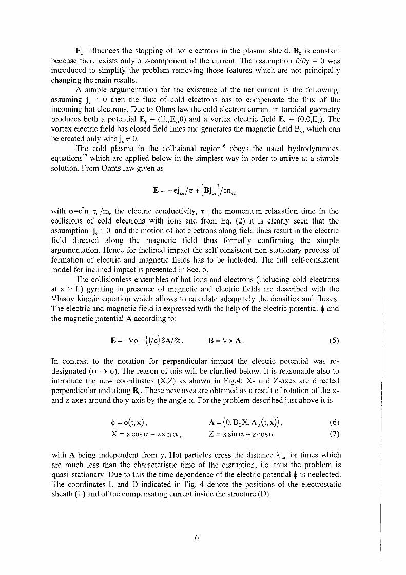
The collisionless ensembles of hot ions and electrons (including cold electrons at x > L) gyrating in presence of magnetic and electric fields are described with the Vlasov kinetic equation which allows to calculate adequately the densities and fluxes. The electric and magnetic field is expressed with the help of the electric potential ~ and the magnetic potential A according to:
E =-V'~ -(lfc) 8Ajat, B=Y'xA. (5)
In cantrast to the notation for perpendicular impact the electric potential was redesignated ( <p 0 ~ ). The reason of this will be clarified below. It is reasonable also to introduce the new coordinates (X,Z) as shown in Fig.4: X- and Z-axes are directed perpendicular and along B0• These new axes are obtained as a result ofrotation ofthe xand z-axes around the y-axis by the angle a. For the problern described just above it is
~ = ~(t,x), X= xcosa- zsina,
A = ( 0, B0X, Az(t, x)), Z = xsina + zcosa
(6)
(7)
with A being independent from y. Hot particles cross the distance A11e for times which are much less than the characteristic time of the disruption, i.e. thus the problern is quasi-stationary. Due to this the time dependence of the electric potential ~ is neglected. The coordinates L and D indicated in Fig. 4 denote the positions of the electrostatic sheath (L) and of the compensating current inside the structure (D).
6
3. MATHEMATICAL DESCRIPTION FOR PERPENDICULAR IMPACT
To tackle this problern the condition of zero electric current is used in the plasma shield and the Poisson equation for E =- dcp/dx in the sheath. For the cold pre-sheath the quasineutrality condition is used. In terms of particle fluxes the condition of zero current ts gtven as:
(8)
The Poisson equation is written as:
dE/dx = 4neön with ön = nhi + Znci- nhe- nce. (9)
The particle fluxes schematically are shown in Fig. 2. j 11e is the net flux of the hot electrons, L is the flux of the cold electrons that arises in the plasma to compensate j 11c
and the flux of hot ions jhi· As to the flux of cold ions a coordinate system with zero value of this flux is chosen. Fig. 2 also shows the flux f 11e of electrons which are reflected at the electrostatic potential.
The boundary condition for Eq. (9) is E = 0 at x = oo. From this it follows for the infinity dE/dx = 0 and from Eq. (9):
at x = oo (10)
lf the Right Hand Side (RHS) of Eq. (9) could be fully determined and would satisfy cond. (1 0) then Eq. (9) could be solved. But ön depends on the unknown quantities of <p_
"' and <JJL which have to be found from additional boundary conditions. To simplify the problern the smallness of the Debye radius is used. At r0 ~ 0 constant potential <p at both sides of the sheath is used. Therefore in the approximation r 0 ~ 0 the two additional boundary conditions:
E = 0, X= L, (11)
(12)
are to be satisfied. The condition (11) has accuracy of characteristic value of E for the cold pre-sheath and is allowed to be used only for the solution of Eq. (9) in the sheath. Condition ( 12) should be valid everywhere outside of the sheath. L is the coordinate of the interface between the sheath and the cold pre-sheath. The conditions (11) and (12) at x = L are the boundary conditions at '-oo' on the r0 scale (for more details see Ref. 9).
Multiplying Eq. (9) by E and integration over the interval (x,+oo) results in:
(13)
with zero charge in the sheath given as:
(14)
7
The potential profile in the sheath is obtained from the expression:
( )-1/2
x = ff 8nef0• &(qy") dqy" dqy'
21PL tp (15)
with x = 0 at <p = <pL/2 in the local frame of the sheath. The bot electrons are Maxwellian distributed at infinity x = co. Their density and
flux can be calculated for arbitrary x, because due to their uncollisionality they keep the Boltzmann distribution at any cross-section:
nhe = exp(eqy/Th) C~fM (v) dv,
jhe = exp( eqy/Th) C~vfM (v) dv .
(16)
(17)
The one-dimensional Maxwell distribution function of electron velocity v is given by the expression
(18)
The upper boundary vm =(2e(<r-<rm)/met2
ofthe integration region in Eqs. (16)
and ( 1 7) is established by the fact that there are no hot electrons coming back from the slowing down region at x < L: those electrons would have kinetic energies exceeding the corresponding potential difference: me v2/2 > e( <p(x)-<prn). For <p ;:::: <!>L it is used <rrn = <I'L· For the region <1'-co s; <p s; <!>L it is valid vm = 0, i.e. thus it is assumed that at Tc << T11 hot electrons are captured by the cold plasma at the moment of their stopping. Calculating the integrals in Eq s. ( 16) and (17) yields:
with vThe = ~2Th/me the thermal velocity of the hot electrons. The complementary
error function is defined as
(erfc(0)=1, erfc(co)=O, ifz>> 1 then erfc(z)';:;je-z2/fitz). The factor 8 takes into
account the attenuation of the hot electron flux in the cold plasma due to Coulomb collisions. A rigorous approach for the consistent calculation of Coulomb scattering and slowing down tagether with electrical stopping would be a rather complicated task which will not be carried out here. Instead of this and for the sake of simplicity the Coulomb attenuation is qualitatively taken into account by the exponential factor 8 given as:
8 = exp(min(ü,(x- L)/A-hc))· (21)
8
The hot ions are assumed to be mono-energetic having velocity v"\; and density n'\; at infinity. Due to acceleration in the electric field hot ions increase their velocity vh; in the region of the electric potential outside of the slowing down region thus reducing their density as it follows from the flux conservation equation:
(22)
From the energy conservation equation for hot ions it follows:
(23)
with m; the mass of a hot ion and whi = 1 mi( vhi t. Calculating vh;(x) from Eq. (23):
(24)
the density ofhot ions is obtained from Eq. (22) and Eq. (24):
00 ( I 00 )-112 n hi = n hi 1 - e<p w hi . (25)
The flux of cold electrons both in the collisional and the collisionless region is defined as
Jce = nce V ce (26)
with vce the velocity of the cold electrons. Due to the presence of an electric field in the collisional region the cold electrons move from there to the edge of the shielding layer where the rate of collisions with cold ions decreases but meanwhile the electric field accelerates them. Upon reaching the edge the electrons lose the balance of electric and friction forces. After this they are accelerated and collisionless move to infinity. To describe their behavior the usual hydrodynamic motion equation17 is used:
(27)
with 'tce="AjvTce• vTce=(2T/m0 )112 the thermal velocity of cold electrons. Their free path is
given according to expression
(28)
with A,q ~ 1 0 the value of the Coulomb logarithm which is assumed to be constant. The loss of balance corresponds to the region where in Eq. (27) the values of the
terms inertial mevcedvc/dx and pressure gradient (T/nce)dnjdx equal the values of both other terms. The equality of the electrical and the friction term in the collisional region expresses the momentum balance and is Ohms law
9
- ejce = crE . (29)
In the collisionless region friction and cold electron pressure gradient and for simplicity the thermal distribution of cold electrons are neglected. Hence the inertial term is equal to -eE, i.e. cold electrons obey the energy conservation law:
I 2 oo 2 m e V ce - ecp = W ce (30)
with w: = 1 me( v~e t. Due to Eq. (26) and Eq. (30) the density and velocity of the
cold electrons in the collisionless region are obtained as:
00 ( I 00 )1/2 V ce = V ce 1 + ecp W ce '
00 ( I 00 )-112 n ce = n ce 1 + ecp W ce ·
(31)
(32)
The density distribution nc;(x) of the cold ions is a solution of some general hydrodynamic problern for the target material plasma expansion. This is calculated outside of the presented work2
• Thus in the shielding layer nc;(x) is considered to be a given function of x. As was mentioned above the velocity of the cold ions is assumed to be zero, i.e. their flux is zero, too. Due to small velocities of the cold ions in comparison with electrons and hot ions the consideration for the cold ion flux can be neglected. The structure of the electric field is determined by the relative position of electrons to ions. Owing to their large velocities the fast particles are able to adjust themselves to the current distribution of the cold ions immediately. This quasi-stationary change of the electric field follows from the relatively slow expansion of the shielding layer. As it was mentioned above the coordinate system of the cold plasma edge is considered as a frame of the problern and the problern is analyzed mathematically for a relatively small depth of electrical pre-sheath into the shielding layer in comparison with the layer thickness. The inertial term in the hydrodynamics motion equation vanishes automatically in the chosen frame near the boundary of the whole MHD problern for the plasma shield. Therefore in the collisional region near the edge x = L of the sheath it is still allowed to consider cold ions as being in rest and stationary. They are described by the following equations:
-(Tc/nci)dnci /dx + ZeE + F = 0, (33)
Here F is the force of friction with the cold electrons. In the region of the cold plasma edge at L-x ~ r0 the main force acting on the cold ions in the sheath becomes the electric field. Collisions can be neglected and the electric field determines the profile of the cold ion density. By this way neglecting F in Eq. (33) the Boltzmann density distribution of cold ions in the sheath is obtained:
(34)
10
From Eq. (34) formally follows nc;(oo) =F 0 but this exponentially smallleakage of cold ions to infinity will be always neglected.
It should be noted that in any case the cold ion pressure is confined by some part of the hot plasma momentum but at the cold plasma edge the confinement is realized by the self consistent electric field. In other words the pressure balance at the edge results from the momentum of the hot electrons and the reflection of the cold ions from the sheath and from the reaction force due to acceleration of cold electrons and hot ions in the sheath.
The necessary condition for the existence of the sheath when approaching r0 ~0
is a singularity of the solution of the quasineutral hydrodynamics problern at x = L. i.e. formally it should be E = oo at x = L. There is no confusion with the condition ( 11) because the point x = L is chosenasthat of small gradient for the r0 scale problern and simultaneously as that of large gradient for the 'Ace scale problem. The problern is described with the four equations (12), (27), (29), (33) for the four unknown variables nce' nci, vce' E at the given electric potentials <p_", and <pL' Rewriting Eq. (33) yields
- -(T/nc)(dnJdcp)+Ze+F/E = 0, hence dnjdcp = -Zenc/Tc for E = oo at x = L. This is consistent with Eq. (34). lf Tc<< T11 then the densities of hot ions and electrons in the collisional region will be small in comparison with those of the cold plasma. Then from
the quasineutrality condition (Eq. (12)) it is obtained nce :::; Znci at X ~ L. With this simplification it is obtained from the three other equations tagether with Eq. (8) and Eq. (20):
(35)
The term on the RHS being of small value takes into account the dependence of j 11e on x at <p < <pL. Taking into account the reflection of hot electrons from the region of strong electric field near x = L then the RHS is becoming still smaller. Due to the smallness of the RHS and due to the inequality dnc/dcp =F 0 the following value for the velocity vceCL) is obtained:
L V ce = gvTce (36)
with g2 = ( Z + 1 )/2 Z. Hence cold electrons enter the sheath with their isothermal so und velocity. At the interface between the cold and the hot plasma it is not necessary to introduce a reversed potential drop of value of Tc to artificially prevent penetration of cold electrons into the sheath as was introduced in Ref. 11. The potential cp(x) keeps its monotonic behavior everywhere in the shield.
There are no hot ions in the main volume of the cold plasma. It is penetrated only by hot electrons. The stopping of ions brings momentum flux into the cold plasma. From the pressure balance between the cold plasma and this momentum flux:
(37)
the density ofthe cold plasma ions in the main volume is obtained according to:
11
(38)
This density is attributed to the parts of the shielding layer which are penetrated by hot electrons. The size of this volume is estimated by the collision length A11e of the hot
electrons in the cold plasma. A-11• is obtained from Eq. (28) using n~;"' and T11 instead of nci and Tc there, as
(39)
4. SOLUTION FOR PERPENDICULAR IMPACT
4.1. "The collisionless infinity"
After the derivation of the full physical description and the mathematical notation the problern is solved at first for Ahe << L. The aim is to find finally the fluxes of hot electrons and ions before they are slowed down in the shielding layer as well as the boundary condition for the solution of the hydrodynamics problern for the cold plasma.
Before seeking the solution it is noticed that from cond. (1 0) and Eq. (19) it follows for q the ratio ofhot electron to hot ion density at infinity (q = n"'11/n"'11;):
( 00 I 00 )( I c--)-1/2 q = 1- nce nhi 1- 2erfc-yuL (40)
with uL =-e<pL/T11 • The values n'\e and n"'11; need not to be equalized as was done in Ref. 11 where the value of the electrostatic potential in the sheath was calculated as uL ::::; 1.6+ 1. 7. The constraint q = 1 closes the mathematical description without the necessity to use the emitting properties ofthe cold substance at it's boundary. Using this equalization immediately allows to determine from Eq. (40) the density of electrons at infinity:
(41)
and therefore the electron emission coefficient at the boundary of the cold substance:
(42)
Hence the emission coefficient would be defined only by the dimensionless value uL of the electrostatic potential: ie ::::; 21--/n while uL > 1. In reality the emission coefficient depends on the parameters of the cold substance. For example, if the substance is cold enough then the emission coefficient tends to zero (ie ~ 0). It is well known that in this case there exists a definite value of uL (uL ~ 3 depending on the model). In the real plasma shield ie :f. 0. lf there is no reverse flux of cold electrons to infinity (n"'ce = 0) then it is impossible to satisfy Eq. ( 40) while equalizing n"'11e and n"'11 ;.
12
It is not adequate to consider "the collisionless infinity" as true because this "infinity" is not the physical infinity of the whole problern (it is only '+oo' in the r0 -scale ). Only if there exists local thermodynamic equilibrium at infinity then it is allowed to equalize the densities as mentioned above. The existence of some additional electrostatic potential between the sheath and the far distant collision area of the hot plasma, i.e. a pre-sheath has to be assumed. This potential also accelerates the ions coming from far away to the region of '+oo' and decreases the density of hot electrons there, thus providing the parameter to disconnect the n"'he and n"'hi· This pre-acceleration of the Maxwellian ions makes it easier to accept the assumption of considering the hot ions as mono-energetic beam. Additionally collisions which change the distribution of particles can influence the value of q. Therefore the problern of potential calculations can only be solved adequately if an analysis ofthe pre-sheaths is included.
4.2. Physical parameters and solution of equations
Eq. (8) of zero current at x < L is used to obtain the electrostatic potential in the collisional region where hot ions are absent owing to their stopping close to x = L. Using Eqs. (20) and (40) Eq. (29) is transformed into:
uj~=O = UL (43)
with u = -ecp/Th, ~ = (L-x)/A.he· The spatial coordinate x was transformed to the dimensionless quantity ~· The same was done with the potential. Due to this procedure it is possible to get the important dimensionless parameter K with
(44)
K determines the value of the electrostatic potential for the collisional region. From Eq. (43) the potential in the collisional region where the hot ionsarealready stopped is obtained as long as ~ << 1. Due to the rather short distance of the stopping of the hot ions it is possible to neglect the potential difference between the edges of the slowing down interval of the hot ions. Below an estimation of the ratio A-"/Ahe is given. Hence it is obtained:
(45)
(u_"' = -e<p_"'/T"). This solution doesn't describe the singularity at x = L. This problern is discussed below.
The quasineutrality conditions (10) and (12) after using Eqs. (19), (24), (25), (31 ), (32), (34), and Eq. ( 40) and transformation to dimensionless parameters take the form
qkL + qe = 1,
lqe-uL +qeO/y=(l+uL;ori/2 +qj
13
(46)
(47)
with kL = k(uL), qe = n"'jn"'h;, q; = nLc;ln"'tt;" y = v\/vThe' G = w"'11 /T1p n = (y2+uL) 112 and k(u) as given in Eq. (19). For G it is assumed G ~ 1. From the condition of zero current at x > L (Eq. (8)) and using Eq. (20), Eqs. (22), Eq. (26) it is obtained:
(48)
with y = (m/m;)112• For the sake of simplicity small contributions of ions to the current
are neglected (y = 0). The equation of the momentum balance of the sheath (14) after being transformed in the same manner is given as:
with 8 = (T/T11)112 << 1.
Thus there is a closed system of four equations ( 46) - ( 49), for the four unknown variables q;, qe, q, uL. The dimensionless velocity y of cold electrons at x = L is obtained from Eq. (36): y = 8g.
To simplify the solution of this system the smallness of 8 is used. Due to y ~ 8 the expression y2 + uL is replaced by uL andin Eq. (47) the rather small contributions of hot electrons (the term ~q) and hot ions (the term with G) to the quasineutrality at x = L are neglected. Therefore it is obtained for q;:
(50)
qc is obtained from Eq. ( 48). For y = 0 it is obtained:
(51)
q is obtained from Eq. (46) as:
(52)
Now all values are expressed via uL' uL is obtained from Eq. (49). Again neglecting small contributions Eq. (49) is written as:
(53)
For uL >> 1 it is obtained from Eq. (53) u ~ 1/4G. This result corresponds to G << 1. lf the value ofuL decreases then the RHS ofEq.(53) approaches zero. Hence a solution for uL exists formally for any positive value of G. Forthis it must be valid uL > um with um given by the condition that the RHS ofEq. (53) is zero at uL = U111 :
(54)
14
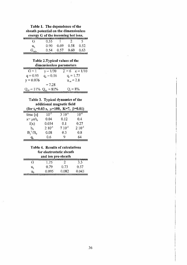
This equation was solved iteratively starting with um = 1 in the RHS. As a result it is obtained uL ~ ~1 ~ 0.49 for G ~ oo. Values of uL for sorne G values as obtained frorn Eq. (53) are given in Table 1. Concerning the rninirnurn possible value of G (Gmin) see the discussion below on the Bohm criterion.
Now the features of the potential distribution in the collisional region can be described. Substituting all known values into Eq. (44) it is obtained:
(55)
With 8 as srnall pararneter (K >> 1) it is obtained frorn Eq. (45) U_00 ~ -ln8 >> 1. Frorn this it is concluded that at the depth !arger than A11e the change of the electric potential in the collisional region is becorning srnall. Therefore the influence of the electric field on the stopping of electrons in the rnain volurne can be neglected. But due to the large value of u_"" the rnain part of the hot electrons is electrically stopped in the relatively narrow region near the edge of the shielding layer. Then they corne back as reverse current of cold electrons depositing their energy by Ohrnie heating.
A rnore adequate description of this electric stopping region needs rnore details such as consideration of the Knudsen layer between the collisional region and the sheath to take into account escaping of cold run-away electrons frorn the cold pre-sheath. Additionally reflection of hot electrons frorn the electrical pre-sheath should be considered. In this case the inclined rnotion of hot electrons with respect to the guiding rnagnetic field has to be taken into account. Such a rnore cornplicated description is still lacking and could be perforrned in a next analysis of the interface problern between the cold and the hot plasrna.
Now an upper estirnation for the ratio ofthe hot ion stopping length A11i to the hot electron stopping length A11e is given. The equation of slowing down of hot ions by cold electrons is given as 18
:
(56)
with 11 = 6Tt/I(A11encirnt2), rn1 the rnass of the cold ion, v\i = yvThe(G+uL) 112
, vc ~ vTceY213•
Integrating this equation over the interval L-A11i < x < L yields:
and then:
(57)
Hence the assurnption A11i << A11e is correct only for srnall 8 (practically 8 < 0.3). The behavior of the electrostatic potential in the interval 0 < s < s' with
s' = A-1JA-11e can be described by Eq. (45) as long as s > "-ce(L)/A-11e ~ 8\ because the hot ion current is negligibly srnall and the coefficient of electrical conductivity cr doesn't depend on the density. At s:::; 83 (i.e. at the distances frorn the sheath cornparable to free
15
path of cold plasma particles) all terms in Eqs. (27) and (33) are significant. But to account for all of them is not enough for a spatial resolution of the above mentioned potential singularity at the sheath. As it is usual for hydrodynamic problems it is necessary to have in addition some dissipative terms ( describing viscosity and/or heat conduction) to get the spatial dependencies near the singularity at x = L. It is not necessary to analyze this structure here because the only characteristic value of energy in the region of singularity is Tc, i.e. which adds only a negligibly small correction of the order of T/e to the potential cp(x). The calculated spatial dependence of the dimensionless potential u(x) is shown in Fig. 2.
4.3. Energy deposition into the plasma shield
Finally the energy fluxes Qe0<0> and QeL of the hot electrons to the main volume
and to the electrical pre-sheath and the energy flux Qi deposited into the cold plasma by
the hot ions are calculated without attenuation factor 8. The flux Q~O) transported by
electrons reaching the points u;?: uL is given by the integral:
Qi is given by the expression:
Expressing QeLand Qi in terms of Qeo = Q~0)(u_oo) it is obtained:
(58)
(59)
(60)
(61)
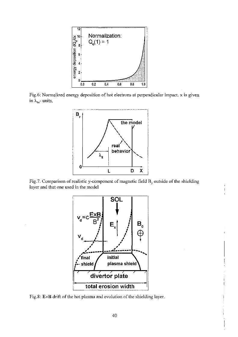
With the factor 8 no electrons are reaching the potential region of u ~ u_"" Therefore Qeo gives an estimation of the net Coulomb stopping contribution. QeL provides a rather correct value of the net electrical stopping contribution as long as the main part of the electrons is absorbed in the region of size less than A,he· The distribution of the whole hot electron energy deposition in accordance with Eq. (43) is given as:
d Q/ dx=( du/ dx )d(8Qe (O))/ du.
In accordance with Eq. (45) dQ/dx is proportional to ((K+1)e;-K)"2• This is shown in
Fig. 6. The width of the electrical pre-sheath A,E can be defined as the distance of half absorption, corresponding to the value of u given as Qe(u)/QeL = 0.5. Then it follows from Eq. ( 45) at K >> 1: A,E:::::: A-1,/K.
Values for different parameters discussed in this section are given in Table 2 for
G = 1, y = 1/70, Z = 6, E = 1110 to demonstrate their characteristic size. The energy deposition into the main volume is K times smaller than into the electrical pre-sheath.
16
The energy deposition of ions at G ~ 1 is practically of the same order as Qeo (ions are important from the point ofthe momentum transfer). Fig. 1 rather qualitatively describes the density distributions for the mentioned case. E.g. it shows in addition the peak of the density of the hot ions arising from the stopping of the ion beam. The decrease of the cold ion density in the sheath as shown in Fig. 1 is not so abrupt as it should be in accordance with Eq. (34).
The whole electron energy flux Qew is obtained by subtracting the flux of cold electrons Qce = Yzme[nc.(vce/Jx~"' from Qe(O)(uL). From Eqs. (51) and (58) it follows:
Comparing this expression and the heat flux without the sheath Qew(O) the factor of the electron heat insulation by the sheath is obtained as K = exp(-uL)(l-uL/2). For example, in accordance with Table 1 this factor for G = 1 is obtained as K = 3 .1.
4.4. The Bohm criterion
The Eqs (18) and (19) for the hot electron distribution function and their density are valid rigorously only if the electric potential depends monotonically on x, otherwise regions in the velocity space v are arising which cannot be accessed by the collisionless hot electrons. Moreover a non-monotanie situation can result in the development of plasma instabilities. Therefore it should be established a criterion for the monotonic behavior of the potential.
Substituting Eqs. (19), (25), (32) and (34) into Eq. (13) and converting to dimensionless variables it is obtained for the potential in the limit 8 ~ 0:
with Cl> oc (du/dx)2• Requiring now a rigorously positive value of Cl> for the limit x ~ oo
(at u ~ 0) expressed as minct> > 0 results in the Bohm criterion. The required condition is a necessary but not a sufficient condition for the monotonic behavior. At u ~ 0 Eq. (62) transforms into
(63)
i.e. Cl>> 0 while the expression in the brackets is positive. Introducing Eq. (51) and (53) for qe and uL results in a lower limit ofthe hot ion energy Gmin given as:
The calculated minimum value of G (GmiJ with uL satisfying Eq. (53) is 0.5. According to Table 1 it is seen that all points listed there are satisfying the Bohm criterion.
From Eq. (15) it is obtained:
17
and thus the asymptotic value ofu at x __, oo is given as:
u cx: exp(- ~<1>"( 0) x/r0 )
Hence it follows that when approaching the margin ofthe stability (i.e. <1>" __, 0) the sheath penetrates infinitely into the hot plasma.
5. INCLINED IMPACT OF HOT PLASMA
5.1. Collisionless region with inclined impact
(65)
(66)
At early times the additional magnetic field BY (see Eq. (3)) is much less than I ß 0 I. Therefore the perturbations Az with BY = -8A/&x are neglected. But it is to remind that Ez = -(1/c)8A/at substantially effects the stopping ofthe hot electrons.
The behavior of collisionless hot particles in non-stationary fields is described by the Rarnilton function H19
• H i.s given according to:
with p = (Px, Py• Pz) = mv + ( ejc )A the canonical momentum, v the particle velocity.
The particles are described with the distribution function f(t,x,z,p). Symmetry along the y-direction is assumed. Symmetry along the z-direction conveniently will be used later. The value of the distribution function is constant along the trajectory of a collisionless particle, i.e. f is the motion integral. Its time derivation along the particle trajectory is zero:
with {H,f} the Poisson brackets. Eq. (68) is the Vlasov kinetic equation for the distribution function. From the
independence ofH from y follows {H,py} = 0. Todetermine the three component vector p for each point (x,z) the function f should be expressed via three motion integrals. Their values are to be fixed by the initial conditions of the trajectories, i.e. f should depend on Py and some two additional motion integrals. From the fact that the time derivation of H along the particle trajectory is equal to its partial derivation the following motion integral is obtained:
(69)
Therefore along the trajectory the following expression remains constant:
18
H' =H-eft E v dt' -OC) z z (70)
i.e. H' is the second integral. As will be shown below the integral in Eq. (70) is mainly a function of x. For a << 1 a third motion integral can be found. It is the adiabatic invariant. Its value remains constant along the trajectory (small oscillations of the order of a are neglected). The expression for the adiabatic invariant considering H' in the new XZ-frame, neglecting small Az and assuming Z constant during one gyration cycle is obtained. Hence the canonical momentum p
11 = Pxsina + pzcosa corresponding to Z is
also constant. Therefore H' can be considered to be the Barnilton function of some onedimensional system oscillating along the X-axis. Then in accordance with Ref. 19 the adiabatic invariant can be expressed by the integral:
I= (wj n)J~m.ax PxdX mm
(71)
with ro = eBofmc the gyration frequency and Px the canonical momentum corresponding to the X-coordinate. Px is given according to
r1 = 2m(H _1_- etp)- (Py- mwxt with H _1_ = H'- p1f /2m and
(72)
(73)
Xmin and Xmax are the roots of the equation Px = 0 (stopping points of oscillation along X). In Eq. (73) an 'effective potential' <p is introduced which is assumed to vanish at X-) +oo. As will be shown below the effective potential in case of inclined magnetic field plays the same role as the electric potential <p in case of perpendicular impact. This is the reason for using the same designation <p.
The calculation of the integral in Eq. (71) at <p = 0 yields I = H _j_· The stopping points are
From this the value of Py is determined by the coordinate XC = (Xmin+ xmaJ/2 being the transversal projection of the effective center of the particle trajectory ('the leading center'): Py = mroXc (this is the formal definition of Xe). From the symmetry along the z-direction follows that the distribution function doesn't depend explicitly on pY: f=f(H' ,I). Otherwise it would depend on Xc, hence in accordance with Eq. (7) on the zcoordinate ofthe leading center at fixed x-values.
Density and flux ofparticles are expressed according to:
n = ffdv, j = fvfdv. (74)
The distribution function of the Maxwellian hot electrons of temperature Th normalized to the core electron density n"\e depends explicitly only on H':
(75)
19
Such an expression for fhe is valid only for the trajectories of particles coming from the region x = +co (including the part of trajectories after possible reflection from the effective potential). The effective potential is assumed to be a monotonically increasing function of x. Then there should exist additional trajectories originating at x = -co (in the electrical pre-sheath) but there are no closed ones. If all trajectories would be populated and would have the same Maxwellian distribution function (see Eq. (75)) then Eq. (74) could be integrated over all the trajectories using Eq. (75) for arbitrary velocities resulting in the Boltzmann density distribution: nhe = n"'heexp( e<p/Th). Because there is no hot electron reflection from the region <p(x) < <pL the trajectories are unpopulated if electrons are coming from the electrical pre-sheath ( <J>L is the effective potential at x = L). It is not allowed to integrate in Eq. (74) over the velocities belanging to those trajectories.
To determine the empty domain ~~e = 0 of the electron velocity space the adiabatic invariant I as defined in Eq. (71) has tobe calculated. This can be done if it is assumed that the electron Larmor radius r Lhe is much less than the minimum characteristic length ofthe effective potential change given by the Debyeradius r0 . That is rhe << r0 where rhe = vTh/roe, roe = eBofmec. Below this assumption always is used.
Hence the change of potential can be neglected at Xmin < X < Xmax• and from Eq. (71) it is obtained I= H.1 + e<p. From this it is seen that the adiabatic invariant is the kinetic energy ofthe transverse motion mev}/2 with v} = v/ + v/. Therefore the only value that changes in the course of the motion is the velocity component v
11 = p
11/mc
parallel to B0• The energy conservation is given as
(76)
The transverse part of the electron energy remains constant along the trajectory. Therefore integration over Vx and vY in Eq. (74) can immediately be performed with the Maxwellian function for electrons (see Eq. (75)). By this way the same Eqs. (19) and (20) as for the case with perpendicular impact as functions of the effective potentials <p and <pL are obtained. The attenuation factor (see Eq. (21 )) is changed accounting for the inclination of hot electrons with respect to the x-axis:
8 = exp(min(O,(x- L)j'Ahe sino:)). (77)
The other species of collisionless particles are cold electrons. They are accelerated in the sheath. Their density nce and flux ic in Z-direction is calculated also using Eq. (76) but neglecting the relatively small value of the initial kinetic energy of the cold electrons at <p = <J>L· Due to the conservation of the adiabatic invariant it is used v .l =0. The distribution function of the cold electrons is written as
with the normalization constant Ce obtained from Eq. (74), and the Dirac 8-function:
b'( V) = [ 0, V :;C 0; co, V = 0],
20
From this the Eqs. (31) and (32) for nce and vce = jc/nce with W 00ce = -ecpL are obtained. Eq. (73) is transformed at vz < 0 into:
(dz' = vzdt' ). (79)
Due to the small oscillation amplitude along x the x'-coordinate in Ez is replaced by that of the leading center xc. As it is belanging to the magnetic field line, it is valid xccosa- z'sina = const. From this it is obtained neglecting the difference in x and xc:
(80)
Eq. (80) is valid if the shift of the x-location of the particle during a gyration cycle is small (i.e. the conservation of H' is valid with a small oscillation). It will be shown that even for hot ions Eq. (80) is valid also in the rather narrow vicinity of the sheath x ~ L ± r11i (i.e. in the ion pre-sheath, where r11i = v"'11/coi, coi = eBofmic ). The analysis of the ion pre-sheath is completed in Sec. 4.
Now the collisionless transition region at x > L + r11i defined as the electric drift region in Sec. 2.1 will be analyzed keeping in mind the connection between the core and the ion pre-sheath. The incoming flux of hot ions is assumed to have the density n"'hi at x = +oo, definite ion energy H0 and the pitch-angle defined as the angle 80
between the direction of B0 and the ion velocity vector v. For ions I = I0 = H0sin280 ,
m = mi. As distribution function it is obtained:
(81)
For I= H1 - e cp Eq. (81) for small Larmor radius transforms into:
(82)
After substitution of Eq. (82) into Eq. (74) the Eqs. (25) and (26) are obtained for the hot ion density nhi and the velocity v11i = j 11 /n11i parallel to the Z-axis with cp the effective potential and w"'11i = H0cos280•
As it was mentioned in Sec. 2.2 it must be valid je = 0 at x > L, i.e. in accordance with Eq. (3) there exists a spatially constant magnetic field BY = B\. The x dependence of BY is shown schematically in Fig. 7. In reality owing to the limited size of the vapor shield in y-direction such a magnetic field should gradually vanish in the electric drift region far away from the current conductor location in the vapor shield. For the sake of simplicity it is assumed here that the field is vanishing abruptly due to some artificial z-directed electric current -ei 0 which compensates the current of the shield and which is located at x = D (see Fig. 5). The distance 1 = D - L is assumed to be of the order of the vapor size in y-direction and defines the size of the electric drift region. It is assumed 1 >> r11i. The implication of an abrupt boundary necessarily equates the 'abstract' point x = +oo and the definite point x = D. It is assumed also that the hot core is situated at X~ D. From Eq. (4) the vortex electric field at L ::::; x ::::; D can be obtained:
21
(83)
In Eq. (83) the boundary condition EzCD) = 0 was used to satisfy the requirement that the electric field vanishes at infinity. The dot above BY designates the time derivation d/dt. Using ~(D) = 0, <p(D) = 0 then from Eq. (80) and (83) it is obtained:
<p(x) = ~(x)- ( ctgaj2c)(D- x)2 B~. (84)
To determine ~ in the electric drift region the quasineutrality equation n11i=nhe+nce is used. Substituting Eqs. (19), (25) and (32) into this equation it is recognized that the solution <p doesn't depend on x, i.e. in the electric drift region it is valid <p = 0. Then the behavior of the electric potential ~ immediately follows from Eq. (84): it compensates the vortex term. The hot plasma propagates freely up to the ion pre-sheath but an electric field Ex = -8~/Bx arises in the electric drift region. This field causes an electric drift of the hot plasma along the y-direction (in lateral direction) being the reason of the region's name. The drift velocity v d is given as v d = cE/B0• The calculation ofEx requires the analysis ofthe collisional region.
5.2. Collisional region
In the collisional region that includes the cold and electrical pre-sheaths it is convenient to consider cold and hot electrons as one system. The unknown value of <t>L is obtained in Sec. 6. The distribution function fe of all electrons belanging to this system consists of two parts: full Maxwell distribution of temperature Tc and density
nce ~ Znci as well as half-Maxwell distribution of temperature T11 and density n 11e with negative component of electron velocityparallel to B0. The quasi-stationary momentum equation for this electron system is given as17
:
(85)
with ß = x,y,z, <vx Vp) = (1/ne)fvxCvp - Vep)fedv and Rfl = -mcnccvccßltce· Rß is the ßcomponent ofthe friction force that describes mainly collisions ofthe cold electron subsystem with the cold vapor ions of the plasma shield. The mean velocity of electron system ve is given as ve=Vne, the whole electron density ne is ne ~ ncc· Direct calculation with the above given fe yields
(86)
where (\p is the Kronecker symbol (ß = x: c\p = 1, ß -:1:- x, öxß = 0). Below small corrections 0 ~a2 are neglected. The components ofEq. (85) are given according to:
1 ope o$ me ---+e-=-Ycex•
11cc OX OX 'tcc (87)
22
with vce the velocity of the cold electrons, and Pe = nceTc +PB, PB = n11eTh + B/18n. For obtaining PB Eq. (3) was used to eliminate je. The second equation only used for obtaining EY. Using the first of Eq. (87) and Eq. (33) the pressure balance equation for the collisional region is obtained:
(88)
with p~00 = (1 + 1/Z)n~:Tc, n~;' the value of nce in the depth of the plasma shield
where PB vanishes. At x = L hot electrons and ions as well as the external magnetic field participate in the pressure balance from the side of the hot pre-sheath. Due to the small impact angle a hot ions don't bring substantial longitudinal momentum to the boundary. Therefore it is obtained:
Using Eq. (88) nce and Pe are expressed via PB according to
Pe == n~;'Tc + Ps/(Z + 1)
By substituting Eqs. (90) into the first of Eq. (87) it is obtained:
with W given as:
W defines a new artificial potential which replaces the electric potential ~· With the x- and z-components ofthe electron flux:
nceYcex + jhesina==O,
it is obtained from Eq. (91):
w(L)==o,
(89)
(90)
(91)
(92)
(93)
(94)
(95)
Eq. (94) for W contains Ez (via 1-.<p). Combining the third ofEq. (87) and Eqs. (91), (93) it is obtained:
23
with V111 = e2/4ncr the magnetic diffusion coefficient. For small a and eliminating Ez from Eq. (95) it is obtained
(97)
Then from Eqs. (4) and (96) follows for BY:
8By = _1_(v B _ cW) at ax2 m y a '
(98)
The boundary condition at x = -oo is BY = 0. To obtain another boundary condition for Eq. (98) the continuity of Ez at x = L is used what means EzCL-0) = Ez(L+O). Then from Eqs. (83) and (96) it follows:
(99)
For an analysis ofthe system ofEqs. (94), (95), (97) and (98) it is convenient to use the dimensionless variables:
u = -ecp/Th,
b = By /B~ with
s = (L- x)/ö with
w=-ewj(T11a2),
B~ = cThaj(vme),
't = tjt 0 with t 0 = 18/vm
Then finally the following equations are obtained:
with b0 = b(O), f.! = 8/1 and the parameter K as given by Eq. (44). There is analogy between Eqs. (43) and (103).
A stationary solution of Eq. (1 04) (8b/&t = 0, b0 = 0) is b + w = b0 • Then from Eq. (1 03) it follows w = (1-e-~;)K and b = Ke-s. The relaxation time "t 51 to the stationary solution in case ofsmallf.! can be obtained keeping only b0 1:-0 in Eq. (104). Due to the smallness of ll the term f.!8b/&t is neglected for every "t. Then it follows b + w = b0 + b0s and the solution ofthe system ofthe Eqs. (103) and (104) becomes:
w = ( 1- exp(- ( 1 + b0 )s)) K/( 1 + b0 ), (105)
After neglection ofthe time derivation term in Eq. (104) the boundary condition b(oo)=O cannot be satisfied. Instead ofthat the physically reasonable condition b(s111 ) = 0 with Sm the position ofthe minimum ofthe function b(s) will be required. Derivation ofb in Eq. (1 05) results in:
24
(106)
~m expresses the thickness of the layer of the electric current via maximum value of time derivation of the magnetic field. From Eq. (1 05) at ~ = ~m the following equation for b0 is obtained:
(107)
From Eq. (107) the behavior ofb is obtained. For small time it follows b0 (0) = K, i.e. for b(O) = 0: b(-r) =K-r+ o(-r). The small term o(-r) is obtained from the Taylor series
expansion of Eq. (1 07) at the point b0 = K:
therefore b0 ~ K( 1- ~2 + 2/K .JK 1: + o). Thus it is obtained
(108)
The relaxation time is estimated at b0 << K. From Eq. (1 07) with b0 ~ K/(1 + b0 ) it
follows b0 ~ K(l-e-'1K) at T > K, i.e. Tst = K. As will be shown below this relaxation is too long for our applications. The stationary regime with small 11 is not needed. If
T << K then b0 << K and at 1 << b0 << K it is valid b0b0 ~ K, then it follows:
b0 == .J2K1:, 1/K << 1: << K (109)
With the help ofEq. (103) w can be expressed via b according to:
(110)
Omission ofb (b << 1) in Eq. (110), and integration ofthis equation results in:
(111)
again in analogy to Eq. ( 45). From Eqs. (1 00) and (111) at T << 1/K the drop of W in the collisional region is obtained as -e Wmax = a 2T11ln(1 +K) << T11 • This drop is much less than for the perpendicular case. From Eq. (92) the same conclusion follows for the usual electric potential: -eil~ << T11 , i.e. while electrical stopping at a << 1 is important it occurs due to the vortex electric field. The criterion for electrical stopping is ~m < 1. Using Eqs. (1 06), (1 08) and (1 09) it is obtained:
25
[Fi't 1 Jhl ~ 1 ) Sm::::: -at't<-, --lnv2'tKat-<<'t<<K, 1at't~K K K K K
(112)
there is no electrical stopping effect for 't' > K, i.e. for regimes which are close to the stationary one. The term with ll in Eq. (1 04) can be neglected if the inductance of the transition region is larger than that of the current layer, i.e. if 1 >> 8~111 , hence it should be llSm << 1 (This can be checked directly by comparing terms in Eq. (104)).
Using for estimations the plasma parameter ß = 8np"'11/B02 with p"'11 = 2n"'11cTJp
n"'11;H0sin280 = n"'11eT11 , the pressure balance condition (89) and assuming Z >> 1 it is obtained from Eqs. (101), (102) and (39):
with qb = (1/ß)(B\IB0f The parameter qb shows the ratio of the additional magnetic pressure to the pressure of the hot plasma.
For the corona with Tc=102 eV (i.e. 8=0.1), Z=6 (see Sec. 2), and K=7 (see
Table 2), it is obtained s; jB0 = 40b0 , 1-t = 100, t 0 ::::: 0.03 s. As follows from 1-tSm < 1
and from Eq. (112) it is estimated for the corona -c < 10-4, i.e. t < 10·5s- initial phase of
disruption. During this phase it is obtained from Eq. (108): b0 = K1 < 10-3, i.e.
B\IB0 < 0.03. Hence for the initial phase the condition of small additional magnetic field in the corona is satisfied. The cold plasma perturbation by the pressure gradient of the magnetic field is rather small (qb = 0.2). The thickness of the electric layer 8~111 is smaller than 1, it can be less than that of the corona.
If the corona region is too thin or if it is absent then electrical stopping by the
L TE plasma has to be analyzed. Taking Tc = 4 e V (i.e. 8 = 0.02 ), Z = 3, it is
(from Eq. (55) K oc Z/8 ). The inequality llSm < 1 is satisfied: with the increase of 't' the left hand side of this inequality gets larger up to ~0.05 at 1: ~ 0.005 but at larger 't' again gets smaller. After a short time (t < 1~-ts) the approach used cannot be applied anymore:
. L b0 ~ 1 , 1.e. By ~ B0 •
The estimation at qb > 1 is not fully correct, because in Eqs. ( 113) there is assumed a dynamically changing value of b0 in time for ll and t0 • A first consequence of the risf of BY is a magnetic prevention of expansion of the vaporized cold plasma from the target. A correct description should include the development of a shock wave as a
26
result of magnetic compression in the course of increasing BY. Such physical picture of electrical stopping in a L TE plasma is similar to that of a Z-pinch discharge in presence of a longitudinal magnetic field: a strong current flowing in a relatively thin skin-layer ofthe plasma conductor leads to radial self-compression ofthe column. While BY << Bz the Suydem stability criterion21 has to be satisfied. Therefore the compression can be stable up to times when BY reaches BY ~ Ba. At that time a decrease of the hot electron collisional stopping length A.11e due to some anomalaus mechanism could occur. The anomalaus stopping length can be found from the condition B\ = B0 at the stationary regime. To support or reject such speculations experimental results are needed. Magnetic contraction ofthe shielding layer at B\ <Ba can form a cord-like shape ofthe cold plasma requiring another mathematical model of process.
Up to now only the initial phase of a disruption with formation of a corona was analyzed. For larger times the situation corresponding to intermediate and large values of !J.. should be considered. In this case the term !J..8b/8t should be taken into account in Eq. (1 04). At the end of the initial phase a relatively small value of b with b ~ 1 o-3 is obtained. Therefore the solution (111) ofEq. (103) can be used for w(l;). Eq. (104) is rewritten in terms of the function g = b + w. Because of 8g/8-r = 8b/8-r the standard problern for a parabolic equation is obtained:
ag - a2 g I - w ag I - 6 ( ) ( ) 1-L a. - a~ 2 , g •=o - , a~ ~=o - o, g oo = w oo (114)
In terms ofb the formal solution ofEq. (114) becomes22:
(115)
This is still not the final solution because Eq. (115) includes the unknown function b0 .
The dependence ofb(-r,O) on 't conveniently is represented as b0 = Kf(!J..-r)/f..L. Then from Eq. (115) it follows the integral equation for the function f:
(116)
with x = IJ..'t. Eq. (116) is a Valterra type equation. At small arguments ~ = 2y.J;,./1-L the function w is represented with the first term of the Taylor expansion: w ::::: Kl; at 1;<<1/K. The function under the integral at the RHS has tobe evaluated in the interval 0 < y < Y with Y ~ 1. The case s << 1/K corresponds to -r << !J..I4K2
, i.e. for the corona to t<<O.ls. Then for the value of the RHS it is obtained 2--.Jx. Laplace transformation of Eq. (116) and use of standard tables of reverse functions results in the following solution:
Table 3 lists the calculated magnetic field for the corona with f of Eq. ( 117).
27
In the corona the approach described above can be used for times smaller than t~ 102 )lS. Later the value of BY can reach that of B0 as a result of magnetic field generation during electrical stopping. At the time when it is allowed to neglect the influence of the magnetic self-compression (t < 10 )lS) the linear approximation f ~ x is still valid, i.e. b ~ Kt, hence it could be used either the relatively simple expression (105) at ~ < ~m or the more complicated one (116). This can be used at every ~ to obtain the spatial dependence b('t,~). From Eq. (103) the dependence ofthe effective potential drop on ~ is obtained as ilu = w + b- b0. Comparing this expression with Eq. (105) it is
obtained for ilu == b0s ~ Ks. This is quite the same as the behavior of the usual potential for perpendicular impact (the dependence on 't doesn't develop at this relatively small time). Therefore the energy deposition in the electrical stopping region can be described with that part ofthe curve afFig. 6 (using the a.A.he-scale) which is adjacent to the point x = L, or with the formula:
(118)
A characteristic value of the uncompensated electric current can be estimated by using the cord-like conductor model with the cord radius 1. For 1 = 5 cm and B\ = 1 T the current is given as:
The time tb of reaching the equality qb = 1 depends on Tc. The scaling tb(TJ follows from Eq. (113) providing a scaling oft0 and b0 at fixed B\IB0 :
s;-2 t 0 oc E Z , -; 3 b0 oc Z E .
The dependencies of values b0 and K on the parameters are given as
Thus using the point tb(lOOeV) = 10 )lS ofTable 3 it is obtained tb[)ls] = (TJ10eV)312/3. For perpendicular impact the energy ofthe hot electrons deposited by collisional
stopping into the plasma shield results in Joule heating ofthe reverse current ofthe cold electrons. For inclined impact only apart of the collisional energy deposition of the hot electrons is deposited in such a way. The other part is used for production of the magnetic field BY. At the initial step when llSm < 1 the external volume occupied by the magnetic field is much }arger than the internal one in the plasma shield. In this case the Joule heating is small in comparison with the energy spent for magnetic field production. At llSm > 1 the internal volume is becoming larger than the external one. In such a case approximately half of the energy is spent for production of the magnetic field23
• The energy estimated for Joule heating is given as:
28
A more correct calculation of the energy deposition into the shielding layer should account for the shock wave produced by the magnetic field gradient and requires additional considerations outside of this work.
In accordance with Eq. (84) and with the conclusion that <p = 0 in the transition region the potential part of the electric field at x :::; L + r11 i is given as
Then it follows for the drift velocity vL 0 :
(119)
From Eq. (113) it is obtained: B~/B0 ==40, db 0 /dt == K for the corona. Hence for vL0 is
obtained vL0 :::; 5·1 05 cm/s. Shifting of the hot plasma coming from the core with such a velocity along the y-direction means that after t = l/v0 L= 10 1.1s the hot plasma impacts to a divertor area hitherto not hit by the hot plasma as is schematically shown in Fig. 8. This is an additional time Iimitation. Therefore a separate consideration of the drift shifting is important for understanding properly the dynamics of the electric drift of the hot plasma.
The difference of analyses of the the ExB drift to other drift models (see e.g. Ref. 24) is as follow: the problern considered concerns a fast non-stationary lateral shift of the SOL caused by the necessity to compensate the hot electrons unlimited acceleration by the vortex electric field in the SOL. The usual drift models concern drift effects of plasma fluxes along the SOL onto the divertor plates during quasi-stationary operational regime of tokamak. Only potential electric fields had been analyzed in the SOL which are caused by quite different physical reasons: by the longitudinal temperature gradient near the divertor plates or by the potential difference between the core plasma and the first wall which arise because of the different mobility of electrons and ions across the confining magnetic field.
6. THE MAGNETIC PRE-SHEATH AND THE ELECTROSTATIC SHEATH
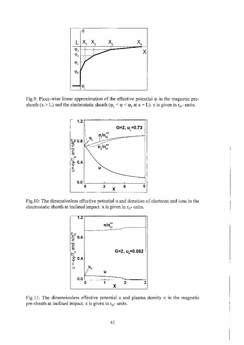
The hot ion magnetic pre-sheath is located at x > L outside of the cold plasma (see Fig. 3 ). The flux of hot ions is described by the distribution function (81 ). In order to obtain the criterion of applicability of the effective potential approximation for hot ions the change ofthe vortex electric field over the hot ion Larmor radius near the edge of the cold plasma (at x = L) is estimated. In accordance with Eqs. (80) and (83) the condition for this criterion is r11 i << 1. This is well satisfied for the parameters of Sec. 5.2. Thus the same effective potential <p can be used both for electrons and ions. To calculate the value of the adiabatic invariant I for the region of <p =1:- 0 the spatial behavior of the effective potential as shown in Fig. 9 is used. The aim is to calculate the value of <pL. For the analysis of the ion pre-sheath zero thickness of the sheath ( due to the fact that r 0 << r11) and linear approximations of the dependence of the potential at x > L in each cell of ion pre-sheath indexed with j= l..J are used. The index L will be used only for <pL. Hence the effective potential is approximated by:
with pj = t(<i>j -<pj-t)/(xj -xj-t), wj = <i>j-1 -2Pjxj-l' Xo = L, {j>J = 0
To describe the regions x < L (the cell with j = 0) and x :?: x1 (the cell with j = J+ 1) the definitions for pj and wj are extended to Wo= <i>L> Po= 0, WJ+I = 0, PJ+I = 0.
Attention has to be given to some consequences of the potential jump at x = L. Due to this break the conservation of I at the moment when the trajectory of an ion touches the sheath (i.e. after minimal position of ion oscillation motion xmin has approached to x = L: xmin :S L) is not valid because after this moment there occurs a significant change of the transversal projection during one cycle of transversal motion. The value of H _1_ should be constant at this cycle but the value of the adiabatic invariant gets some definite increment ~I (being calculated below). As a result it is taken I = I0 if the transversal projection is xmin >Land I= I0+M for xmin :S L, i.e. Eq. (81) in the (X,Z)frame is transformed to
(121)
with 8(s) = (0, s < 0; 1, s :?: 0) and xc<o> the leading center position corresponding to xmin=L. Considering the transversal projections of the trajectory at Z = 0, final results are valid for each Z due to symmetry. The projections are determined either by the parameter xmin or xmax which depend Oll XC. To shorten the expressions the following dimensionless variables (neglecting the difference between cosa and 1) are used:
W = -e<p /I 0 , W j = -e<p j /I 0 , W L = -e<p L /I 0 , W j = -e Wj /I 0 ,
Pj =-erhiP.i/Io ,s=(X-L)/rhi, i=I/10 , h = HJ../1 0
with jmin> jmax the indexes of the boundary cells of the trajectory projection location. It is valid 0 :S jmin :S jmax :S J+ 1. For the general expression for i is finally obtained:
30
with a · = (s. - s - p . )/~h + e · a'· = (s. 1 - s - p · )/~h + e. J J c J J ' J J- c .I .I '
with the designation f( x)j: = f(b)- f( a) and with smin and smax given as:
Sm in =Sc + P,~· ' - ~h + 0,~· ' ' Smax =Sc + P,~· + ~h + e I' mm mm max . max
The indexes jmin and jmax are determined from the condition that they bound the region -1 :S a:; < aj :S 1. They can easily be found numerically.
Simplest types of projections: 1. ( deeply in the hot pre-sheath)
Smax < 0 ; i = 1 + ~i ' jmin = jmax = 0 ' E) 0 = W L'
i = h + W L' Sm in = Sc - ~h + W L ' Smax = Sc + ~.-h-+_W_L
scCO) defined by s~o) = ( x~o) - L )/ri is obtained from the equation
at smin = 0. Substituting the result s~o) = ~h + w1 into Eq. (123) for j = jmin = 0 yields the following expression for ~i:
(124)
For small differences <pL- <p 0 it is obtained ~I oc ( <pL- <p 0 )2
. From Eqs. (74) and (121) after transformation to dimensionless variables it is
obtained:
8 27! 00
( ) oo cos 0 J J (· . ( (o) ))( . 2 )-I/2 nhi s = nhi -- d11 8 1 -1- ~18 Sc -Sc 1- h sm 80 dh
2n o o (125)
with 11 the angle of the perpendicular velocity polar coordinates v x =v 1_ cos11, vY =v 1_ sin11. When carrying out the integrating over h, 11 should be fixed. The relation between h and sc follows from the expression Py- micoiX = mivy:
sJh) = s + ~h + w{s) sin 11 (126)
31
The dependency under the integral in Eq. (125) on 11 is only irnplicitly via sin11 in sc of Eq. (126). Due to this if integrating over d11 frorn 0 to 27t the integration is repeated two tirnes. Hence it is sufficient to integrate over d11 frorn -7t/2 to 7t/2 (thus having only positive sign of cos11). Replacing the variable h by i and perforrning the internal integration it is obtained
n hi (s) = nhi 1t -1 cos8 0 J~~/2 (1- hsin2 8 0) -1/
2 ( di/ dh )-
1 d11 (127)
with h the solution ofthe equation
(128)
For the derivation di/dh it is obtained:
~ = _!_ ji (arcsin(a)J:~- sin 11 '(h + ej)/h + w(s)~la:) (129) dh 7t ·- · J V a.i J- lmin
In particular for the above rnentioned siruplest types of projections 1 and 2 it is obtained di/dh = 1, i.e. the relation of ion densities for both sides of the whole potential sheath:
The usual potential ~ in the ion pre-sheath is found frorn the quasineutrality equation:
(130)
The electric current of cold electrons cornpensates the current of the hot electrons. The current of hot ions is neglected. To calculate the potential in the sheath the Poisson equation for ~ has to be solved. Due to the fact that the vortex part of the electric field is srnooth at x = L the Poisson equation can be forrnally applied for the effective potential:
with designations "-co" and "+co" denoting the conditions at the conventional boundaries of the sheath which are assurned to be infinitely far because of the zero approxirnation for the srnall pararneter r0 /rhi·
The calculation for the ion pre-sheath, like that for the collisional region, needs as only external unknown pararneter uL = -ecpL/T". uL will be obtained after solution of the sheath problern (131 ). Frorn the condition of zero electron current jhe + jce = 0
according to Eqs. (20), (26) it is obtained n: = n~e e-"L /2~7tUL . Quasineutrality at
x~co: n~i = n~e + n: in accordance with Eqs. (19), (32), (52), (25) or (127) gives
n~c = qn~. After this Eq. (131) for the dirnensionless potential u(s) = -ecp/T" has the form:
32
with s=(X- L)/r0 , h and di/dh given by Eqs. (128) and (129). For solving the problern of the quasi neutral ion pre-sheath it is assumed on = 0. The following relation is valid between the dimensionless potentials u and w: u = Gw with G = IofTh.
In the narrow sheath it is allowed to neglect the explicit dependency in the left terrn of the RHS of Eq. (132) on s but the dependency of the ion density on u has to be kept. Therefore Eq. (132) can be integrated over s from s = -co to s = +oo with the weight function du/ds thus obtaining the equation for uL:
B ~ jB 0 = 4 0 (133)
The system of equations (130), (132), and (133) has been solved nurnerically. The results of this calculation for the pitch-angle 80=rc/4 and G=2 are presented in Figs. 10 and 11, showing the dependencies of the dirnensionless potential u(~), u( s) both for the sheath and for the ion pre-sheath as well as the densities of the ions and the electrons there. Results of calculations perforrned for different values of G are listed in Table 4.
It was also checked numerically that the Bohm criterion is valid for the points of the Table 4, but not for smaller values ofG. The main drop ofthe potential occurs in the sheath providing the values of <pL = -ThuL/e which cannot change the value of the parameter K significantly. Therefore the estimations in Sec. 5.2 for K = 7 are confirrned by the analysis of the current part.
The behavior of the effective potential is rather close to that one for perpendicular irnpact if the spatial coordinate is shortened by the factor sina with a the inclination angle. According to Fig. 11 the potential in the ion pre-sheath changes only slightly in contrast to the case of the traditional ion pre-sheath problern8
•10 where the
rnain potential drop occurs in the pre-sheath because the absorption of ions at the solid wall decreases their density significantly. For inclined irnpact ions cannot be absorbed irnrnediately by the cold plasrna because their stopping range A.hi is assurned tobe rnuch larger than their full path of immersion into the cold plasrna. Thus their density doesn't decrease significantly in the ion pre-sheath region. The Bohrn criterion is valid if GJ.. = Gsin11 > 1,75 with 11 the pitch angle of the rnono-energetic hot ions at x = oo. To fulfill this condition acceleration ofthe hot ions in the hot pre-sheath is required9
•
7. CONCLUSIONS
Potential profiles have been calculated for perpendicular and inclined impact of hot plasrna. In terrns of effective potential the results are identical. However there are important differences in the behavior of the electric potential of both cases as is schernatically indicated in Fig. 12. In case of perpendicular irnpact of hot plasrna the rnain electric potential drop occurs in the rather narrow hot electron collision stopping region (see curve 1 of Fig. 12). The electric field created by this potential drop
33
effectively stops the hot plasma electrons. Their energy deposition into the main volume of the plasma shield amounts only up to 10 %.
In case of inclined impact of the hot plasma an effective potential being the sum ofthe electric potential and a vortex term has tobe introduced (see curve 2 ofFig. 12). In the electric drift region the effective potential is zero thus the electric potential compensates the vortex term. The rather large electric potential drop gives rise to an electric field there which causes a drift of the hot plasma in lateral direction. The electric potential drop ~~ in the collisional region is proportional to a 2 and thus is rather small in comparison with the potential drop for perpendicular impact. Generally the increase of inclination of the confining magnetic field leads to a decrease of the role of the electric potential in the shielding layer and to an increase of the role of the vortex electric field for the stopping ofhot electrons.
In case of inclined impact of hot plasma an electric current is produced which leads to the generation of an additional magnetic field BY in the plasma shield. The increase of the magnetic pressure gradient caused by BY could result in a self compression of the edge of the plasma shield at times comparable or smaller than the characteristic disruption time. BY thus becomes a substantial feature of the expansion of the plasma shield. Therefore the dynamics of the cold plasma shield is influenced by the time evolution of BY. For evolution of the shielding efficiency of the plasma shield the self compression of the edge of the shielding layer by the magnetic field BY and the dynamics of the ExB drift of the hot plasma still have to be studied in detail.
The characteristic time of development of important effects predicted by the model is much less than the disruption time (the increase of magnetic pressure due to additional magnetic field component By up to the value of plasma pressure and lateral drift shift of the incoming hot plasma flux in the vicinity of cold plasma up to the value of the SOL thickness happens on time scales of 1 o-s s in accordance with the results of analysis carried out in Sec. 5.2 and shown in the Table 3 and in the last paragraph of the section). This circumstance gives additional argument for the use of tokamak parameters as input for the model. The model is valid as long as the additional magnetic field is less than the guiding magnetic field, for the corona this time is of the order of the disruption time 1 o-4 s. The small characteristic time leads to the conclusion that calculations of the hot plasma-target interaction resulting in the target erosion should take into account magnetic self-compression and lateral electric drifts.
7. ACKNOWLEDGEMENT The authors would like to thank Sergey Pestchanyi from TRINITI Troitsk for
fruitful discussions and participation at the initial stage of this work and Heide Hofmann from FZK Karlsruhe for her patience in typewriting the manuscript.
D.Toporkov, A.Zhitlukhin, J. Nucl. Mater. Vol. 220-222 (1995), 1066.
34
51. Landman, H. Würz, In 24th Conference on Controlled Fusion and Plasma Physics (European Physical Society, Berchtesgaden, 1997), Vol.21A, Part IV, p.1821.
6G.D.Hobbs, J.A.Wesson, Plasma Physics, Vol. 9 (1967), 85. 7P.C. Stangeby, In Physics of Plasma-Wall Interactions in Controlled Fusion edited by
D.E. Post and R. Behrisch (Plenum Press, New York, 1986), p. 41. 8R. Chodura, ibida p. 99. 9K.U. Riemann, J. Phys. D, Appl. Physics, Vol24 (1991), 493. 10D.D. Ryutov, Contrib. Plasma Phys. Vol 36, 2/3 (1996), 20. 11 L.L. Lengyel, V.A. Rozhansky, I.Yu. Veselova, Nucl. Fusion, Vol36 (1996), 1679. 12L.L. Lengyel, V.A. Rozhansky, I.Yu. Veselova, P.J. Lalousis, Nucl. Fusion, Vol 37
(1997), 1245. 13S.Pestchanyi, H. Würz, B.Bazylev, F.Kappler, I.Landman, In 24th Conference on
Controlled Fusion and Plasma Physics (European Physical Society, Berchtesgaden, 1997), Vol.21 A, Part III, p. 981.
14H. Würz, B.Bazylev, F.Kappler, I.Landman, S.Peschannyi, G.Piazza, Fusion Technology 1996, edited by C.Varandas and F.Sierra, Vol.l, p.191.
15The electrical stopping was approximately taken into account by assuming that ions and electrons contribute equally to the deposited energy. 16The collisional region consists of the main volume of the cold plasma shield and of the electrical pre-sheath. 17S.I.Braginskij. Transport phenomena in plasmas. In: 'The problems of plasma theory'
edited by M.A.Leontovitch, 'Atomizdat', Vol.l (1963), p.183 (in Russian). 18F.Hinton, In Basicplasma physics I, Editors A.A. Galeev, R.N.Sudan, North-Holland
Publishing Company, 1983. 19L.D.Landau, E.M.Lifshits. Mechanics. The course of theoretical physics, 'Nauka',
Vol. 1 (1973), (in Russian). 20D.E.Post (ed), ITER Physics, ITER Documentation Series, No.21, Chapter 4 (IAEA,
Vienna, 1990). 21 B.K. Suydem, TID/7558 Conf. on Controlled Thermonuclear, Fusion Washington, DC
Feb. 3/5, 1958. 22L.D.Landau, E.M.Lifshits. Hydrodynamics. The course of theoretical physics,
'Nauka', Vol. 6 (1986), (in Russian). 23H. Knöpfe!, Pulsed high magnetic fields, North Holland Publishing Company 1970. 24P.C.Stangeby, A.V.Chankin. Nuclear Fusion, Vol. 36 (1996), 839.
35
Table 1. The dependence of the sheath potential on the dimensionless
energy G of the incoming hot ions.
G 0.55 1 0.90 0.69 0.54 0.57
2 5 0.58 0.52 0.60 0.63
Table 2.Typical values of the dimensionless parameters
G= 1 y=1/70 z = 6 E = 1/10 q = 0.95 qe = 0.16 q; = 1.77
y = 0.076 u_"'=2.8 = 7.28
Qeo = 11% QeL = 81% Q;=8%
Table 3. Typical dynamics of the additional magnetic field
(for t0=0.03 s, ~-t=lOO, K=7, ß=O.Ol)
time [ s] 10·5 3 10·5 10·4
x= ~-tt/t0 0.04 0.12 0.4 f(x) 0.034 0.1 0.27 b
0 2 10·3 7 10·3 2 10·2
BY L/B0 0.08 0.3 0.8 qb 0.6 9 64
Table 4. Results of calculations for electrostatic sheath
G
and ion pre-sheath
1.75 0.79
0.095
2 0.73
0.082
3.5 0.57
0.043
36
Figures captions:
Fig. 1: Density distributions of the cold and hot plasma ions (nci• n11;) and electrons (nce• n110). X< 1: A110- units, x > 1: 10 r0 - units.
Fig. 2: Dimensionless potential and particle fluxes in the cold (x < 1) and hot (x > 1) plasmas. Uhe - hot electrons, jce - cold electrons, jhi - hot ions, j 11 / - reflected hot electrons). x < 1: A110- units, x > 1: 10 r0 - units.
Fig. 3: Schematic structure of the cold hot plasma interface (for descriptions of regions see Sec. 2.1)
Fig. 4: Coordinate transformation, non-compensated current -ej. in the plasma shield
and compensating current -el0 inside the structure. B0 guiding magnetic field, a -inclination angle, 1 thickness of the electric drift region.
Fig. 5: Schematic current distribution in the toroidal geometry at inclined impact of hot plasma onto cold plasma shield.
Fig. 6: Normalized energy deposition ofhot electrons at perpendicular impact Fig. 7: Camparisan of realistic y-component of magnetic field BY outside of the
shielding layer and that one used in the model. Fig. 8: ExB drift ofthe hot plasma and evolution ofthe shielding layer. Fig. 9: Piece-wise linear approximation ofthe effective potential <p in the magnetic pre
sheath (x > L) and the electrostatic sheath (<pL < <p < <p0 at x = L). x is given in the r1,;- uni ts.
Fig. 10: The dimensionless effective potential u and densities of electrons and ions in the electrostatic sheath at inclined impact. x is given in r0 - units.
Fig. 11: The dimensionless effective potential u and plasma density n in the magnetic pre-sheath at inclined impact. x is given in r11;- units.
Fig. 12: Schematic distribution of effective ( <p) and electric ( ~) potential at inclined impact. Symbols .6.<p and .6.~ show potential changes over the plasma shield. x<L: aA11e- units.
Fig.1: Density distribution of the cold and hot plasma ions (nci• n11;) and electrons (nce' n11e). X< 1: A11e- units, x > 1: 10 r0 - units.
1.5
~ t1.0 . II Jce ~ ------------~----~
0.5
1.5
Fig.2: Dimensionless potential and particle fluxes in the cold (x < 1) and hot (x > 1) plasmas. G11e- hot electrons, j 11;- hot ions, Y11e- reflected hot electrons). x < 1: A11e- units, x > 1 : 10 r 0 - units.
cold wall 'A sina. r0 - ce
t.. sina. rhi ! rhi E ·:-·-• f-' --++-• ,.;._.' :
'A sina. :--.i l -. h~--i-1 l l
1 l 3 i 4 i s i si l ; : l ~ X 2'
Fig.3: Schematic structure of the cold hot plasma interface.
38
z f Bo ,
I , , I
' I , z ! , , ,
I , I I
' , , , , I I I I , ' , ' ' ,
I I I I I I
I I I , ' ' ,
' , ' I
I I
' I
' , I
' ' , I ,
I I ,
I , ' , ,
' , I I
1 ..,__-+~x
D
Fig.4: Coordinate transformation, non-compensated current -eje in the plasma shield and compensating current -el0 inside the structure. B0 guiding magnetic field, a inclination angle, I thickness ofthe electric drift region.
x: pe'l'endlcular to target y: lateral (pell'. to plane) z: toroldal
bot corel electric drift region
colllslonless plasma
cold collisional plasma (plasma shield)
wall (divertor plate)
compensating current in inside structure
Fig.S: Schematic current distribution in the toroidal geometry at inclined impact of hot plasma onto cold plasma shield
39
12
>< 10 Normalization: ~ ~w 8 Qe(1) = 1 1:: 0
~ 6 0 c. ~ 4 >-E> Q) 2 1:: Q)
Fig.6: Normalized energy deposition of hat electrons at perpendicular impact. x is given in A11e- units.
, the model
' ' '\ ' ' J', real '\. behavior ,
....... ......
OL--------+------~----L D X
Fig. 7. Camparisan of realistic y-component of magnetic field BY outside of the shielding layer and that one used in the model
SOL
v =cExB~ ~ ~ d 82! ' E., • 80 • ' ' • I
' '
' I I
' I
vd I ' l I I
I I , I I I
I I
~ ---~------- ---~------- '-, /final
1( Initial ~
/- shield plasma shield
/ /·"" /. " /
d1vertor plate
total erosion width
Fig.8: ExB drift ofthe hat plasma and evolution ofthe shielding layer.
40
cp
X
Fig.9: Piece-wise linear approximation of the effective potential cp in the magnetic presheath (x > L) and the electrostatic sheath ( <pL < <p < cp0 at x = L ). x is given in r11i- units.
'0 c ro .c: ~ 04 o/ . II ;::,
0.0 L------'-------L ___ __J
0 3 X
6 9
Fig.l 0: The dimensionless effective potential u and densities of electrons and ions in the electrostatic sheath at inclined impact. x is given in r0 - units.
Fig.ll: The dimensionless effective potential u and plasma density n in the magnetic pre-sheath at inclined impact. x is given in r11 i- units.
41
0 plasma shield
A~ =~L- ~- 1iTh NP= cpL- cp - T h
Acp » M
L ele~trlc drill D t·egJOn
X
Fig.12: Schematic distribution of effective ( <p) and electric ( ~) potential at inclined impact. Symbols ~<p and ~~ show potential changes over the plasma shield. x < L: Ahe- units.