Implementation of a Disaster Resilient Linux Cluster with Storage Subsystem Based Data Replication Werner Fischer DIPLOMARBEIT eingereicht am Fachhochschul-Diplomstudiengang Computer- und Mediensicherheit in Hagenberg im Juni 2004
Transcript
Implementation of a Disaster ResilientLinux Cluster with Storage Subsystem
Hiermit erklare ich an Eides statt, dass ich die vorliegende Arbeit selbst-standig und ohne fremde Hilfe verfasst, andere als die angegebenen Quellenund Hilfsmittel nicht benutzt und die aus anderen Quellen entnommenenStellen als solche gekennzeichnet habe.
6 Problem Statement 296.1 What is it all about? . . . . . . . . . . . . . . . . . . . . . . . 296.2 Analysis of today’s Solutions . . . . . . . . . . . . . . . . . . 30
6.2.1 No Linux Support . . . . . . . . . . . . . . . . . . . . 306.2.2 Source Storage Devices at one Site only . . . . . . . . 306.2.3 Mandatory Quorum Devices at a third Site . . . . . . 30
6.3 What is the Benefit? . . . . . . . . . . . . . . . . . . . . . . . 30
This thesis is part of my studies for Computer and Media Security in Hagen-berg, Austria. It was written in co-operation with IBM Deutschland GmbH,Mainz.
I thank Alexander Warmuth, my tutor at IBM, for the great supportduring my internship and writing of my thesis. Also thanks to RobertKolmhofer, assessor at the University of Applied Sciences Hagenberg. Ithank all the colleagues working in the Advanced Technical Support at IBMMainz for the input, ideas, and discussion during coffee breaks. Their hintsmade me think about things again and again. Another big help was thesupport of the Tivoli System Automation Team from Boblingen. Thankyou Enrico and Thomas! Thanks also to Paul McWatt, who did anotherproof-read of the thesis.
Last, but not least, I want to thank my parents for the big supportthrough the four years of my studies.
viii
Kurzfassung
Hochverfugbare EDV Dienste gewinnen zunehmend an Bedeutung. Der ho-chste Grad an Verfugbarkeit kann durch Desaster-bestandige Cluster, dieuber zwei oder mehrere Rechenzentren aufgebaut sind, erreicht werden. Im-plementierungen von derartigen Architekturen gibt es fur einige kommerzi-elle UNIX Betriebssysteme sowie fur Mainframes. Losungen fur Linux fehlennach wie vor in diesem Gebiet.
Ein springender Punkt bei der Implementierung eines Desaster-bestandi-gen Clusters ist die Spiegelung oder Replizierung von Daten. Moderne Spei-chersysteme bieten eingebaute Hardwarefunktionen fur die Datenspiegelung.Diese haben einige Vorteile gegenuber Software-basierter Datenspiegelung.Hardware-basierte Spiegelung fuhrt im Gegensatz zur Software-basierten zukeiner erhohten Systemlast auf Cluster-Knoten. Ein weiterer Vorteil ist dieTransparenz von Hardware-basierter Spiegelung gegenuber Cluster-Knoten.Dies vereinfacht das Hinzufugen, Ersetzen oder Entfernen von Knoten.
In der Diplomarbeit werden einige allgemeine Bereiche von hochverfug-baren Computer-Systemen diskutiert. Zu Beginn wird ein Uberblick uberHochverfugbarkeitstechnologien fur lokale Cluster gegeben und einige Grund-lagen uber Disaster Recovery erklart. Weitere Themen sind Details uberMechanismen zur Datenreplizierung und der derzeitige Stand der Technikim Bereich Disaster Recovery. Die Problemdefinition beschreibt das Fehlenvon Linux-Losungen und die Einschrankungen von vorhandenen Losungenfur andere Betriebssysteme. Als mogliche Losung wird ein Prototyp fur dieAutomatisierung der Datenreplizierung durch Knoten eines Linux-Clustersprasentiert. Das Verhalten dieses Prototyps wird im Testkapitel erlautert.
ix
Abstract
Highly available IT services are becoming more and more important. Thehighest level of availability can be achieved with disaster resilient clustersspanned across two or more computer center sites. Implementations of thosearchitectures are available for a number of commercial UNIX operating sys-tems or mainframe systems. There is still a lack of Linux solutions in thisarea.
One key point of a successful disaster resilient cluster implementationis the mirroring or replication of data. Modern storage subsystems pro-vide built-in hardware functions for this data mirroring. They have someadvantages compared to software-based mirroring. Unlike software-basedmirroring, they do not add any processing load to cluster nodes. Anotherbenefit is that mirroring is transparent to nodes through the SAN (StorageArea Network). This makes adding, replacing or removing of nodes easilypossible.
The thesis discusses some general areas of high availability computing.It starts with a review of high availability technologies for local clusters andsome disaster recovery basics. The next topics detail data replication andthe current state of the art in disaster recovery solutions. The ProblemStatement describes the lack of Linux solutions and limitations of solutionsfor other operating systems. As a possible solution, a prototype for the au-tomation of data replication through Linux nodes is presented. The behaviorof this prototype in disaster situations is shown in the Tests chapter.
x
Chapter 1
Introduction
Today many businesses need their IT services continuously available. There-fore, High Availability (HA) Clusters are often used to prevent single pointsof failure in the data center. In the case of a complete site disaster, thesecluster solutions cannot help any more as they lack cluster nodes located ata different data center site.
Other solutions can integrate cluster nodes at different sites, they areknown as geographically dispersed clusters. These products often are normalHA cluster managers with small modifications. Many solutions use a soft-ware replication mechanism to keep a current copy of data at the second site(known as disaster recovery site). Software based replication mechanismshave some drawbacks, e.g. they cause an extra load on the hosts and haveto be maintained on all nodes of the cluster.
With the use of Storage Area Networks (SANs) in the computing envi-ronment, all data is stored on centralized storage subsystems. These sub-systems often provide hardware functions for data replication. As thesehardware based functions have been designed to work in disaster recoverysituations also without application cluster automation, they imply manualinterventions to accomplish a fail-over to the recovery site. Fully auto-mated solutions are only available for Mainframe computing environmentsand some commercial UNIX operating systems.
The goal of the diploma thesis is the integration of automated storagemirroring management functions with common Linux high availability clus-ter managers. The implementation is demonstrated in conjunction withIBM Tivoli System Automation for Linux (TSA)1 as cluster manager. TSAis only used as an example. The implementation itself is principally inde-pendent of the cluster manager used. With minor adaptations the prototypeshould also work with other UNIX operating systems.
The name Linux2 refers to the kernel originally developed by Linus Torvalds.Most people use the name Linux also for the GNU/Linux3 operating system.When talking about Linux, the complete GNU/Linux operating system ismeant through this thesis.
1.2 Why Linux?
Linux becomes more and more common, also in data center environments.One big advantage is the number of ports of Linux for different hardwarearchitectures. No other UNIX derivate supports more hardware architec-tures than Linux. With a broad usage of Linux in the company, systemadministrators can use their Linux knowledge on all the different hardwarearchitectures where Linux is used.
Linux is Open Source. Open Source Software has many advantages com-pared to commercial software. Without the power of Open Source SoftwareLinux would not be available for so many different hardware architectures.
Disaster resilient cluster solutions with storage subsystem based datareplication are partly available for other UNIX operating systems. Linuxhas been neglected in this area up to now.
As Linux (both the kernel and the whole distribution) is highly customiz-able, it can be cut down to provide only the functions that are really needed.This saves computing power and minimizes the risks of security flaws (themore software is running on a system, the higher is the probability of secu-rity flaws). Both characteristics (economical use of computing power and ahigh level of security) are significant for high availability clusters.
1.3 Why is it a worth-while question?
In a disaster situation automated processes will help to minimize downtimeand to prevent human errors. The white-paper IBM Storage Infrastructurefor Business Continuance [KP03] mentions ten lessons learned from 9/11.The most important point is “Successful recovery necessitates a greater de-pendency upon automation rather than people”. Crucial IT administratorsmay not be available in a disaster situation to execute critical tasks for asite fail-over. As a result, all necessary steps for a successful fail-over mustbe as simple as possible. This goal can only be achieved with a high level ofautomation.
Designing a disaster resilient cluster architecture is always a big challenge,independent of the operating system. Customer demands on those solutionsmay differ in many ways. This makes a common solution that fits most com-panies’ needs impossible. The thesis discusses the main challenges and givesan idea of how disaster resilient clusters can be implemented with storagesubsystem based data replication. The implemented prototype shows the in-tegration of automated storage management with high availability clusters.This prototype is not suited for production use without further investiga-tion and testing. As mentioned above, disaster resilient clusters must beindividually designed for every single implementation.
1.5 Structure of the Thesis
Chapter 1: Introduction
This introduction to the thesis.
Chapter 2: Review of HA Cluster Technologies
This chapter explains some basics of high availability clustering. As disasterresilient clusters are often implemented as geographically dispersed clus-ters, these principles are also valid for them. Differences between shared-everything and shared-nothing clusters are shown, as well as an overviewabout shared resource protection.
Chapter 3: Disaster Recovery Basics
Some concepts are discussed in this chapter. The Tier Levels of DisasterRecovery help to compare different solutions. Networking requirements nec-essary for disaster resilient configurations are explained. Finally, possibleconfigurations with two or three computer center sites are discussed.
Chapter 4: Data Replication
Data replication is a very important subject of disaster resilience. The re-quirements for data replication are explained. Also differences between sym-metric and asymmetric replication are explained. Replication mechanisms(synchronous, non-synchronous and asynchronous) are compared, replica-tion levels explained and some example implementations mentioned. Finallythere is a discussion about the question “Allow Data Writes if Mirroring isImpossible?”.
CHAPTER 1. INTRODUCTION 4
Chapter 5: State of the Art in Disaster Recovery
This chapter examines important disaster recovery solutions. The describedproducts include implementations for mainframes, commercial UNIX oper-ating systems and the OpenVMS operating system.
Chapter 6: Problem Statement
Describes the problem and evaluates today’s solutions presented in chapter5. It gives an outlook of the benefits of a Linux based solution.
Chapter 7: Implementation
This chapter focuses on the implementation of a prototype for automationof data replication management. The prototype is implemented as a BASH4
script.
Chapter 8: Tests
Different tests show the behavior of the prototype in certain disaster situa-tions.
Chapter 9: Conclusions
Final conclusions and some “lessons learned” can be found in this chapter.
4http://www.gnu.org/software/bash
Chapter 2
A Brief Review of HighAvailability ClusterTechnologies
2.1 Shared-Everything Cluster
In a shared-everything cluster, every cluster node can access shared resourceslike hard disks. To coordinate the access of all nodes, a lock manager isnecessary. If a node wants to use a shared resource, it queries the lockmanager and asks for access. When it does not use the resource any more,it sends a message to the lock manager so that it releases the access to thisresource. Lock managers are implemented either as a single lock manager(SLM), redundant lock manager (RLM) or distributed lock manager (DLM).
To allow parallel access to shared disks, a special file system must beused. For Linux OpenAFS1, OpenGFS2, Sistina GFS3 or IBM GPFS4 areavailable. They all use lock managers to coordinate access to the shareddisks.
2.2 Shared-Nothing Cluster
In a shared-nothing cluster, nodes only get exclusive access to a sharedresource. While one node owns a resource, no other node may access it inany way. A shared-everything cluster for example would allow concurrentread access to disk volumes. This is not possible in shared-nothing clusters.In the case of a fail-over or manual switch-over of services to another node,
the owning node must release the resource to allow access to it by anothernode.
In case of split-brain situations (where the cluster nodes are still alive,but cannot communicate with each other) there must be a guarantee thatno single resource is owned by two nodes at the same time. To prevent this,different quorum and resource fencing mechanisms are possible as shownlater.
2.3 Shared Resource Protection
2.3.1 Lock Managers
Lock managers are mandatory for shared-everything clusters. They can alsobe used for resource protection in shared-nothing clusters.
Single Lock Manager
If all locking information is stored only at a single server this server is referredto as single lock manager (SLM). As locking information is not available atanother server, the SLM is a single point of failure. It is not well suitedfor high availability clusters. For example, OmniLock from Sistina can beconfigured as a SLM.
Redundant Lock Manager
To improve this situation, the SLM can be configured in a sub-HA-cluster.This would be a simple two node shared-nothing cluster, which runs thelock manager. The locking functions need not be changed and the wholeimplementation can be the same as with a SLM. In such configurations, thelock manager is called redundant lock manager (RLM). An example againis OmniLock.
Distributed Lock Manager
Other lock protocols use a distributed lock manager (DLM). OpenGFS usessuch a DLM, called OpenDLM5. As an example the algorithm used in theOpenDLM implementation [Cah03] is described here. Knowledge about alock is distributed over three areas:
If a node wants to request a lock for a resource, it sends a query to theresponsible directory server for that resource. The information, which clus-ter node is the directory server for a special resource, is determined by afixed algorithm. Each node in the cluster acts as directory server for a rangeof resources. The directory server holds the information about whether aresource has ever been requested before and which node is the master serverfor the resource. If the resource has never been requested before, the in-quiring node will be the master server for this resource. In the other case,the inquiring node sends a message to the already defined master server.In the case that a node dies, the lock information of this node will be lost.The other nodes which accessed resources that were locked by that nodewill re-request the locks. This re-requesting works like requesting a resourcethat has never been requested before.
2.3.2 Quorum Mechanisms
Quorum mechanisms are only useful for shared-nothing clusters. They arenot suited for shared-everything clusters.
Quorum Disk
This mechanism uses a dedicated shared disk for storing quorum informa-tion. The disk must be accessible to all cluster nodes. As all nodes need bothwrite and read access to the shared disk, a special data structure that allowsconcurrent access has to be used. For example, this could be implementedin the following way:
Every node has its own area to write on the shared disk. Read accessis allowed to the whole disk. When a node wants to take over a resource,it must check if no other node owns the resource at that time. It sets alock indicator in its write-area. This prohibits other nodes from acquiringresources. Then the node writes the information that it owns the resourcefrom now on and releases the lock. If a node loses its connection to thequorum disk it must immediately release all shared resources as other nodeswill take them over. To make the detection of failed nodes possible, everynode must update a heartbeat information in its write area on a regularbasis. If the heartbeat information is out of date, the resource locks for thatnode are not valid any more.
Real Quorum of Servers (at least three Cluster Nodes)
Another possibility is to work with the real quorum count of cluster nodes.Therefore, at least three cluster nodes must be configured. Cluster nodesmay only use shared resources if they are part of the majority of clusternodes. If a single node cannot communicate with the other nodes anymore,
CHAPTER 2. REVIEW OF HA CLUSTER TECHNOLOGIES 8
it must immediately release all resources. In case of an even number of nodes,a tie-breaker must decide which sub-cluster should run the applications.
Tie-Breaker Mechanisms
Tie-Breakers can be used with two-node clusters or combined with real quo-rum when more than two nodes are used. If a node, that is running servicesin a two node cluster, fails (or half of the servers in a cluster with more thantwo nodes), the other node cannot be sure if the node really died or if onlythe communication with the other node failed. In the latter case, the nodethat seems to be broken may still use shared resources. Therefore survivingnodes must not start resources in a tie situation. Services that are alreadyrunning on surviving nodes will remain running. Before the other servicescan be brought up again, the tie situation must be resolved. The followingtie-breaker solutions allow this.
Manual Tie-Breaker With a manual tie-breaker configured, an operatormust decide which node may bring up shared resources. In case that halfof the nodes are not reachable anymore, one of the surviving nodes asksthe operator if it may bring up services. The operator enters a commandthat allows the node to bring up services only after he has verified that noassociated shared resource is in use by another node.
SCSI Tie-Breaker Shared storage is mandatory for this mechanism. Allcluster nodes need physical access to a shared SCSI disk. In case of atie situation the nodes try to get a SCSI Reservation of this shared SCSIdisk. Only nodes which can communicate with the node that got the SCSIReservation may use shared resources. All other nodes must immediatelyrelease all resources.
Quorum Server as Tie-Breaker Some shared-nothing cluster imple-mentations use so-called quorum servers for shared resource protection intie situations. Quorum servers work similarly to lock managers. The differ-ence is that they only grant exclusive access to shared resources. Quorumservers will only be queried in case of tie situations.
2.3.3 Fencing Mechanisms
Quorum mechanisms are software-level protocols which cannot assure inevery case that shared resources are not used simultaneously. The reasonis that quorum cannot guarantee the release of shared resources used byan unreachable node in a set period of time. If a node is stale and has noquorum anymore, it should release shared resources immediately. But thereare situations that can delay the release, as described in [Rob01].
CHAPTER 2. REVIEW OF HA CLUSTER TECHNOLOGIES 9
Fencing mechanisms try to quickly and reliably detach stale nodes fromshared resources. The difference to quorum mechanisms is the fact thatfencing mechanisms do the detachment without any cooperation of the un-reachable nodes.
Resource Fencing
Resource fencing uses hardware features of shared resources that guaranteethe exclusive use of the shared resource. For a shared SCSI disk, the SCSIreserve or SCSI persistent reserve attribute can assure this exclusive access.If the SCSI disk is a virtual LUN in a SAN, access rights can also be definedin the SAN switch or the storage subsystem itself. If the errant node tries toaccess the shared resource again, the access is denied through such hardwaremechanisms.
Resource fencing must be implemented for each type of resource sepa-rately. It requires support from the operating system for the implementedfencing type.
System Reset Fencing (STONITH)
STONITH (Shoot The Other Node In The Head) is another approach offencing. Errant nodes are reset and so forced to reboot. On startup, thenode tries to rejoin the cluster. Many problems that cause a node to fail canbe repaired through a reboot. If a node died completely, it cannot rebootanymore. It is always guaranteed that the errant node does not access anyshared resource. Other nodes can acquire shared resources without risk.
STONITH is often implemented via smart power switches or Intel’sIPMI6. A detailed description on STONITH can be found in [Rob01].
6Intelligent Platform Management Interface, see http://developer.intel.com/design/servers/ipmi
Chapter 3
Disaster Recovery Basics
3.1 Tier Levels of Disaster Recovery
Disaster Recovery can be implemented in different ways, depending on thebusiness needs and the available budget. The different ways can be consid-ered as the Seven Tiers of Disaster Recovery, as described in detail in [Wea04,p. 45]. The model was developed by the SHARE user group1 in 1992. Itcan be seen as a common model for disaster recovery solutions and makesit easier to compare different implementations.
Tier 0: No off-site data This first level represents “no disaster recoverypossibilities at all”. There is no data backup, no backup hardware or anykind of documentation on how to recover from a disaster. In case of adisaster, recovery usually will be impossible.
Tier 1: Data backup with no Hot Site Tier 1 represents “regulardata backups, which are stored off-site”. After a disaster, the copies on thebackup media are still available. All new data, which was created after thelast backup cycle will be lost. Before the data can be restored, new hardwaremust be installed.
Tier 2: Data Backup with a Hot Site This Tier is similar to Tier 1, asbackup media are stored off-site and will not be destroyed during a disasterat the production site. But at Tier 2 the backup is stored at a secondarysite with IT-infrastructure and facilities. Like Tier 1, all new data since thelast backup cycle will be lost in case of a disaster at the production site. AsIT-infrastructure is available at the secondary site, a shorter recovery timeis possible.
1SHARE is a non-profit, voluntary organization whose member organizations are usersof IBM information systems. It was founded in 1955. Details about SHARE can be foundat www.share.org.
10
CHAPTER 3. DISASTER RECOVERY BASICS 11
Tier 3: Electronic vaulting These solutions use techniques from Tier 2.Additionally, some data is electronically vaulted. This allows the creationof mission-critical data backups more often.
Tier 4: Point-in-time copies Tiers 1 and 2 deliver the backup data viathe PTAM (Pickup Truck Access Method) to the secondary site. Tier 4 alsoprovides point-in-time copies, but not tape based as the lower Tiers. Tier 4solutions are disk based and create the point-in-time copies via data links.These copies can be built more often, so less data will be lost in case of adisaster.
Tier 5: Transaction integrity These solutions are often database-driven,e.g. two-phase commit solutions. They provide consistency of data betweenthe production and the recovery site. Data loss will be little (often no dataloss at all). Tier 5 solutions can only be implemented at application level.
Tier 6: Zero or little data loss Disaster recovery at Tier 6 is realized viaapplication-independent replication mechanisms (e.g. storage sub-systembased data replication). Tier 6 solutions are used whenever no (or onlya minimum of) data loss is acceptable. They allow a rapid restore of ITservices.
Tier 7: Highly automated, business integrated solution As withTier 6, data copies at Tier 7 are maintained through application-independentreplication mechanisms. The difference is that Tier 7 solutions include a highlevel of automation, which minimizes the risk of operational errors in thecase of a disaster. The implementation of a prototype for a Tier 7 solutionfor Linux hosts is the content of this thesis.
3.2 Networking Requirements
To reduce the number of necessary site fail-overs it is wise to increase theavailability of the network infrastructure. The following technologies helpto reduce network outages.
3.2.1 Rapid Spanning Tree Protocol
The Rapid Spanning Tree Protocol (RSTP) is a standard of the Instituteof Electrical and Electronics Engineers, Inc. [Ins04]. It is the successor ofthe Spanning Tree Protocol (STP). The main advantage of the new RSTPis the reduced rebuild time compared to the STP.
RSTP supports, preserves and maintains the quality of the media accesscontrol in computer networks. It makes it possible to build redundant paths
CHAPTER 3. DISASTER RECOVERY BASICS 12
between network components. This increases the availability of the networkin case of single outages. RSTP fulfills the following requirements [Ins04, p.24]:
1. It eliminates data loops.
2. It provides highly available network communication by automatic re-configuration of the Spanning Tree topology in case of outages of LANcomponents.
3. During changes of the network topology (e.g. because of outages),the new active topology will stabilize within a short, known boundedinterval. This minimizes the time of network outages between anypair of end stations on the network. While typical STP networks needabout 30 to 60 seconds to bring the network up again, RSTP canachieve this within a few hundred milliseconds to about five seconds(depending on the vendor implementation).
4. The active topology is predictable and reproducible. It can be selectedthrough RSTP parameters.
5. RSTP is transparent for end stations on the network.
6. Communication between RSTP components needs only a very smallfraction of the total available bandwidth.
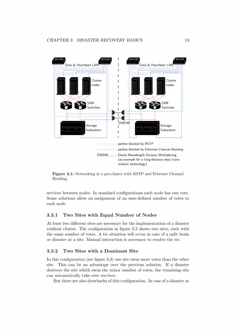
Because of the faster recovery time, it is wise to prefer RSTP to STP. Apossible setup with RSTP is shown in figure 3.1.
3.2.2 Ethernet Channel Bonding
Ethernet channel bonding2 for Linux enables network configurations withno single point of failure. Besides trunking and IEEE802.3ad Dynamic LinkAggregation, Ethernet channel bonding supports active-backup configura-tions for high availability configurations [Dav00]. With active-backup mode,nodes are connected to two switches. Only one of the two links is active ata time. In case of a outage of a switch, network cable or network card,the backup link will be activated. Nodes in figure 3.1 use Ethernet channelbonding.
3.3 Possible Configurations
All of today’s available disaster resilient cluster solutions use some kind ofquorum or lock manager for shared resource protection. Fencing mechanismsdo not seem to be suitable for geographical dispersed configurations. Bothquorum mechanisms and lock managers require a majority of votes to switch
2http://sourceforge.net/projects/bonding
CHAPTER 3. DISASTER RECOVERY BASICS 13
Figure 3.1: Networking in a geo-cluster with RSTP and Ethernet ChannelBonding.
services between nodes. In standard configurations each node has one vote.Some solutions allow an assignment of an user-defined number of votes toeach node.
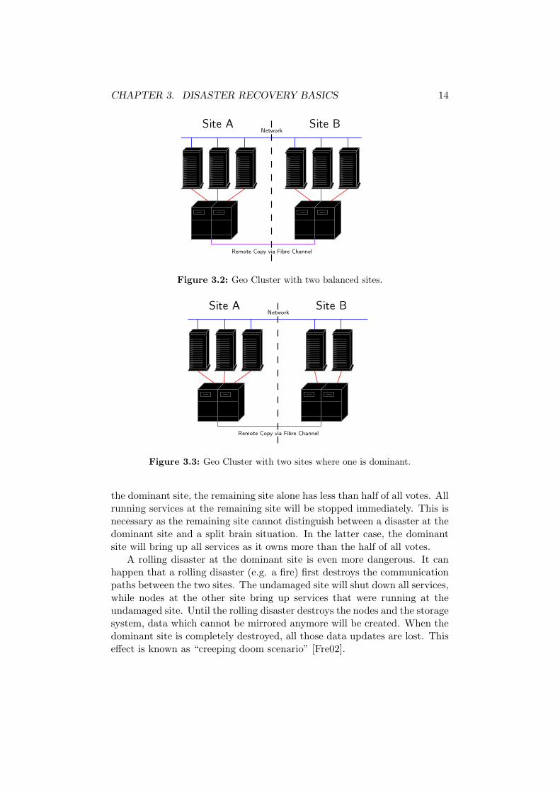
3.3.1 Two Sites with Equal Number of Nodes
At least two different sites are necessary for the implementation of a disasterresilient cluster. The configuration in figure 3.2 shows two sites, each withthe same number of votes. A tie situation will occur in case of a split brainor disaster at a site. Manual interaction is necessary to resolve the tie.
3.3.2 Two Sites with a Dominant Site
In this configuration (see figure 3.3) one site owns more votes than the othersite. This can be an advantage over the previous solution. If a disasterdestroys the site which owns the minor number of votes, the remaining sitecan automatically take over services.
But there are also drawbacks of this configuration. In case of a disaster at
CHAPTER 3. DISASTER RECOVERY BASICS 14
Figure 3.2: Geo Cluster with two balanced sites.
Figure 3.3: Geo Cluster with two sites where one is dominant.
the dominant site, the remaining site alone has less than half of all votes. Allrunning services at the remaining site will be stopped immediately. This isnecessary as the remaining site cannot distinguish between a disaster at thedominant site and a split brain situation. In the latter case, the dominantsite will bring up all services as it owns more than the half of all votes.
A rolling disaster at the dominant site is even more dangerous. It canhappen that a rolling disaster (e.g. a fire) first destroys the communicationpaths between the two sites. The undamaged site will shut down all services,while nodes at the other site bring up services that were running at theundamaged site. Until the rolling disaster destroys the nodes and the storagesystem, data which cannot be mirrored anymore will be created. When thedominant site is completely destroyed, all those data updates are lost. Thiseffect is known as “creeping doom scenario” [Fre02].
CHAPTER 3. DISASTER RECOVERY BASICS 15
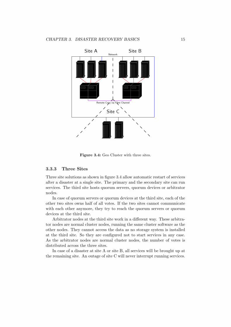
Figure 3.4: Geo Cluster with three sites.
3.3.3 Three Sites
Three site solutions as shown in figure 3.4 allow automatic restart of servicesafter a disaster at a single site. The primary and the secondary site can runservices. The third site hosts quorum servers, quorum devices or arbitratornodes.
In case of quorum servers or quorum devices at the third site, each of theother two sites owns half of all votes. If the two sites cannot communicatewith each other anymore, they try to reach the quorum servers or quorumdevices at the third site.
Arbitrator nodes at the third site work in a different way. These arbitra-tor nodes are normal cluster nodes, running the same cluster software as theother nodes. They cannot access the data as no storage system is installedat the third site. So they are configured not to start services in any case.As the arbitrator nodes are normal cluster nodes, the number of votes isdistributed across the three sites.
In case of a disaster at site A or site B, all services will be brought up atthe remaining site. An outage of site C will never interrupt running services.
Chapter 4
Data Replication
4.1 Requirements for Data Replication
Data replication is a key point in disaster resilient architectures. To preventdata loss, the following areas must be considered:
Data Consistency: preserves the write order of data records. This meansthat the data is immediately usable and recoverable. Inconsistent data onthe other side is not recoverable. Replication mechanisms that produceinconsistent data, like non-synchronous replication, must be combined withother technologies to provide usable point-in-time copies. Data consistencydoes not mean that the data is current.
Data Currency: indicates how up-to-date data at the recovery site is.The different data replication mechanisms achieve different levels of datacurrency.
4.2 Symmetric and Asymmetric Data Replication
Most of todays solutions, whether hardware- or software-based, provideasymmetric data replication. Data updates are written from one site tothe other, but not in both directions at the same time. Write access isonly possible at the primary site, where the source volume is located. Thetarget volume at the secondary site may only be accessible in read-onlymode. Before the volume at the secondary site can be mounted, the mirrorrelationship must be terminated or reversed.
Symmetric data replication can transfer updates from one site to theother in both directions at the same time. Therefore it allows write accessto both copies of the data. It requires a locking mechanism to prevent datacorruption.
16
CHAPTER 4. DATA REPLICATION 17
4.3 Data Replication Mechanisms
4.3.1 Synchronous Replication
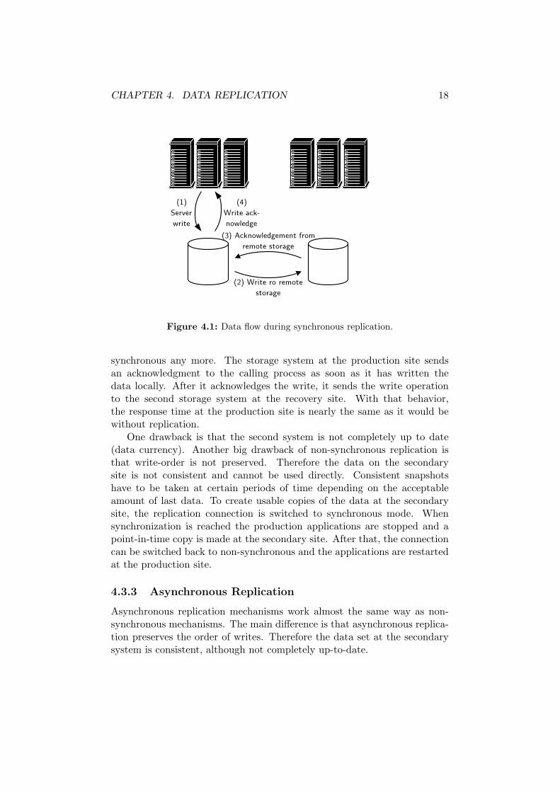
Synchronous replication mechanisms guarantee the same consistent datasetboth at the production and the recovery site as long as the links between thetwo sites are up and running. This guarantee is achieved as acknowledgmentsfor successful write operations are sent to the calling processes only after thewrite operation was also successful at the recovery site. Figure 4.1 detailsthe data flow:
1. A process writes data to the storage.
2. The storage subsystem (or some kind of software-based data replica-tion software, like a Logical Volume Manager or Software RAID) sendsthe write request to a second system at the recovery site.
3. The second system on the recovery site acknowledges the write oper-ation.
4. Now the local storage subsystem (or software-based replication soft-ware) sends the acknowledgment also to the calling process.
Although no single data record is lost in case of an outage of the primarystorage system, the use of synchronous replication also has limitations. Themain problem is the latency caused by waiting for the write acknowledg-ments. The signal propagation delay between the sites is the main determin-ing factor for this latency. Therefore, the distance between the productionand the recovery site is limited. Today’s synchronous replication mecha-nisms support up to 100 km. But those distances can influence the responsetime of applications noticeably. Extensive testing of the whole system isnecessary before going in production use.
There is one case where the logical order of data writes is not guaranteed.During an outage of the replication link the servers on the primary site maycontinue to write data to the primary storage system (depending on theimplementation). If data has been written at the primary site before thereplication link comes up again, all new and changed data will have to betransfered to the recovery site. The new and changed data tracks are notwritten to the recovery site in the same order as they have originally beenwritten to the primary storage system during the time of the outage. Duringthis resynchronization, the data at the recovery site will be be inconsistent.
4.3.2 Non-Synchronous Replication
If synchronous replication causes response times at the production site thatare too long, non-synchronous or asynchronous replication strategies canhelp. As the name implies, the data in the two storage systems is not
CHAPTER 4. DATA REPLICATION 18
Figure 4.1: Data flow during synchronous replication.
synchronous any more. The storage system at the production site sendsan acknowledgment to the calling process as soon as it has written thedata locally. After it acknowledges the write, it sends the write operationto the second storage system at the recovery site. With that behavior,the response time at the production site is nearly the same as it would bewithout replication.
One drawback is that the second system is not completely up to date(data currency). Another big drawback of non-synchronous replication isthat write-order is not preserved. Therefore the data on the secondarysite is not consistent and cannot be used directly. Consistent snapshotshave to be taken at certain periods of time depending on the acceptableamount of last data. To create usable copies of the data at the secondarysite, the replication connection is switched to synchronous mode. Whensynchronization is reached the production applications are stopped and apoint-in-time copy is made at the secondary site. After that, the connectioncan be switched back to non-synchronous and the applications are restartedat the production site.
4.3.3 Asynchronous Replication
Asynchronous replication mechanisms work almost the same way as non-synchronous mechanisms. The main difference is that asynchronous replica-tion preserves the order of writes. Therefore the data set at the secondarysystem is consistent, although not completely up-to-date.
CHAPTER 4. DATA REPLICATION 19
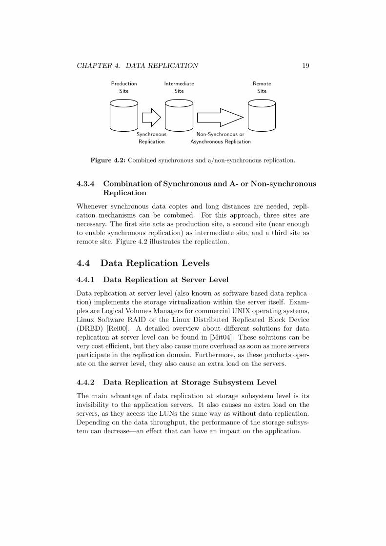
Figure 4.2: Combined synchronous and a/non-synchronous replication.
4.3.4 Combination of Synchronous and A- or Non-synchronousReplication
Whenever synchronous data copies and long distances are needed, repli-cation mechanisms can be combined. For this approach, three sites arenecessary. The first site acts as production site, a second site (near enoughto enable synchronous replication) as intermediate site, and a third site asremote site. Figure 4.2 illustrates the replication.
4.4 Data Replication Levels
4.4.1 Data Replication at Server Level
Data replication at server level (also known as software-based data replica-tion) implements the storage virtualization within the server itself. Exam-ples are Logical Volumes Managers for commercial UNIX operating systems,Linux Software RAID or the Linux Distributed Replicated Block Device(DRBD) [Rei00]. A detailed overview about different solutions for datareplication at server level can be found in [Mit04]. These solutions can bevery cost efficient, but they also cause more overhead as soon as more serversparticipate in the replication domain. Furthermore, as these products oper-ate on the server level, they also cause an extra load on the servers.
4.4.2 Data Replication at Storage Subsystem Level
The main advantage of data replication at storage subsystem level is itsinvisibility to the application servers. It also causes no extra load on theservers, as they access the LUNs the same way as without data replication.Depending on the data throughput, the performance of the storage subsys-tem can decrease—an effect that can have an impact on the application.
CHAPTER 4. DATA REPLICATION 20
4.4.3 Data Replication within the SAN
Sometimes, different storage subsystems from different vendors are locatedat the primary and secondary site. This is often the case after a merge oftwo companies, when the new firm uses one location as production site andthe other as recovery site. Replication approaches at storage subsystem levelonly work within products from the same manufacturer. With the use ofthe new virtualization engines, the data replication can be done at the SANlevel. This causes no extra load or maintenance on the servers and allowsthe connection of storage subsystems from different vendors.
4.5 Examples for Storage Subsystem Based DataReplication
4.5.1 IBM FAStT Remote Volume Mirroring
Remote Volume Mirroring (RVM) is a premium feature of the IBM FAStT1
storage system. It supports synchronous replication only. When a serversends a write request to the FAStT storage subsystem, the data will first belogged in a so-called repository drive. Then the controller writes the datato the primary logical drive, and also sends a remote write operation to thesecondary storage subsystem. After the data is stored on both the primaryand the secondary logical drive, the log record on the repository drive will bedeleted. Now the server gets an I/O completion indication from the primaryFAStT.
In case of a link failure, the servers at the primary site can still write tothe logical volumes. As the primary FAStT subsystem detects the link fail-ure (or outage of the secondary FAStT) it sends I/O completion indicationsback to the hosts as soon as the data is written to the local disks. There isno way to change this behavior.
The synchronization algorithm is not capable of partial resynchroniza-tions to start or resume the replication. After every link failure, a fullsynchronization of all mirrored volumes is performed. This can leave thedata at the secondary site in an inconsistent state for a long time.
4.5.2 IBM ESS Peer to Peer Remote Copy
Peer to Peer Remote Copy (PPRC) is the replication technology of IBM’sEnterprise Storage Server (ESS)2. There are different versions of PPRCavailable, depending on the ESS model and the version of the installedfirmware (licensed internal code—LIC). The following description accounts
for the latest version of PPRC at the time of writing, PPRCv2 with LIC2.3.
PPRC supports synchronous (PPRC-sync) and non-synchronous (PPRC-XD) replication. A combination of both is a available as Asynchronous Cas-cading PPRC (see section 4.3.4). For availability and performance reasons,multiple physical links can be used for PPRC connections. The behavior incase of a link failure is configurable. If write operations should be denied incase of a link failure, a feature called Consistency Groups (see section 4.6.2)can be enabled.
The synchronization algorithm is highly optimized. It is possible tosuspend a PPRC connection without the need of a full synchronization af-terwards. The secondary site can be updated later through the transmissionof only the data tracks that are out of sync. This behavior saves bandwidthand also is faster than a full synchronization. During the resynchronizationthe data of the target volume is not consistent.
The functions “PPRC Failover” and “PPRC Failback” allow the preser-vation of volume states, even in case of a disaster (as long as the ESS onthe production site is not destroyed). After the production site is availableagain, it is possible to transmit only the changed tracks back to the pro-duction site to have both sites synchronous again. Details can be foundin [Cea04, p. 417].
4.6 Allow Data Writes if Mirroring is Impossible?
Depending on customer needs, different strategies in case of a mirror linkoutage are possible.
4.6.1 Allow Data Writes without Mirroring
Some customers need the highest application uptime possible. If all mir-roring links (PPRC links) fail, services should continue to run. As a conse-quence, none of the new data will be mirrored to the other site. Therefore, arolling disaster which first destroys the PPRC links can be very dangerous.Clients located outside of all computer center sites can still use the highlyavailable applications and issue data writes. For example, these writes couldbe financial transactions, which cause money transferals to other banks. Thedebit entries are only written to one storage system. If the rolling disasterdestroys this storage system completely later on, the debit entries are lost.But the credit entries may have been transfered to other banks.
4.6.2 Deny Data Writes without Mirroring
Other customers insist on data mirroring whenever applications are running.They would rather stop services for a period of time, instead of allowing
CHAPTER 4. DATA REPLICATION 22
changes to the data. As a consequence applications must be shut down assoon as data mirroring is not possible anymore.
PPRC Consistency Groups
PPRC supports blocking of write operations in case of a complete PPRClink outage through the Consistency Group option [Cea04, p.74]. Withthis option set, SCSI or FCP (fibre channel protocol) attached open sys-tems receive a QUEUE FULL (QF) status byte code if write operationscannot be completed because of loss of PPRC links. The QF status indi-cates a full SCSI command queue. Data writes are not placed in the queue.Linux tries to insert the command in the SCSI mid-level queue through thescsi mlqueue insert() function [You97]:
Generic mid-level SCSI queueing: The point of this is that weneed to track when hosts are unable to accept a command be-cause they are busy. In addition, we track devices that cannotaccept a command because of a QUEUE FULL condition. Inboth of these cases, we enter the command in the queue. Atsome later point, we attempt to remove commands from thequeue and retry them.
The duration of a QF state can be configured in the ESS. The defaultvalue for the Consistency Group Time Out is set to two minutes.
Reactions on Queue Full
In case of a QF state, applications may behave in different ways. Some maycontinue to run, others may freeze or cause other unexpected behavior. De-pending on the monitoring implementation of the cluster manager, storageor applications will be detected as failed. This causes the cluster managerto fail-over applications. As the applications cannot be started on nodes atthe same site, a site fail-over is executed. The volumes at the recovery sitewill become PPRC sources in suspended state. Applications start at therecovery site, but data writes will not be mirrored.
To prevent this behavior, the cluster manager must be instructed to stopthe applications. This is the only secure way to prevent data writes in caseof a failure of all PPRC links.
A possible Solution with ESS SNMP Traps
The ESS can be instructed to send SNMP traps if a copy pair in a consistencygroup becomes suspended and the source volume enters QF. Multiple trapreceivers are supported. An enterprise management station should be one ofthe trap receivers. This ensures notification of system administrators in caseof critical situations. Other receivers are snmptrap-daemons running on the
CHAPTER 4. DATA REPLICATION 23
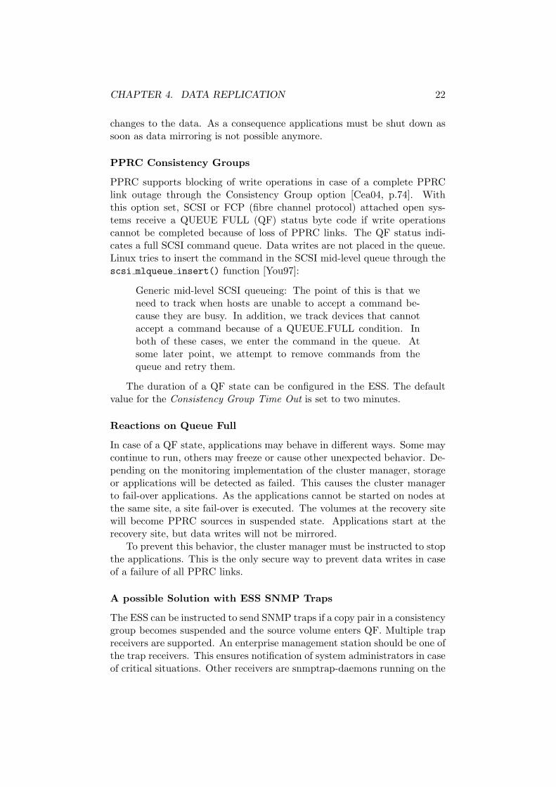
Figure 4.3: Handling of SNMP traps in a split-brain situation.
cluster nodes, one at each site. The two snmptrap-daemons are configuredas high availability services within the cluster. The daemon responsible forsite A may only run on nodes located at this site. The same applies for thedaemon at site B. The two daemons are necessary to guarantee the rightbehavior even in case of a split-brain situation. It must be possible for eachsite to separately shut down all services cleanly.
An example for an automated shutdown of applications is shown in figure4.3:
1. A split brain situation breaks all PPRC and network links.
2. Nodes receive a QF state on write requests.
3. ESS’ at both sites send SNMP traps to the trap receivers.
4. Trap receivers execute stop commands for the applications.
Unfortunately SNMP traps do not have guaranteed delivery. If the LANconnection to an ESS is broken, SNMP traps cannot be sent to the trapreceivers. It is possible to monitor the sending of SNMP traps throughtest traps. The sending of those test traps can be caused by cluster nodesthrough special command line interface commands (esscli create snmp).If these test traps cannot be received by the trap receivers, applications mustbe stopped. This is necessary as broken PPRC links traps would not bereceived. Although this may help in most situations, it is still theoreticallypossible that test traps are delivered correctly while other urgent traps arelost. As a consequence, mission critical applications that absolutely must notrun if mirroring is impossible, should not be automated with a graphicallydispersed cluster.
Chapter 5
State of the Art in DisasterRecovery
The following products and service offerings are examples for Tier 6 and Tier7 disaster recovery solutions. They are either available for IBM z/OS, IBMAIX or HP UX and are described to give an overview of the possibilities inautomated disaster recovery.
5.1 IBM GDPS for zSeries
GDPS (Geographically Dispersed Parallel Sysplex) is a service offering fromIBM that implements a Tier 7 solution for IBM’s z-Series mainframes1.There are different versions of GDPS. All of them use hardware-based datareplication. Details about GDPS can be found in [Kea04, p. 333] and[Wea04, p. 274].
5.1.1 GDPS/PPRC
GDPS/PPRC uses synchronous PPRC and allows applications to run atboth sites at the same time. However, all applications (whether they run atthe primary or secondary site) will read from and write to the disk systemat the primary site. This can lead to longer response times for applicationsrunning at the secondary site. An application running at the secondary sitewrites data to the primary disk subsystem. Then, the data must be mir-rored back to the secondary site. After the primary disk subsystem gets theinformation that the data has been mirrored, it sends the acknowledgmentback to the application.
Logical Units (virtual disks) for open systems (Unix, Microsoft Windows,Linux, Novell Netware and so on) can be integrated into GDPS/PPRC. This
1http://www.ibm.com/servers/eserver/zseries
24
CHAPTER 5. STATE OF THE ART IN DISASTER RECOVERY 25
function—Open LUN management—has been implemented because depen-dencies between mainframe and open system applications became more andmore frequent. GDPS/PPRC only integrates the data replication automa-tion for open systems. It does not automate the restart of open systemapplications.
5.1.2 GDPS/XRC
GDPS/XRC is an asynchronous disaster recovery solution and is based onExtended Remote Copy (XRC). XRC is a combined hardware and softwareremote copy implementation. It uses time stamps to preserve the orderof write operations. As the data replication between the primary and sec-ondary site is asynchronous, the data at the secondary site will always beslightly behind the data at the primary site. As a benefit XRC provides datareplication without any distance limits and only little application latency.As XRC manages the data consistency itself, GDPS must only provide theautomation of the recovery process. More details about XRC can be foundin [Kea04].
5.2 IBM eRCMF
Enterprise Remote Copy Management Facility (eRCMF) also is a serviceoffering from IBM. It can be implemented as a Tier 4 or Tier 6 solution foropen system disaster recovery [Wea04, p. 286]. eRCMF is well suited forvery large amounts of data, as it can preserve data consistency across mul-tiple Enterprise Storage Servers. eRCMF uses productivity center machines(PCMs), running on dedicated AIX servers.
eRCMF does not automate the restarting of servers and applications. Itmakes data volumes directly available at the secondary site after a disasterat the primary site. There is no need to bring up volumes and to start repli-cation fail-over tasks manually. When using synchronous PPRC, eRCMFworks as a Tier 6 disaster recovery solution. eRCMF also supports PPRC-XD (non-synchronous data replication) as a Tier 4 solution. The creationof the necessary point-in-time copies can be automated with eRCMF.
5.3 IBM HACMP/XD
HACMP is a high availability clustering solution for local clusters runningAIX operating systems. The optional package HACMP/XD also allows fail-over of services to nodes running at a different site. HACMP/XD can beimplemented with synchronous PPRC for distances up to 103 km betweenthe sites or with IP based mirroring for unlimited distance support. De-tailed information about HACMP/XD can be found in [Wea04, p. 296]
CHAPTER 5. STATE OF THE ART IN DISASTER RECOVERY 26
and [Int03a].HACMP/XD with PPRC automates the PPRC management. There is
no need to start fail-over replication tasks manually in case of a disaster. Thenodes of the HACMP cluster must have network access to the EnterpriseStorage Servers to execute preconfigured tasks when a fail-over or fail-backis necessary.
HACMP/XD with IP based data mirroring can be configured as a syn-chronous or an asynchronous replication solution. This makes unlimiteddistance support for asynchronous configurations possible. IP based datamirroring uses Geographic Mirror Devices (GMDs). The same software isused in the Geographic Remote Mirror for AIX (GeoRM), which can beused itself as a Tier 6 disaster recovery tool.
Note that HACMP is only available for the AIX operating systems.
5.4 HP-UX Disaster Tolerance Clusters
All HP-UX disaster recovery cluster products use HP MC/ServiceGuardcluster technology, which is a high availability solution for local clusters.Details about the HP technologies described below can be found in [Hew04],[Hew03], [BK03] and [Fre02]. Note that although the local cluster Service-Guard product is available for Linux, at the time of this writing the describeddisaster tolerant solutions are only available for HP-UX.
5.4.1 HP Extended Distance Clusters
Extended Distance Clusters (also known as Extended Campus Clusters, for-merly Campus Clusters) are MC/ServiceGuard clusters that are spannedacross different data centers separated by a maximum of 100 km. Each sitemust have an equal number of cluster members. Data is replicated via HP’sMirrordisk/UX, a server-based data replication software. Arbitration canbe done by dual lock disks for clusters of up to four nodes. A split-brain willoccur in this configuration, if both the heartbeat and the disk link betweenthe two sites fail. In this case both sites will bring up services, compromis-ing data integrity. Clusters with more than four nodes require a quorumserver or arbitrator nodes at a third location. Those configurations will notcompromise data integrity, even if the primary and secondary site cannotcommunicate via heartbeat and disk links.
5.4.2 HP Metropolitan Cluster
Metropolitan Clusters use storage subsystem based data replication for datamirroring. Both HP’s Continuous Access XP for XP arrays and EMC’sSRDF for Symmetrix storage systems can be used. Arbitrator nodes or a
CHAPTER 5. STATE OF THE ART IN DISASTER RECOVERY 27
quorum server at a third location are mandatory for Metropolitan Clusters.No kind of lock disks are supported with this cluster.
5.4.3 HP Continental Cluster
A Continental Cluster consists of two distinct MC/ServiceGuard clusterslocated at different computer center sites. Each of the two clusters maintainsits own quorum. As there is no support for automated fail-over, a thirdsite for arbitration is not necessary. The fail-over is initiated by a humanoperator.
Continental Clusters work with any data replication mechanism. Pre-integrated solutions for HP’s Continuous Access XP and EMC’s SRDF areavailable.
5.5 Sun Cluster 3.x
Automated disaster recovery for Sun Solaris can be implemented with theSun Cluster 3.12 software. This application-fail-over function is fully inte-grated with the operating system. Sun Cluster supports a cluster file system,which allows shared write access to volumes from multiple hosts. A maxi-mum of three nodes can participate in a campus cluster configuration, butonly two nodes can be used for running applications. The third node canonly be an arbitrator node. Both two and three-site configurations are possi-ble. Only the three-site setup guarantees system availability after a disasterat one site. In two-site clusters a quorum device is placed within one of thetwo sites. If that site fails, the other surviving node is useless as it cannotbring up services without manual interaction. Sun itself states that “expe-rience has shown that this technique is very error prone and requires highlyskilled personnel to implement correctly” [Str02, p. 15]. Thereby a two siteconfiguration does not seem to be suited for a disaster tolerant solution atall.
Sun Cluster supports both server and storage subsystem based data repli-cation. For storage subsystem based data replication, Hitachi’s TrueCopyis used. In case of an outage of a complete site, many manual steps will benecessary if storage-based data replication is used. This can even includeactions that must be taken by a Sun service provider [Sun04, p. 69].
Administration of the Sun Cluster does not seem to be easy, as Sunoften points out that well-trained, dedicated people must administer theinfrastructure, for example in [Str02, p. 4]. This can be very unfavorable asthese professionals may not be available in case of a disaster.
As Sun Cluster supports only two nodes that can run services, no highavailability can be implemented within a site. Every failure of a single
2http://www.sun.com/software/cluster
CHAPTER 5. STATE OF THE ART IN DISASTER RECOVERY 28
component leads to a site fail-over.
5.6 OpenVMS Cluster
OpenVMS3 is a shared everything cluster that uses a built-in distributedlock manager. With a maximum of 96 nodes in a cluster, all servers canwrite simultaneously to the same files of the cluster file system. The diskvolumes can be directly attached to all nodes or other nodes can serve thevolumes to the rest of the cluster.
Server-based data mirroring is supported through the Volume Shadow-ing product, a software-based RAID 1 solution. All write operations aresynchronous. Multiple disk drives can participate in this mirroring, theyare part of a so-called “shadow set”.
A single OpenVMS cluster can be spanned across two geographicallyseparated data centers. The applications may run at both sites at the sametime, as all data will be mirrored symmetrically and synchronously acrossthe different data centers.
OpenVMS uses a quorum strategy for arbitration. Therefore every clus-ter node gets a number of votes. In a split brain situation (in OpenVMScalled “partitioned cluster”), no group of cluster nodes would continue tooperate if both sites have the same number of votes. A group of clusternodes needs at least one more vote than half of the sum of all votes in thewhole cluster. It is recommended to configure three sites, where the nodesat the third site can act as tie breakers.
3http://h71000.www7.hp.com
Chapter 6
Problem Statement
6.1 What is it all about?
Local high availability clustering solutions for Linux have been available forquite some time. However, a fully integrated solution which is capable ofhandling hardware-replicated storage devices does not exist yet.
In case of a disaster many steps must be performed manually before theIT services can be brought up again at the recovery site. These steps canbe very error-prone if the administrator has no in-depth knowledge aboutthe storage subsystem, its replication mechanisms and the behavior andinternal operations of the cluster manager. Even the best trained personnelis no guarantee for the right sequence of actions, as a disaster is always adramatic situation that makes it very difficult to work. Nobody can assurethat these people will be available at the recovery site, as they may not havea chance to reach their workplace or have to deal with personal challengesafter the disaster. The most extensive solutions are not worth their effortif they rely on experienced administrators who may not be available at therecovery site.
To improve this situation, a higher level of automation must be achieved.All cluster nodes of the geographical dispersed cluster need the ability toconfigure the storage subsystem for fail-over and fail-back procedures. As thedata replication mechanisms of sophisticated storage subsystems are rathercomplex and support various states of operations, this problem cannot besolved easily.
There are some rules that must be fulfilled in a highly automated envi-ronment:
1. Data consistency must not be violated under any conditions.
2. Every single cluster node must be able to execute all necessary fail-overand fail-back operations.
3. In case of inconsistent replication states of the affected volumes, the
29
CHAPTER 6. PROBLEM STATEMENT 30
cluster manager must recognize this and stop all automated proceduresuntil human intervention.
6.2 Analysis of today’s Solutions
6.2.1 No Linux Support
Today there is no automation software for Linux available to handle hardware-based data replication. The solutions presented in chapter 5 are only avail-able for IBM’s z-Series mainframes, HP’s OpenVMS and some commercialUNIX operation systems like IBM AIX, HP UX and Sun Solaris.
6.2.2 Source Storage Devices at one Site only
IBM’s GDPS for z-Series allows data access only at the primary site’s storagesubsystem. Although applications may also run at the secondary site, thisdesign can have some performance implications, as described in section 5.1.1.
6.2.3 Mandatory Quorum Devices at a third Site
HP’s geographical dispersed cluster products, HP Extended Distance Clus-ter and HP Metropolitan Cluster, require quorum devices at a third site.HP Continental Cluster on the other side has no support for a third site.
6.3 What is the Benefit?
The implemented prototype enables Linux cluster products to integrate stor-age subsystem based data replication. This allows the design of disasterresilient Linux cluster configurations.
The prototype supports both two- and three-site configurations. Two-site configurations require the same number of nodes at each site. In case ofa site disaster or communication loss between the two sites, manual quorumassignment is necessary. A three-site configuration does not need such man-ual quorum assignments. Although only two sites can be used for runningservices, cluster nodes at the third site also have votes for quorum. Aftera complete site disaster, the remaining two sites have enough votes to getquorum. This allows the automatic recovery of services.
Another advantage is the possibility of active-active configurations. Au-tomation of storage replication can be individually configured for each appli-cation. Some applications may run at the primary site, while others run atthe secondary site. This allows a better utilization of computing resources.
Chapter 7
Implementation
7.1 Implementation Overview and Requirements
Every Linux cluster manager uses some kind of resources to manage highlyavailable services. E.g. a highly available NFS service consists typically of amount-resource, an IP-address-resource and the NFS-resource (NFS serverapplication) itself, which are started in this order during startup of the NFSservice. The resources can be used like init-scripts with at least a start, astop and a status parameter.
The implemented prototype provides a storage-resource for Linux clustermanagers. This resource can be used as first resource during startup of aservice before the mount-resource mounts the file systems. If the storage-resource can be started successfully, the data replication states allow mount-ing of the corresponding file systems. More details about the start processwill be shown in section 7.7.1.
The implementation uses IBM’s PPRC (Peer to Peer Remote Copy) ofthe ESS (Enterprise Storage Server). PPRC was chosen because it supportsthe following sophisticated data replication functions:
• Quick re-synchronization after outages of the replication links.
• Fibre channel links can be used full duplex for concurrent replicationin both directions.
• Automation of replication function via command line interfaces.
The storage-resource prototype must fulfill the following requirements:
• It must preserve data consistency.
• If the current data replication states do not allow data access, allnecessary actions to reach a state which may allow data access mustbe executed automatically.
31
CHAPTER 7. IMPLEMENTATION 32
• If the current states do not allow data access and there is no chanceof automatic actions reaching a better state, a detailed error log mustbe provided.
7.2 Cluster Manager Requirements
There are some requirements that a high availability cluster manager forLinux must fulfill before it can used with this implementation. At the timeof this writing, only Tivoli System Automation for Linux fulfilled these re-quirements. Therefore it was used as example cluster manager for the testscenario used in chapter 8. The following three requirements must be ful-filled.
7.2.1 Support for more than two nodes
For a disaster resilient configuration it is advantageous when at least threenodes participate in the geographically dispersed cluster. Cluster managerswith a maximum of two nodes per cluster do not allow local clustering ata site. With one node at each of both sites the maximum node count isreached. In case of an outage of a single node a complete site fail-overwill be necessary. Cluster managers that support more than two nodes willbe able to do a local fail-over in such a situation. This has the followingadvantages:
• The mirror relationship between the two sites does not need to bereconfigured. As a result, a local fail-over is faster than a fail-over tothe other site.
• Reconnecting clients to the other site takes more time as routing orDNS information must be updated before clients can reconnect.
• With most storage systems, a site fail-over causes the mirror relation-ship to be suspended. Data writes at the recovery site are not mirroredback to the production site without human interaction.
• A site fail-over causes more automated actions than a local fail-overdoes. There is a potential higher risk of failures.
7.2.2 No mandatory quorum device
To make both two- and three-site configurations possible, the cluster man-ager must not depend on a mandatory quorum disk or quorum server. Fortwo-site configurations, a manual assignment of quorum must be possible.
CHAPTER 7. IMPLEMENTATION 33
7.2.3 No mandatory fencing mechanisms
Fencing mechanisms cannot be used with disaster resilient clusters. Bothresource fencing and system reset fencing need hardware to support thefencing. If the fencing hardware is destroyed during a disaster at a singlesite, nodes at the remaining site cannot fence the destroyed components.
7.3 Storage Automation via Command Line Inter-face
Command Line Interfaces (CLIs) allow the automation of storage systemfunctions. Two different CLIs are available for the Enterprise Storage Server:the Storage Management CLI and the Copy Services CLI. Both are writ-ten in JAVA and communicate with the ESS via network connections. Allcommunication is encrypted. In-band communication via fibre channel con-nections is not supported. If the ESS is not reachable via the network,no ESS commands can be executed via the CLIs. The use of the CLIs isdescribed in detail in [Int03b].
7.4 Features of the Implementation
The written prototype automates nearly the complete PPRC managementvia the two CLIs. Only PPRC tasks must be created manually via the ESSSpecialist Web interface. Every application can be configured individually,as shown in section 7.6. This allows site A to act as production site for thefirst application and as recovery site for the second. Site B on the other sideis the production site for the second application and recovery site for thefirst. The terms “production site” and “recovery site” are used to explain theconcepts of the prototype in connection with PPRC terms. The prototypeitself does not care about production and recovery sites.
7.5 PPRC
7.5.1 PPRC Basics
PPRC Paths
PPRC uses so-called PPRC paths to replicate data to another ESS. PPRCpaths can be established between two Logical Sub-Systems (LSSes). AnESS consists of 16 LSS, which contain RAID-protected data storage on harddisks. Details about LSSes can be found in [Cea02, p. 68]. PPRC pathscan use multiple physical fibre channel links. This enhances the possiblethroughput and eliminates single points of failure in the replication stream.
CHAPTER 7. IMPLEMENTATION 34
PPRC Connections and PPRC States
PPRC connections are configured at volume level. To establish a PPRCconnection between two volumes, a PPRC path between the correspond-ing LSSes must exist. PPRC connections can be synchronous or non-synchronous. Every PPRC connection needs two volumes, one acting asPPRC source and one acting as PPRC target. If a volume is not part of aPPRC connection, it is referred to as PPRC simplex.
A PPRC volume can have one of the following states:
• full-copy
• suspended
• copy-pending
• none
• unknown
PPRC Tasks
Every PPRC action can be executed manually via the ESS Specialist WebInterface. To enable the execution of PPRC actions via command line in-terfaces, PPRC actions can be stored as PPRC tasks. The following PPRCtask types are possible:
• Establish paths
• Remove paths
• Establish Synchronous PPRC copy pair
• Establish PPRC Extended Distance copy pair
• Suspend PPRC copy pair
• Terminate PPRC copy pair
Depending on the PPRC task type, different PPRC paths or PPRC copyoptions are available. Details can be found in [Cea04, p. 232].
7.5.2 Establishing PPRC Paths
The implementation focuses on fibre channel links for PPRC paths. Al-though ESCON links may also work, they have not been tested with thisimplementation.
It is recommended to use at least two different physical links for PPRC.With fibre channel, each physical link can be used in both directions. Thisis not possible with ESCON.
Depending on customer needs, the PPRC consistency group option canbe activated during establishment of PPRC paths. This affects the behavior
CHAPTER 7. IMPLEMENTATION 35
in case of an outage of all PPRC paths between two Logical Sub-Systems(see section 4.6.2).
7.5.3 Necessary PPRC Tasks
Various PPRC tasks are necessary for each highly available service. In casea service uses more than one volume, the tasks must be configured for everyvolume and then combined into a group task. Tasks can only be created viathe ESS Copy Services Web User Interface. It is not possible to automatethe creation of PPRC tasks. Mandatory PPRC tasks are described in theparagraphs below:
PPRC Failover from Site A to Site B
During normal operations, volumes at the production site are in PPRCsource, full-copy state. Volumes at the recovery site are in PPRC target,full-copy state. The PPRC failover task from site A to site B is necessary ifthe application currently uses site A as production site and the applicationmust be switched to site B.
Nodes at site B cannot write to the PPRC target volumes. To allow writeaccess, a PPRC failover task must be executed successfully. This brings thevolumes at the recovery site (site B in this case) to PPRC source, suspendedstate. Volumes at the production site remain in their state. Nodes at therecovery site can mount the volumes in read/write mode. Updates to thesevolumes are not mirrored back to the production site. They are only markedto allow a fast resynchronization later with a PPRC failback task. Moreinformation on creating PPRC failover tasks can be found in [Cea04, p. 413and p. 426].
PPRC Failback after PPRC Failover from Site A to Site B
No data writes are mirrored to site A after the PPRC failover to site B. If thecurrent data at site B is valid, the mirroring to site A can be initiated witha PPRC failback task. The PPRC failback task does not allow a fail-backof the application to site A. It only ensures that volume mirroring is doneback to the former production site. To do a fail-back of the application,another PPRC failover task from site B to site A is necessary after thisPPRC failback task.
Before a PPRC failback task is executed it is a good idea to createpoint-in-time copies of the volumes at site A. If the new data at site B waserroneous, these copies can help as last known-good data sets. Withoutpoint-in-time copies, the PPRC failback overwrites these last known-gooddata sets. Until the PPRC failback task finishes, the volumes at site A haveno data consistency at volume level. There is only one usable copy of eachvolume during PPRC failback.
CHAPTER 7. IMPLEMENTATION 36
PPRC Failover from Site B to Site A
This is the same task as “PPRC failover from site A to site B”, but withswitched roles. The task is used for applications that use site B as productionsite and need to be switched to site A. It is also necessary for applicationsthat use site A as production site, to allow an application fail-back after awhole application fail-over (this includes a PPRC failover and PPRC failbackoperation).
The execution of this task will switch volume states at site A from PPRCtarget, full copy or suspended to PPRC source, suspended. Volumes statesat site B will remain the same. Again, no data mirroring takes place afterthis PPRC failover task.
PPRC Failback after PPRC Failover from Site B to Site A
This task is necessary to initiate data mirroring from site A to site B afterthe PPRC failover from site B to site A. Again, it is wise to make a point-in-time copy at site B in this case.
Establish PPRC Connections
To initiate the PPRC mirroring between volumes, this task for establishingof PPRC connections is necessary. PPRC connections can either be config-ured from site A to site B or from site B to site A, depending where thePPRC source volumes should be located initially. The necessary task typeis Establish Synchronous PPRC copy pair. The options Copy entire volumeand Permit read from secondary must be set. The latter option is necessaryto allow nodes at the recovery site to read partition tables at boot time.
Re-Establish PPRC Connections from Site A to Site B
After a total outage of all PPRC paths, PPRC source volumes will go tosuspended state. When the PPRC paths are available again, PPRC connec-tions are not resumed automatically. To resume the PPRC mirroring, PPRCconnections must be re-established. Again, a task with the type EstablishSynchronous PPRC copy pair is necessary. The options Copy out-of-synccylinders only and Permit read from secondary are required.
This task is necessary if PPRC mirroring was done from site A to site Bas the outage of the PPRC paths occurred.
Re-Establish PPRC Connections from Site B to Site A
This task has the same functionality as the previous task, with interchangedroles. It is necessary if PPRC mirroring was done from site B to site A asthe outage of the PPRC paths occurred.
CHAPTER 7. IMPLEMENTATION 37
Terminate PPRC Connections from Site A to Site B
Sometimes it may be possible that data updates after a PPRC failover shouldbe discarded and the old data set should be used again. This can happenif wrong data is written at the recovery site. To allow re-establishmentof the PPRC connection from scratch, the old PPRC connections must beterminated. As both sites are PPRC source volumes after a PPRC failover,two tasks are necessary for this. This task terminates the PPRC connectionsfrom site A to site B. The task type is Terminate PPRC copy pair, with theoption Schedule task with source logical subsystem.
Terminate PPRC Connections from Site B to Site A
This task terminates PPRC connections from site B to site A. Task typeand option are the same as with the previous task.
7.6 Service-dependent PPRC Configuration Files
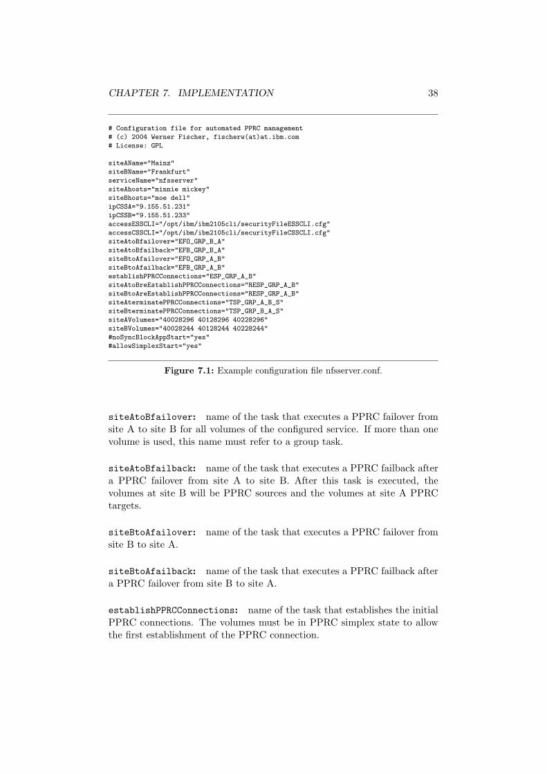
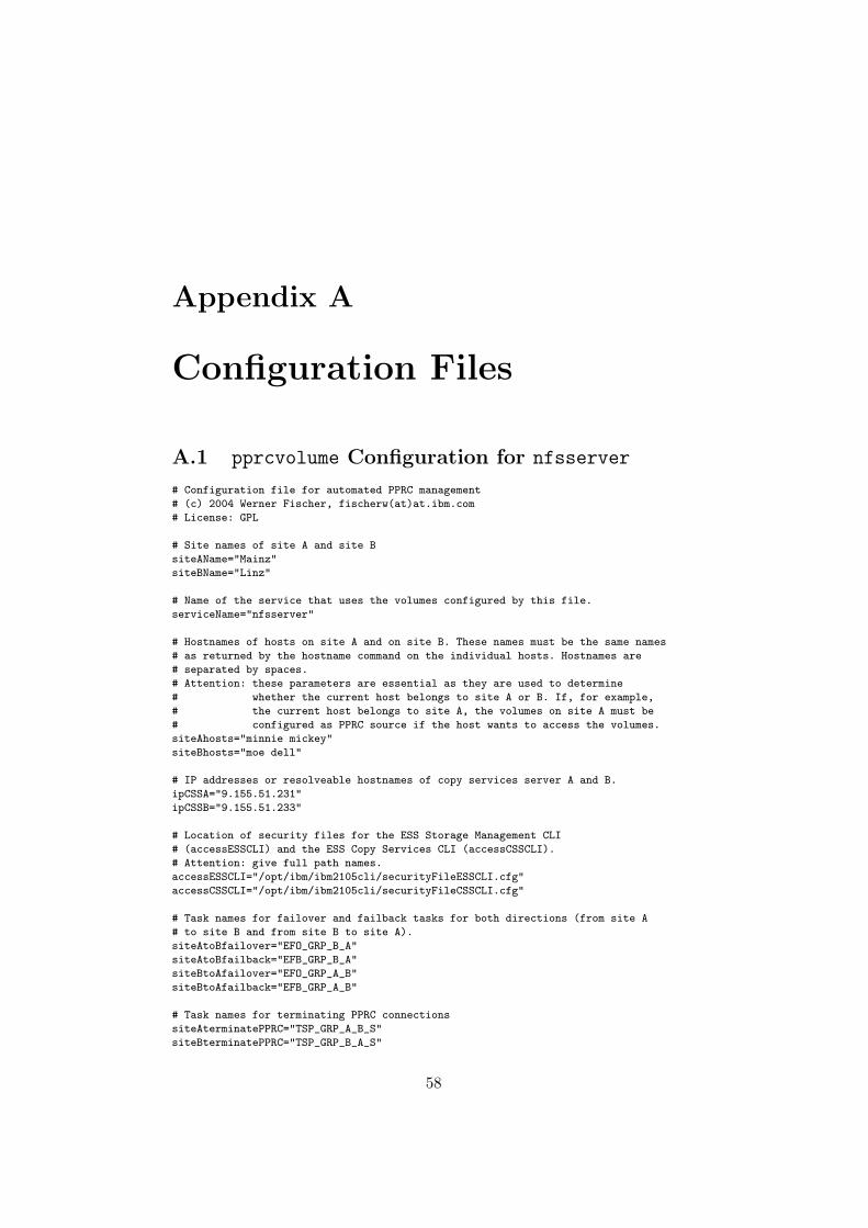
Every service that uses PPRC-mirrored volumes needs its own configurationfile. The values assigned to the variables provide all necessary informationto the pprcvolume script to automate the PPRC management. The config-uration files must be copied to every node at both sites. An example for anNFS server is shown in figure 7.1.
siteAName, siteBName: names of the two sites. This information is usedfor logging purposes.
serviceName: name of the service that uses the configured volumes. Thevalue is used for the name of the lock-file.
siteAhosts, siteBhosts: lists the names of all nodes in the cluster thatmay mount the configured volumes. The names must be the same as re-turned by the hostname command at the individual nodes. Host names areseparated by spaces. The variables are necessary to enable the pprcvolumescript to determine whether it is executed at site A or site B.
ipCSSA, ipCSSB: IP addresses or resolvable hostnames of Copy ServicesServer A and B. It is better to use IP addresses as they will also work ifname resolution is impossible. If hostnames are used, it is wise to insertthem with their corresponding IP addresses to /etc/hosts at each node.
accessESSCLI, accessCSSCLI: location of the access files for the ESSCLI(Enterprise Storage Server Command Line Interface) and the CSSCLI (CopyServices Server Command Line Interface).
CHAPTER 7. IMPLEMENTATION 38
# Configuration file for automated PPRC management
Figure 7.1: Example configuration file nfsserver.conf.
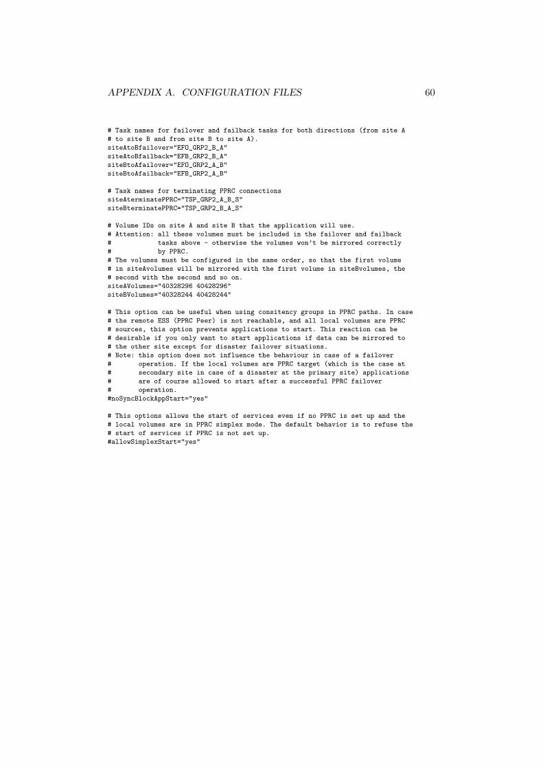
siteAtoBfailover: name of the task that executes a PPRC failover fromsite A to site B for all volumes of the configured service. If more than onevolume is used, this name must refer to a group task.
siteAtoBfailback: name of the task that executes a PPRC failback aftera PPRC failover from site A to site B. After this task is executed, thevolumes at site B will be PPRC sources and the volumes at site A PPRCtargets.
siteBtoAfailover: name of the task that executes a PPRC failover fromsite B to site A.
siteBtoAfailback: name of the task that executes a PPRC failback aftera PPRC failover from site B to site A.
establishPPRCConnections: name of the task that establishes the initialPPRC connections. The volumes must be in PPRC simplex state to allowthe first establishment of the PPRC connection.
CHAPTER 7. IMPLEMENTATION 39
siteAtoBreEstablishPPRCConnections: name of the task to re-establishPPRC Connections from site A to site B.
siteBtoAreEstablishPPRCConnections: name of the task to re-establishPPRC Connections from site B to site A.
siteAterminatePPRCConnections: name of the task that terminates PPRCconnections with the option “schedule task with source logical subsystem”at site A.
siteBterminatePPRCConnections: name of the task that terminates PPRCconnections with the option “schedule task with source logical subsystem”at site B.
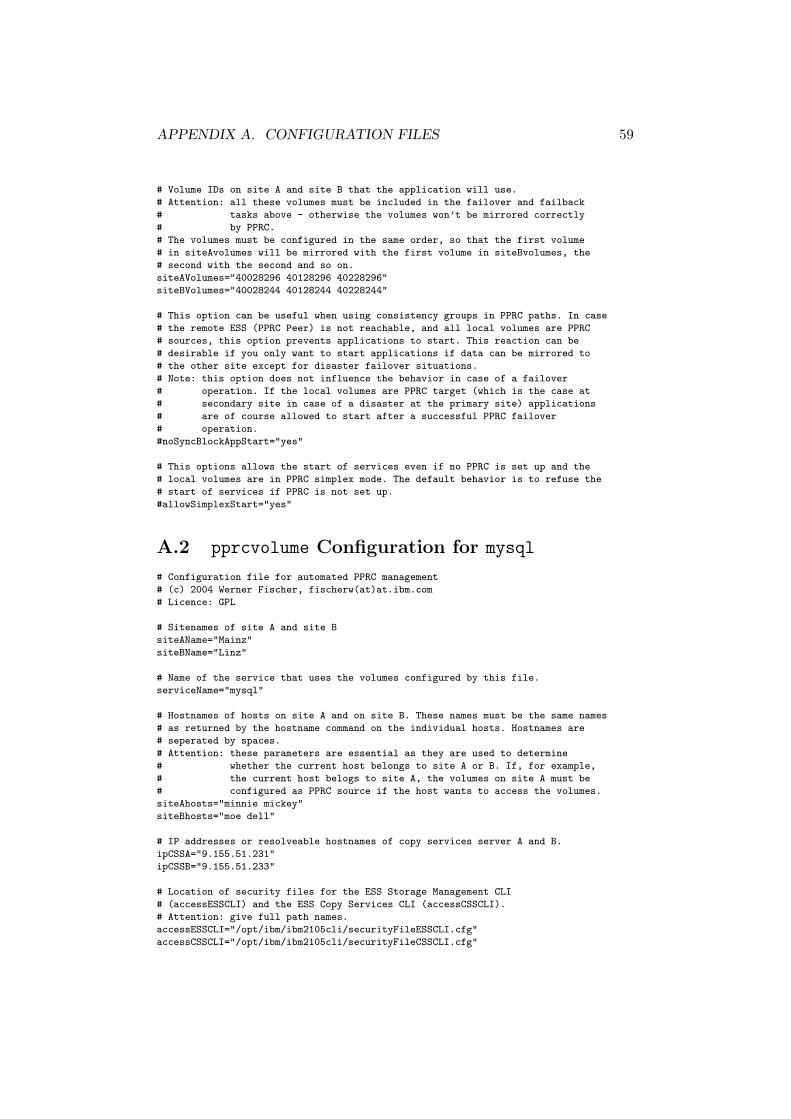
siteAvolumes, siteBvolumes: volume IDs at site A and site B that willbe used by the service. A volume ID contains a three digit volume numberand a 5 digit ESS serial number. siteAvolumes and siteBvolumes mustbe configured in the same order, so that the first volume in siteAvolumeswill be mirrored with the first volume in siteBvolumes and so on. VolumeIDs are separated by spaces.
noSyncBlockAppStart: option to block the start of applications if bothsites are not synchronous. This option is reasonable if PPRC consistencygroups are used. It has no impact on PPRC failover operations. If notdefined, noSyncBlockAppStart is set to no.
allowSimplexStart: allows the start of applications even if the volumesare in PPRC simplex state. This can be useful after a disaster that destroyedan ESS. In that case, the old PPRC connections should be terminated beforenew PPRC connections to a new ESS are established. To allow local fail-over even in those situations, allowSimplexStart must be configured toyes. This option should only be used temporarily. If not defined, it is setto no.
7.7 The pprcvolume Script
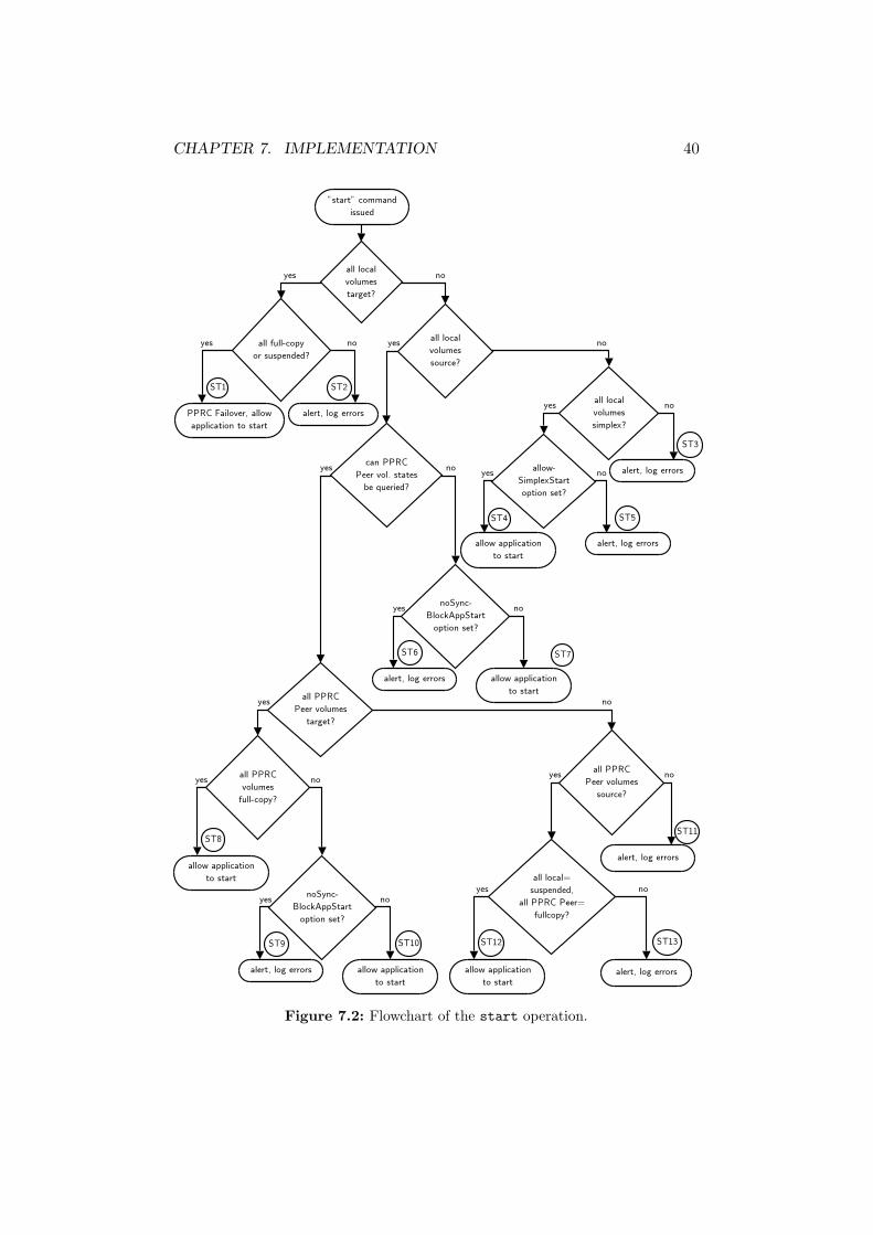
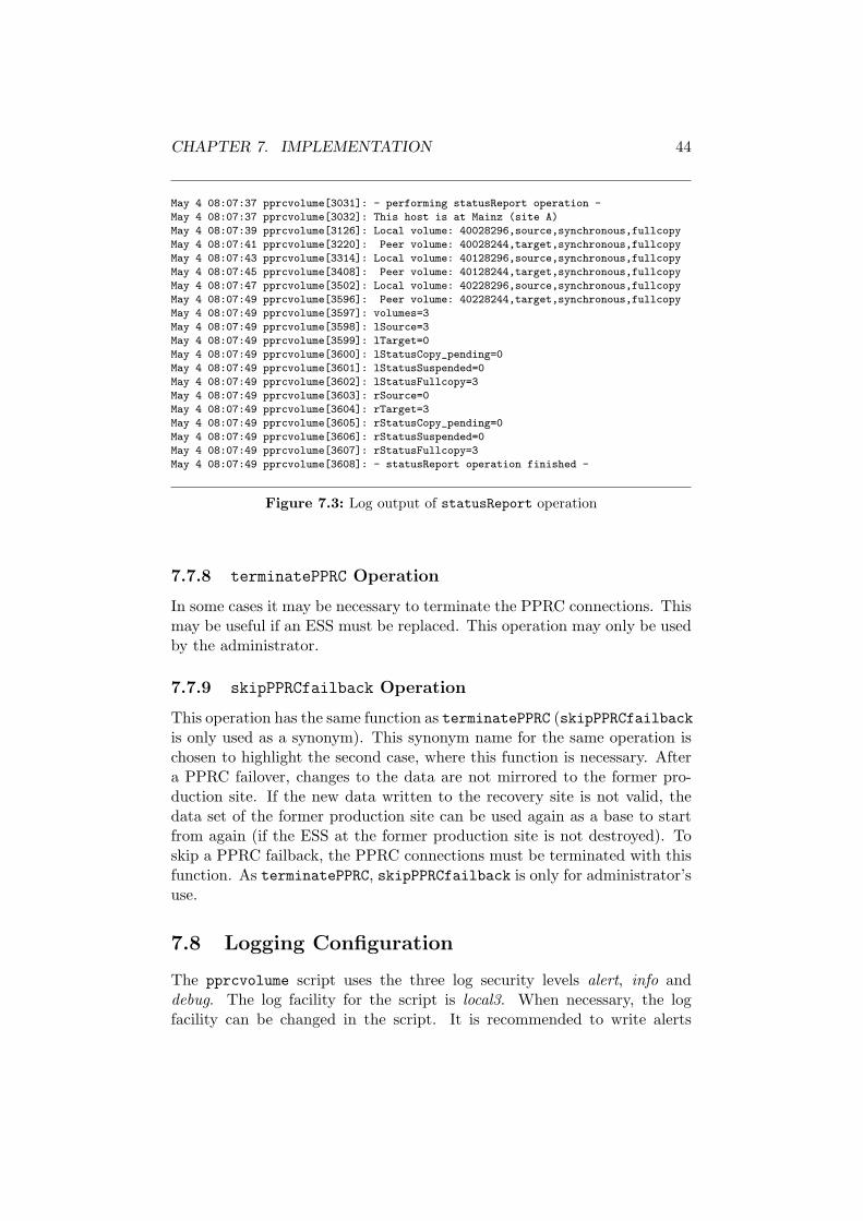
7.7.1 start Operation
The start operation is the core of the prototype. It contains the most com-plex functions of the prototype and ensures correct data replication states.To enable the start of applications, PPRC states must allow read/write ac-cess to the volumes. The start operation queries all volume states anddetermines if this is possible. In certain situations, it takes actions to bring
CHAPTER 7. IMPLEMENTATION 40
Figure 7.2: Flowchart of the start operation.
CHAPTER 7. IMPLEMENTATION 41
the volumes to a state that allows read/write access. If this is impossible,errors are logged and the script exits with a return code other than 0. Figure7.2 shows the flowchart of the start operation. The start operation is usedby the cluster manager during the startup of applications. A return code of0 must be mandatory for the cluster manager to mount the volumes.
Are all local volumes PPRC targets?
At first, the pprcvolume script checks whether all local volumes are PPRCtargets. PPRC target volumes can be used read-only to read the partitiontable during booting of a node. If the local volumes are PPRC targets infull copy or suspended state (state ST1 in the flowchart), a PPRC failoveroperation must be executed. After a successful PPRC failover, former PPRCtarget volumes will become PPRC source volumes in suspended state. Thisallows write access to the volumes. The states of the peer volumes in thePPRC pairs remain the same.
If not all PPRC target volumes are either full copy or suspended, noPPRC failover operation is executed and applications may not start (stateST2).
Are all local volumes PPRC sources?
If all local volumes are in PPRC source state, further investigations aboutthe state of the PPRC peer volumes are necessary. First of all, it mustbe checked if the PPRC peer volume states can be queried at all. This isnot possible if an ESS or its network connection fails. Depending on thenoSyncBlockAppStart option, applications are prohibited to start (statesST6 and ST7).
Are all PPRC peer volumes targets? If the peer volumes are PPRCtargets and in full copy state, applications are allowed to start (state ST8).This happens for example in a local fail-over situation or at the initial startof the application.
In case that the peer volumes are PPRC targets, but not all volumesare in full copy state, applications are prohibited to start depending on thenoSyncBlockAppStart option (states ST9 and ST10). This can happen ifall PPRC paths are down.
Are all PPRC peer volumes sources? If both the local and the peervolumes are PPRC sources, a PPRC failover operation may have happenedbefore. This situation can arise when a fail-over within the recovery site isnecessary after a disaster at the primary site. It is also possible that appli-cations should be started at the production site (after the application ran atthe recovery site), but no PPRC failback operation was executed before. In
CHAPTER 7. IMPLEMENTATION 42
the first case, the local PPRC source volumes should be in suspended state,remote PPRC source volumes in full copy state. If this is true, applicationsare allowed to start (state ST12), in other cases not (ST13).
If the PPRC peer volumes have different PPRC states, applications arenot allowed to start (ST11).
Are all local volumes PPRC simplex?
Depending on the allowSimplexStart option, applications may start (ST4)or not (ST5).
If the local volumes have different PPRC states, applications may notstart (state ST3).
7.7.2 stop Operation
This operation removes the lock-file that indicates the online state of thepprcvolume resource. The stop operation is used by the cluster managerif an application is switched to another node, or the application shouldgenerally be stopped.
7.7.3 PPRCfailback Operation
A PPRC failover operation is necessary during a failover of the applicationto the other site. This leaves the volumes at the former production site intheir current PPRC states. The volumes at the recovery site will becomePPRC sources in suspended state. Depending on the reason for the sitefail-over, the ESS at the production site may become available again.
The PPRC failback operation ensures a minimum re-synchronizationtime if new data tracks should be mirrored back to the original productionsite. This decision, if the new data should be mirrored back must be madeby the administrator. As a consequence, this operation is for administrator’suse only and must not be automatically executed by the cluster manager.Depending on the volume states at the original production site, the PPRCfailback operation executes different actions.
Volumes at the Production Site are PPRC Simplex: this will hap-pen if the ESS at the production site is replaced after a disaster.
By executing the PPRC failback, all data will be copied from the recoveryto the production site.
Volumes at the Production Site are PPRC Sources in full-copy orsuspended State without changed Data Tracks: this situation arisesif the ESS at the production site is not destroyed.
Only out-of-sync data will be copied back to the production site. Thisshortens the re-synchronization time.
CHAPTER 7. IMPLEMENTATION 43
Volumes at the Production Site are PPRC Sources in full-copy orsuspended State with changed Data Tracks: this situation shouldnever occur, as nodes at both sites must have written to the data. This canonly happen in a split brain situation, if operators grant operational quorumto both sites. This harms data consistency at application level. The dataconsistency at a single volume level is still preserved, But there is no chanceto merge the new data of both sites.
The ESS at the recovery site (which executed the PPRC failover) willdiscover which data tracks have been modified at each site. All these modi-fied data tracks will be copied back from the recovery to the production ESS.This also guarantees that changed data tracks at the former primary sitewill be overwritten, which is necessary to keep data consistency at volumelevel. All new data written to the primary site is lost.
7.7.4 status Operation
Determines the online state of the pprcvolume resource. If the lock-fileexists, the resource is treated as online. Cluster managers can use the statusoperation to monitor the state of the pprcvolume resource.
7.7.5 statusReport Operation
Gives an detailed overview about the current volume states. This operationis not used by the cluster manager. It is useful for the operator to checkvolume states without the ESS Copy Services Web User Interface. Theoutput of the operation is written to the log to ensure traceability. Anexample output is shown in figure 7.3.
7.7.6 establishPPRC Operation
Establishes the PPRC connections between the two sites. This operationcan be used for the initial synchronization or after a replacement of an ESS.It may only be executed by the administrator, never by a cluster manager.It copies the entire volumes to the other site.
7.7.7 reEstablishPPRC Operation
Similar to establishPPRC, reEstablishPPRC switches to synchronous repli-cation between the two sites. But this operation copies only out-of-synctracks to the other site. This shortens the re-synchronization time. The op-eration may only be used after an outage of all PPRC paths, which causesthe source volumes to go to suspended state. It may only be executed bythe administrator.
CHAPTER 7. IMPLEMENTATION 44
May 4 08:07:37 pprcvolume[3031]: - performing statusReport operation -
May 4 08:07:37 pprcvolume[3032]: This host is at Mainz (site A)
May 4 08:07:39 pprcvolume[3126]: Local volume: 40028296,source,synchronous,fullcopy
May 4 08:07:41 pprcvolume[3220]: Peer volume: 40028244,target,synchronous,fullcopy
May 4 08:07:43 pprcvolume[3314]: Local volume: 40128296,source,synchronous,fullcopy
May 4 08:07:45 pprcvolume[3408]: Peer volume: 40128244,target,synchronous,fullcopy
May 4 08:07:47 pprcvolume[3502]: Local volume: 40228296,source,synchronous,fullcopy
May 4 08:07:49 pprcvolume[3596]: Peer volume: 40228244,target,synchronous,fullcopy
May 4 08:07:49 pprcvolume[3597]: volumes=3
May 4 08:07:49 pprcvolume[3598]: lSource=3
May 4 08:07:49 pprcvolume[3599]: lTarget=0
May 4 08:07:49 pprcvolume[3600]: lStatusCopy_pending=0
May 4 08:07:49 pprcvolume[3601]: lStatusSuspended=0
May 4 08:07:49 pprcvolume[3602]: lStatusFullcopy=3
May 4 08:07:49 pprcvolume[3603]: rSource=0
May 4 08:07:49 pprcvolume[3604]: rTarget=3
May 4 08:07:49 pprcvolume[3605]: rStatusCopy_pending=0
May 4 08:07:49 pprcvolume[3606]: rStatusSuspended=0
May 4 08:07:49 pprcvolume[3607]: rStatusFullcopy=3
May 4 08:07:49 pprcvolume[3608]: - statusReport operation finished -
Figure 7.3: Log output of statusReport operation
7.7.8 terminatePPRC Operation
In some cases it may be necessary to terminate the PPRC connections. Thismay be useful if an ESS must be replaced. This operation may only be usedby the administrator.
7.7.9 skipPPRCfailback Operation
This operation has the same function as terminatePPRC (skipPPRCfailbackis only used as a synonym). This synonym name for the same operation ischosen to highlight the second case, where this function is necessary. Aftera PPRC failover, changes to the data are not mirrored to the former pro-duction site. If the new data written to the recovery site is not valid, thedata set of the former production site can be used again as a base to startfrom again (if the ESS at the former production site is not destroyed). Toskip a PPRC failback, the PPRC connections must be terminated with thisfunction. As terminatePPRC, skipPPRCfailback is only for administrator’suse.
7.8 Logging Configuration
The pprcvolume script uses the three log security levels alert, info anddebug. The log facility for the script is local3. When necessary, the logfacility can be changed in the script. It is recommended to write alerts
CHAPTER 7. IMPLEMENTATION 45
local3.alert -/var/log/pprcvolume.alert
local3.info -/var/log/pprcvolume.info
local3.debug -/var/log/pprcvolume.debug
Figure 7.4: Extract of the syslogd configuration file /etc/syslogd.conf.
to /var/log/messages. Logging information of the other two supportedsecurity levels should be written to different log files. Figure 7.4 shows anexample configuration for the syslog daemon.
Chapter 8
Tests
8.1 Test Environment
The test-setup is shown in figure 8.1. The zoning configuration of the InrangeFC/9000 director simulated four SAN-switches (two SAN-switches would belocated in each site).
The two sites were configured in an active/active setup in the test sce-nario. NFS and MySQL were used as example services. A test software
Figure 8.1: Test setup of the geographically dispersed cluster.
46
CHAPTER 8. TESTS 47
running on a sample client continuously wrote data to the NFS share. Thesample client was connected to the LAN of site B. PPRC paths were es-tablished without consistency group option. Hence in case of an outage ofall PPRC paths data writes to the PPRC source volume were allowed, al-though mirroring of the writes was impossible. As the test setup used atwo-site configuration, manual action was sometimes necessary to execute asite fail-over.
As the tests had to be done in a isolated testing network, no connectionsto time servers were possible. All nodes started with synchronous time,running a local ntp daemon. Driftfiles of all nodes were calculated duringone week running in a official network with access to time servers.
8.1.1 Tivoli System Automation Configuration
TSA was configured through a number of shell scripts and definition files.The configuration files for the test scenario can be found on the CD-ROM.
8.1.2 pprcvolume Configuration
The pprcvolume configuration files for the NFS and the MySQL server canbe found in appendix A.
8.2 Initial Setup and Synchronization
At the beginning, all necessary PPRC tasks had to be configured and thesynchronous PPRC connections manually established. This was done viathe ESS Specialist Web interface.
8.3 Site A down
Expected behavior: in case of a complete outage of a site the remainingsite brings up services. In a two-site configuration cluster nodes cannotdistinguish between a split brain and a disaster situation. Therefore manualintervention is necessary.
Test result: Nodes at the remaining site wrote warnings to their systemlog files (/var/log/messages) that indicated the PENDING QUORUM state:
Granting of operational quorum was necessary to bring up services thathad been running at site A. This was done with the following command,executed at the node moe (the command may have been executed at anynode at the remaining site B):
Apr 29 15:55:11 dell pprcvolume[26045]: This host is at Linz (site B)
...
Apr 29 15:56:44 dell /etc/safl/nfsserver/nfsserver:[28397]: NFS server started
If runact command was executed with Ownership=0, operational quo-rum would have been denied.
8.4 ESS A down
Expected behavior: an outage of a single ESS must lead to a site fail-over. It is noticed by the cluster manager’s file system monitoring script. Asapplications first try to fail-over to another node at the same site, the sitefail-over to the other site will be executed after all local nodes have tried tobring up the application.
Test result: Nodes that were using ESS A received SCSI errors after ESSA went down:Apr 29 21:35:47 minnie kernel: SCSI disk error : host 1 channel 0 id 0 lun 0 return
code = 8000002
Apr 29 21:35:47 minnie kernel: Current sd08:11: sense key Hardware Error
As soon as all paths of a vpath device were recognized as OFFLINE, themonitoring for this resource reported this to TSA. The NFS service wasstopped. The other node at the same site (mickey) tried to bring up the nfsservice twice. This failed as the ESS was not reachable. The pprcvolumescript logged the reason for this.
Apr 29 21:36:56 mickey pprcvolume[14321]: Alert: state (ST3), apps may NOT start, ex
iting with RC 1
Finally, node dell at site B started the nfs service.
Apr 29 16:35:25 mickey /etc/safl/nfsserver/nfsserver:[27846]: NFS server started
After the defective node was powered on again, the nfs service continuedto run on mickey.
CHAPTER 8. TESTS 50
8.6 Network Connection between Site A and SiteB down
Expected behavior: all running applications continue to run on theircurrent nodes. The outage of the network connection between the two sitesresults in two sub-clusters. Each of them will go to PENDING QUORUM state.If a site fail-over is necessary (e.g. from site A to site B), quorum mustbe denied for site A before the site B gets operational quorum. Nodes atsite A that are running services will be forced to reboot immediately afterquorum is denied through the runact command. After granting operationalquorum at site B, nodes at site B will bring up services that have beenrunning on site A. When the network connection is up again, a PPRC fail-back can be executed to mirror the new data back to site A. During thisre-synchronization, the data at site A is not consistent.
Test result: All nodes were still up and running. The cluster split upinto two sub-clusters. The output of the lsrpnode command showed theoperational state of the nodes in the sub-clusters (the output depended onthe node where the command was executed):
mickey:~ # lsrpnode
Name OpState RSCTVersion
mickey Online 2.3.2.2
dell Offline 2.3.2.2
minnie Online 2.3.2.2
moe Offline 2.3.2.2
mickey:~ #
moe:~ # lsrpnode
Name OpState RSCTVersion
mickey Offline 2.3.2.2
dell Online 2.3.2.2
minnie Offline 2.3.2.2
moe Online 2.3.2.2
moe:~ #
As the test client could not reach nodes at site A after the networkoutage, a site fail-over from site A to site B was necessary. This was doneby denying operational quorum at site A and granting operational quorumat site B.
After the runact command was executed on minnie, this node rebootedimmediately. The other node at site A (mickey) logged information aboutthe loss of quorum:
Apr 29 13:01:23 mickey ConfigRM[20140]: (Recorded using libct_ffdc.a cv 2):::Error I
signal 0 and returned: rsExecuteTask: Command successful
8.7 PPRC between ESS A and ESS B down
Expected behavior: as consistency groups are not activated, servicescontinue to run on their current nodes. If data is written to the PPRCsource volumes, the state of this PPRC sources changes from full-copy tosuspended. PPRC target volumes will remain in full-copy state, even if newdata is written to the associated PPRC source volumes.
Test result: After all PPRC paths failed, nodes that wrote to volumesgot SCSI errors:
Apr 29 14:58:27 minnie kernel: SCSI disk error : host 2 channel 0 id 0 lun 2 return
code = 8000002
Apr 29 14:58:27 minnie kernel: Current sd08:81: sense key Hardware Error
The PPRC state of the PPRC source volumes changed after they re-ceived write commands. To document this, a pprcvolume statusReportoperation was executed manually:
Expected behavior: Services continue to run at both sites. If additionalcluster resources fail, they will not be recovered as no site has quorum.
Test result: All nodes wrote warnings to /var/log/messages that the op-erational quorum state changes from HAS QUORUM to PENDING QUORUM (com-pare section 8.3).
8.9 Network at Site A down
Expected behavior: Active nodes at site A that are running servicesreboot immediately. Services at site A will be down. Manual action isnecessary to bring up these services at site B.
Test result: The node minnie rebooted immediately as it had been run-ning the NFS service. The other node at site A, mickey, continued to runbut logged information about the loss of quorum to /var/log/messages.After executing of the runact command with the parameter Ownership=1at moe (any node at site B would have been possible), the node dell broughtup the NFS service.
Apr 29 17:00:34 dell pprcvolume[19095]: This host is at Linz (site B)
CHAPTER 8. TESTS 53
...
Apr 29 17:02:08 dell /etc/safl/nfsserver/nfsserver:[21430]: NFS server started
8.10 Network completely down
Expected behavior: Nobody can use any services as the network is com-pletely down. The cluster will split up into four sub-clusters (each node willbuild a sub-cluster). Nodes that have been running services reboot imme-diately. Other nodes continue to run and indicate the loss of quorum. Allservices will be stopped. Data consistency is still preserved.
Test result: The nodes mickey and moe rebooted, as they had been run-ning services. The two other nodes remained up and indicated the loss ofquorum. All services went down.
8.11 Rolling Disaster Situation 1
In the simulated example, the rolling disaster leads to outages in the follow-ing order:
1. LAN connection of the ESS at site A fails.
2. LAN connection of node minnie fails two minutes later.
3. All other components at site A fail 10 minutes later.
Expected behavior: The outage of the LAN connection of ESS A causesno problems as long as no local fail-over is necessary. Immediately after theLAN connection of minnie fails, it reboots itself to protect shared resources.The other node at site A, mickey, tries to bring up the NFS service. Asthe PPRC state of the volumes of ESS A cannot be queried, the startup ofthe NFS service at mickey fails. After that, another node at site B bringsup the NFS service. When mickey also fails as all remaining components atsite A fail, the quorum state changes to PENDING QUORUM.
Test result: minnie rebooted after its LAN connection failed. The othernode at site A (mickey) tried to bring up the NFS service:
Apr 30 07:00:02 mickey RecoveryRM[22956]: (Recorded using libct_ffdc.a cv 2):::Error
As mickey could not start the NFS service, but was still part of thecluster, another node at site B brought up the NFS service without manualintervention.
Apr 30 07:12:22 dell /etc/safl/nfsserver/nfsserver:[9132]: NFS server started
8.12 Rolling Disaster Situation 2
In this simulated example, the rolling disaster leads to outages in the fol-lowing order:
1. LAN connection of the ESS at site A fails.
2. All PPRC links fail one minute later.
3. Node minnie fails two minutes later (loses all its power links).
Expected behavior: The outage of the LAN connection of ESS A causesno problems as long as no local fail-over is necessary. The outage of thePPRC links also does not disrupt the running services. After minnie fails,the other node at site A (mickey tries to bring up the NFS service. Thiswill fail, as the state of ESS A volumes cannot be queried. Finally, the NFSservice will be started at dell, causing a PPRC Failover from site A to siteB.
Test result: After minnie failed, mickey was able to bring up the NFSservice. This was not the expected behavior. The pprcvolume script gotwrong state information about volume states of ESS A:
Apr 30 08:04:20 mickey /etc/safl/nfsserver/nfsserver:[18967]: NFS server started
The script got information about all volume states from ESS B. Unfortu-nately, ESS B cached the volume states from ESS A. As the LAN connectionof ESS A broke first, followed by an outage of the PPRC links, ESS A couldnot send updated volume states to ESS B. A manually initiated pprcvolumestatusReport operation showed the correct state information two minuteslater:
There was no information about PPRC peer volumes, because the lo-cal PPRC states could not been queried (and the information about thecorresponding PPRC peer volumes comes from this query).
To prevent such situations, it is necessary to set a timeout value be-fore volume states are queried during a pprcvolume start operation. Thetimeout value depends on the maximum possible time an ESS caches volumestate information.
Also without a timeout value, data consistency will never be violated.In the worst case, services will be started on another node.
Chapter 9
Conclusions
9.1 Conclusions
1. A prototype for the automation of storage subsystem functions fordata replication has been developed. The implementation is shownwith Tivoli System Automation for Linux as an example of a clustermanager. The prototype itself works with any Linux cluster managerthat fulfills the requirements mentioned in section 7.2.
2. The prototype supports active-active configurations, two- and three-site setups (third site only for quorum) and allows each service to beindividually configured.
3. The implemented prototype meets all test conditions and handles dis-aster situations correctly.
4. If data writes are only allowed if the mirroring of the data workscorrectly, automation of the replication function for cluster managerintegration is very complicated (as shown in section 4.6).
9.2 Possibilities of Future Enhancements
As mentioned in [KP03, p. 7], some companies are giving serious consid-eration to a three-site strategy, each capable of running applications. Thiskind of design could allow automatic continuation of services after a disas-ter, even if data must be replicated to a second site to allow applicationsto run. Different applications may run at any of the three sites. Duringnormal operations, data is mirrored between all sites. In case of a disasterat one site, the remaining two sites start the application that ran at thedestroyed site. Data mirroring continues between the two remaining sites.The automation of data replication in such a configuration would be rathercomplex and will need future research.
56
CHAPTER 9. CONCLUSIONS 57
Another nice feature would be a support for multiple ESSes per site. Thecurrent prototype could support multiple ESSes, but for a single service themaximum is one ESS per site.
The implemented prototype supports synchronous replication only. Ad-ditional support for asynchronous replication would allow the use of theimplementation also for longer distances.
Appendix A
Configuration Files
A.1 pprcvolume Configuration for nfsserver
# Configuration file for automated PPRC management
# (c) 2004 Werner Fischer, fischerw(at)at.ibm.com
# License: GPL
# Site names of site A and site B
siteAName="Mainz"
siteBName="Linz"
# Name of the service that uses the volumes configured by this file.
serviceName="nfsserver"
# Hostnames of hosts on site A and on site B. These names must be the same names
# as returned by the hostname command on the individual hosts. Hostnames are
# separated by spaces.
# Attention: these parameters are essential as they are used to determine
# whether the current host belongs to site A or B. If, for example,
# the current host belongs to site A, the volumes on site A must be
# configured as PPRC source if the host wants to access the volumes.
siteAhosts="minnie mickey"
siteBhosts="moe dell"
# IP addresses or resolveable hostnames of copy services server A and B.
ipCSSA="9.155.51.231"
ipCSSB="9.155.51.233"
# Location of security files for the ESS Storage Management CLI
# (accessESSCLI) and the ESS Copy Services CLI (accessCSSCLI).
manuals/ . . . . . . . . directory containing manuals available in pdfformat
redbooks/ . . . . . . . . directory containing IBM redbookswhitepapers/ . . . . . . directory containing whitepapers available in
pdf format
Bibliography
[BK03] Jean S. Bozman and Dan Kusnetzky. Planning for Business Con-tinuity: HP-UX and Geographically Dispersed Clusters. Tech-nical report, International Data Corporation, Framingham, MA,USA, April 2003. IDC document 03C3670, online available atftp://ftp.hp.com/pub/enterprise/bus con IDC whitepaper.pdf.
[Cah03] Ben Cahill. Whatis OpenDLM. http://opendlm.sourceforge.net/docs.php, 2003. copy on CD-ROM.
[Cea02] Guesavo Castets et. al. IBM TotalStorage Enterprise StorageServer Model 800. International Business Machines Corporation,International Technical Support Organization, San Jose, CA, USA,second edition, October 2002. Redbook SG24-6424-01, copy onCD-ROM.
[Cea04] Guesavo Castets et. al. Implementing ESS Copy Services in OpenEnvironments. International Business Machines Corporation, In-ternational Technical Support Organization, San Jose, CA, USA,fourth edition, February 2004. Redbook SG24-5757-03, copy onCD-ROM.
[Dav00] Thomas Davis. Linux 2.4.26 kernel source, /documenta-tion/networking/bonding.txt. http://www.kernel.org/pub/linux/kernel/v2.4/linux-2.4.26.tar.bz2, 2000. copy on CD-ROM.
[Fre02] David Freund. Disaster Tolerant Unix: Removing the Last SinglePoint of Failure. Technical report, Illuminata, Inc., Nashua, NH,USA, August 2002. Online available at http://h71000.www7.hp.com/openvms/whitepapers/Illuminata.pdf.
[Hew03] Hewlett-Packard Co., Palo Alto, CA, USA. Arbitration For DataIntegrity in ServiceGuard Clusters, November 2003. ManufacturingPart Number: B7660-90078.
[Hew04] Hewlett-Packard Co., Palo Alto, CA, USA. Designing DisasterTolerant High Availability Clusters, March 2004. ManufacturingPart Number: B7660-90014.
63
BIBLIOGRAPHY 64
[Ins04] Institute of Electrical and Electronics Engineers, Inc., Piscataway,NJ, USA. IEEE Standard 802.1w-2001 for Local and metropolitanarea networks. Common specications. Part 3: Media Access Con-trol (MAC) Bridges, Amendment 2: Rapid Reconfiguration, 2004.online available at http://standards.ieee.org/getieee802/download/802.1w-2001.pdf.
[Int03a] International Business Machines Corporation, Armonk, New York,USA. HACMP Remote Copy: ESS PPRC Guide, July 2003. Pub-lication Number SC23-4863-00, online available at http://publibfp.boulder.ibm.com/epubs/pdf/c2348630.pdf.
[Int03b] International Business Machines Corporation, Armonk, New York,USA. IBM TotalStorage Enterprise Storage Server Command-LineInterfaces User’s Guide, November 2003. Publication NumberSC26-7494-03, online available at http://publibfp.boulder.ibm.com/epubs/pdf/f2bc1i03.pdf, copy on CD-ROM.
[Kea04] George Kozakos et. al. Implementing ESS Copy Services withIBM zSeries. International Business Machines Corporation, In-ternational Technical Support Organization, San Jose, CA, USA,February 2004. Redbook SG24-5680-03, copy on CD-ROM.
[KP03] R. F. Kern and V. T. Peltz. IBM Storage Infrastructure for Busi-ness Continuity. International Business Machines Corporation, Ar-monk, Now York, USA, Whitepaper, December 2003.
[Mit04] Christoph Mitasch. Server-Based Wide Area Data Replication forDisaster Recovery. Master’s thesis, Fachhochschule Hagenberg,Studiengang Computer- und Mediensicherheit, Hagenberg, Aus-tria, 2004.
[MS03] Evan Marcus and Hal Stern. Blueprints for High Availability. WileyPublishing, Indianapolis, IN, USA, second edition, 2003.
[Rei00] Philipp Reisner. Festplattenspiegelung ubers Netzwerk fur die Re-alisierung hochverfugbarer Server unter Linux. Master’s thesis,Technische Universitat Wien, Institut fur Computersprachen, Vi-enna, Austria, May 2000.
[Rob01] Alan Robertson. Resource fencing using STONITH. http://linux-ha.org/heartbeat/talks/ResourceFencing Stonith.pdf, 2001.
[Str02] Hartmut Streppel. Capmus Clusters Based on Sun Cluster 3.0 Soft-ware. Technical report, Sun Microsystems, Inc., Santa Clara, CA,USA, November 2002. Part Number 817-0369-10, online availableat http://www.sun.com/solutions/blueprints/1102/817-0369.pdf.
BIBLIOGRAPHY 65
[Sun04] Sun Microsystems, Inc., Santa Clara, CA, USA. Sun Cluster 3.xHardware Administration Manual for Solaris OS, January 2004.Part Number 817-0168-10, online available at http://docs-pdf.sun.com/817-0168/817-0168.pdf.
[TE03] Ulf Troppens and Rainer Erkens. Speichernetze - Grundlagenund Einsatz von Fibre Channel SAN, NAS, iSCSI und InfiniBand.dpunkt.verlag, Heidelberg, Germany, 2003.
[Wea02] Richard Wilkins et al. Disaster tolerant wolfpack geo-clusters.In Proceedings of the IEEE Internal Conference on Cluster Com-putung (CLUSTER’02), Piscataway, NJ, USA, 2002. Institute ofElectrical and Electronics Engineers, Inc.
[Wea04] Cathy Warrick et. al. IBM TotalStorage Solutions for DisasterRecovery. International Business Machines Corporation, Interna-tional Technical Support Organization, San Jose, CA, USA, Jan-uary 2004. Redbook SG24-6547-01, copy on CD-ROM.
[You97] Eric Youngdale. Linux 2.4.26 kernel source,/drivers/scsi/scsi queue.c. http://www.kernel.org/pub/linux/kernel/v2.4/linux-2.4.26.tar.bz2, 1997. copy on CD-ROM.