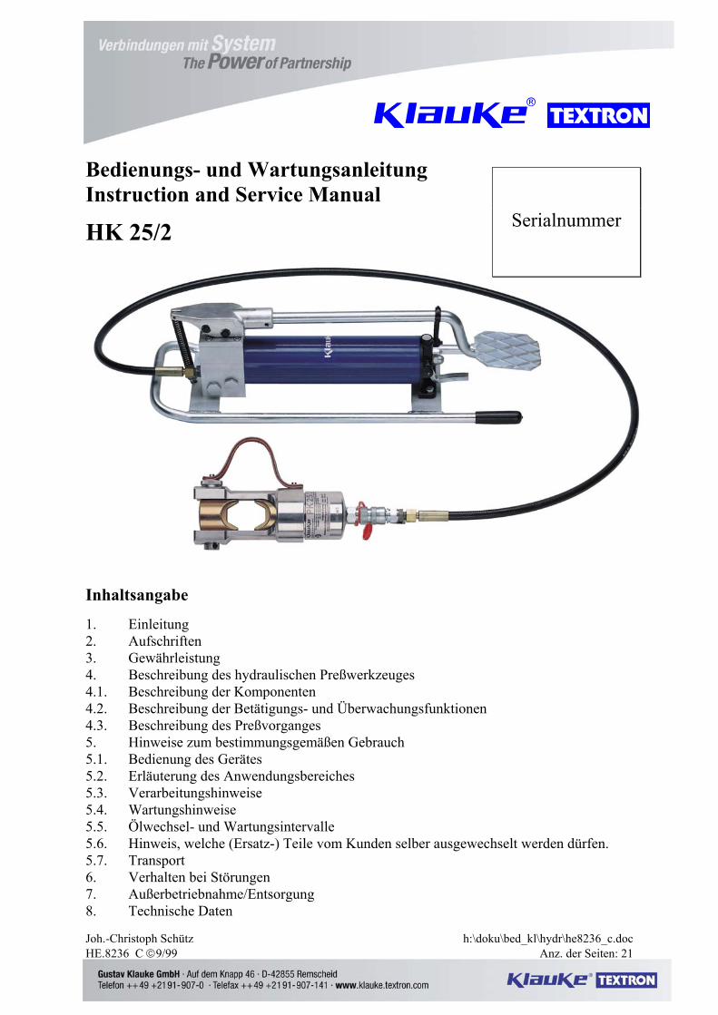
Joh.-Christoph Schütz h:\doku\bed_kl\hydr\he8236_c.doc HE.8236_C 9/99 Anz. der Seiten: 21 Bedienungs- und Wartungsanleitung Instruction and Service Manual HK 25/2 Inhaltsangabe 1. Einleitung 2. Aufschriften 3. Gewährleistung 4. Beschreibung des hydraulischen Preßwerkzeuges 4.1. Beschreibung der Komponenten 4.2. Beschreibung der Betätigungs- und Überwachungsfunktionen 4.3. Beschreibung des Preßvorganges 5. Hinweise zum bestimmungsgemäßen Gebrauch 5.1. Bedienung des Gerätes 5.2. Erläuterung des Anwendungsbereiches 5.3. Verarbeitungshinweise 5.4. Wartungshinweise 5.5. Ölwechsel- und Wartungsintervalle 5.6. Hinweis, welche (Ersatz-) Teile vom Kunden selber ausgewechselt werden dürfen. 5.7. Transport 6. Verhalten bei Störungen 7. Außerbetriebnahme/Entsorgung 8. Technische Daten Serialnummer
Transcript
Joh.-Christoph Schütz h:\doku\bed_kl\hydr\he8236_c.doc HE.8236_C 9/99 Anz. der Seiten: 21
Bedienungs- und Wartungsanleitung Instruction and Service Manual
HK 25/2
Inhaltsangabe
1. Einleitung 2. Aufschriften 3. Gewährleistung 4. Beschreibung des hydraulischen Preßwerkzeuges 4.1. Beschreibung der Komponenten 4.2. Beschreibung der Betätigungs- und Überwachungsfunktionen 4.3. Beschreibung des Preßvorganges 5. Hinweise zum bestimmungsgemäßen Gebrauch 5.1. Bedienung des Gerätes 5.2. Erläuterung des Anwendungsbereiches 5.3. Verarbeitungshinweise 5.4. Wartungshinweise 5.5. Ölwechsel- und Wartungsintervalle 5.6. Hinweis, welche (Ersatz-) Teile vom Kunden selber ausgewechselt werden dürfen. 5.7. Transport 6. Verhalten bei Störungen 7. Außerbetriebnahme/Entsorgung 8. Technische Daten
Serialnummer
Bedienungsanleitung HK 25/2 Seite 2 ___________________________________________________________________________ Kurzinspektion vor Inbetriebnahme Bitte prüfen Sie, ob Sie alle im Lieferumfang angeführten Teile erhalten haben. Lieferumfang: 1 hydraulische Fußpumpe Typ FHP 2 1 2m Hochdruckschlauch mit Kupplung 1 Preßkopf Typ PK 25/2 1 Bedienungsanleitung Bitte prüfen Sie anhand Ihres Lieferscheins, ob Sie auch die von Ihnen gewünschten Zubehörteile erhalten haben. Bedienungsanleitung für das hydraulische Preßgerät Typ HK 25/2, Seriennummer ..................... 1. Einleitung • Vor Inbetriebnahme Ihres Preßgerätes lesen Sie sich die Bedienungsanleitung sorgfältig durch. • Benutzen Sie dieses Gerät ausschließlich für den bestimmungsgemäßen Gebrauch. • Einbau und Montage von Verbindungsmaterial mit Hilfe dieses Aggregates darf nur durch eine elektrotechnisch unterwiesene Person erfolgen. Das Mindestalter beträgt 16 Jahre. • Diese Bedienungsanleitung ist während der gesamten Lebensdauer des Gerätes mitzuführen. • Der Betreiber muß - dem Bediener die Betriebsanleitung zugänglich machen und - sich vergewissern, daß der Bediener sie gelesen und verstanden hat. 2. Aufschriften An dem Pumpaggregat und dem Preßkopf finden Sie jeweils einen Aufkleber mit Firmenlogo/Firmennamen, Typenangabe, Seriennummer und dem zulässigen Betriebsüberdruck. Der Hydraulikschlauch ist mit Herstellerangabe, Typ, Nennweite und Herstellungsjahr versehen. Die Nennweite kann an den letzten beiden Ziffern der Typangabe abgelesen werden. 3. Gewährleistung Die Gewährleistung beträgt bei sachgemäßer Bedienung und unter Einhaltung der geforderten regelmäßigen Kontrollen 1 Jahr ab Lieferdatum.
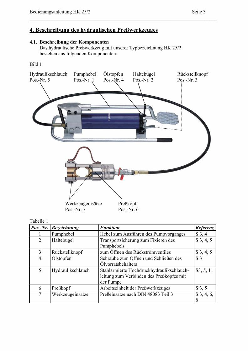
Bedienungsanleitung HK 25/2 Seite 3 ___________________________________________________________________________ 4. Beschreibung des hydraulischen Preßwerkzeuges 4.1. Beschreibung der Komponenten Das hydraulische Preßwerkzeug mit unserer Typbezeichnung HK 25/2 bestehen aus folgenden Komponenten: Bild 1
1 Pumphebel Hebel zum Ausführen des Pumpvorganges S 3, 4 2 Haltebügel Transportsicherung zum Fixieren des
Pumphebels S 3, 4, 5
3 Rückstellknopf zum Öffnen des Rückströmventiles S 3, 4, 5 4 Ölstopfen Schraube zum Öffnen und Schließen des
Ölvorratsbehälters S 3
5 Hydraulikschlauch Stahlarmierte Hochdruckhydraulikschlauch-leitung zum Verbinden des Preßkopfes mit der Pumpe
S3, 5, 11
6 Preßkopf Arbeitseinheit der Preßwerkzeuges S 3, 5 7 Werkzeugeinsätze Preßeinsätze nach DIN 48083 Teil 3 S 3, 4, 6,
8
Bedienungsanleitung HK 25/2 Seite 4 ___________________________________________________________________________ 4.2. Beschreibung der Betätigungs- und Überwachungsfunktionen
Zum Entfernen der Transportsicherung wird der Pumpenhebel (Pos.-Nr. 1) nach unten in Richtung des Pumpenkörpers gedrückt und der Haltebügel (Pos.-Nr. 2) zur Seite geschwenkt. Durch Fußbetätigung des Pumpenhebels wird die Pressung eingeleitet. Nach kontinuier-licher Betätigung des Fußhebels schaltet die Pumpe nach einem hörbaren Klicken bei 700 bar selbstständig ab. Die Pumpe ist mit einem Doppelkolben ausgestattet, die ein schnelles Heranfahren der Preßeinsätze im Niederdruckbereich ermöglicht und dann automatisch in die Hochdruckphase, d.h. die eigentliche Arbeitsphase, umschaltet. Nach Ansprechen des Überdruckventils wird der Kolben des Preßwerkzeuges durch Betätigung des Rückstellknopfes (Pos.-Nr. 3) der Fußpumpe zurückgefahren. Der Druckaufbau kann jederzeit an einem an der Pumpe auf Wunsch angebrachten Manometer verfolgt werden.
4.3. Beschreibung des Preßvorganges Beim Preßvorgang werden die Werkzeugeinsätze gegeneinander gefahren. Der auf das Kabel aufgeschobene Kabelschuh/Verbinder befindet sich in der feststehenden Hälfte des Preßeinsatzes. Der auf der Kolbenstange sitzende bewegliche Teil des Preßeinsatzes bewegt sich dabei auf die Preßstelle zu. Eine Pressung ist abgeschlossen, wenn die Werkzeugeinsätze (Pos.-Nr. 7) zusammen-gefahren sind und der zulässige Betriebsüberdruck erreicht wurde. Bei Erreichen des zul. Betriebsüberdrucks öffnet sich das Überdruckventil und leitet das Druckmedium (Hydrauliköl) wieder in den Vorratbehälter um. Die Angabe der Höhe des zul. Betriebs-überdruckes befindet sich sowohl auf dem Preßkopf als auch auf dem Pumpaggregat. Weitere Hinweise zur Verpressung von Verbindungsmaterialien entnehmen Sie bitte unserem Montagehinweisen im Katalog.
5. Hinweise zum bestimmungsgemäßen Gebrauch Es muß darauf geachtet werden, daß das Pumpaggregat standsicher auf einer ebenen Fläche mit einem maximalen Neigungswinkel von 15° aufgestellt wird. In Verbindung mit einem 2 m Hochdruckschlauch (Pos.-Nr. 5) ist das Arbeiten im Kabel-graben nicht möglich. Für diese Anwendung wird mindestens ein 3 m Schlauch benötigt.
5.1. Bedienung des Gerätes 1. Anschluß des Preßkopfes (Pos.-Nr. 7) an die Fußpumpe und vollständiges Ausrollen des
Hochdruckschlauches.
Achtung Pumpe niemals ohne Preßkopf betreiben!
Bedienungsanleitung HK 25/2 Seite 5 ___________________________________________________________________________
Achtung Vor Inbetriebnahme Ölstand prüfen und ggf. auffüllen.
2. Entfernen der Transportsicherung (Pos.-Nr. 2), Einsetzen geeigneter Werkzeugeinsätze
(Pos.-Nr. 7) und Positionierung des Preßkopfes (Pos.-Nr. 6). Stellen Sie vor Beginn des Preßvorganges sicher, daß der Bolzen vollständig in den Preßkopf eingeschoben ist.
3. Durchführung des Preßvorganges wie in Kap. 4.3. beschrieben. 4. Nach Erreichen des max. Betriebsdruckes wird der Rückstellknopf (Pos.-Nr. 3) betätigt
und das Verbindungsmaterial aus dem Preßkopf (Pos.-Nr. 6) entfernt.
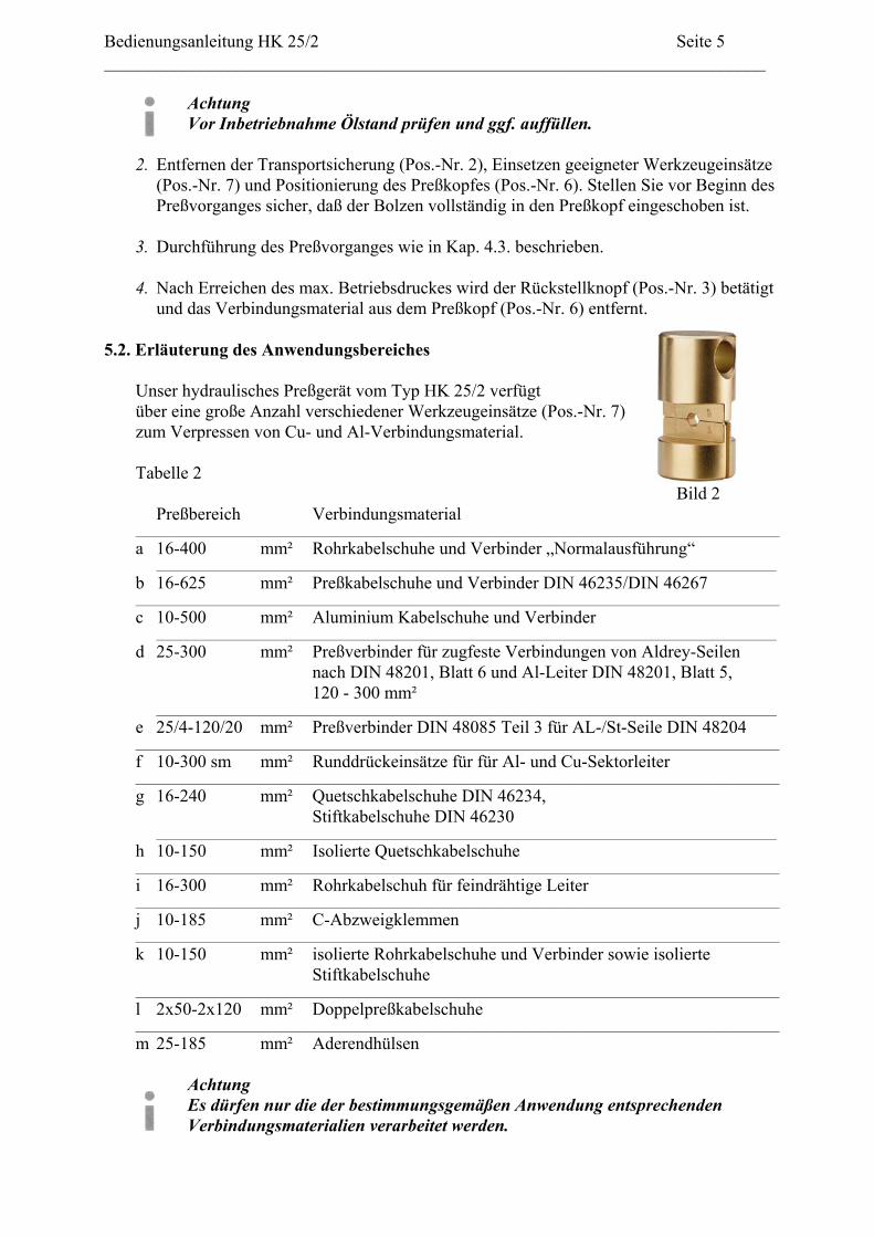
5.2. Erläuterung des Anwendungsbereiches Unser hydraulisches Preßgerät vom Typ HK 25/2 verfügt über eine große Anzahl verschiedener Werkzeugeinsätze (Pos.-Nr. 7) zum Verpressen von Cu- und Al-Verbindungsmaterial. Tabelle 2 Bild 2 Preßbereich Verbindungsmaterial _____________________________________________________________________________________________________________
a 16-400 mm² Rohrkabelschuhe und Verbinder „Normalausführung“ _________________________________________________________________________________________________________
b 16-625 mm² Preßkabelschuhe und Verbinder DIN 46235/DIN 46267 _____________________________________________________________________________________________________________
c 10-500 mm² Aluminium Kabelschuhe und Verbinder _________________________________________________________________________________________________________
d 25-300 mm² Preßverbinder für zugfeste Verbindungen von Aldrey-Seilen nach DIN 48201, Blatt 6 und Al-Leiter DIN 48201, Blatt 5, 120 - 300 mm² _________________________________________________________________________________________________________
e 25/4-120/20 mm² Preßverbinder DIN 48085 Teil 3 für AL-/St-Seile DIN 48204 _____________________________________________________________________________________________________________
f 10-300 sm mm² Runddrückeinsätze für für Al- und Cu-Sektorleiter _____________________________________________________________________________________________________________
g 16-240 mm² Quetschkabelschuhe DIN 46234, Stiftkabelschuhe DIN 46230 _________________________________________________________________________________________________________
h 10-150 mm² Isolierte Quetschkabelschuhe _____________________________________________________________________________________________________________
i 16-300 mm² Rohrkabelschuh für feindrähtige Leiter _____________________________________________________________________________________________________________
k 10-150 mm² isolierte Rohrkabelschuhe und Verbinder sowie isolierte Stiftkabelschuhe _____________________________________________________________________________________________________________
l 2x50-2x120 mm² Doppelpreßkabelschuhe _____________________________________________________________________________________________________________
m 25-185 mm² Aderendhülsen
Achtung Es dürfen nur die der bestimmungsgemäßen Anwendung entsprechenden Verbindungsmaterialien verarbeitet werden.
Bedienungsanleitung HK 25/2 Seite 6 ___________________________________________________________________________
Sollten andere Verbindungsmaterialien verpreßt werden müssen, ist eine Rücksprache mit dem Werk zwingend erforderlich.
Achtung Desweiteren dürfen keine unter Spannung stehenden Teile verpreßt werden.
Vor Arbeitsbeginn ist ein spannungsfreier Zustand der zu verpressenden Verbindung sicherzustellen. Das Gerät kann in einem Temperaturbereich von -20°C bis +40°C sowohl im Innen- als auch im Aussenbereich eingesetzt werden.
5.3. Verarbeitungshinweise Bei weiteren über die in Tabelle 2&3 angeführten Anwendungsfälle hinaus ist zwingend Rücksprache mit dem Werk zu halten. Tabelle 3 Kennzeichnung der Werkzeugeinsätze
Kennzeichnung Zuordn. Tab. 2
Preßeinsätze außen Preßprofil
Oberfläche des Preßeinsatzes
Preß- breite
a Normalausführung CU, QS QS gelb chromatiert 10-20 mm
b DIN 46235/ DIN46267
CU, QS, DIN 46235
Kennzahl gelb chromatiert 10-17 mm
c Aluminium AL, QS Kennzahl blau verzinkt 12-17 mm
h isol. Quetsch-KS ISQ, QS QS gelb chromatiert - i KS f. feindr. Leiter F, QS QS, F gelb chromatiert - j C-Abzweigkl. C, QS - gelb chromatiert - k isol. Rohr-KS+VB IS, QS - gelb chromatiert - l Doppelpreß-KS QS QS gelb chromatiert - m AEH DIN 46228 AE, QS - gelb chromatiert -
A b k ü z u n g e n : K S - K a b e l s c h u h e , V B - V e r b i n d e r , A E H - A d e r e n d h ü l s e n , Q S - Q u e r s c h n i t t
Mit den in Tabelle 3 Abs. a aufgeführten Einsätzen dürfen ausschließlich handelsübliche Klauke Rohrkabelschuhe und Verbinder verarbeitet werden. Eine Verpressung von handelsüblichen Kabelschuhen und Verbindern anderer Hersteller ergibt keine ordnungsgemäße Verpressung.
Bedienungsanleitung HK 25/2 Seite 7 ___________________________________________________________________________
Mit den in Tabelle 3 Abs. j beschriebenen Einsätzen für C-Klemmen dürfen ausschließlich Klauke-Klemmen verpreßt werden. Bei C-Klemmen anderer Hersteller kann keine Garantie für eine ordnungsgemäße Verpressung gegeben werden. Gleiches gilt im Übrigen für das Verbindungsmaterial aus Tab. 3h, 3i, 3k und 3l. Trotz gleicher Kennzahl sind die Preßbreiten bei Cu- und Al-Preßkabelschuhen und Verbindern unterschiedlich. Zur Kennzeichnung sind die Einsätze neben der Aufschrift noch farblich unterschiedlich ausgeführt.
Achtung Es dürfen auch bei gleicher Kennzahl nur die für das Material vorgesehenen Werkzeugeinsätze verwendet werden.
5.4. Wartungshinweise
Das hydraulische Aggregat ist nach jedem Gebrauch zu reinigen und ein trockener Zustand vor Einlagerung sicherzustellen. Das Aggregat ist weitgehend wartungsfrei. Lediglich der Ölstand ist regelmäßig zu kontrollieren und das Aggregat ist nach möglichen Beschädigungen zu untersuchen. Zur Ölstandskontrolle den Ölstopfen (Pos.-Nr. 4) aufdrehen und optisch den Ölstand kontrollieren. Ist der Ölstand zu niedrig, muß entsprechend Öl nachgefüllt werden. Nach erfolgter Wartung den Ölstopfen wieder aufschrauben. Der Hydraulikschlauch und die Armaturen müssen vor und nach der Anwendung auf Beschädigungen und Undichtigkeiten hin überprüft werden. Folgende legierte Hydrauliköle können verwendet werden: Tabelle 4 Sorte Temperaturbereich Viskositätsklasse Qualitätsstufe _____________________________________________________________________________________________________
AVIA HVI 15 -20°C bis +40°C VG 15 HLP Shell Tellus T 15 -20°C bis +40°C VG 15 HLP Mobil DTE 11 -20°C bis +40°C VG 15 HLP NUTO H 15 -20°C bis +40°C VG 15 HLP Rando HD - Z15 -20°C bis +40°C VG 15 HLP Agip OSO 15 -20°C bis +40°C VG 15 HLP BP Energol HLP 15 -20°C bis +40°C VG 15 HLP Es können auch andere vergleichbare Hydrauliköle verwendet werden.
Bedienungsanleitung HK 25/2 Seite 8 ___________________________________________________________________________ 5.5. Ölwechsel- und Wartungsintervalle.
Es ist empfehlenswert, das Gerät in regelmäßigen Abständen durch einen Sachkundigen zu warten, um einen einwandfreien Zustand vor dem nächsten Gebrauch zu gewährleisten. Tabelle 5 Wartungsplan:
Reinigen nach jedem Gebrauch Bediener Ölstand prüfen wöchentlich Bediener Hochdruckschlauch prüfen wöchentlich Sachkundigen Hydrauliköl wechseln jährlich Werk/Sachkundigen Das Hydrauliköl ist nach spätestens einem Jahr oder bei häufigem Gebrauch nach ca. 10.000 Verpressungen komplett auszutauschen. Wir empfehlen, diesen Ölwechsel im Werk ausführen zu lassen.
Achtung Bitte verwenden Sie nur sauberes, einwandfreies Hydrauliköl (AVIA HVI 15 und andere Hydrauliköle gleicher Qualität). Achtung Hydrauliköle können Hautausschläge und andere Gesundheitsschädigungen hervorrufen. Vermeiden Sie längeren Hautkontakt. Waschen Sie sich nach jedem Kontakt gründlich. Achtung Verschüttetes Hydrauliköl muß sofort mit Saugmaterial gebunden werden.
5.6. Hinweis welche (Ersatz-) Teile vom Kunden selber ausgetauscht werden dürfen.
Innerhalb des Gewährleistungszeitraums darf vom Kunden nur das Öl gewechselt werden.
Achtung Versiegelung der Druckeinstellschraube nicht beschädigen!
Führen Sie keine eigenen Reparaturen durch und entfernen Sie keine Bauteile wie Schrauben oder andere Komponenten.
5.7. Transport Das Hydraulikaggregat sollte, um Beschädigungen beim Transport zu vermeiden, immer in einem Transportkoffer transportiert werden. Dabei ist darauf zu achten, daß der Hydraulik-schlauch (Pos.-Nr. 5) ordentlich aufgerollt wird. Der Mindestknickradius von max. 70 mm darf nicht unterschritten werden.
Bedienungsanleitung HK 25/2 Seite 9 ___________________________________________________________________________
6. Verhalten bei Störungen
Erreicht die Pumpe nicht Ihren vollen Druck, so kann Luft in das System eingedrungen sein. Abhilfe: Halten Sie bitte den Preßkopf tiefer als die elektrische Pumpe und betätigen Sie den Pumphebel bis die Preßeinsätze ihre Endlage erreicht haben. Diesen Vorgang wiederholen Sie bitte 2-3 mal. Erreicht die Pumpe dann noch nicht den vollen Druck, so muß der Entlüftungsvorgang wiederholt werden. Tritt Hydrauliköl an der Pumpe oder am Preßkopf aus, muß das jeweilige Bauteil oder ggf. das gesamte Aggregat zur Reparatur ins Werk eingeschickt werden.
7. Außerbetriebnahme/Entsorgung Auch bei qualitativ hochwertigen Geräten ist irgendwann der Zeitpunkt gekommen, an dem die Entsorgungsfrage gestellt werden muß. Die Entsorgung der einzelnen Komponenten des Aggregates muß getrennt erfolgen. Dabei muß zuerst das Öl abgelassen und an speziellen Abnahmestellen entsorgt werden.
Achtung Hydrauliköle stellen eine Gefahr für das Grundwasser dar. Unkontrolliertes Ablassen oder unsachgemäße Entsorgung steht unter Strafe. (Umwelthaftungsgesetz)
Als nächstes muß der Schlauch abgeschraubt werden und das im Schlauch befindliche Öl mit dem Öl aus der Pumpe entsorgt werden. Auch der Schlauch muß als ölverschmutztes Betriebsmittel speziell entsorgt werden. Die restlichen Teile des Aggregates müssen nach den jeweiligen Umweltstandards entsorgt werden. Wir empfehlen wegen möglicher Umweltverschmutzung die Entsorgung durch zugelassene Fachunternehmen vornehmen zu lassen. Eine kostenfreie Rücknahme des Altgerätes durch den Hersteller kann nicht zugesagt werden.
Bedienungsanleitung HK 25/2 Seite 10 ___________________________________________________________________________ 8. Technische Daten
Preßkraft (PK 25/2): 250 kN Gewicht (PK 25/2): 5,25 kg Temperaturbereich des Hydrauliköls: -20°C bis +40°C Schlauchlänge: 2 m Hydrauliköl: "AVIA HVI 15" Betriebsdruck: 700 bar Eingefüllte Ölmenge 0,4 l Gesamtgewicht: 17,55 kg Symbole
Sicherheitstechnische Hinweise Bitte unbedingt beachten, um Personen- und Umweltschäden zu vermeiden. Anwendungstechnische Hinweise Bitte unbedingt beachten, um Schäden am Gerät zu vermeiden.
Anmerkung Diese Bedienungsanleitung jederzeit kostenlos unter der Nr. HE.8236_C nachbestellt werden.
Joh.-Christoph Schütz h:\doku\bed_kl\hydr\he8236_c.doc HE.8236_C Version 1.a 1/98 Anz. der Seiten: 21
Auf dem Knapp 46 Tel.: ++49 (0)2191/907-0 D-42855 Remscheid Fax: ++49 (0)2191/907-141 ____________________________________________________________________________
Instruction Manual
Index 1. Introduction 2. Labels 3. Warranty 4. Description of the hydraulic crimping unit 4.1. Description of the components 4.2. Description of the operation 4.3. Description of the crimping processes 5. Remarks with respect to the determined use 5.1. Operation of the unit 5.2. Explanation of the application range 5.3. Mounting instructions 5.4. Service and Maintenance instructions 5.5. Oil changing cycles 5.6. Storage and transport of the crimping unit 5.7. Reference as to which (spare-) parts can be exchanged by the customer 6. Troubleshooting 7. Putting out of service/waste disposal 8. Technical data
HK 25/2
Instruction manual HK 25/2 page 12 __________________________________________________________________________ Brief inspection before putting into service Please check immediately if you received all parts mentioned in our basic supply. Basic supply: 1 Hydraulic foot pump Type FHP 2 1 2 m high pressure hose with coupling 1 Crimping head Type PK 25/2 1 Instruction manual Please check according your bill of delivery if you received all requested dies. Instruction Manual for the hydraulic crimping unit Type HK 25/2, Serial-No. ............................ 1. Introduction Before starting to use the tool please read the instruction manual carefully. Use this tool exclusively for its determined use. Mounting and assembly of connecting material with the help of this tool must only be performed by specially trained personnel. The minimum age is 16 years. This instruction manual must be carried along during the entire life span of that tool. The operator must - guaranty the availability of the instruction manual for the user and - make sure, that the user has read and understood the instruction manual. 2. Labels On the labels fixed on the unit you’ll find the type specification, name of the manufacturer and/or the company logo and the Serial No.. 3. Warranty If correct operation is guaranteed and regular service is provided our warranty is 1 year from the time of delivery.
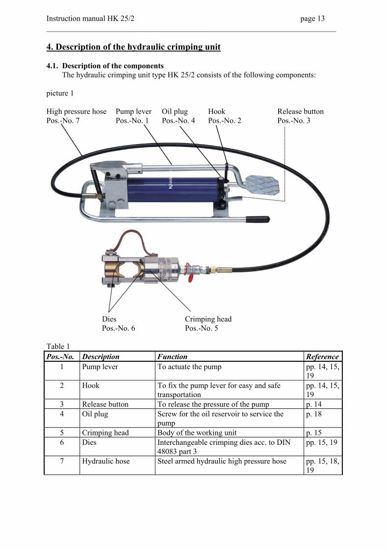
Instruction manual HK 25/2 page 13 __________________________________________________________________________ 4. Description of the hydraulic crimping unit 4.1. Description of the components The hydraulic crimping unit type HK 25/2 consists of the following components: picture 1 High pressure hose Pump lever Oil plug Hook Release button Pos.-No. 7 Pos.-No. 1 Pos.-No. 4 Pos.-No. 2 Pos.-No. 3
Dies Crimping head Pos.-No. 6 Pos.-No. 5
Table 1 Pos.-No. Description Function Reference
1 Pump lever To actuate the pump pp. 14, 15, 19
2 Hook To fix the pump lever for easy and safe transportation
pp. 14, 15, 19
3 Release button To release the pressure of the pump p. 14 4 Oil plug Screw for the oil reservoir to service the
pump p. 18
5 Crimping head Body of the working unit p. 15 6 Dies Interchangeable crimping dies acc. to DIN
48083 part 3 pp. 15, 19
7 Hydraulic hose Steel armed hydraulic high pressure hose pp. 15, 18, 19
Instruction manual HK 25/2 page 14 __________________________________________________________________________ 4.2. Description of the operation
In order to remove the hook (Pos.-No. 2) the pump lever (Pos.-No. 1) will be pressed towards the body of the pump so that the hook can be pushed aside and thus releasing the pump lever. By actuating the pump lever with the foot the crimping cycle will be initiated. After continuously actuating the pump lever the pump will switch off automatically when reaching the max. operating pressure at 700 bar. Reaching this point will be indicated by an audible „click“. The pump has a double piston which allows a fast approach of the dies to the cable lug in a low pressure mode. When the compression starts the pump will automatically switch over to the high pressure mode. After reaching the max. operating pressure the piston can be returned into the starting position by actuating the release button (Pos.-No. 3). If a pressure pick up is available the pressure increase can be observed.
4.3 Description of the crimping procedure A crimping process is characterized by the closing motion of the dies. The cable lug or connector will be positioned in the stationary half of the crimping die. The piston will push the moving part of the die towards the compression point. The crimping process is complete when the dies are completely closed and the maximum operating pressure is reached. When the max. operating pressure is reached the safety valve opens and guides the pressure medium (hydraulic oil) back into the reservoir. Detailed remarks about the assembly of the connecting material can be taken from the assembly instructions in our catalogue.
5. Remarks with respect to the determined use The pump must be positioned on an even surface with a max. angle of 15°. In combination with a 2 m high-pressure hose it is not possible to work in a cable trench. For this application at least a 3m high-pressure hose is needed.
5.1. Operation of the unit 1.) First you have to select the right dies (Pos.-No 6) for the intended application. Then
connect the crimping head (Pos.-No. 5) with the high pressure hose (Pos.-No. 7). Roll out the hose completely.
Attention Don’t actuate the pump without the crimping head.
Attention Before operating the unit the oil level must be checked and adjusted if necessary.
Instruction manual HK 25/2 page 15 __________________________________________________________________________
2.) Remove the hook (Pos.-No. 2) as described above, insert the crimping dies and bring
the crimping head into a proper working position. 3.) Insert cable with connector into the head. 4.) Actuate the pump lever (Pos.-No. 1) continuously until the dies are completely closed
and the release valve responded. The crimping process proceeds as described in chapter 4.3.
5.) After the crimping cycle has been completed, the release lever responded and the piston
retracted remove the connecting material from the crimping head.
5.2. Explanation of the application range Our hydraulic crimping tool type HK 25/2 has a large number of various dies (Pos.-No. 7) available to crimp primarily copper and aluminium but also other connecting material. Table 2 Picture 3 Crimping range Connecting material _________________________________________________________________________________________________________
a 16-400 mm² Tubular cable lugs and connectors „Standard type“ ______________________________________________________________________________________________________
b 16-625 mm² Compression cable lugs and joints DIN 46235/DIN 46267 _________________________________________________________________________________________________________
c 10-500 mm² Aluminium cable lugs and connectors ______________________________________________________________________________________________________
d 25-300 mm² Compression joints for full-tension connections for Aldrey conductors acc. to DIN 48201, sheet 6 and Al-conductors acc. to DIN 48201, sheet 5, 120-300 mm²
f 10-240 sm mm² Pre-rounding dies for Al- and Cu-Sector-conductors 35-300 se mm² _________________________________________________________________________________________________________
g 16-240 mm² Solderless Terminals DIN 46234, Pin terminals DIN 46230 _________________________________________________________________________________________________________
h 10-150 mm² Insulated Terminals _________________________________________________________________________________________________________
i 16-300 mm² Tubular cable lugs for fine-stranded conductors _________________________________________________________________________________________________________
k 10-150 mm² Pre-insulated tubular cable lugs and connectors, insulated pin cable lugs _________________________________________________________________________________________________________
l 2x50-2x120 mm² Double compression cable lugs _________________________________________________________________________________________________________
m 25-185 mm² Cable-End sleeves
Instruction manual HK 25/2 page 16 __________________________________________________________________________
Attention Only crimp copper and Aluminium connecting material or special connecting material which are mentioned in table 2.
If different connecting materials have to be crimped, please contact the manufacturer.
Attention Do not use on or near live circuits.
Before starting to crimp please make sure that all parts involved in the crimping process are not connected to live circuits. The unit can be operated in a temperature range from -20°C to +40°C indoors and outdoors.
5.3. Mounting instructions If applications other than those mentioned in table 2&3 are intended to be performed with this tool it is necessary to contact the manufacturer. Table 3 Marking of the dies
Marking Relation Tab. 2
Dies outside crimping
profile
Surface of the dies
CrimpingWidth [mm]
a „Standard type“ CU, „QS“ „QS“ chrome plated, yellow
10-20
b DIN 46235/ DIN 46267
CU, „QS“, DIN 46235
code number chrome plated, yellow
10-17
c Aluminium AL, „QS“ code number blue zinc 12-17 d Compression joint
Aldrey Al, „QS“ code number blue zinc 12-14
AL, QS code number blue zinc 10-15 e Compression joints DIN 48085 part 3
St, QS code number blue zinc 14
f Pre-rounding dies RU; QS, sm; rm
- chrome plated, yellow
-
g Terminals DIN 46234/46230
CU, „QS“, DIN 46234
QS chrome plated, yellow
-
h Insulated terminals
ISQ, QS QS chrome plated, yellow
-
i Tub. CL for fine-str. conductors
F, QS QS chrome plated, yellow
-
j C-clamps C, QS - chrome plated, yellow
-
k Pre-insulated tub. CL and connectors
IS, QS QS chrome plated, yellow
-
l Double compression CL
QS QS chrome plated, yellow
-
m Cable-end sleeves DIN 46228
AE, QS - chrome plated, yellow
-
A b b r e v i a t i o n s : C L - t u b u l a r c a b l e l u g s , A E H - c a b l e e n d - s l e e v e s , Q S - C r o s s - s e c t i o n
Instruction manual HK 25/2 page 17 __________________________________________________________________________
With those dies mentioned in Table 3a only Klauke cable lugs and connectors „Standard type“ are supposed to be crimped. Crimping of commercial cable lugs and connectors of other suppliers will not result in a perfect crimp. The same is valid for conducting material table 3j. No guarantee can be given for crimping C-clamps of other suppliers. Despite the same code numbers the compression width for copper and aluminium cable lugs and connectors is different. Besides the marking of the dies the surface plating also differs.
Attention Even if the code number is identical only those dies should be used which are suitable for the material.
5.4. Service and maintenance instruction
The hydraulic unit must be cleaned and dried after each use. The unit is basically maintenance free, only the oil level must be checked regularly and the pump has to be inspected for possible damages and wear. Check the oil level of the pump unit. If the oil level proves to be unsatisfactory additional oil has to be added. To do that open the oil filler plug (Pos.-No. 4) and fill in the oil. After servicing the oil filler plug must be screwed on again. The hydraulic hose (Pos.-No. 7) and the armature must be checked for damage and leakage.
Attention Spilled hydraulic oil has to be absorbed immediately.
After one year we recommend sending the tool in to the manufacturer for an inspection.
5.5. Oil changing cycles The hydraulic oil has to be completely changed annually or after 10.000 compressions if the tool is used frequently. We recommend to have the service done in specialised companies where the safe disposal of the oil is guaranteed.
Attention Please use only clean, proper hydraulic oil. (AVIA HVI 15 and other hydraulic oils of similar quality)
The following hydraulic oils with the viscosity class VG 15 and the quality level HLP are suitable for a temperature range -20°C to +40°C: AVIA HVI 15, Shell Tellus T 15, Mobil DTE 11, NUTO H 15, Rando HD - Z15, Agip OSO 15, BP Energol HLP 15.
Instruction manual HK 25/2 page 18 __________________________________________________________________________
Attention Hydraulic oils can cause cutaneous eruption (eczema) or other health hazards. Avoid longer skin contact. Wash your hands carefully after each contact.
5.6. Storage and transport of the crimping tool
In order to protect the pump unit against damages it has to be cleaned carefully after heavy duty operations. The hydraulic pump is supplied with a hook (Pos.-No. 2) to hold the pump lever down for easier transportation. The hydraulic hose (Pos.-No. 7) is the most vulnerable part of the pump and has to be handled with care. The minimum bending radius should not be lower than 70 mm.
5.7. Reference as to which spare parts can be exchanged by the customer Within the determined use of the tool only the dies (Pos.-No. 6) and the oil are permitted to be changed by the customer.
Attention Do not damage the seals of the tool.
Do not attempt to repair the tool yourself, and do not remove any parts such as screws and other components.
6. Troubleshooting a.) If the pump doesn’t reach the final operating pressure air may have penetrated the system. => Hold the working unit lower than the pump and actuate the pump lever (Pos.- No 1) until the dies are completely closed. Repeat this procedure 2 or 3 times. If the pump is still not reaching the full pressure repeat this process again until the pump works properly. Should the malfunction not be corrected by this the pump must be returned to the manufacturer. b.) The pump loses oil. => Return the pump to the manufacturer. Do not open or destroy the seal of the pump.
Instruction manual HK 25/2 page 19 __________________________________________________________________________
7. Putting out of service/waste disposal
After many years of intensive use even a high quality tool has finally to be put out of service. The disposal of the various components of the tool have to be treated separately. The first step is to dispose of the oil at special delivery points.
Attention Hydraulic oils represent a danger for the ground water. Uncontrolled draining of oil or improper disposal is under penalty of applicable environmental liability laws.
Next dismantle the high-pressure hose and dispose of the oil in the hose with the oil in the pump. The emptied hose needs also to be disposed of at a special delivery point. For the disposal of the remaining parts of the unit reference your domestic environmental laws. Because of possible environmental damages we recommend the disposal of the tool by professional companies. A return of the old unit free of charge to the manufacturer cannot be granted.
8. Technical Data Crimping force (PK 25/2): approx. 250 kN Weight (PK 25/2): approx. 5,25 kg
Hose length: 2 m Hydraulic oil: „AVIA HVI 15“ Temperature range (hydraulic oil): -20°C to +40°C Weight of the complete unit: approx. 17,55 kg Max. operation pressure: 700 bar Reservoir capacity: 0,4 l
Hydraulic pump: double piston for two speed action Symbols
Safety warnings Please do not disregard these instructions in order to avoid human injuries and environmental damages.
Operational warnings Please do not disregard them to avoid damaging the pump unit.
Note This Instruction Manual can be ordered free of charge. The part # is HE.8236_C.
Service HK 25/2 Seite 20 _______________________________________________________________________________________________________________
DEUTSCHLAND Klauke Remscheid
Herr Radtke Auf dem Knapp 46 42855 Remscheid Tel.: ++49 (0)2191/907-168 Fax: ++49 (0)2191/907-242 e-mail: [email protected]
FRANKREICH: KLAUKE FRANCE M. Weiten 16, Rue Saint-Louis Z.I. Actisud 57150 Creutzwald (France) Tel.: ++33-3-87298470 Fax: ++33-3-87298479 E-MAIL: [email protected]
GROSSBRITTANIEN Norwich Instrument Services Mr. Norman Cockburn 32 Hellesdon Park Road Drayton High Road Norwich NR6 5DR (UK) Tel.: 0044-1603-416900 Fax: 0044-1603-416902 E-Mail: [email protected]
ISRAEL: Shay A.U., Ltd. Mr. Shay Ind. Zone Kiriat Arieh Embar Street 23/25 P.O. BOX 10049 49222 Petach Tikva (Israel) Tel.: ++972-3-9233601 Fax: ++972-3-9234601 E-MAIL: [email protected] ITALIEN: F.B. Spa Mr. Victor Drozdowski Via Buonarroti, 11 61030 Borgaccio di Soltara (PU) (Italy)
Tel.: ++39-0721-892168 Fax: ++39-0721-879602 E-MAIL: [email protected] NIEDERLANDE: H.K. Electric B.V. Mr. Kleijn De Steegen 7 5321 JZ Hedel (Niederlande) Tel.: ++31-73-5997599 Fax: ++31-73-5997590 E-Mail: [email protected] ÖSTERREICH: KLAUKE Handelsgesellschaft mbH Mr. Acham Kaiser-Franz-Josef-Str. 9 1230 Wien (Österreich) Tel.: ++43-1-8893436 Fax: ++43-1-8893433 E-MAIL: [email protected] POLEN/ UKRAINE: RB Brexim S.A.
Marynin 7a 05-825 Grodzisk Mazowiecki (Polen)
Tel.: ++48-22-7920273 oder 75 Fax: ++48-22-7923055 E-MAIL: [email protected]
Mr. Fernando Carvalho Paratge Coll-Blanc, S/N Aptdo. 12 08430 La Roca del Valles, Barcelona (Spanien) Tel.: ++34-93-8422212 Fax: ++34-93-8422227 E-MAIL: [email protected]
TSCHECHISCHE REPUBLIK/ SLOVAKEI: Jiri Nitsch
M. Pujmanove 1220/31 14000 Praha 4 – Prankrac (Tschechische Republik) Tel.: ++42-2-61213220 Fax: ++42-2-61213218
VOLKSREPUBLIK CHINA: Excellence Eng. & Trade Co, (lokaler Partner) Mr. Paul Wu
Equipment Co.Ltd. Mr. Yu Yong Room 223-225 Juan Plaza No. 18 Bai Zi Wan Road Chaoyang District 100022 Beijing (P.R. China) Tel.: ++86-10-67706841 Fax: ++86-10-67718723 E-MAIL: [email protected]
Mr. Kim 140-5, Gamjeun-Dong, Sasang-Gu Busan 17-060 (Korea) Tel.: ++82-51-3171507 Fax: ++82-51-3171507 E-Mail: [email protected]
SCHWEDEN Miltronic AB
Mr. Thomas Fred Kungshagsvägen 7 S-611 29 Nyköping (Schweden) Tel.: 0046-155-77700 Fax: 0046-155-77702 E-Mail: [email protected]
NORWEGEN Miltronic AS
Mr. Hans Petter Selbo Dolasletta 5, 4308 Transby N-3421 Lierskogen (Norwegen) Tel.: 0047-32226610 Fax: 0047-32226656 E-Mail: [email protected]
Service HK 25/2 Seite/page 21 ________________________________________________________________________________________________________________
UNGARN Trend Elektro
Mr. Istvan Imrik H-1117 Budapest Dombovari ut 5-7 (Ungarn) Tel.: 0036-1-464-3118 Fax: 0036-1-464-3119 E-Mail: [email protected]
TÜRKEI Ünal Kardes Mr. Servet Diricanli Eski Londra Asfalti No. 6 34630 Desyol-Sefaköy- Istanbul (Türkei) Tel.: 0090-212-6249204 Fax: 0090-212-5924810 E-Mail: [email protected]
RUSSLAND Unit Mark Pro Mr. Alexander Naichouller 119147 Moscow Marksistskaya 34, bldg 10 (Russland) Tel.: 007-095-7480907 Fax: 007-095-7480909 E-Mail: [email protected]
RUMÄNIEN: Gerkon S.R.L.
Mr. Heim Miercurea Ciuc Str. Eminescu 1 4100 Miercurea Ciuc (Rumänien) Tel.: 0040-266-372108 Fax: 0040-266-112238 e-Mail: [email protected]
KROATIEN: Konekt d.o.o. Mr. Dubravko Salkovic Cerinina HR-10000 Zagreb (Kroatien) Tel.: 00385-12361890 Fax: 00385-12361882 E-Mail: [email protected]
SCHWEIZ: Ferratec AG Mr. Bürgisser Großmattstr. 19 CH-8964 Rudolfstetten Tel.: 0041-56-6492121 Fax: 0041-56-6492141 E-Mail: [email protected]
Geplante (planned) Service-Center in 2004: LIBANON Georges Khoury & Co
IRLAND: Mangan Wholesale Ltd. Chapelizod 39/40, Main Street Dublin 20 (Irland) Tel.: 00353-1-6267611 Fax: 00353-1-6267613 E-Mail: [email protected]
FINNLAND OYElteosähkö AB Mr. Reijo Karlsosson Kärsämäentie 23, 20360 Turku (Finnland) Tel.: 00358-2-4100200 Fax: 00358-2-4100229 E-Mail: [email protected]
SÜDARFIKA Eberhardt Martin CC
Mr. Roger Martin 55 Evelyn Street Newland Johannesburg Post point Delarey 2114 Tel.: 0027-11-6732043 Fax: 0027-11-6732036 E-Mail: [email protected]