AIR CONDITIONING SYSTEMS INDOOR UNIT PWFY-P100VM-E-BU PWFY-P100VM-E1-AU PWFY-P200VM-E1-AU GB D F E I NL P SV INSTALLATIONSHANDBUCH Zum sicheren und ordnungsgemäßen Gebrauch der Innenanlage das Installationshandbuch gründlich durchlesen. MANUEL D’INSTALLATION Avant d’installer l’appareil intérieur, prière de lire ce manuel d’installation avec attention pour un usage correct et en toute sécurité. MANUAL DE INSTALACIÓN Para la utilización segura y correcta, lea detenidamente este manual de instalación antes de instalar la unidad interior. INSTALLATION MANUAL For safe and correct use, please read this installation manual thoroughly before installing the indoor unit. MANUALE DI INSTALLAZIONE Per un uso sicuro e corretto, leggere attentamente questo manuale di installazione prima di installare l’unità interna. INSTALLATIEHANDLEIDING Voor veilig en correct gebruikt dient u deze installatiehandleiding geheel te lezen voor het installeren van het toestel voor binnenshuis. MANUAL DE INSTALAÇÃO Para uma utilização segura e correcta, é favor ler este manual de instalação por completo, antes de instalar a unidade interior. GR RU TR HG PO SL SW HR BG RO CZ ΕΓΧΕΙΡΙΔΙΟ ΟΔΗΓΙΩΝ ΕΓΚΑΤΑΣΤΑΣΗΣ Για ασφάλεια και σωστή χρήση, παρακαλείστε να διαβάσετε προσεχτικά αυτό το εγχειρίδιο εγκατάστασης πριν την εγκατάσταση της εσωτερικής μοvάδας. РУКОВОДСТВО ПО УСТАНОВКЕ Для безопасной и правильной эксплуатации аппарата необходимо тщательно ознакомиться с данным руководством по установке перед выполнением установки внутреннего блока. MONTAJ ELKİTABI Emniyetli ve doğru biçimde nasıl kullanılacağını öğrenmek için lütfen iç mekan ünitesini monte etmeden önce bu elkitabını dikkatle okuyunuz. PŘÍRUČKA K INSTALACI V zájmu bezpečného a správného používání si před instalací vnitřní jednotky důkladně pročtěte tuto příručku k instalaci. NÁVOD NA INŠTALÁCIU Pre bezpečné a správne použitie si prosím pred inštalovaním vnútornej jednotky starostlivo prečítajte tento návod na inštaláciu. TELEPÍTÉSI KÉZIKÖNYV A biztonságos és helyes használathoz, kérjük, olvassa el alaposan ezt a telepítési kézikönyvet, mielőtt telepítené a légkondicionáló egységet. PODRĘCZNIK INSTALACJI W celu bezpiecznego i poprawnego korzystania, należy przed zainstalowaniem urządzenin dokładnie zapoznać się z niniejszym podręcznikiem instalacji. PRIROČNIK ZA NAMESTITEV Za varno in pravilno uporabo pred namestitvijo naprave enote skrbno preberite ta priročnik za namestitev. INSTALLATIONSHANDBOK Läs den här installationshandboken noga innan inomhusenheten installeras, för säker och korrekt användning. PRIRUČNIK ZA UGRADNJU Radi sigurne i ispravne uporabe, temeljito pročitajte ovaj priručnik prije ugradnje unutarnje jedinice. РЪКОВОДСТВО ЗА МОНТАЖ За безопасно и правилно ползване, моля прочетете изцяло това ръководство за монтаж преди инсталацията на вътрешния блок. MANUAL CU INSTRUCŢIUNI DE INSTALARE Pentru o utilizare corectă şi sigură, vă rugăm citiţi cu atenţie acest manual înainte de a instala unitatea internă.
Transcript
AIR CONDITIONING SYSTEMSINDOOR UNITPWFY-P100VM-E-BUPWFY-P100VM-E1-AUPWFY-P200VM-E1-AU
GB
DF
EI
NL
PS
V
INSTALLATIONSHANDBUCHZum sicheren und ordnungsgemäßen Gebrauch der Innenanlage das Installationshandbuch gründlich durchlesen.
MANUEL D’INSTALLATIONAvant d’installer l’appareil intérieur, prière de lire ce manuel d’installation avec attention pour un usage correct et en toute sécurité.
MANUAL DE INSTALACIÓNPara la utilización segura y correcta, lea detenidamente este manual de instalación antes de instalar la unidad interior.
INSTALLATION MANUALFor safe and correct use, please read this installation manual thoroughly before installing the indoor unit.
MANUALE DI INSTALLAZIONEPer un uso sicuro e corretto, leggere attentamente questo manuale di installazione prima di installare l’unità interna.
INSTALLATIEHANDLEIDINGVoor veilig en correct gebruikt dient u deze installatiehandleiding geheel te lezen voor het installeren van het toestel voor binnenshuis.
MANUAL DE INSTALAÇÃOPara uma utilização segura e correcta, é favor ler este manual de instalação por completo, antes de instalar a unidade interior.
GR
RU
TR
HG
PO
SL
SW
HR
BG
RO
CZ
ΕΓΧΕΙΡΙΔΙΟ ΟΔΗΓΙΩΝ ΕΓΚΑΤΑΣΤΑΣΗΣΓια ασφάλεια και σωστή χρήση, παρακαλείστε να διαβάσετε προσεχτικά αυτό το εγχειρίδιο εγκατάστασης πριν την εγκατάσταση της εσωτερικής μοvάδας.
РУКОВОДСТВО ПО УСТАНОВКЕДля безопасной и правильной эксплуатации аппарата необходимо тщательно ознакомиться с данным руководством по установке перед выполнением установки внутреннего блока.
MONTAJ ELKİTABIEmniyetli ve doğru biçimde nasıl kullanılacağını öğrenmek için lütfen iç mekan ünitesini monte etmeden önce bu elkitabını dikkatle okuyunuz.
PŘÍRUČKA K INSTALACIV zájmu bezpečného a správného používání si před instalací vnitřní jednotky důkladně pročtěte tuto příručku k instalaci.
NÁVOD NA INŠTALÁCIUPre bezpečné a správne použitie si prosím pred inštalovaním vnútornej jednotky starostlivo prečítajte tento návod na inštaláciu.
TELEPÍTÉSI KÉZIKÖNYVA biztonságos és helyes használathoz, kérjük, olvassa el alaposan ezt a telepítési kézikönyvet, mielőtt telepítené a légkondicionáló egységet.
PODRĘCZNIK INSTALACJIW celu bezpiecznego i poprawnego korzystania, należy przed zainstalowaniem urządzenin dokładnie zapoznać się z niniejszym podręcznikiem instalacji.
PRIROČNIK ZA NAMESTITEVZa varno in pravilno uporabo pred namestitvijo naprave enote skrbno preberite ta priročnik za namestitev.
INSTALLATIONSHANDBOKLäs den här installationshandboken noga innan inomhusenheten installeras, för säker och korrekt användning.
PRIRUČNIK ZA UGRADNJURadi sigurne i ispravne uporabe, temeljito pročitajte ovaj priručnik prije ugradnje unutarnje jedinice.
РЪКОВОДСТВО ЗА МОНТАЖЗа безопасно и правилно ползване, моля прочетете изцяло това ръководство за монтаж преди инсталацията на вътрешния блок.
MANUAL CU INSTRUCŢIUNI DE INSTALAREPentru o utilizare corectă şi sigură, vă rugăm citiţi cu atenţie acest manual înainte de a instala unitatea internă.
WT05377X05.book Page 1 Friday, November 9, 2012 1:19 PM
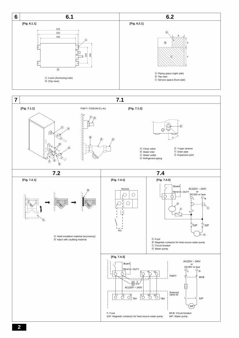
A Piping space (right side)B Top viewC Service space (front side)
B
a
b
cC
A
EB
CG
G
A
A
D
C
BEF
E
45°
[Fig. 7.1.1] [Fig. 7.1.2]PWFY- P200VM-E1-AU
A Close valveB Water inletC Water outletD Refrigerant piping
E Y-type strainerF Drain pipeG Expansion joint
A
B
A Heat insulation material (accessory)B Inject with caulking material
IN1
TB142ABoard
A
NL
52P52P
TB141A OUT1AC220V ~ 240V
DC30V or lessor
B
C
D
A FuzeB Magnetic contactor for heat source water pumpC Circuit breakerD Water pump
Board
TB141A OUT1
TB1 TB2
PWFY
WP
1 2 3 L N
L N
Solenoidvalve kit
F52P
AC220V ~ 240V
NL
52P
MCB
AC220V ~ 240V
DC30V or lessor
F: Fuze MCB: Circuit breaker52P: Magnetic contactor for heat source water pump WP: Water pump
WT05377X05.book Page 2 Friday, November 9, 2012 1:19 PM
3
8 8.1[Fig. 8.1.1]
9 9.1
9.2[Fig. 9.2.1]
9.3[Fig. 9.3.1] [Fig. 9.3.2]
D
A
B
C
E
480
100
191
54102
114
134
184 (206*1)
*1: PWFY-P100/200VM-E1-AU
A Refrigerant piping (gas) B Refrigerant piping (liquid)C Water inlet D Water outletE Drain outlet
A
A
E
C
F
B
D
[Fig. 9.1.1] [Fig. 9.1.2]
A Thermal insulationB Pull out insulationC Wrap with damp clothD Return to original positionE Ensure that there is no gap hereF Wrap with insulating tape
A Cut hereB Remove brazed cap
C C C
D 2
E
AB 1
A Downward slope 1/100 or moreB Drain hoseC UnitD Collective pipingE Maximize this length to approx. 10 cm
AC
B
A ScrewsB Front panelC Control box
C
AA
A
B
D
E
G
F
A To prevent external tensile force from applying to the wiring connection sec-tion of power source terminal block use buffer bushing like PG connection or the like.
B External signal input cableC External signal output cableD Power source wiringE Tensile forceF Use ordinary bushingG Transmission cable and MA remote controller cable
WT05377X05.book Page 3 Friday, November 9, 2012 1:19 PM
4
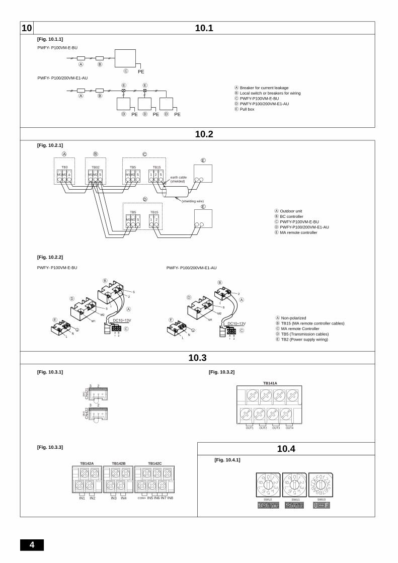
10 10.1[Fig. 10.1.1]
10.2[Fig. 10.2.1]
[Fig. 10.2.2]
10.3
[Fig. 10.3.3] 10.4[Fig. 10.4.1]
A B
A B
C
E E
PE
PEPED PED D
A Breaker for current leakageB Local switch or breakers for wiringC PWFY-P100VM-E-BUD PWFY-P100/200VM-E1-AUE Pull box
PWFY- P100VM-E-BU
PWFY- P100/200VM-E1-AU
TB02 TB15
earth cable (shielded)
TB5
SM1M2 SM1M2
TB3
M1M2
BA
1 2 S
CE
ETB15TB5
SM1M2 1 2
D (shielding wire)
A Outdoor unitB BC controllerC PWFY-P100VM-E-BUD PWFY-P100/200VM-E1-AUE MA remote controller
B
A
S
2
1
LN
DC10~13V
1 2A B
C
S
M2
M1
D
E
2
S
M2
M1
A
B
D
E
1
LN
DC10~13V
A B1 2
C
A Non-polarizedB TB15 (MA remote controller cables)C MA remote ControllerD TB5 (Transmission cables)E TB2 (Power supply wiring)
PWFY- P100VM-E-BU PWFY- P100/200VM-E1-AU
CN
421
(BK
)(B
U)
CN
422
3
2
2
3
OUT4OUT3OUT2
TB141A
OUT1
[Fig. 10.3.1] [Fig. 10.3.2]
IN1 IN2 IN3 IN4 IN5 IN6 IN7 IN8
TB142CTB142BTB142A
COM+ SWU2 SWU3SWU1
WT05377X05.book Page 4 Friday, November 9, 2012 1:19 PM
5
GB
Contents
1. Safety precautions .............................................................................................51.1. Before installation and electric work .................................................51.2. Precautions for devices that use R410A refrigerant .........................51.3. Before getting installed.....................................................................61.4. Before getting installed (moved) -electrical work..............................61.5. Before starting the test run ...............................................................6
2. About the product...............................................................................................63. Specifications.....................................................................................................74. Confirmation of parts attached...........................................................................75. Lifting method ....................................................................................................76. Installation of unit and service space .................................................................7
6.1. Installation ........................................................................................76.2. Service space...................................................................................7
7. Water pipe installation........................................................................................77.1. Precautions during installation .........................................................87.2. Insulation installation ........................................................................8
7.3. Water processing and water quality control .....................................87.4. Pump interlock..................................................................................9
8. Refrigerant pipe and drain pipe specifications...................................................98.1. Refrigerant pipe, drain pipe and filling port.......................................9
9. Connecting refrigerant pipes and drain pipes ....................................................99.1. Refrigerant piping work ....................................................................99.2. Drain piping work............................................................................109.3. Connecting electrical connections..................................................10
10. Electrical wiring ................................................................................................1010.1. Power supply wiring .......................................................................1110.2. Connecting remote controller, indoor and outdoor
11. Information on rating plate ...............................................................................12
1. Safety precautions
1.1. Before installation and electric work
Symbols used in the text
Warning:
Describes precautions that should be observed to prevent danger of injury ordeath to the user.
Caution:Describes precautions that should be observed to prevent damage to the unit.
Symbols used in the illustrations
Warning:• If the supply cord is damaged, it must be replaced by the manufacturer, its
service agent or similarly qualified persons in order to avoid a hazard.• This appliance is not intended for use by persons (including children) with
reduced physical, sensory or mental capabilities, or lack of experience andknowledge, unless they have been given supervision or instruction cocern-ing use of the appliance by a person responsible for their safety.
• Do not use refrigerant other than the type indicated in the manuals providedwith the unit and on the nameplate.- Doing so may cause the unit or pipes to burst, or result in explosion or fire during
use, during repair, or at the time of disposal of the unit.- It may also be in violation of applicable laws.- MITSUBISHI ELECTRIC CORPORATION cannot be held responsible for mal-
functions or accidents resulting from the use of the wrong type of refrigerant.• Do not use steel pipes as water pipes.
- Copper pipes are recommended.• The water circuit should be a closed circuit.• Ask the dealer or an authorized technician to install the air conditioner.
- Improper installation by the user may result in water leakage, electric shock, orfire.
• Install the unit in a place that can withstand its weight.- Inadequate strength may cause the unit to fall down, resulting in injuries.
• Do not touch the unit. The unit surface can be hot.• Do not install the unit where corrosive gas is generated.• Use the specified cables for wiring. Make the connections securely so that
the outside force of the cable is not applied to the terminals.- Inadequate connection and fastening may generate heat and cause a fire.
• Prepare for rain and other moisture and earthquakes and install the unit atthe specified place.- Improper installation may cause the unit to topple and result in injury.
• Always use an strainer and other accessories specified by Mitsubishi Elec-tric.
- Ask an authorized technician to install the accessories. Improper installation bythe user may result in water leakage, electric shock, or fire.
• Never repair the unit. If the air conditioner must be repaired, consult thedealer.- If the unit is repaired improperly, water leakage, electric shock, or fire may result.
• Do not touch the refrigerant pipes and Water pipes.- Improper handling may result in injury.
• When handling this product, always wear protective equipment.EG: Gloves, full arm protection namely boiler suit, and safety glasses.- Improper handling may result in injury.
• If refrigerant gas leaks during installation work, ventilate the room.- If the refrigerant gas comes into contact with a flame, poisonous gases will be
released.• Install the unit according to this Installation Manual.
- If the unit is installed improperly, water leakage, electric shock, or fire may result.• Have all electric work done by a licensed electrician according to “Electric
Facility Engineering Standard” and “Interior Wire Regulations” and theinstructions given in this manual and always use a special circuit.- If the power source capacity is inadequate or electric work is performed improp-
erly, electric shock and fire may result.• Keep the electric parts away from water (washing water etc.).
- It might result in electric shock, catching fire or smoke.• Securely install the heat source unit terminal cover (panel).
- If the terminal cover (panel) is not installed properly, dust or water may enter theheat source unit and fire or electric shock may result.
• When installing and moving the air conditioner to another site, do notcharge it with a refrigerant different from the refrigerant (R410A) specifiedon the unit.- If a different refrigerant or air is mixed with the original refrigerant, the refrigerant
cycle may malfunction and the unit may be damaged.• If the air conditioner is installed in a small room, measures must be taken to
prevent the refrigerant concentration from exceeding the safety limit even ifthe refrigerant should leak.- Consult the dealer regarding the appropriate measures to prevent the safety
limit from being exceeded. Should the refrigerant leak and cause the safety limitto be exceeded, hazards due to lack of oxygen in the room could result.
• When moving and reinstalling the air conditioner, consult the dealer or anauthorized technician.- If the air conditioner is installed improperly, water leakage, electric shock, or fire
may result.• After completing installation work, make sure that refrigerant gas is not
leaking.- If the refrigerant gas leaks and is exposed to a fan heater, stove, oven, or other
heat source, it may generate noxious gases.• Do not reconstruct or change the settings of the protection devices.
- If the pressure switch, thermal switch, or other protection device is shorted andoperated forcibly, or parts other than those specified by Mitsubishi Electric areused, fire or explosion may result.
• To dispose of this product, consult your dealer.• The installer and system specialist shall secure safety against leakage
according to local regulation or standards.- Following standards may be applicable if local regulation are not available.
• Pay a special attention to the place, such as a basement, etc. where refrig-eration gas can stay, since refrigeration is heavier than the air.
• Children should be supervised to ensure that they do not play with theappliance.
1.2. Precautions for devices that use R410A refrigerant
Warning:• Do not use refrigerant other than the type indicated in the manuals provided
with the unit and on the nameplate.- Doing so may cause the unit or pipes to burst, or result in explosion or fire during
use, during repair, or at the time of disposal of the unit.
Before installing the unit, make sure you read all the “Safety pre-cautions”.
The “Safety precautions” provide very important points regard-ing safety. Make sure you follow them.
: Indicates an action that must be avoided.
: Indicates that important instructions must be followed.
: Indicates a part which must be grounded.
: Beware of electric shock. (This symbol is displayed on the main unit label.)
<Color: yellow>
: Beware of hot surface.
Warning:
Carefully read the labels affixed to the main unit.
WT05377X05.book Page 5 Friday, November 9, 2012 1:19 PM
- It may also be in violation of applicable laws.- MITSUBISHI ELECTRIC CORPORATION cannot be held responsible for mal-
functions or accidents resulting from the use of the wrong type of refrigerant.
Caution:• Do not use the existing refrigerant piping.
- The old refrigerant and refrigerant oil in the existing piping contains a largeamount of chlorine which may cause the refrigerant oil of the new unit to deteri-orate.
- R410A is a high-pressure refrigerant and can cause the existing piping to burst.• Use refrigerant piping made of C1220 (CU-DHP) phosphorus deoxidized
copper as specified in the JIS H3300 “Copper and copper alloy seamlesspipes and tubes”. In addition, be sure that the inner and outer surfaces ofthe pipes are clean and free of hazardous sulphur, oxides, dust/dirt, shavingparticles, oils, moisture, or any other contaminant.- Contaminants on the inside of the refrigerant piping may cause the refrigerant
residual oil to deteriorate.• Store the piping to be used during installation indoors and keep both ends
of the piping sealed until just before brazing. (Store elbows and other jointsin a plastic bag.)- If dust, dirt, or water enters the refrigerant cycle, deterioration of the oil and com-
pressor trouble may result.• Use ester oil, ether oil or alkylbenzene (small amount) as the refrigerant oil
to coat flares and flange connections.- The refrigerant oil will degrade if it is mixed with a large amount of mineral oil.
• Use liquid refrigerant to fill the system.- If gas refrigerant is used to seal the system, the composition of the refrigerant in
the cylinder will change and performance may drop.• Do not use a refrigerant other than R410A.
- If another refrigerant (R22, etc.) is mixed with R410A, the chlorine in the refrig-erant may cause the refrigerant oil to deteriorate.
• Use a vacuum pump with a reverse flow check valve.- The vacuum pump oil may flow back into the refrigerant cycle and cause the
refrigerant oil to deteriorate.• Do not use the following tools that are used with conventional refrigerants.
(Gauge manifold, charge hose, gas leak detector, reverse flow check valve,refrigerant charge base, refrigerant recovery equipment)- If the conventional refrigerant and refrigerant oil are mixed in the R410A, the
refrigerant may deteriorated.- If water is mixed in the R410A, the refrigerant oil may deteriorate.- Since R410A does not contain any chlorine, gas leak detectors for conventional
refrigerants will not react to it.• Do not use a charging cylinder.
- Using a charging cylinder may cause the refrigerant to deteriorate.• Be especially careful when managing the tools.
- If dust, dirt, or water gets in the refrigerant cycle, the refrigerant may deteriorate.
1.3. Before getting installedCaution:
• Do not install the unit where combustible gas may leak.- If the gas leaks and accumulates around the unit, an explosion may result.
• Do not use the air conditioner where food, pets, plants, precision instru-ments, or artwork are kept.- The quality of the food, etc. may deteriorate.
• Do not use the air conditioner in special environments.- Oil, steam, sulfuric smoke, etc. can significantly reduce the performance of the
air conditioner or damage its parts.• When installing the unit in a hospital, communication station, or similar
place, provide sufficient protection against noise.- The inverter equipment, private power generator, high-frequency medical equip-
ment, or radio communication equipment may cause the air conditioner to oper-ate erroneously, or fail to operate. On the other hand, the air conditioner mayaffect such equipment by creating noise that disturbs medical treatment orimage broadcasting.
• Do not install the unit on a structure that may cause leakage.- When the room humidity exceeds 80 % or when the drain pipe is clogged, con-
densation may drip from the indoor unit. Perform collective drainage worktogether with the unit, as required.
1.4. Before getting installed (moved) - electri-cal work
Caution:• Ground the unit.
- Do not connect the ground wire to gas or water pipes, lightning rods, or tele-phone ground lines. Improper grounding may result in electric shock.
• Install the power cable so that tension is not applied to the cable.- Tension may cause the cable to break and generate heat and cause a fire.
• Install a leak circuit breaker, as required.- If a leak circuit breaker is not installed, electric shock may result.
• Use power line cables of sufficient current carrying capacity and rating.- Cables that are too small may leak, generate heat, and cause a fire.
• Use only a circuit breaker and fuse of the specified capacity.- A fuse or circuit breaker of a larger capacity or a steel or copper wire may result
in a general unit failure or fire.• Do not wash the air conditioner units.
- Washing them may cause an electric shock.• Be careful that the installation base is not damaged by long use.
- If the damage is left uncorrected, the unit may fall and cause personal injury orproperty damage.
• Install the drain piping according to this Installation Manual to ensureproper drainage. Wrap thermal insulation around the pipes to prevent con-densation.- Improper drain piping may cause water leakage and damage to furniture and
other possessions.• Be very careful about product transportation.
- Only one person should not carry the product if it weighs more than 20 kg.- Some products use PP bands for packaging. Do not use any PP bands for a
means of transportation. It is dangerous.- When transporting the unit, support it at the specified positions on the unit base.
Also support the unit at four points so that it cannot slip side ways.• Safely dispose of the packing materials.
- Packing materials, such as nails and other metal or wooden parts, may causestabs or other injuries.
- Tear apart and throw away plastic packaging bags so that children will not playwith them. If children play with a plastic bag which was not torn apart, they facethe risk of suffocation.
1.5. Before starting the test runCaution:
• Error code "7130" appears when both of the following conditions are met.- The PWFY unit is connected to the outdoor unit of Y series.- The version of the software is the one listed below.
PWFY series: earlier than Ver. 1.13Y(YHM) series: earlier than Ver. 12.27Y(YJM) series: earlier than Ver. 1.31Replace Y(YJM) series: earlier than Ver. 11.31HP(ZUBADAN) series: earlier than Ver. 22.27WY series: earlier than Ver. 12.29
• Turn on the power at least 12 hours before starting operation.- Starting operation immediately after turning on the main power switch can result
in severe damage to internal parts. Keep the power switch turned on during theoperational season.
• Do not touch the switches with wet fingers.- Touching a switch with wet fingers can cause electric shock.
• Do not touch the refrigerant pipes during and immediately after operation.- During and immediately after operation, the refrigerant pipes are may be hot
and may be cold, depending on the condition of the refrigerant flowing throughthe refrigerant piping, compressor, and other refrigerant cycle parts. Your handsmay suffer burns or frostbite if you touch the refrigerant pipes.
• Do not operate the air conditioner with the panels and guards removed.- Rotating, hot, or high-voltage parts can cause injuries.
• Do not turn off the power immediately after stopping operation.- Always wait at least five minutes before turning off the power. Otherwise, water
leakage and trouble may occur.• Do not touch the surface of the compressor during servicing.
- If unit is connected to the supply and not running, crank case heater at compres-sor is operating.
• Do not touch the panels near the fan exhaust outlet with bare hands: theycan get hot while the unit is in operation (even if it is stopped) or immedi-ately after operation and poses a risk of burns. Wear gloves to protect yourhands when it is necessary to touch the panels.
• While the unit is in operation or immediately after operation, high-tempera-ture exhaust air may blow out of the fan exhaust outlet. Do not hold yourhands over the outlet or touch the panels near the outlet.
• Be sure to provide a pathway for the exhaust air from the fan.• Water pipes can get very hot, depending on the preset temperature. Wrap
the water pipes with insulating materials to prevent burns.
2. About the product
Warning:• Do not use refrigerant other than the type indicated in the manuals provided
with the unit and on the nameplate.- Doing so may cause the unit or pipes to burst, or result in explosion or fire during
use, during repair, or at the time of disposal of the unit.- It may also be in violation of applicable laws.
- MITSUBISHI ELECTRIC CORPORATION cannot be held responsible for mal-functions or accidents resulting from the use of the wrong type of refrigerant.
• This unit uses R410A-type refrigerant.• Piping for systems using R410A may be different from that for systems using con-
ventional refrigerant because the design pressure in systems using R410A ishigher. Refer to Data Book for more information.
WT05377X05.book Page 6 Friday, November 9, 2012 1:19 PM
7
GB
• Some of the tools and equipment used for installation with systems that use othertypes of refrigerant cannot be used with the systems using R410A. Refer to DataBook for more information.
• Do not use the existing piping, as it contains chlorine, which is found in conven-tional refrigerating machine oil and refrigerant. This chlorine will deteriorate the
refrigerant machine oil in the new equipment. The existing piping must not beused as the design pressure in systems using R410A is higher than that in thesystems using other types of refrigerant and the existing pipes may burst.
3. Specifications
Warning:Do not use refrigerant other than the type indicated in the manuals provided with the unit and on the nameplate.
- Doing so may cause the unit or pipes to burst, or result in explosion or fire during use, during repair, or at the time of disposal of the unit.- It may also be in violation of applicable laws.- MITSUBISHI ELECTRIC CORPORATION cannot be held responsible for malfunctions or accidents resulting from the use of the wrong type of refrigerant.
4. Confirmation of parts attached
5. Lifting method
Caution:Be very careful when carrying the product.- Do not have only one person to carry product if it is more than 20 kg.- PP bands are used to pack some products. Do not use them as a mean for transportation because they are dangerous.- Tear plastic packaging bag and scrap it so that children cannot play with it. Otherwise plastic packaging bag may suffocate children to death.
6. Installation of unit and service space
6.1. Installation• Using the anchoring holes shown below, firmly bolt the unit to the base.
[Fig. 6.1.1] (P.2)
Bases• Be sure to install unit in a place strong enough to withstand its weight. If the base
is unstable, reinforce with a concrete base.• The unit must be anchored on a level surface. Use a level to check after installa-
tion.• If the unit is installed near a room where noise is a problem, using an anti-vibration
stand on the base of the unit is recommended.
Warning:• Be sure to install unit in a place strong enough to withstand its weight.
Any lack of strength may cause unit to fall down, resulting in a personalinjury.
• Have installation work in order to protect against earthquake.Any installation deficiency may cause unit to fall down, resulting in a per-sonal injury.
6.2. Service space• Please allow for the following service spaces after installation.
(All servicing can be performed from the front of the unit)
[Fig. 6.2.1] (P.2)
7. Water pipe installation• Before a long period of non use, purge the water out of the pipes and thoroughly
let them dry. • Use a closed water circuit. • When the unit is in cooling mode, add brine to the circulating water to prevent it
from freezing.• To use brine in the system, DipSW 1-10 must be set to ON. • When installed in a low-ambient temperature environment, keep the water circu-
lating at all times. If that is not possible, purge the water out of the pipes com-pletely or fill the water pipes with brine.
• Do not use the water used for this unit for drinking or food manufacturing.
• Do not use steel pipes as water pipes.
Model PWFY-P100VM-E-BU PWFY-P100VM-E1-AU PWFY-P200VM-E1-AU
Sound level 44dB<A> 29dB<A> 29dB<A>
Refrigerant R134a × 1.1 kg – –
Net weight 60 kg 35 kg 38 kg
Designpressure
R410A MPa 4.15 4.15 4.15
R134a MPa 3.60 – –
Water MPa 1.00 1.00 1.00
ConnectableOutdoor unit
Total capacity 50~100 % of outdoor unit capacity Connectable to only one outdoor unit 50~100 % of outdoor unit capacity
Model/QuantityR2, Replace R2 series,
WR2 series only
Y, Replace Y series,HP(ZUBADAN) series, WY series,
A Piping space (right side) B Top viewC Service space (front side)
Model Water inlet Water outlet
PWFY-P100VM-E-BU PT 3/4 Screw PT 3/4 Screw
PWFY-P100VM-E1-AU PT 3/4 Screw PT 3/4 Screw
PWFY-P200VM-E1-AU*1 When the attached
expansion joints are installed.
PT 1 Screw*1 PT 1 Screw*1
WT05377X05.book Page 7 Friday, November 9, 2012 1:19 PM
8
GB
7.1. Precautions during installation• Use the reverse-return method to insure proper pipe resistance to each unit.• To insure easy maintenance, inspection, and replacement of the unit, use a proper
joint, valve, etc. on the water intake and outlet port. In addition, be sure to install astrainer on the water intake pipe. (In order to maintain the unit, a strainer on thecirculating water inlet is necessary.)
• Install a suitable air vent on the water pipe. After sending water through the pipe,be sure to vent the excess air.
• Condensed water may form in the low-temperature sections of unit. Use a drain-age pipe connected to the drain valve at the base of the unit to drain the water.
• Install a back flow-prevention valve on the pump and a flexible joint to preventexcess vibration.
• Use a sleeve to protect the pipes where they go through a wall.• Use metal fittings to secure the pipes, and install them so that they have maximum
protection against breakage and bending.• Do not confuse the water intake and outlet valves.• This unit doesn’t have any heater to prevent freezing within tubes. When the water
flow is stopped on low ambient, take out the water from tubes.• The unused knockout holes should be closed and the opening of refrigerant pipes,
water pipes, power source and transmission wires should be filled with putty andso on to prevent from water.
• Install the strainer at the angle of 45˚ or less as shown in [Fig.7.1.2].• Wrap some sealing tape around the screw part to prevent water leakage. • Wrap the sealing tape as follows.
• Install the supplied strainer at the water inlet.• Hold the pipe on the unit side in place with a spanner when installing the pipes or
strainer. Tighten screws to a torque of 50 N·m. • Water pipes can get very hot, depending on the preset temperature. Wrap the
water pipes with insulating materials to prevent burns.
• On the PWFY-P200VM-E1-AU model, install the expansion joint (accessory) atthe inlet after installing the strainer, and outlet.
Example of unit installation (using water piping)
[Fig. 7.1.1] (P.2)
7.2. Insulation installationThe surface temperature of the water pipe would be very high, depending on the settemperature. Insulate the pipe to prevent burns. When operating PWFY-P100/P200VM-E1-AU with cold water, insulate the water pipe to prevent condensation. Wrap insulation material around water pipes as shown in [Fig. 7.2.1].• Any heat source piping.• Indoor piping in cold-weather regions where frozen pipes are a problem.• When air coming from the outside causes condensation to form on piping.• Any drainage piping.
[Fig. 7.2.1] (P.2)
7.3. Water processing and water quality con-trol
To preserve water quality, use the closed type water circuit. When the circulatingwater quality is poor, the water heat exchanger can develop scales, leading to areduction in heat-exchange power and possible corrosion of the heat exchanger.Please pay careful attention to water processing and water quality control wheninstalling the water circulation system.• Removal of foreign objects or impurities within the pipes.
During installation, be careful that foreign objects, such as welding fragments,sealant particles, or rust, do not enter the pipes.
• Water Quality Processing
1 Wrap the joint with sealing tape in the direction of the threads (clockwise), anddo not let the tape run over the edge.
2 Overlap the sealing tape by two-thirds to three-fourths of its width on eachturn. Press the tape with your fingers so that it is pressed firmly against eachthread.
3 Leave the 1.5th through 2nd farthest threads away from the pipe endunwrapped.
A Close valve B Water inletC Water outlet D Refrigerant pipingE Y-type strainer F Drain pipeG Expansion joint
A Heat insulation material (accessory)B Inject with caulking material
1 Depending on the quality of the water, the copper piping of the heat exchangermay become corroded. We recommend regular water quality processing.Water circulation systems using open heat storage tanks are particularlyprone to corrosion.When using an open-type heat storage tank, install a water-to-water heatexchanger, and use a closed-loop circuit on the air conditioner side. If a watersupply tank is installed, keep contact with air to a minimum, and keep the levelof dissolved oxygen in the water no higher than 1mg/ℓ.
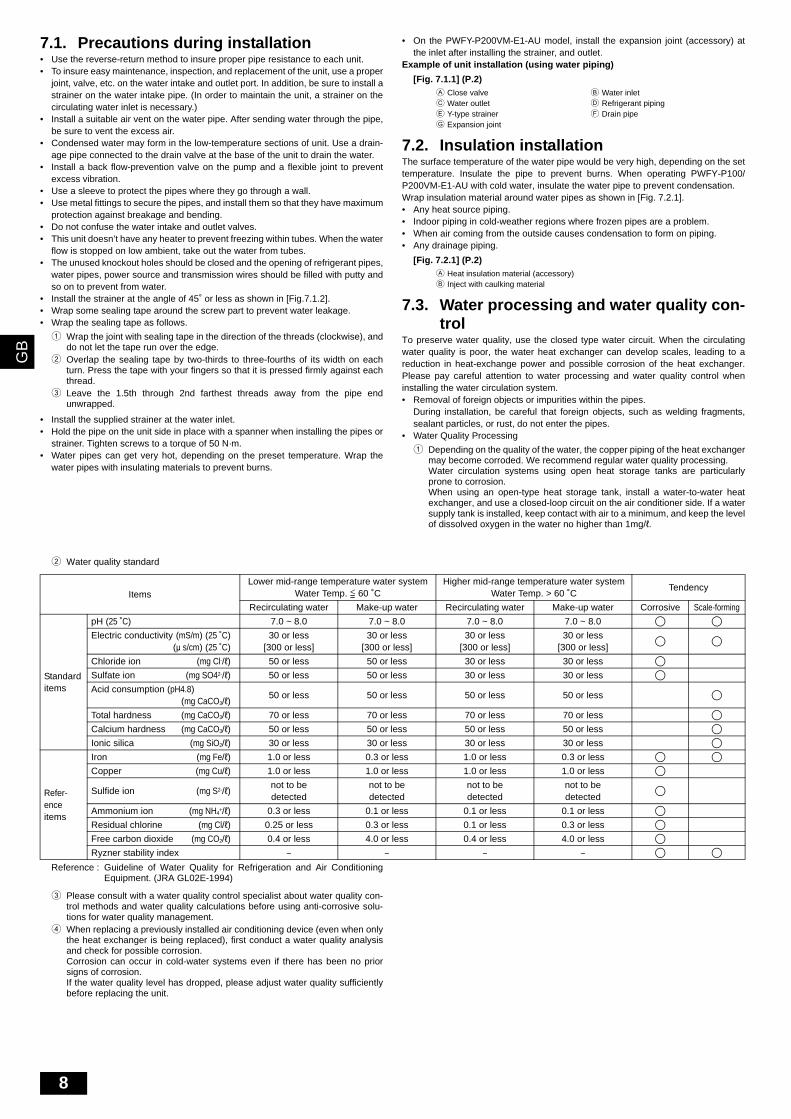
2 Water quality standard
Items
Lower mid-range temperature water systemWater Temp. 60 ˚C
Higher mid-range temperature water systemWater Temp. > 60 ˚C
Tendency
Recirculating water Make-up water Recirculating water Make-up water Corrosive Scale-forming
Electric conductivity (mS/m) (25 ˚C)(μ s/cm) (25 ˚C)
30 or less[300 or less]
30 or less[300 or less]
30 or less[300 or less]
30 or less[300 or less]
Chloride ion (mg Cl-/ℓ) 50 or less 50 or less 30 or less 30 or less
Sulfate ion (mg SO42-/ℓ) 50 or less 50 or less 30 or less 30 or less
Acid consumption (pH4.8)(mg CaCO3/ℓ)
50 or less 50 or less 50 or less 50 or less
Total hardness (mg CaCO3/ℓ) 70 or less 70 or less 70 or less 70 or less
Calcium hardness (mg CaCO3/ℓ) 50 or less 50 or less 50 or less 50 or less
Ionic silica (mg SiO2/ℓ) 30 or less 30 or less 30 or less 30 or less
Refer-ence items
Iron (mg Fe/ℓ) 1.0 or less 0.3 or less 1.0 or less 0.3 or less
Copper (mg Cu/ℓ) 1.0 or less 1.0 or less 1.0 or less 1.0 or less
Sulfide ion (mg S2-/ℓ)not to be detected
not to be detected
not to be detected
not to be detected
Ammonium ion (mg NH4+/ℓ) 0.3 or less 0.1 or less 0.1 or less 0.1 or less
Residual chlorine (mg Cl/ℓ) 0.25 or less 0.3 or less 0.1 or less 0.3 or less
Free carbon dioxide (mg CO2/ℓ) 0.4 or less 4.0 or less 0.4 or less 4.0 or less
Ryzner stability index – – – –
Reference : Guideline of Water Quality for Refrigeration and Air ConditioningEquipment. (JRA GL02E-1994)
3 Please consult with a water quality control specialist about water quality con-trol methods and water quality calculations before using anti-corrosive solu-tions for water quality management.
4 When replacing a previously installed air conditioning device (even when onlythe heat exchanger is being replaced), first conduct a water quality analysisand check for possible corrosion.Corrosion can occur in cold-water systems even if there has been no priorsigns of corrosion.If the water quality level has dropped, please adjust water quality sufficientlybefore replacing the unit.
WT05377X05.book Page 8 Friday, November 9, 2012 1:19 PM
9
GB
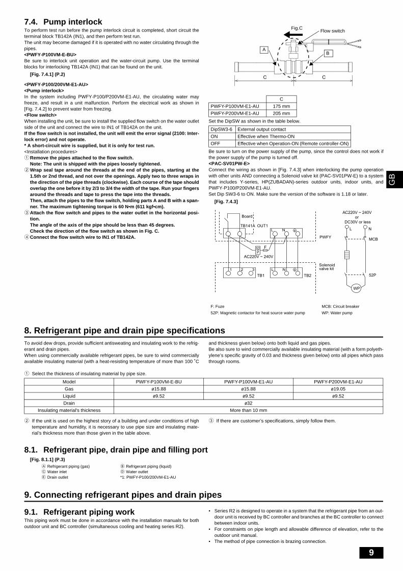
7.4. Pump interlockTo perform test run before the pump interlock circuit is completed, short circuit theterminal block TB142A (IN1), and then perform test run.The unit may become damaged if it is operated with no water circulating through thepipes.<PWFY-P100VM-E-BU>Be sure to interlock unit operation and the water-circuit pump. Use the terminalblocks for interlocking TB142A (IN1) that can be found on the unit.
[Fig. 7.4.1] (P.2)
<PWFY-P100/200VM-E1-AU><Pump interlock>In the system including PWFY-P100/P200VM-E1-AU, the circulating water mayfreeze, and result in a unit malfunction. Perform the electrical work as shown in[Fig. 7.4.2] to prevent water from freezing.<Flow switch>When installing the unit, be sure to install the supplied flow switch on the water outletside of the unit and connect the wire to IN1 of TB142A on the unit.If the flow switch is not installed, the unit will emit the error signal (2100: Inter-lock error) and not operate.* A short-circuit wire is supplied, but it is only for test run.<Installation procedures>1Remove the pipes attached to the flow switch.
Note: The unit is shipped with the pipes loosely tightened.2Wrap seal tape around the threads at the end of the pipes, starting at the
1.5th or 2nd thread, and not over the openings. Apply two to three wraps inthe direction of the pipe threads (clockwise). Each course of the tape shouldoverlap the one before it by 2/3 to 3/4 the width of the tape. Run your fingersaround the threads and tape to press the tape into the threads.Then, attach the pipes to the flow switch, holding parts A and B with a span-ner. The maximum tightening torque is 60 N•m (611 kgf•cm).
3Attach the flow switch and pipes to the water outlet in the horizontal posi-tion.The angle of the axis of the pipe should be less than 45 degrees.Check the direction of the flow switch as shown in Fig. C.
4Connect the flow switch wire to IN1 of TB142A.
Set the DipSW as shown in the table below.
Be sure to turn on the power supply of the pump, since the control does not work ifthe power supply of the pump is turned off. <PAC-SV01PW-E>Connect the wiring as shown in [Fig. 7.4.3] when interlocking the pump operationwith other units AND connecting a Solenoid valve kit (PAC-SV01PW-E) to a systemthat includes Y-series, HP(ZUBADAN)-series outdoor units, indoor units, andPWFY-P100/P200VM-E1-AU.Set Dip SW3-6 to ON. Make sure the version of the software is 1.18 or later.
[Fig. 7.4.3]
8. Refrigerant pipe and drain pipe specificationsTo avoid dew drops, provide sufficient antisweating and insulating work to the refrig-erant and drain pipes.When using commercially available refrigerant pipes, be sure to wind commerciallyavailable insulating material (with a heat-resisting temperature of more than 100 ˚C
and thickness given below) onto both liquid and gas pipes.Be also sure to wind commercially available insulating material (with a form polyeth-ylene’s specific gravity of 0.03 and thickness given below) onto all pipes which passthrough rooms.
1 Select the thickness of insulating material by pipe size.
2 If the unit is used on the highest story of a building and under conditions of hightemperature and humidity, it is necessary to use pipe size and insulating mate-rial’s thickness more than those given in the table above.
3 If there are customer’s specifications, simply follow them.
8.1. Refrigerant pipe, drain pipe and filling port[Fig. 8.1.1] (P.3)
9. Connecting refrigerant pipes and drain pipes
9.1. Refrigerant piping workThis piping work must be done in accordance with the installation manuals for bothoutdoor unit and BC controller (simultaneous cooling and heating series R2).
• Series R2 is designed to operate in a system that the refrigerant pipe from an out-door unit is received by BC controller and branches at the BC controller to connectbetween indoor units.
• For constraints on pipe length and allowable difference of elevation, refer to theoutdoor unit manual.
• The method of pipe connection is brazing connection.
C
PWFY-P100VM-E1-AU 175 mm
PWFY-P200VM-E1-AU 205 mm
DipSW3-6 External output contact
ON Effective when Thermo-ON
OFF Effective when Operation-ON (Remote controller-ON)
F: Fuze MCB: Circuit breaker
52P: Magnetic contactor for heat source water pump WP: Water pump
C C
A
Flow switchFig.C
B
Board
TB141A OUT1
TB1 TB2
PWFY
WP
1 2 3 L N
L N
Solenoidvalve kit
F52P
AC220V ~ 240V
NL
52P
MCB
AC220V ~ 240V
DC30V or lessor
Model PWFY-P100VM-E-BU PWFY-P100VM-E1-AU PWFY-P200VM-E1-AU
Gas ø15.88 ø15.88 ø19.05
Liquid ø9.52 ø9.52 ø9.52
Drain ø32
Insulating material's thickness More than 10 mm
A Refrigerant piping (gas) B Refrigerant piping (liquid)C Water inlet D Water outletE Drain outlet *1: PWFY-P100/200VM-E1-AU
WT05377X05.book Page 9 Friday, November 9, 2012 1:19 PM
10
GB
Caution:• Install the refrigerant piping for the indoor unit in accordance with the fol-
lowing.
1. Cut the tip of the indoor unit piping, remove the gas, and then remove the brazedcap.
[Fig. 9.1.1] (P.3)
2. Pull out the thermal insulation on the site refrigerant piping, braze the unit piping,and replace the insulation in its original position.Wrap the piping with insulating tape.
Note:• Pay strict attention when wrapping the copper piping since wrapping the
piping may cause condensation instead of preventing it.* Before brazing the refrigerant piping, always wrap the piping on the main body,
and the thermal insulation piping, with damp cloths to prevent heat shrink-age and burning the thermal insulation tubing. Take care to ensure that theflame does not come into contact with the main body itself.
[Fig. 9.1.2] (P.3)
Cautions On Refrigerant Piping Be sure to use non-oxidative brazing for brazing to ensure that no foreign
matter or moisture enter into the pipe. Be sure to apply refrigerating machine oil over the flare connection seating
surface and tighten the connection using a double spanner. Provide a metal brace to support the refrigerant pipe so that no load is
imparted to the indoor unit end pipe. This metal brace should be provided50 cm away from the indoor unit’s flare connection.
Warning:• Do not use refrigerant other than the type indicated in the manuals provided
with the unit and on the nameplate.- Doing so may cause the unit or pipes to burst, or result in explosion or fire during
use, during repair, or at the time of disposal of the unit.- It may also be in violation of applicable laws.- MITSUBISHI ELECTRIC CORPORATION cannot be held responsible for mal-
functions or accidents resulting from the use of the wrong type of refrigerant.• When installing and moving the unit, do not charge it with refrigerant other
than the refrigerant (R407C or R22) specified on the unit.- Mixing of a different refrigerant, air, etc. may cause the refrigerant cycle to mal-
function and result in severe damage.
Caution:• Use refrigerant piping made of C1220 (CU-DHP) phosphorus deoxidized
copper as specified in the JIS H3300 “Copper and copper alloy seamlesspipes and tubes”. In addition, be sure that the inner and outer surfaces ofthe pipes are clean and free of hazardous sulphur, oxides, dust/dirt, shavingparticles, oils, moisture, or any other contaminant.
• Never use existing refrigerant piping.- The large amount of chlorine in conventional refrigerant and refrigerator oil in
the existing piping will cause the new refrigerant to deteriorate.• Store the piping to be used during installation indoors and keep both ends
of the piping sealed until just before brazing.- If dust, dirt, or water gets into the refrigerant cycle, the oil will deteriorate and the
compressor may fail.
9.2. Drain piping work1. Ensure that the drain piping is downward (pitch of more than 1/100) to the outdoor
(discharge) side. Do not provide any trap or irregularity on the way. (1)2. Ensure that any cross-wise drain piping is less than 20 m (excluding the difference
of elevation). If the drain piping is long, provide metal braces to prevent it fromwaving. Never provide any air vent pipe. Otherwise drain may be ejected.
3. Use a hard vinyl chloride pipe VP-25 (with an external diameter of 32 mm) fordrain piping.
4. Ensure that collected pipes are 10 cm lower than the unit body’s drain port asshown in 2.
5. Do not provide any odor trap at the drain discharge port.6. Put the end of the drain piping in a position where no odor is generated.7. Do not put the end of the drain piping in any drain where ionic gases are gener-
ated.
[Fig. 9.2.1] (P. 3)
9.3. Connecting electrical connectionsVerify that the model name on the operating instructions on the cover of the controlbox is the same as the model name on the nameplate.
Step 1Remove the screws holding the terminal box cover in place.
[Fig. 9.3.1] (P. 3)
Note:Ensure that the wiring is not pinched when fitting the terminal box cover.Pinching the wiring may cut it.
Caution:Install wiring so that it is not tight and under tension. Wiring under tensionmay break, or overheat and burn.• Fix power source external input/output line wiring to control box by using buffer
bushing for tensile force to prevent electric shock. (PG connection or the like.)Connect transmission wiring to transmission terminal block through the knockouthole of control box using ordinary bushing.
• After wiring is complete, make sure again that there is no slack on the connec-tions, and attach the cover onto the control box in the reverse order removal.
[Fig. 9.3.2] (P. 3)
Caution:Wire the power supply so that no tension is imparted. Otherwise disconnec-tion, heating or fire result.
10. Electrical wiring
Precautions on electrical wiring
Warning:Electrical work should be done by qualified electrical engineers in accordancewith “Engineering Standards For Electrical Installation” and supplied installa-tion manuals. Special circuits should also be used. If the power circuit lackscapacity or has an installation failure, it may cause a risk of electric shock orfire.
1. Be sure to take power from the special branch circuit.2. Be sure to install an earth leakage breaker to the power.3. Install the unit to prevent that any of the control circuit cables (remote controller,
transmission cables, or external input/output line) is brought in direct contact withthe power cable outside the unit.
4. Ensure that there is no slack on all wire connections.5. Some cables (power, remote controller, transmission cables, or external input/out-
put line) above the ceiling may be bitten by mouses. Use as many metal pipes aspossible to insert the cables into them for protection.
6. Never connect the power cable to leads for the transmission cables. Otherwisethe cables would be broken.
7. Be sure to connect control cables to the indoor unit, remote controller, and the out-door unit.
8. Be sure to ground the unit.9. Select control cables from the conditions given in page 11.
Caution:Be sure to put the unit to the ground on the outdoor unit side. Do not connectthe earth cable to any gas pipe, water pipe, lightening rod, or telephone earthcable. Incomplete grounding may cause a risk of electric shock.
Types of control cables1. Wiring transmission cables• Types of transmission cables
Design wiring in accordance with the following table <Table 1>.• Be sure to use cables supplied with supplementary insulation.
A Cut hereB Remove brazed cap
A Thermal insulation B Pull out insulationC Wrap with damp cloth D Return to original positionE Ensure that there is no gap here F Wrap with insulating tape
A Downward slope 1/100 or moreB Drain hoseC UnitD Collective pipingE Maximize this length to approx. 10 cm
A Screws B Front panelC Control box
A To prevent external tensile force from applying to the wiring connection section of power source terminal block use buffer bushing like PG connection or the like.
B External signal input cableC External signal output cableD Power source wiringE Tensile forceF Use ordinary bushingG Transmission cable and MA remote controller cable
WT05377X05.book Page 10 Friday, November 9, 2012 1:19 PM
11
GB
1. Transmission cablesPWFY-P100VM-E-BU
PWFY-P100/200VM-E1-AU
10.1. Power supply wiring• Power supply cords of appliances shall not be lighter than design 245 IEC 57 or
227 IEC 57.• A switch with at least 3 mm contact separation in each pole shall be provided by
the Air conditioner installation.
ELECTRICAL WORK1. Electrical characteristics
2. Power cable specifications
[Fig. 10.1.1] (P. 4)
Caution:Do not use anything other than the correct capacity breaker and fuse. Usingfuse, wire or copper wire with too large capacity may cause a risk of malfunc-tion or fire.
10.2. Connecting remote controller, indoor and outdoor transmission cables
(Remote contoroller is optionally available.)• Connect unit TB5 and outdoor unit TB3. (Non-polarized 2-wire (shield))
The “S” on unit TB5 is a shielding wire connection. For specifications about theconnecting cables, refer to the outdoor unit installation manual.
• Install a remote controller following the manual supplied with the remote control-ler.
• Connect the “1” and “2” on unit TB15 to a MA remote controller. (Non-polarized2-wire)
[Fig. 10.2.1] (P.4) MA Remote controller• DC 10 to 13 V between 1 and 2 (MA remote controller)
[Fig. 10.2.2] (P.4) MA Remote controller• The MA remote controller cannot be used at the same time or interchangeably.
Note:Ensure that the wiring is not pinched when fitting the terminal box cover.Pinching the wiring may cut it.
Caution:• Use wire with supplemental insulation. • Input to TB142A, TB142B, and TB142C should not carry voltage.• Cables from equipment connected to external input/output should have supple-
mental insulation. • Use a single multiple-core cable for external input/output to allow for connection to
the PG screw.
Caution:Wire the power supply so that no tension is imparted. Otherwise disconnec-tion, heating or fire result.
10.3. External input/output functionPreset temperature input (external analog input: 4mA-20mA)External input is input through CN421, CN422 on the circuit board. (Fig. 10.3.1)Use the supplied connector. If no temperature settings are made via the MA remote controller, the temperaturechanges with the current. Refer to the instructions manual that came with the MA remote controller for how tomake the settings.4 mA → 10 °C 20 mA → 70 °CNote:Use a 4-20 mA signal output device with insulation.
Transmission cables MA Remote controller cables External input External output
Type of cableShielding wire (2-core)
CVVS, CPEVS or MVVSSheathed 2-core cable (shielded)
Remarks - Max.length: 200 m Max.length: 100 mRated voltage: L1-N: 220 ~ 240 V
Rated load: 0.6 A
*1 Connected with simple remote controller. CVVS, MVVS : PVC insulated PVC jacketed shielded control cableCVV, MVV : PVC insulated PVC sheathed control cableCPEVS : PE insulated PVC jacketed shielded communication cable
ModelPower supply Compressor RLA (A)
Hz Volts Voltage range MCA (A) Output (kW) SC (A) Heating
PWFY-P100VM-E-BU 50/60 220-230-240 VMax. 264 VMin. 198 V
15.71 1.0 1.25 11.63-11.12-10.66
ModelPower supply RLA (A)
Hz Volts Voltage range MCA (A) Cooling Heating
PWFY-P100VM-E1-AUPWFY-P200VM-E1-AU
50/60 220-230-240 VMax. 264 VMin. 198 V
0.085 0.068-0.065-0.063
ModelMinimum wire thickness (mm2)
Breaker for current leakageLocal swich (A)
Breaker for wiring (NFB) (A)Main cable branch Ground capacity fuse
PWFY-P100VM-E-BU 2.5 - 2.5 30 A 30 mA 0.1 sec or less 25 25 30
ModelMinimum wire thickness (mm2)
Breaker for current leakageLocal swich (A)
Breaker for wiring (NFB) (A)Main cable branch Ground capacity fuse
PWFY-P100VM-E1-AUPWFY-P200VM-E1-AU
Total operating current
16 A or less 1.5 1.5 1.5 20 A 30 mA 0.1 sec. or less 16 16 20
25 A or less 2.5 2.5 2.5 30 A 30 mA 0.1 sec. or less 25 25 30
32 A or less 4.0 4.0 4.0 40 A 30 mA 0.1 sec. or less 32 32 40
A Breaker for current leakageB Local switch or breakers for wiringC PWFY-P100VM-E-BUD PWFY-P100/200VM-E1-AUE Pull box
A Non-polarized B TB15 (MA remote controller cables)C MA remote Controller D TB5 (Transmission cables)E TB2 (Power supply wiring)
WT05377X05.book Page 11 Friday, November 9, 2012 1:19 PM
12
GB
External output terminalExternal output terminal (refer to Fig. 10.3.2) is ineffective when the circuit is open. Refer to Table 10.3.2 for information about each contact.The current and voltage in the circuit to be connected to external output terminal(TB141A OUT1) must meet the following conditions.
Table 10.3.2
External input terminalThe wire length must be within 100 m.External input terminal (refer to Fig. 10.3.3) is ineffective when the circuit is open. Refer to Table 10.3.3 through Table 10.3.5 for information about each contact.Only the “pump interlock” function is ineffective when the circuit is short-circuited.Connect a relay circuit to the external output terminal as shown in Fig. 7.4.1.The specifications of the relay circuit to be connected must meet the following condi-tions. Contact rating voltage DC15VContact rating current 0.1AMinimum applicable load 1mA at DC
Table 10.3.3<PWFY-P100VM-E-BU>TB142A
<PWFY-P100/200VM-E1-AU>TB142A
Table 10.3.4TB142B
Table 10.3.5TB142C
10.4. Setting addresses(Be sure to operate with the main power turned OFF.)
[Fig. 10.4.1] (P. 4)
• There are two types of rotary switch setting available: setting addresses 1 to 9 andover 10, and setting branch numbers.
• The rotary switches are all set to “0” when shipped from the factory. Theseswitches can be used to set unit addresses and branch numbers at will.
• The determination of indoor unit addresses varies with the system at site. Setthem referring to the DATA BOOK.
11. Information on rating plate
Warning:Do not use refrigerant other than the type indicated in the manuals provided with the unit and on the nameplate.
- Doing so may cause the unit or pipes to burst, or result in explosion or fire during use, during repair, or at the time of disposal of the unit.- It may also be in violation of applicable laws.- MITSUBISHI ELECTRIC CORPORATION cannot be held responsible for malfunctions or accidents resulting from the use of the wrong type of refrigerant.
Contact ratingcurrent
AC250V 1A or less
AC125V 3A or less
DC30V 3A or less
OUT1 Operation ON/OFF
OUT2 Defrost
OUT3 Compressor
OUT4 Error signal
Co
nta
ct ra
ting
volta
ge
IN1 Pump interlock
IN1 Flow switch
IN3 Connection demand
IN4 Operation ON/OFF
COM+ Common
IN5*1 Hot Water/Heating
IN6*2 Heating ECO
IN7*3 Anti-freeze
*1 PWFY-P100VM-E-BU Hot WaterPWFY-P100/200VM-E1-AU Heating
*2 Effective when SW 4-3 is set to ON.*3 Effective when SW 4-4 is set to ON.*4 When setting Heating ECO or Anti-Freeze mode, reset all power supply of all
units (outdoor/indoor units).
<Address board>
1 How to set addressesExample: If Address is “3”, remain SWU2 (for over 10) at “0”, and matchSWU1 (for 1 to 9) with “3”.
2 How to set branch numbers SWU3 (Series R2 only)Match the indoor unit’s refrigerant pipe with the BC controller’s end connectionnumber. Remain other than R2 at “0”.
Model PWFY-P100VM-E-BU PWFY-P100VM-E1-AU PWFY-P200VM-E1-AU
Refrigerant (kg) R134a 1.1 - -
Allowable pressure (MPa)
R410A 4.15 4.15 4.15
R134a 3.60 - -
water 1.0 1.0 1.0
Net weight (kg) 60 35 38
WT05377X05.book Page 12 Friday, November 9, 2012 1:19 PM
WT05377X05 Printed in Japan
This product is designed and intended for use in the residential, commercial and light-industrial environment.
The product at hand is based on the following EU regulations:
• Low Voltage Directive 2006/95/EC• Electromagnetic Compatibility Directive
2004/108/EC
Please be sure to put the contact address/telephone number on this manual before handing it to the customer.
HEAD OFFICE: TOKYO BLDG., 2-7-3, MARUNOUCHI, CHIYODA-KU, TOKYO 100-8310, JAPANAuthorized representative in EU:MITSUBISHI ELECTRIC EUROPE B.V.
HARMAN HOUSE, 1 GEORGE STREET, UXBRIDGE, MIDDLESEX UB8 1QQ, U.K.
WT05377X05.book Page 172 Friday, November 9, 2012 1:19 PM