Safety , Signal Words ........................................................................................................................................... 4Equipment Safety Guidelines ................................................................................................................................ 5Lighting and Marking ............................................................................................................................................. 5Safety Sign Locations ......................................................................................................................................... 6-8Safety Sign Care ................................................................................................................................................... 9Tire Safety ............................................................................................................................................................. 9Remember ............................................................................................................................................................ 9Before Operation .................................................................................................................................................. 10During Operation ................................................................................................................................................ 10-11Following Operation ............................................................................................................................................. 11Highway and Transport Operations ................................................................................................................... 11-12Performing Maintenance ...................................................................................................................................... 12Bolt Torque ........................................................................................................................................................... 13DT6085RA Auto Transport Front Half Parts Breakdown ..................................................................................... 14DT6085RA Auto Transport Back Half Parts Breakdown ..................................................................................... 15DT6085RA Auto Transport Parts List .................................................................................................................. 16Wheel Carrier Parts Breakdown & List and Disc Brake Parts Breakdown and List ............................................ 17Brake Cluster & Drum Parts Breakdown and Parts List ...................................................................................... 18Electrical Diagram & Brake Line Parts Breakdown and Parts List ...................................................................... 19Model 8659111 Brake Actuator Parts Breakdown and Parts List ........................................................................ 20Safety & Maintencance ........................................................................................................................................ 21Loading Instructions ............................................................................................................................................. 22Notes .................................................................................................................................................................... 23
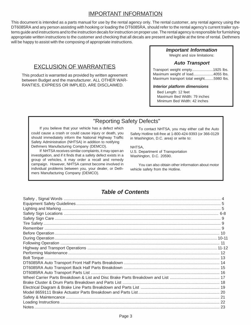
IMPORTANT INFORMATIONThis document is intended as a parts manual for use by the rental agency only. The rental customer, any rental agency using theDT6085RA and any person assisting with hooking or loading the DT6085RA, should refer to the rental agency's current trailer sys-tems guide and instructions and to the instruction decals for instruction on proper use. The rental agency is responsible for furnishingappropriate written instructions to the customer and checking that all decals are present and legible at the time of rental. Dethmerswill be happy to assist with the composing of appropriate instructions.
EXCLUSION OF WARRANTIESThis product is warranted as provided by written agreementbetween Budget and the manufacturer. ALL OTHER WAR-RANTIES, EXPRESS OR IMPLIED, ARE DISCLAIMED.
Transport weight empty.....................1925 lbs.Maximum weight of load....................4055 lbs.Maximum transport total weight.........5980 lbs.
Auto Transport
Interior platform dimensionsBed Length: 12 feetMaximum Bed Width: 79 inchesMinimum Bed Width: 42 inches
Important InformationWeight and size limitations:
Table of Contents
To contact NHTSA, you may either call the AutoSafety Hotline toll-free at 1-800-424-9393 (or 366-0129in Washington, D.C. area) or write to:
NHTSA,U.S. Department of TransportationWashington, D.C. 20590.
You can also obtain other information about motorvehicle safety from the Hotline.
If you believe that your vehicle has a defect whichcould cause a crash or could cause injury or death, youshould immediately inform the National Highway TrafficSafety Administration (NHTSA) in addition to notifyingDethmers Manufacturing Company (DEMCO).
If NHTSA receives similar complaints, it may open aninvestigation, and if it finds that a safety defect exists in agroup of vehicles, it may order a recall and remedycampaign. However, NHTSA cannot become involved inindividual problems between you, your dealer, or Deth-mers Manufacturing Company (DEMCO).
"Reporting Safety Defects"
Page 4
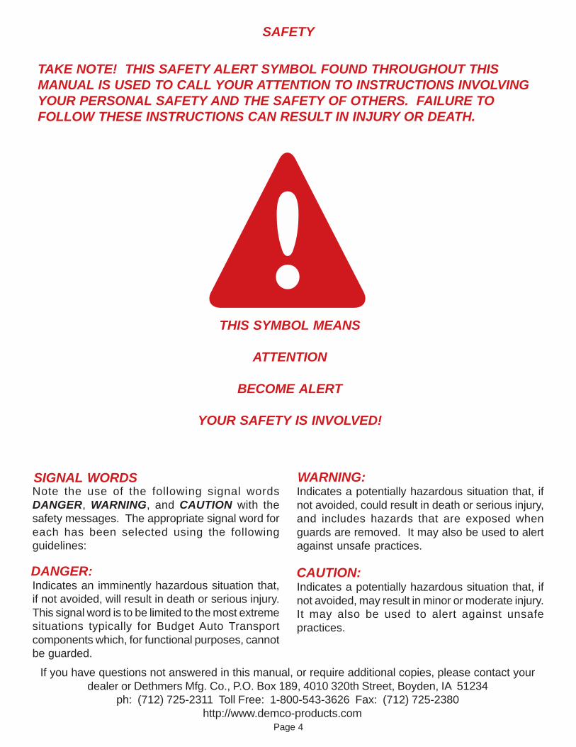
SAFETY
TAKE NOTE! THIS SAFETY ALERT SYMBOL FOUND THROUGHOUT THISMANUAL IS USED TO CALL YOUR ATTENTION TO INSTRUCTIONS INVOLVINGYOUR PERSONAL SAFETY AND THE SAFETY OF OTHERS. FAILURE TOFOLLOW THESE INSTRUCTIONS CAN RESULT IN INJURY OR DEATH.
THIS SYMBOL MEANS
ATTENTION
BECOME ALERT
YOUR SAFETY IS INVOLVED!
SIGNAL WORDSNote the use of the following signal wordsDANGER, WARNING, and CAUTION with thesafety messages. The appropriate signal word foreach has been selected using the followingguidelines:
DANGER:Indicates an imminently hazardous situation that,if not avoided, will result in death or serious injury.This signal word is to be limited to the most extremesituations typically for Budget Auto Transportcomponents which, for functional purposes, cannotbe guarded.
WARNING:Indicates a potentially hazardous situation that, ifnot avoided, could result in death or serious injury,and includes hazards that are exposed whenguards are removed. It may also be used to alertagainst unsafe practices.
CAUTION:Indicates a potentially hazardous situation that, ifnot avoided, may result in minor or moderate injury.It may also be used to alert against unsafepractices.
If you have questions not answered in this manual, or require additional copies, please contact yourdealer or Dethmers Mfg. Co., P.O. Box 189, 4010 320th Street, Boyden, IA 51234
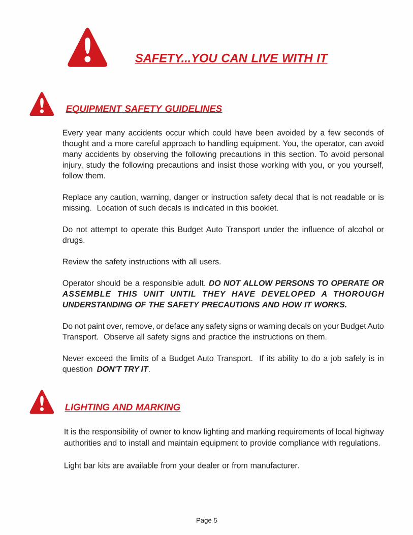
Every year many accidents occur which could have been avoided by a few seconds ofthought and a more careful approach to handling equipment. You, the operator, can avoidmany accidents by observing the following precautions in this section. To avoid personalinjury, study the following precautions and insist those working with you, or you yourself,follow them.
Replace any caution, warning, danger or instruction safety decal that is not readable or ismissing. Location of such decals is indicated in this booklet.
Do not attempt to operate this Budget Auto Transport under the influence of alcohol ordrugs.
Review the safety instructions with all users.
Operator should be a responsible adult. DO NOT ALLOW PERSONS TO OPERATE ORASSEMBLE THIS UNIT UNTIL THEY HAVE DEVELOPED A THOROUGHUNDERSTANDING OF THE SAFETY PRECAUTIONS AND HOW IT WORKS.
Do not paint over, remove, or deface any safety signs or warning decals on your Budget AutoTransport. Observe all safety signs and practice the instructions on them.
Never exceed the limits of a Budget Auto Transport. If its ability to do a job safely is inquestion DON'T TRY IT.
SAFETY...YOU CAN LIVE WITH IT
EQUIPMENT SAFETY GUIDELINES
LIGHTING AND MARKING
It is the responsibility of owner to know lighting and marking requirements of local highwayauthorities and to install and maintain equipment to provide compliance with regulations.
Light bar kits are available from your dealer or from manufacturer.
Page 6
IMPORTANTAfter securing trailer
to ball on truck,
PARKING JACK must
be cranked up until
stopped and left in
full up position for
road travel.
10/98 NR21021
CAUTIONActuator is springloaded. Use care whenservicing or injury mayoccur.
10/99 NP21010
A. Side of actuator NP21010 Qty. 1
B. Jack Tube NR21021 Qty. 1
SAFETY SIGN LOCATIONS
Types of safety sign and locations on Budget Auto Transport are shown in illustration below.Good safety requires that you familiarize yourself with various safety signs, type of warning,and particular function related to that area, that requires your SAFETY AWARENESS.
A
B
J
E
FG
H
I
C
BedLockdown
10/98 NR21011
C. Front of Bed NR21011 Qty. 1
D
Page 7
OPERATING INSTRUCTIONS
Read all instructions completely before use
1. Fully engage parking brake on towing vehicle. Secure ball coupler to a 2î- 6000 lb. rated ball on towingvehicle. Assure hitch and hitch ball are securely attached to towing vehicle, in good condition, not rusted,loose or stripped. Criss-cross safety chains under tongue and secure to mounting loops on towing vehicle.Secure emergency brake actuator cable to mounting loop on towing vehicle. Connect light wires to towingvehicle and check for proper operation. Raise tongue jack fully before moving car carrier.
2. Car carrier must be completely and properly attached to towing vehicle, setting on level surface, beforeloading towed vehicle. Car carrier is equipped with bed lockdown system. Release bed lockdown(s) and usingtilt bed jack, raise front of car carrier up until rear bumper touches ground, or jack is fully extended.
3. Pull tailgate lock pins on braces to unlock tailgate and slowly lower to ground.
4. With someone safely guiding you, center vehicle to car carrier and slowly drive forward until vehicle iscentered on center line indicator. Do not back vehicle onto car carrier. Place towed vehicle in park(automatic) or in gear (manual) and set parking brake.
5. Lower front of car carrier down with jack and secure bed lockdown(s). Single bed lockdown will lockautomatically. Visually check automatic lockdown.
6. Secure back of towed vehicle with safety chains located in floor boxes at rear of car carrier. Fasten chainssecurely to axle. Avoid chain contact with brake components. Secure chains snugly to eliminate slack.
7. Remove winch lock pins from chain winches at front of car carrier. Feed chain through opening in car carrierjust above winches and fasten securely to front frame or axle of towed vehicle. Chains must not attach to orgo over steering or brake parts of towed vehicle. Release parking brake and place towed vehicle in neutral.Tighten ratchet winches until front and rear chains are tight. Reinsert winch lock pins.
8. Place towed vehicle in park (automatic) or in gear (manual) and set parking brake.
9. Raise tailgate to transport position and lock in place with lock pins.
10. Release towing vehicleís parking brake and drive forward 100 feet. Stop and perform safety check. Checkhitch, hitch ball, ball coupler, safety chains, bolts, tailgate ramp, and other items to ensure that they are tightand in correct position. Check all lights to make sure they are operating properly. Repeat safety check afterfirst 5 miles and every 50 miles thereafter.
11.Unloading - Do not unhook car carrier from towing vehicle until towed vehicle is completelyunloaded from car carrier. Fully engage parking brake on towing vehicle. Reverse procedure in thisorder: step 7, step 6. Place towed vehicle in park or in gear, and set parking brake. Then proceed to steps 2,3, 4, and 5.
SAFETY
Perform safety check. Check hitch, hitch ball, ball coupler, safety chains, bolts, tailgate ramp, and other itemsto ensure they are tight and in correct position. Check all lights to make sure they are operating properly. Carcarrier tires must be inflated to recommended P.S.I. . See decal on car carrier for correct pressure. Tirepressure may increase during travel. Do not bleed off this increase in pressure. Repeat safety check after first5 miles and every 50 miles thereafter.
Do not exceed load capacity of car carrier. Car carriers may only be towed by approved vehicleswith correct towing capacity. Weight of loaded car carrier must not exceed weight of towing vehicle.Refer to towing vehicle ownerís manual for towing information. Do not exceed 45 M.P.H.
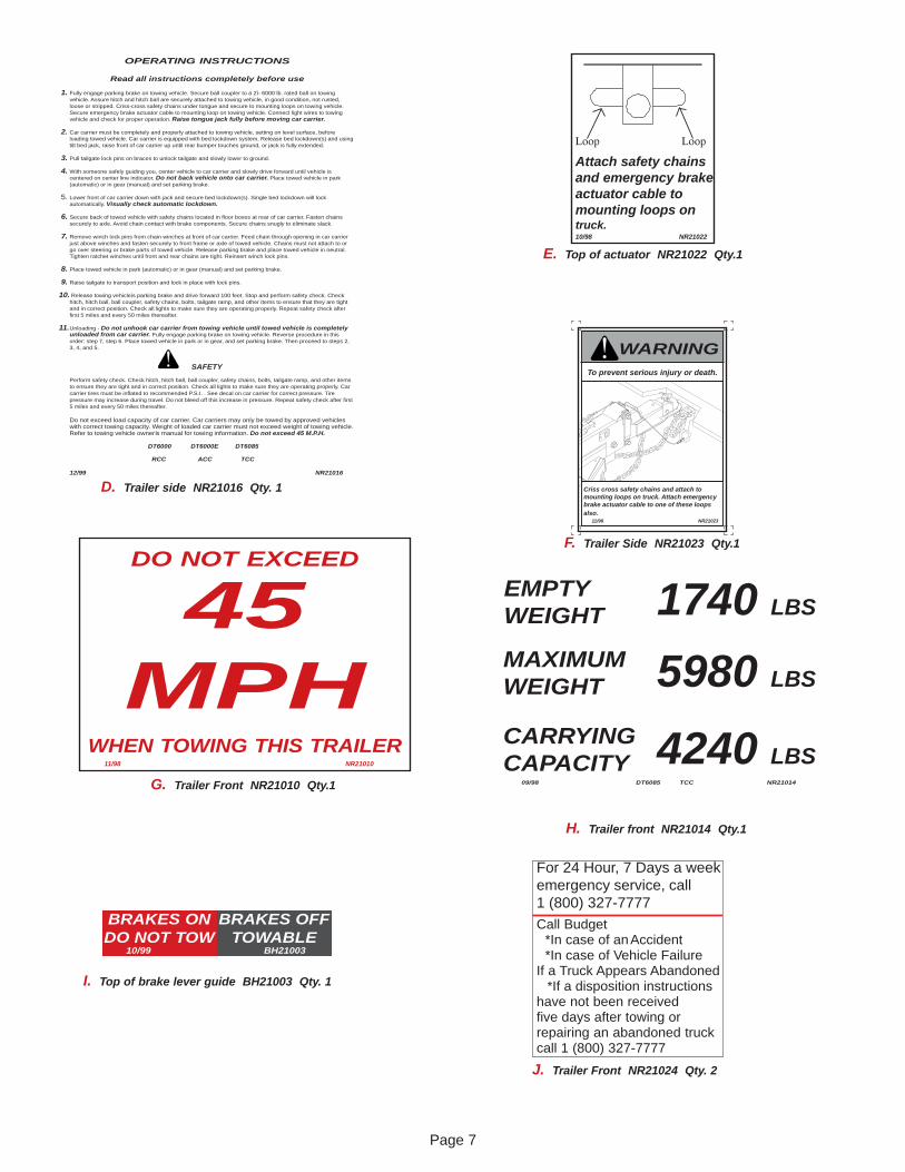
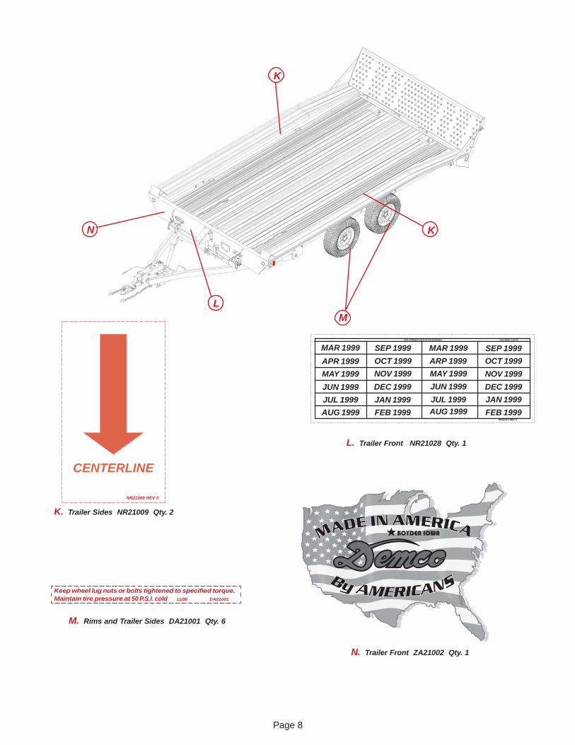
Criss cross safety chains and attach tomounting loops on truck. Attach emergencybrake actuator cable to one of these loopsalso. 11/98 NR21023
To prevent serious injury or death.
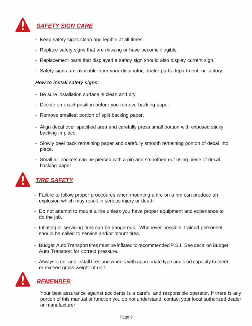
DO NOT EXCEED
45MPH
WHEN TOWING THIS TRAILER11/98 NR21010
J. Trailer Front NR21024 Qty. 2
E. Top of actuator NR21022 Qty.1
F. Trailer Side NR21023 Qty.1
G. Trailer Front NR21010 Qty.1
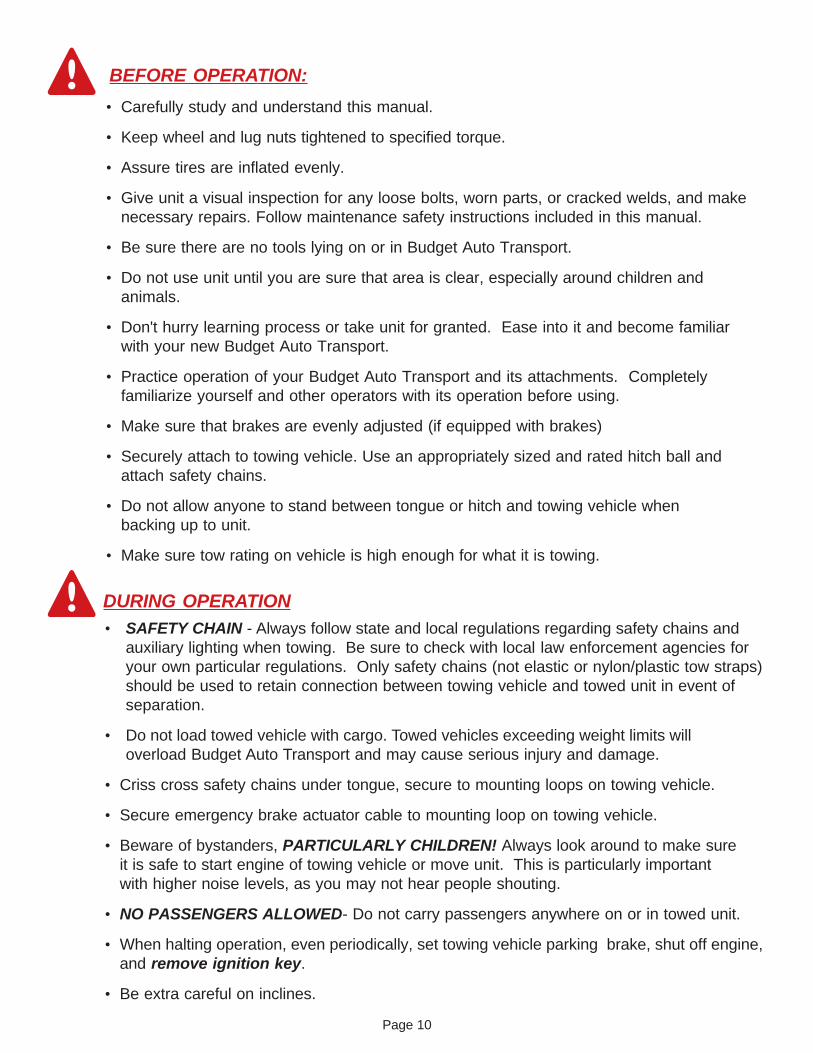
H. Trailer front NR21014 Qty.1
D. Trailer side NR21016 Qty. 1
For 24 Hour, 7 Days a weekemergency service, call1 (800) 327-7777
Call Budget *In case of an Accident *In case of Vehicle Failure
If a Truck Appears Abandoned *If a disposition instructions
have not been receivedfive days after towing orrepairing an abandoned truckcall 1 (800) 327-7777
BRAKES ONDO NOT TOW
BRAKES OFFTOWABLE
10/99 BH21003
I. Top of brake lever guide BH21003 Qty. 1
EMPTYWEIGHT
MAXIMUMWEIGHT
CARRYINGCAPACITY
1740 LBS
5980 LBS
4240 LBS09/98 DT6085 TCC NR21014
Page 8
Keep wheel lug nuts or bolts tightened to specified torque.Maintain tire pressure at 50 P.S.I. cold 11/98 DA21001
K. Trailer Sides NR21009 Qty. 2
L. Trailer Front NR21028 Qty. 1
M. Rims and Trailer Sides DA21001 Qty. 6
L
K
M
CENTERLINE
NR21009 REV 0
CAR CARRIER 6 MONTH PM REMINDER FM-235REV CS3-99
MAR 1999
APR 1999
MAY 1999
JUN 1999
JUL 1999
AUG 1999 FEB 1999
JAN 1999
DEC 1999
NOV 1999
OCT 1999
SEP 1999 MAR 1999
ARP 1999
MAY 1999
JUN 1999
JUL 1999AUG 1999
SEP 1999
OCT 1999
NOV 1999
DEC 1999
JAN 1999
FEB 1999NR21013 REV 0
N. Trailer Front ZA21002 Qty. 1
KN
Page 9
SAFETY SIGN CARE
� Keep safety signs clean and legible at all times.
� Replace safety signs that are missing or have become illegible.
� Replacement parts that displayed a safety sign should also display current sign.
� Safety signs are available from your distributor, dealer parts department, or factory.
How to install safety signs:
� Be sure installation surface is clean and dry.
� Decide on exact position before you remove backing paper.
� Remove smallest portion of split backing paper.
� Align decal over specified area and carefully press small portion with exposed stickybacking in place.
� Slowly peel back remaining paper and carefully smooth remaining portion of decal intoplace.
� Small air pockets can be pierced with a pin and smoothed out using piece of decalbacking paper.
TIRE SAFETY
� Failure to follow proper procedures when mounting a tire on a rim can produce anexplosion which may result in serious injury or death.
� Do not attempt to mount a tire unless you have proper equipment and experience todo the job.
� Inflating or servicing tires can be dangerous. Whenever possible, trained personnelshould be called to service and/or mount tires.
� Budget Auto Transport tires must be inflated to recommended P.S.I. See decal on BudgetAuto Transport for correct pressure.
� Always order and install tires and wheels with appropriate type and load capacity to meetor exceed gross weight of unit.
REMEMBER
Your best assurance against accidents is a careful and responsible operator. If there is anyportion of this manual or function you do not understand, contact your local authorized dealeror manufacturer.
Page 10
BEFORE OPERATION:
� Carefully study and understand this manual.
� Keep wheel and lug nuts tightened to specified torque.
� Assure tires are inflated evenly.
� Give unit a visual inspection for any loose bolts, worn parts, or cracked welds, and makenecessary repairs. Follow maintenance safety instructions included in this manual.
� Be sure there are no tools lying on or in Budget Auto Transport.
� Do not use unit until you are sure that area is clear, especially around children andanimals.
� Don't hurry learning process or take unit for granted. Ease into it and become familiarwith your new Budget Auto Transport.
� Practice operation of your Budget Auto Transport and its attachments. Completelyfamiliarize yourself and other operators with its operation before using.
� Make sure that brakes are evenly adjusted (if equipped with brakes)
� Securely attach to towing vehicle. Use an appropriately sized and rated hitch ball andattach safety chains.
� Do not allow anyone to stand between tongue or hitch and towing vehicle whenbacking up to unit.
� Make sure tow rating on vehicle is high enough for what it is towing.
DURING OPERATION� SAFETY CHAIN - Always follow state and local regulations regarding safety chains and
auxiliary lighting when towing. Be sure to check with local law enforcement agencies foryour own particular regulations. Only safety chains (not elastic or nylon/plastic tow straps)should be used to retain connection between towing vehicle and towed unit in event ofseparation.
� Do not load towed vehicle with cargo. Towed vehicles exceeding weight limits willoverload Budget Auto Transport and may cause serious injury and damage.
� Criss cross safety chains under tongue, secure to mounting loops on towing vehicle.
� Secure emergency brake actuator cable to mounting loop on towing vehicle.
� Beware of bystanders, PARTICULARLY CHILDREN! Always look around to make sureit is safe to start engine of towing vehicle or move unit. This is particularly importantwith higher noise levels, as you may not hear people shouting.
� NO PASSENGERS ALLOWED- Do not carry passengers anywhere on or in towed unit.
� When halting operation, even periodically, set towing vehicle parking brake, shut off engine,and remove ignition key.
� Be extra careful on inclines.
Page 11
� MANEUVER TOWING VEHICLE AT SAFE SPEEDS. DO NOT EXCEED 45 M.P.H.
� Avoid overhead wires or other obstacles. Contact with overhead lines could cause serious injuryor death.
� Avoid loose gravel, rocks, and holes; they can be dangerous for unit operation or movement.
� Allow for unit length when making turns.
� Do not work under raised components or attachments unless securely positioned and blocked.
� Keep all bystanders and pets clear of work area.
� Operate towing vehicle from operators seat only.
� As a precaution, recheck hardware on Budget Auto Transport every 50 miles, and correct allproblems. Follow maintenance safety procedures.
FOLLOWING OPERATION
� Following operation, or when unhitching, stop towing vehicle, set parking brake, shut offengine and remove ignition key.
� Store Budget Auto Transport in area away from human activity.
� Do not permit children to play on or around stored Budget Auto Transport.
� Make sure parked Budget Auto Transport is on hard, level surface.
� Wheel chocks may be needed to prevent unit from rolling.
� Adopt safe driving practices:
- Always drive at safe speed relative to local conditions and ensure that your speed is low enough for an emergency stop. Do no exceed 45 M.P.H.- Reduce speed prior to turns to avoid risk of overturning.
- Always keep towing vehicle in gear to provide engine braking when going downhill. Do not coast.
- Do not drink and drive!
� Comply with state and local laws governing highway safety.
� Local laws should be checked for all highway lighting and marking requirements.
HIGHWAY AND TRANSPORT OPERATIONS
Page 12
PERFORMING MAINTENANCE
� Good maintenance is your responsibility. Poor maintenance is an invitation to trouble.
� Make sure there is plenty of ventilation. Never operate engine of towing vehicle in a closedbuilding. Exhaust fumes may cause asphyxiation.
� Before working on Budget Auto Transport, stop towing vehicle, set parking brake, turn off engineand remove ignition key.
� Always block wheels and never use a jack as sole support.
� Always use proper tools or equipment for job at hand.
� Use extreme caution when making adjustments.
� Follow torque chart in this manual when tightening bolts and nuts.
� Openings in skin and minor cuts are susceptible to infection from brake fluid.Without immediate medical treatment, serious infection and reactions can occur.
� After servicing, be sure all tools, parts and service equipment are removed.
� Do not allow grease or oil to build up on any step or platform.
� When replacing bolts, refer to owners manual for proper size and grade.
� Refer to bolt torque chart for head identification marking.
� Where replacement parts are necessary for periodic maintenance and servicing, genuinefactory replacement parts must be used to restore your Budget Auto Transport to original specifications. Manufacturer will not claim responsibility for use of unapproved parts and/or accessories or other damages as a result of their use.
� If Budget Auto Transport has been altered in any way from original design, manufacturer doesnot accept any liability for injury or warranty.
� A fire extinguisher and first aid kit should be kept readily accessible while performingmaintenance on this Budget Auto Transport.
� Plan your route to avoid heavy traffic.
� Be a safe and courteous driver. Always yield to oncoming traffic in all situations, including narrowbridges, intersections, etc.
� Watch for obstructions overhead and to both sides while transporting.
� Operate with maximum visibility at all times. Make allowances for increased length and weightof Budget Auto Transport when making turns and stopping.
Page 13
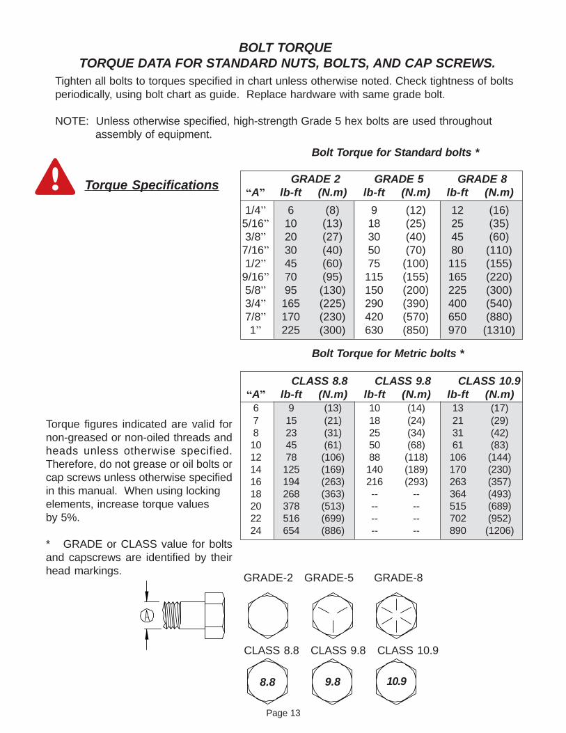
BOLT TORQUE TORQUE DATA FOR STANDARD NUTS, BOLTS, AND CAP SCREWS.
Tighten all bolts to torques specified in chart unless otherwise noted. Check tightness of boltsperiodically, using bolt chart as guide. Replace hardware with same grade bolt.
NOTE: Unless otherwise specified, high-strength Grade 5 hex bolts are used throughout assembly of equipment.
Torque figures indicated are valid fornon-greased or non-oiled threads andheads unless otherwise specified.Therefore, do not grease or oil bolts orcap screws unless otherwise specifiedin this manual. When using lockingelements, increase torque valuesby 5%.
* GRADE or CLASS value for boltsand capscrews are identified by theirhead markings.
Torque Specifications
CLASS 8.8 CLASS 9.8 CLASS 10.9�A� lb-ft (N.m) lb-ft (N.m) lb-ft (N.m)
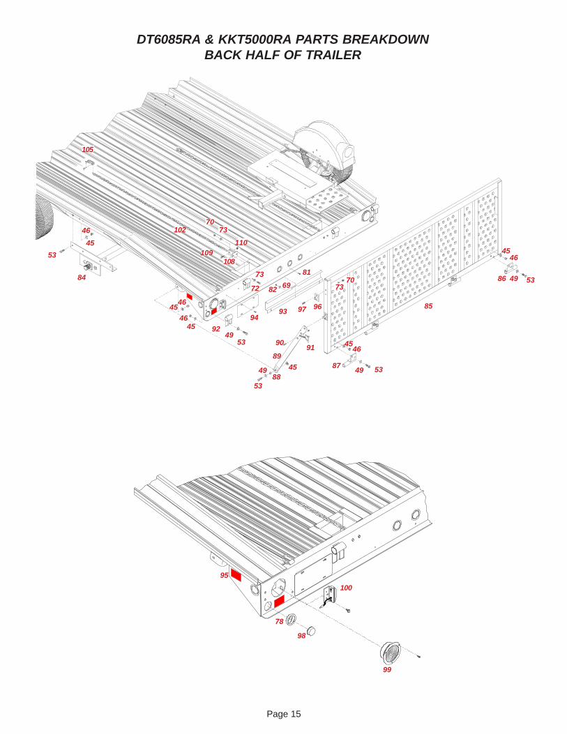
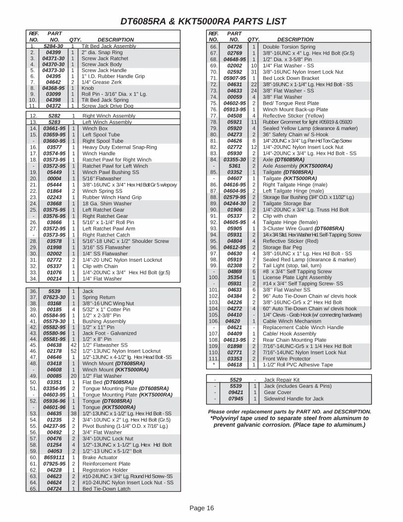
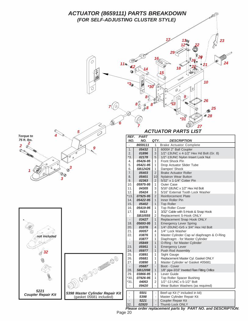
53. 04635 38 1/2"-13UNC x 1-1/2" Lg. Hex Hd Bolt - SS54. 01235 2 3/4"-10UNC x 2" Lg. Hex Hd Bolt (Gr.5)55. 04237-95 2 Pivot Bushing (1-1/4" O.D. x 7/16" Lg.)56. 00492 2 3/4" Flat Washer57. 00476 2 3/4"-10UNC Lock Nut58. 01254 4 1/2"-13UNC x 1-1/2" Lg. Hex Hd Bolt59. 04053 2 1/2�-13 UNC x 5-1/2� Bolt60. 8659111 1 Brake Actuator61. 07925-95 2 Reinforcement Plate62. 04228 1 Registration Holder63. 04623 2 #10-24UNC x 3/4" Lg. Round Hd Screw - SS64. 04624 2 #10-24UNC Nylon Insert Lock Nut - SS65. 04724 1 Bed Tie-Down Latch
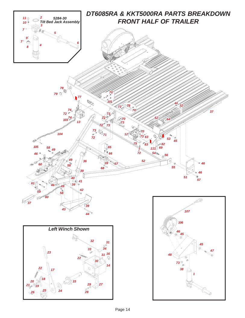
1. 5284-30 1 Tilt Bed Jack Assembly2. 04399 1 2" dia. Snap Ring3. 04371-30 1 Screw Jack Ratchet4. 04370-30 1 Screw Jack Body5. 04373-30 1 Screw Jack Handle6. 04395 1 1" I.D. Rubber Handle Grip7. 04642 2 1/4" Grease Zerk8. 04368-95 1 Knob9. 03099 1 Roll Pin - 3/16" Dia. x 1" Lg.10. 04398 1 Tilt Bed Jack Spring11. 04372 1 Screw Jack Drive Dog
12. 5282 1 Right Winch Assembly13. 5283 1 Left Winch Assembly14. 03661-95 1 Winch Box15. 03659-95 1 Left Spool Tube- 03660-95 1 Right Spool Tube
16. 03577 1 Heavy Duty External Snap-Ring17. 03574-95 1 Winch Handle18. 03573-95 1 Ratchet Pawl for Right Winch- 03572-95 1 Ratchet Pawl for Left Winch
19. 05449 1 Winch Pawl Bushing SS20. 00004 1 5/16� Flatwasher21. 05444 1 3/8"-16UNC x 3/4" Hex Hd Bolt Gr 5 w/epoxy22. 01864 2 Winch Spring SS23. 02243 1 Rubber Winch Hand Grip24. 03668 1 18 Ga. Shim Washer25. 03575-95 1 Left Ratchet Gear- 03576-95 1 Right Ratchet Gear
26. 03666 1 5/16" x 1-1/4" Roll Pin27. 03572-95 1 Left Ratchet Pawl Arm- 03573-95 1 Right Ratchet Catch
28. 03578 1 5/16"-18 UNC x 1/2" Shoulder Screw29. 01998 1 3/16" SS Flatwasher30. 02002 1 1/4" SS Flatwasher31. 02772 2 1/4"-20 UNC Nylon Insert Locknut32. 05337 1 Clip with Chain33. 01076 1 1/4"-20UNC x 3/4" Hex Hd Bolt (gr.5)34. 00214 1 1/4" Flat Washer
- 5529 - Jack Repair Kit- 5539 1 Jack (includes Gears & Pins)- 09421 1 Gear Cover- 07945 1 Sidewind Handle for Jack
Page 17
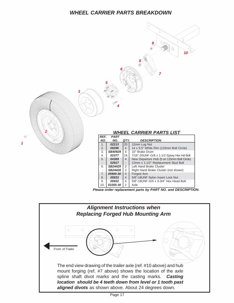
WHEEL CARRIER PARTS BREAKDOWN
Front of Trailer
REF. PARTNO. NO. QTY. DESCRIPTION
The end view drawing of the trailer axle (ref. #10 above) and hubmount forging (ref. #7 above) shows the location of the axlespline shaft divot marks and the casting marks. Castinglocation should be 4 teeth down from level or 1 tooth pastaligned divots as shown above. About 24 degrees down.
Alignment Instructions whenReplacing Forged Hub Mounting Arm
10
9
8
76
4
5
3
1 1. 02213 20 12mm Lug Nut2. 09296 4 14 x 5.5" White Rim (115mm Bolt Circle)3. SB40929 4 10" Brake Drum4. 02377 16 7/16"-20UNF Gr8 x 1-1/2 Epoxy Hex Hd Bolt5. 04369 4 New Departure Hub (5 on 115mm Bolt Circle)- 02917 - 12mm x 1-1/2" Replacement Stud Bolt6. SB24429 2 Left Hand Brake Cluster- SB24428 2 Right Hand Brake Cluster (not shown)7. 05900-30 4 Forged Arm8. 05933 4 5/8"-18UNF Nylon Insert Lock Nut9. 05932 4 5/8"-18UNF Gr5 x 3-3/4" Hex Head Bolt10. 03355-30 2 Axle
Please order replacement parts by PART NO. and DESCRIPTION.
WHEEL CARRIER PARTS LIST2
Page 18
44
55
7
16
22
116
17
3
118
6
3
12
9
15
10
10
1718
17
1817
14
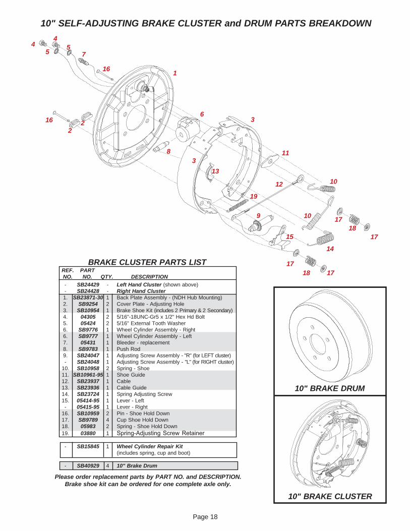
10" SELF-ADJUSTING BRAKE CLUSTER and DRUM PARTS BREAKDOWN
10" BRAKE CLUSTER
10" BRAKE DRUM
13
REF. PARTNO. NO. QTY. DESCRIPTION
Please order replacement parts by PART NO. and DESCRIPTION.Brake shoe kit can be ordered for one complete axle only.
28. SB12098 1 1/8" pipe-3/16" Inverted Flare Fitting Orifice29. 03866-95 1 Lever Guide*30. 07926-95 1 Top Roller Spacer Bushing*31. 04053 2 1/2�-13 UNC x 5-1/2� Bolt
- 09420 - Wear Button Washers (as required)
25
Torque to75 ft. lbs.
27
- 5501 - Beef-up Kit (* included in kit)- 5398 - Master Cylinder Repair Kit- 5221 - Coupler Repair Kit
32. 02920 - Thumb Lock ONLY
ACTUATOR (8659111) PARTS BREAKDOWN(FOR SELF-ADJUSTING CLUSTER STYLE)
5221Coupler Repair Kit
32
not included
*30
*31
*3
Please order replacement parts by PART NO. and DESCRIPTION.
Page 21
Safety is of utmost importance at all times. There are several items that should be checked each time before usingand while using the Trailer.
Make sure all bolts are properly tightened.
Make sure that the hitch and hitch ball are in good condition and not rusted, loose or stripped. Both the hitch andhitch ball must be securely attached to the truck. The ball coupler must latch securely around the ball and the safetyball clamp must be in position to lock the hitch on the ball.RECOMMENDED BALL HEIGHT: 20 inches to the top of the towing vehicle ball.
Criss-cross the safety chains under the car carrier tongue and secure to safety chain mounting loops on truck.
The snap hook on the actuator must be hooked to the rear bumper of the truck.
Check to make sure that all lights are in proper working order.
The Car Carrier tires should be inflated to the recommended 50 PSI.
The cable on the optional winch must be in good condition and should be stored neatly on winch when not in use.Any damaged or frayed cable must be replaced.
Periodically check all bolts and nuts to insure proper tension or torque.
Polyvinyl protective tape is required between all steel and aluminum surfaces which come in contact with each otherto prevent galvanic corrosion.
For safety reasons, loading or unloading of tow dollies should be done by two people.Tilting of the trailer is not requiredfor loading or unloading of tow dollies. Always use the winch when loading and unloading tow dollies.There are five po-sitions on the trailer for hauling tow dollies. The first position at the front of the trailer requires the tow dolly to be loadedrear first with the tongue facing to the rear of the trailer and resting on the bed. The rear four positions require the towdollies to be loaded facing forward and resting on top of the unit ahead of it.ALWAYS CENTER YOUR LOAD.
Example:When 1 unit is loaded, place it in the third position.When 2 units are loaded, place them in the second & third positions.When 3 units are loaded, place them in the middle three positions.When 4 units are loaded, place them in the first, second, fourth,and fifth positions.
Always tie down units with the chain binders provided.The binder side of the chain is always positioned towards the rearof the trailer at all five positions.
At the rear (5th) position, on the incline, there are two extra chains provided. Hook these into the rear position tie downhole of the 4th position and into the hole in the platform gusset on the main frame of the tow dolly. Hook the tie down intothe last hole provided and to the rear tie down d-ring.The flat iron in the tie down chain lays on the axle of the tow dolly.Be sure that all links are straight and hooks are pointedtowards the tie down holes when installing tie down chain binders.If a binder seems loose in the locked position, twist thelong chain end one complete revolution and lock down.Remember, safety first, this is a two person operation, the winch should always be used at all times.
Tow Dolly Loading Instructions
WARNING . THE DEALER/DISTRIBUTOR MUST REVIEW ALL OF THE FOLLOWING INSTRUCTIONSWITH THE CUSTOMER BEFORE ALLOWING USE OF THE ALUMINUM RENTAL TRAILER. FAILURE TOFOLLOW THESE INSTRUCTIONS, OR FAILURE TO INFORM THE CUSTOMER OF THESE INSTRUC-TIONS, CAN RESULT IN LOSS OF TOWING VEHICLE CONTROL, SEPARATION OF THE TRAILER FROMTHE TOWING VEHICLE, OR SEPARATION OF THE LOAD FROM THE TRAILER, CAUSING SEVERE PER-SONAL INJURY, DEATH, OR PROPERTY DAMAGE.
SAFETY & MAINTENANCE
Page 22
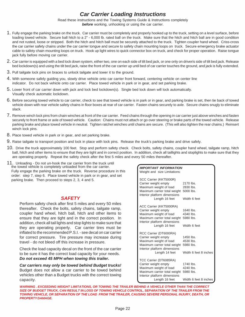
IMPORTANT INFORMATIONWeight and size Limitations:
SCC Carrier (KKT5000R)Carrier weight empty 2170 lbs.Maximum weight of load 2830 lbs.Maximum carrier total weight 5000 lbs.Interior platform dimensions
Length 16 feet Width 6 feet
ACC Carrier (KKT5000RA)Carrier weight empty 1640 lbs.Maximum weight of load 4340 lbs.Maximum carrier total weight 5980 lbs.Interior platform dimensions
Length 16 feet Width 6 feet
RCC Carrier (DT6000RA)Carrier weight empty 1450 lbs.Maximum weight of load 4530 lbs.Maximum carrier total weight 5980 lbs.Interior platform dimensions
Length 14 feet Width 6 feet 8 inches
TCC Carrier (DT6085RA)Carrier weight empty 1740 lbs.Maximum weight of load 4240 lbs.Maximum carrier total weight 5980 lbs.Interior platform dimensions
Length 16 feet Width 6 feet 8 inches
SAFETYPerform safety check after first 5 miles and every 50 milesthereafter. Check the bolts, safety chains, tailgate ramp,coupler hand wheel, hitch ball, hitch and other items toensure that they are tight and in the correct position. Inaddition, check all tail lights and stop lights to make sure thatthey are operating properly. Car carrier tires must beinflated to the recommended P.S.I. - see decal on car carrierfor correct pressure. Tire pressure may increase duringtravel - do not bleed off this increase in pressure.
Check the load capacity decal on the front of the car carrierto be sure it has the correct load capacity for your needs.Do not exceed 45 MPH when towing this trailer.
Car carriers may only be towed behind Budget trucks!Budget does not allow a car carrier to be towed behindvehicles other than a Budget trucks with the correct towingcapacity.
WARNING . EXCEEDING WEIGHT LIMITATIONS, OR TOWING THE TRAILER BEHIND A VEHICLE OTHER THAN THE CORRECTSIZE OF BUDGET TRUCK, CAN RESULT IN LOSS OF TOWING VEHICLE CONTROL, SEPARATION OF THE TRAILER FROM THETOWING VEHICLE, OR SEPARATION OF THE LOAD FROM THE TRAILER, CAUSING SEVERE PERSONAL INJURY, DEATH, ORPROPERTY DAMAGE.
the towed vehicle is completely unloaded from the car carrier.Fully engage the parking brake on the truck. Reverse procedure in thisorder: step 7, step 6. Place towed vehicle in park or in gear, and setparking brake. Then proceed to steps 2, 3, 4 and 5.
Car Carrier Loading InstructionsRead these instructions and the Towing Systems Guide & Instructions completely
before working, unhooking or using the car carrier.
1. Fully engage the parking brake on the truck. Car carrier must be completely and properly hooked up to the truck, setting on a level surface, beforeloading towed vehicle. Secure ball hitch to a 2" - 6,000 lb. rated ball on the truck. Make sure that the hitch and hitch ball are in good conditionand not rusted, loose or stripped. Both the hitch and hitch ball must be securely attached to the truck. Tighten coupler hand wheel. Criss-crossthe car carrier safety chains under the car carrier tongue and secure to safety chain mounting loops on truck. Secure emergency brake actuatorcable to safety chain mounting loops on truck. Hook up light wires to quick connector box on truck, and check for proper operation. Raise tonguejack fully before moving car carrier.
2. Car carrier is equipped with a bed lock down system, either two, one on each side of tilt bed jack, or one only on driverís side of tilt bed jack. Releasebed lockdown(s) and using the tilt bed jack, raise the front of the car carrier up until bed of car carrier touches the ground, and jack is fully extended.
3. Pull tailgate lock pins on braces to unlock tailgate and lower it to the ground.
4. With someone safely guiding you, slowly drive vehicle onto car carrier front forward, centering vehicle on center lineindicator. Do not back vehicle onto car carrier. Place towed vehicle in park or in gear, and set parking brake.
5. Lower front of car carrier down with jack and lock bed lockdown(s). Single bed lock down will lock automatically.Visually check automatic lockdown.
6. Before securing towed vehicle to car carrier, check to see that towed vehicle is in park or in gear, and parking brake is set, then tie back of towedvehicle down with rear vehicle safety chains in floor boxes at rear of car carrier. Fasten chains securely to axle. Secure chains snugly to eliminateslack.
7. Remove winch lock pins from chain winches at front of the car carrier. Feed chains through the opening in car carrier just above winches and fastensecurely to front frame or axle of towed vehicle. Caution: Chains must not attach or go over steering or brake parts of the towed vehicle. Releaseparking brake and place towed vehicle in neutral. Tighten ratchet winches until chains are secure. (This will also tighten the rear chains.) Reinsertwinch lock pins.
8. Place towed vehicle in park or in gear, and set parking brake.
9. Raise tailgate to transport position and lock in place with lock pins. Release the truck's parking brake and drive safely.
10. Drive the truck approximately 100 feet. Stop and perform safety check. Check bolts, safety chains, coupler hand wheel, tailgate ramp, hitchball, hitch and other items to ensure that they are tight and in correct position. In addition, check all taillights and stoplights to make sure that theyare operating properly. Repeat the safety check after the first 5 miles and every 50 miles thereafter.
11. Unloading - Do not un-hook the car carrier from the truck until