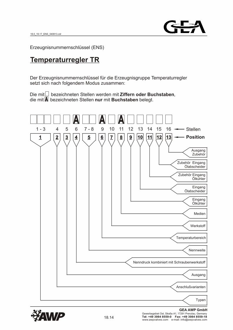
Page 1
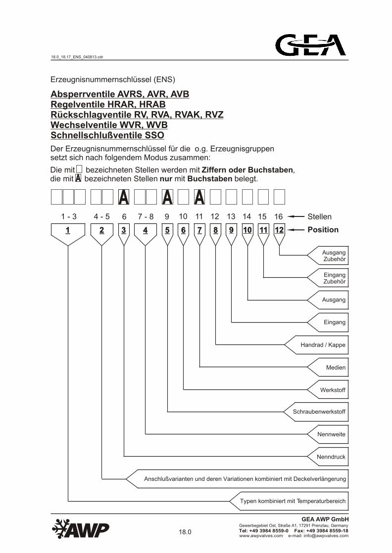
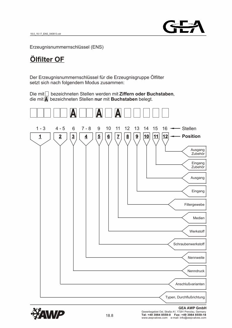
Erzeugnisnummernschlüssel (ENS)
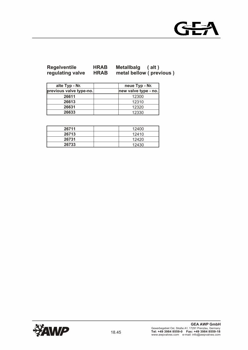
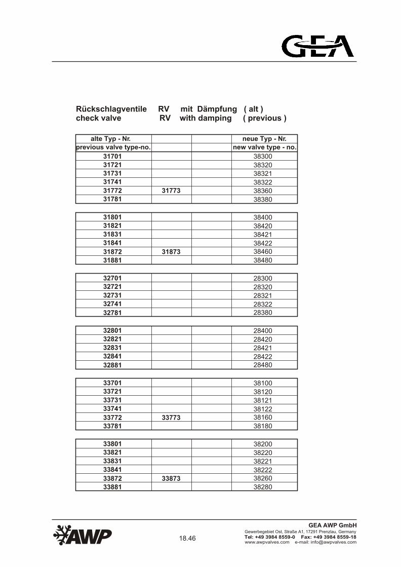
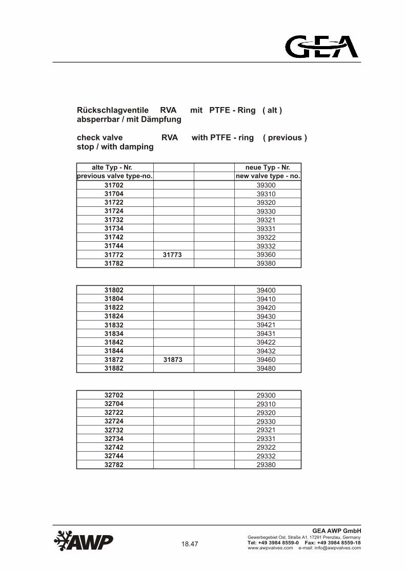
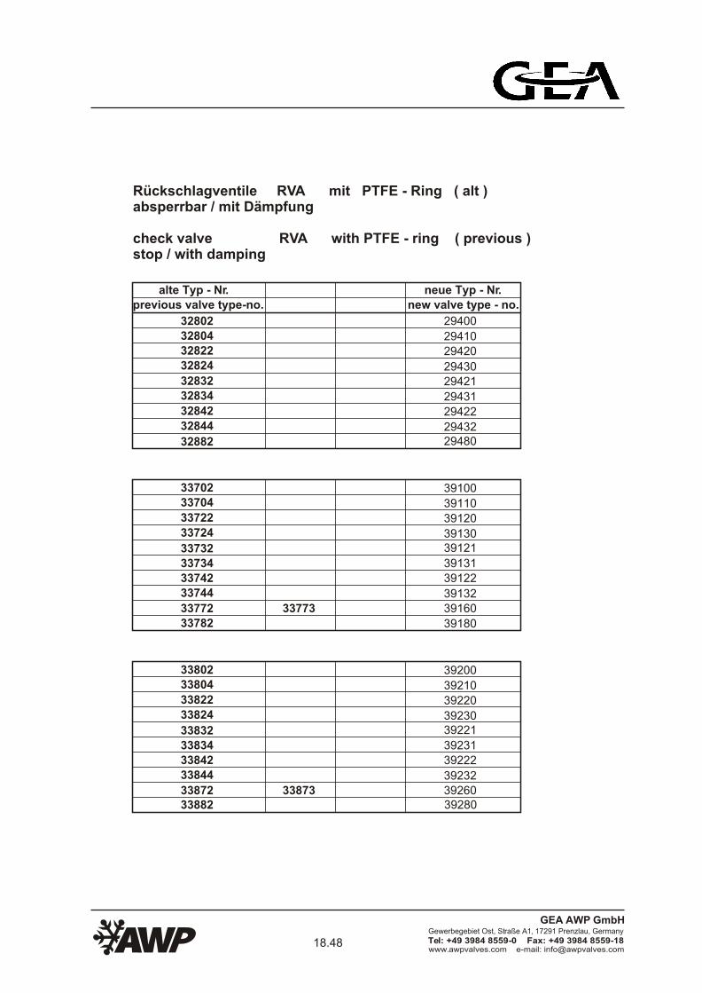
Absperrventile AVRS, AVR, AVBRegelventile HRAR, HRABRückschlagventile RV, RVA, RVAK, RVZWechselventile WVR, WVBSchnellschlußventile SSO
Der Erzeugnisnummernschlüssel für die o.g. Erzeugnisgruppen setzt sich nach folgendem Modus zusammen:
Die mit bezeichneten Stellen werden mit Ziffern oder Buchstaben, die mit bezeichneten Stellen nur mit Buchstaben belegt.
AA AAAAAA
Stellen
Position
1 - 3 7 - 86 11109 1312 14 15 16
11 22 554433 66 8877 99 1010 1111 1212
AusgangZubehör
EingangZubehör
Ausgang
Eingang
Handrad / Kappe
Medien
Werkstoff
Schraubenwerkstoff
Nennweite
Nenndruck
Anschlußvarianten und deren Variationen kombiniert mit Deckelverlängerung
Typen kombiniert mit Temperaturbereich
4 - 5
18.0_18.17_ENS_040813.cdr
18.0www.awpvalves.com e-mail: [email protected]
Gewerbegebiet Ost, Straße A1, 17291 Prenzlau, Germany
Tel: +49 3984 8559-0 Fax: +49 3984 8559-18
GEA AWP GmbH
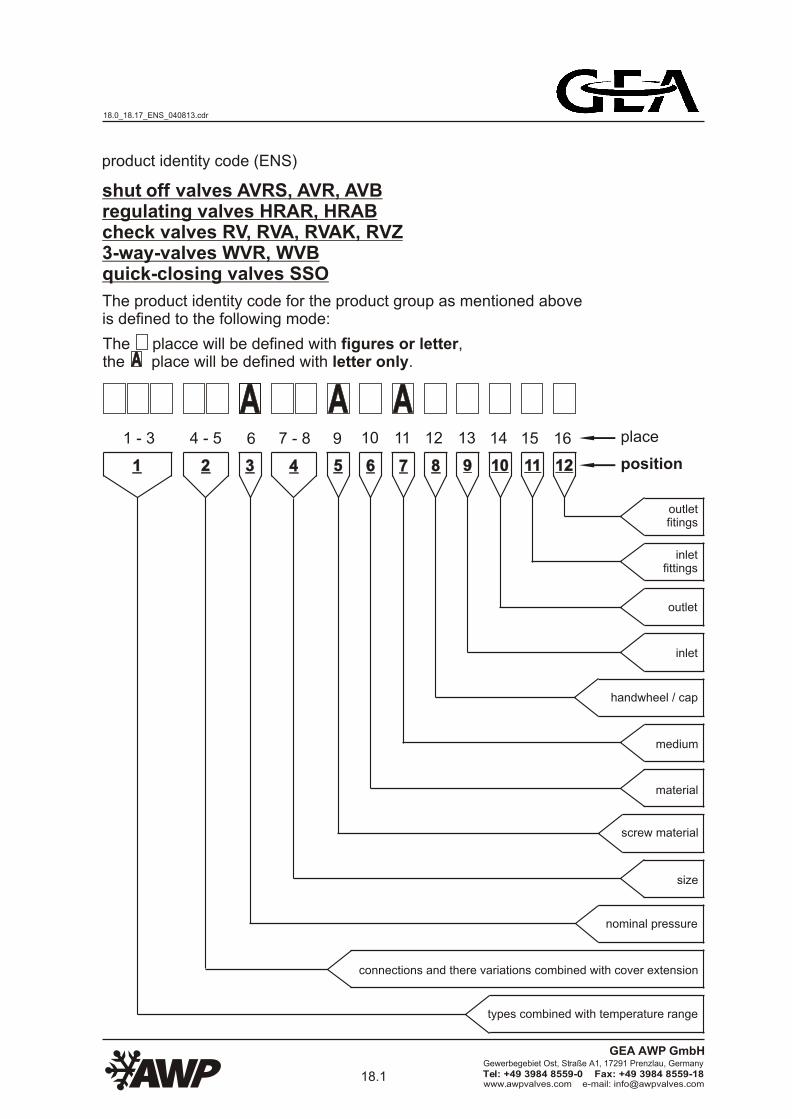
Page 2
AA AAAA1 - 3 6 11109 1312 14 15 16
11 22 554433 66 8877 99 1010 1111 1212
shut off valves AVRS, AVR, AVBregulating valves HRAR, HRABcheck valves RV, RVA, RVAK, RVZ3-way-valves WVR, WVBquick-closing valves SSO
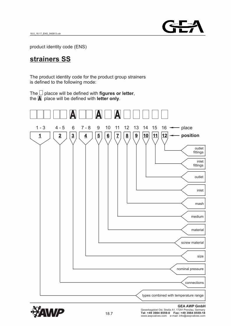
product identity code (ENS)
The product identity code for the product group as mentioned above is defined to the following mode:
The placce will be defined with figures or letter,the place will be defined with letter only.AA
place
position
outletfitings
inletfittings
outlet
inlet
handwheel / cap
medium
material
screw material
size
nominal pressure
connections and there variations combined with cover extension
types combined with temperature range
7 - 84 - 5
18.0_18.17_ENS_040813.cdr
18.1www.awpvalves.com e-mail: [email protected]
Gewerbegebiet Ost, Straße A1, 17291 Prenzlau, Germany
Tel: +49 3984 8559-0 Fax: +49 3984 8559-18
GEA AWP GmbH
Page 3
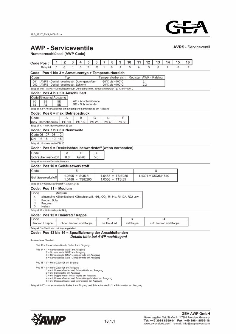
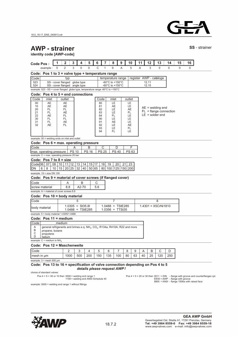
AWP - ServiceventileNummernschlüssel [AWP-Code]
1 2 3 4 5 6 7 8 9 10 11 12 13 14 15 16
0 6 1 6 2 C 1 0 A 5 A 3 0 2 0 2Beispiel :
Code: Pos 1 bis 3 = Armaturentyp + Temperaturbereich
Code Typ Temperaturbereich Register AWP - Katalog
061062
AVRS - Deckel geschraubt DurchgangsformAVRS - Deckel geschraubt Eckform
-20°C bis +100°C-20°C bis +100°C
2.12.2
Code: Pos 4 bis 5 = AnschlußartCode
6062
Code Pos :
AVRS - Serviceventil
Beispiel: 061 - AVRS = Deckel geschraubt Durchgangsform, Temperaturbereich -20°C bis +100°C
Eingang
SEAE
Ausgang
SESE
AE = AnschweißendeSE = Schraubende
Beispiel: 62 = Anschweißende am Eingang und Schraubende am Ausgang
Code: Pos 6 = max. BetriebsdruckCode
max. Betriebsdruck
A B C D F
PS 10 PS 16 PS 25 PS 40 PS 63Beispiel: C = max. Betriebsdruck 25 bar
Code: Pos 7 bis 8 = NennweiteCode
DN
06 07 08 10
6 8 10 15
Beispiel: 10 = Nennweite DN 15
Code: Pos 9 = Deckelschraubenwerkstoff (wenn vorhanden)
Code A B C
Beispiel: A = ohne Deckelschrauben
Schraubenwerkstoff 8.8 A2-70 5.6
Code: Pos 10 = Gehäusewerkstoff
Code 5 7 8
Beispiel: 5 = Gehäusewerkstoff 1.0305/1.0488
1.0305 = St35.8I1.0488 = TStE285
Code: Pos 11 = MediumCode Medium
Beispiel: C = Kältemedium ist NH3
ABCD
Code: Pos 12 = Handrad / Kappe
Beispiel: 3 = Ventil wird mit Kappe geliefert
1.0488 = TStE2851.0356 = TTSt35
1.4301 = X5CrNi1810Gehäusewerkstoff
CodeHandrad / Kappe
1 2 3 4 ohne Handrad und Kappe mit Handrad mit Kappe mit Handrad und Kappe
Beispiel: 0202 = Anschweißende Reihe 1 am Eingang und Schraubende G1/2“ + Blindmutter am Ausgang
Code: Pos 13 bis 16 = Spezifizierung der Anschlußenden Details bitte bei AWP nachfragen! Auswahl aus Standard:
allgemeine Kältemittel und Kühlsohlen z.B. NH , CO , R134a, R410A, R22 usw.3 2
Propan, ButanPropylenHelium
= Schraubende G3/8“ am Ausgang= Schraubende G1/2“ am Ausgang= Schraubende G1/2“ Linksgewinde am Ausgang= Schraubende G3/8“ Linksgewinde am Ausgang
Pos 14 = 1 2 5 6
= Anschweißende Reihe 1 am EingangPos 13 = 0
= ohne Zubehör am EingangPos 15 = 0
= ohne Zubehör am Ausgang= mit Überwurfmutter und Schweißtülle am Ausgang= mit Blindmutter am Ausgang= mit Doppelmutter links / rechts am Ausgang= mit Überwurfmutter und Schweißkugelbuchse am Ausgang= mit Überwurfmutter und Schneidring am Ausgang
Pos 16 = 0 1 2 3 4 5
18.0_18.17_ENS_040813.cdr
18.1.1www.awpvalves.com e-mail: [email protected]
Gewerbegebiet Ost, Straße A1, 17291 Prenzlau, Germany
Tel: +49 3984 8559-0 Fax: +49 3984 8559-18
GEA AWP GmbH
Page 4
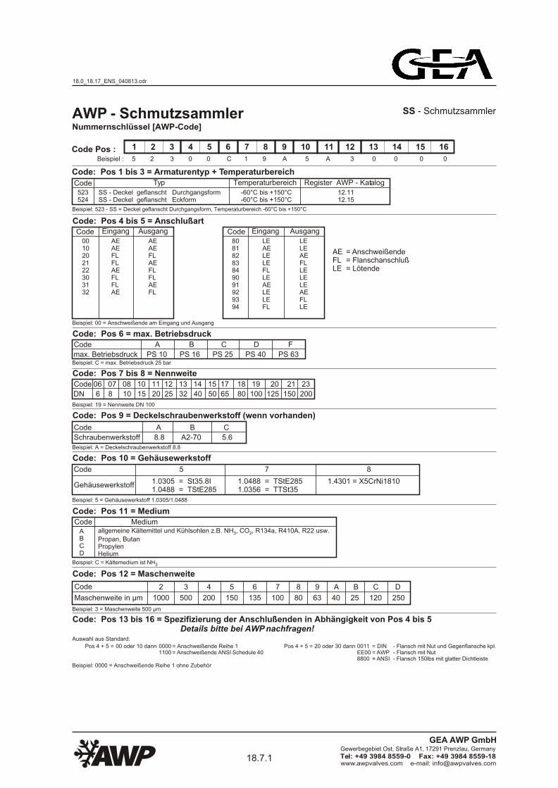
AWP - service valves
1 2 3 4 5 6 7 8 9 10 11 12 13 14 15 16
0 6 1 6 2 C 1 0 A 5 A 3 0 2 0 2
Code061062
-20°C to +100°C-20°C to +100°C
2.12.2
Code6062
Code Pos :
AVRS - service valve
example: 061 - AVRS = cover screwed globe type, temperature range -20°C bis +100°C
SEAE
SESE
example: 62 = welding end on inlet and screwed end on outlet
Code
DN
06 07 08 10
6 8 10 15
Code: Pos 12 = handwheel / cap
example: 3 = valve are delivered with cap
Codehandwheel / cap
1 2 3 4 without handwheel and cap with handwheel with cap with handwheel and cap
choice of standard valves:
Code: Pos 13 to 16 = specification of valve connection details please request AWP !
= welding end= screwed end
AESE
Code: Pos 4 to 5 = end connectionsinlet outlet
Code: Pos 6 = max. operating pressureCode
max. operating pressure
A B C D F
PS 10 PS 16 PS 25 PS 40 PS 63example: C = max. operating pressure 25 bar
Code: Pos 7 to 8 = size
example: 10 = size DN 15
Code: Pos 9 = material of cover screws (if flanged cover)
Code A B C
example: A = without cover screws
screw material 8.8 A2-70 5.6
Code: Pos 10 = body material
Code 5 7 8
example: 5 = body material 1.0305/1.0488
1.0305 = St35.8I1.0488 = TStE285
1.0488 = TStE2851.0356 = TTSt35
1.4301 = X5CrNi1810body material
identity code [AWP-code]
example :
AVRS - cover screwed globe typeAVRS - cover screwed angle type
typ temperature range register AWP - cataloge
Code: Pos 1 to 3 = valve type + temperature range
Code: Pos 11 = mediumCode medium
example: C = medium is NH3
general refrigerants and brines e.q. NH , CO , R134a, R410A, R22 and more3 2
propane, butanepropylenehelium
ABCD
example: 0202 = welding end range1 on inlet and screwed end G1/2“ + blind nut on outlet
= screwed end G3/8“ on outlet= screwed end G1/2“ on outlet= screwed end G1/2“ female travle end on outlet= screwed end G3/8“ female travle end on outlet
Pos 14 = 1 2 5 6
= welding end range 1 on inletPos 13 = 0
= without fittings on inletPos 15 = 0
= without fittings on outlet= with cap nut and tail on outlet= with blind nut on outlet= with double nut left / right on outlet= with cap nut and welde ball-type nipple on outlet= with cap nut and cutting ring on outlet
Pos 16 = 0 1 2 3 4 5
18.0_18.17_ENS_040813.cdr
18.1.2www.awpvalves.com e-mail: [email protected]
Gewerbegebiet Ost, Straße A1, 17291 Prenzlau, Germany
Tel: +49 3984 8559-0 Fax: +49 3984 8559-18
GEA AWP GmbH
Page 5
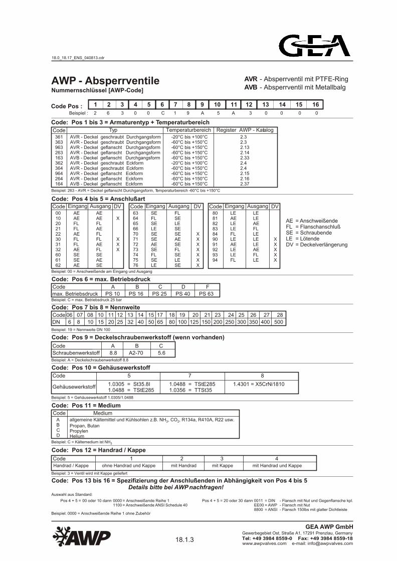
AWP - AbsperrventileAVB - Absperrventil mit MetallbalgNummernschlüssel [AWP-Code]
1 2 3 4 5 6 7 8 9 10 11 12 13 14 15 16
2 6 3 0 0 C 1 9 A 5 A 3 0 0 0 0Beispiel :
Code: Pos 1 bis 3 = Armaturentyp + Temperaturbereich
Code Typ Temperaturbereich Register AWP - Katalog
361363963263163362364964264164
AVR - Deckel geschraubt DurchgangsformAVR - Deckel geschraubt DurchgangsformAVR - Deckel geflanscht DurchgangsformAVR - Deckel geflanscht DurchgangsformAVB - Deckel geflanscht DurchgangsformAVR - Deckel geschraubt EckformAVR - Deckel geschraubt EckformAVR - Deckel geflanscht EckformAVR - Deckel geflanscht EckformAVB - Deckel geflanscht Eckform
-20°C bis +100°C-60°C bis +150°C-60°C bis +150°C-60°C bis +150°C-60°C bis +150°C-20°C bis +100°C-60°C bis +150°C-60°C bis +150°C-60°C bis +150°C-60°C bis +150°C
2.32.32.132.142.332.42.42.152.162.37
Code: Pos 4 bis 5 = AnschlußartCode
0010202122303132606162
6364656670717273747576
80818283849091929394
Code Pos :
AVR - Absperrventil mit PTFE-Ring
Beispiel: 263 - AVR = Deckel geflanscht Durchgangsform, Temperaturbereich -60°C bis +150°C
Eingang
AEAEFLFLAEFLFLAESESEAE
Ausgang
AEAEFLAEFLFLAEFLSEAESE
DV
X
XXX
Code Eingang
SEFLSELESESEAESEFLSELE
Ausgang
FLSELESESEAESEFLSELESE
DV
XXXXXXX
Code Eingang
LEAELELEFLLEAELELEFL
Ausgang
LELEAEFLLELELEAEFLLE
DV
XXXXX
= Anschweißende= Flanschanschluß= Schraubende= Lötende= Deckelverlängerung
Beispiel: 00 = Anschweißende am Eingang und Ausgang
Code: Pos 6 = max. BetriebsdruckCode
max. Betriebsdruck
A B C D F
PS 10 PS 16 PS 25 PS 40 PS 63Beispiel: C = max. Betriebsdruck 25 bar
Code: Pos 7 bis 8 = NennweiteCode
DN
06 07 08 10 11 12 13 14 15 17 18 19 20 21 23 24 25 26 27 28
6 8 10 15 20 25 32 40 50 65 80 100 125 150 200 250 300 350 400 500
Beispiel: 19 = Nennweite DN 100
Code: Pos 9 = Deckelschraubenwerkstoff (wenn vorhanden)
Code A B C
Beispiel: A = Deckelschraubenwerkstoff 8.8
Schraubenwerkstoff 8.8 A2-70 5.6
Code: Pos 10 = Gehäusewerkstoff
Code 5 7 8
Beispiel: 5 = Gehäusewerkstoff 1.0305/1.0488
1.0305 = St35.8I1.0488 = TStE285
Code: Pos 11 = MediumCode Medium
Beispiel: C = Kältemedium ist NH3
allgemeine Kältemittel und Kühlsohlen z.B. NH , CO , R134a, R410A, R22 usw.3 2
Propan, ButanPropylenHelium
ABCD
Code: Pos 12 = Handrad / Kappe
CodeHandrad / Kappe
Beispiel: 3 = Ventil wird mit Kappe geliefert
1.0488 = TStE2851.0356 = TTSt35
1.4301 = X5CrNi1810Gehäusewerkstoff
Code: Pos 13 bis 16 = Spezifizierung der Anschlußenden in Abhängigkeit von Pos 4 bis 5 Details bitte bei AWP nachfragen!
Beispiel: 0000 = Anschweißende Reihe 1 ohne Zubehör
1 2 3 4 ohne Handrad und Kappe mit Handrad mit Kappe mit Handrad und Kappe
= Anschweißende Reihe 1= Anschweißende ANSI Schedule 40
- Flansch mit Nut und Gegenflansche kpl.- Flansch mit Nut- Flansch 150lbs mit glatter Dichtleiste
Auswahl aus Standard:
Pos 4 + 5 = 00 oder 10 dann 00001100
Pos 4 + 5 = 20 oder 30 dann 0011EE008800
= DIN= AWP= ANSI
AEFLSELEDV
18.0_18.17_ENS_040813.cdr
18.1.3www.awpvalves.com e-mail: [email protected]
Gewerbegebiet Ost, Straße A1, 17291 Prenzlau, Germany
Tel: +49 3984 8559-0 Fax: +49 3984 8559-18
GEA AWP GmbH
Page 6
AWP - shut off valvesidentity code [AWP-code]
1 2 3 4 5 6 7 8 9 10 11 12 13 14 15 16
2 6 3 0 0 C 1 9 A 5 A 3 0 0 0 0example :
Code: Pos 1 to 3 = valve type + temperature range
Code typ temperature range register AWP - cataloge
361363963263163362364964264164
AVR - cover screwed globe typeAVR - cover screwed globe typeAVR - cover flanged globe typeAVR - cover flanged globe typeAVB - cover flanged globe typeAVR - cover screwed angle typeAVR - cover screwed angle typeAVR - cover flanged angle typeAVR - cover flanged angle typeAVB - cover flanged angle type
-20°C to +100°C-60°C to +150°C-60°C to +150°C-60°C to +150°C-60°C to +150°C-20°C to +100°C-60°C to +150°C-60°C to +150°C-60°C to +150°C-60°C to +150°C
2.32.32.132.142.332.42.42.152.162.37
Code: Pos 4 to 5 = end connectionsCode
0010202122303132606162
6364656670717273747576
80818283849091929394
Code Pos :
AVR - shut off valve with PTFE - ringAVB - shut off valve with metal bellow
example: 263 - AVR = cover flanged globe type, temperature range -60°C to +150°C
inlet
AEAEFLFLAEFLFLAESESEAE
outlet
AEAEFLAEFLFLAEFLSEAESE
DV
X
XXX
Code inlet
SEFLSELESESEAESEFLSELE
outlet
FLSELESESEAESEFLSELESE
DV
XXXXXXX
Code inlet
LEAELELEFLLEAELELEFL
outlet
LELEAEFLLELELEAEFLLE
DV
XXXXX
= welding end= flange connection= screwed end= solder end= cover extension
example: 00 = welding ends on inlet and outlet
Code: Pos 6 = max. operating pressureCode
max. operating pressure
A B C D F
PS 10 PS 16 PS 25 PS 40 PS 63example: C = max. operating pressure 25 bar
Code: Pos 7 to 8 = sizeCode
DN
06 07 08 10 11 12 13 14 15 17 18 19 20 21 23 24 25 26 27 28
6 8 10 15 20 25 32 40 50 65 80 100 125 150 200 250 300 350 400 500
example: 19 = size DN 100
Code: Pos 9 = material of cover screws (if flanged cover)
Code A B C
example: A = material of cover screws 8.8
screw material 8.8 A2-70 5.6
Code: Pos 10 = body material
Code 5 7 8
example: 5 = body material 1.0305/1.0488
1.0305 = St35.8I1.0488 = TStE285
Code: Pos 11 = mediumCode medium
example: C = medium is NH3
general refrigerants and brines e.q. NH , CO , R134a, R410A, R22 and more3 2
propane, butanepropylenehelium
ABCD
Code: Pos 12 = handwheel / cap
example: 3 = valve are delivered with cap
1.0488 = TStE2851.0356 = TTSt35
1.4301 = X5CrNi1810body material
Codehandwheel / cap
1 2 3 4 without handwheel and cap with handwheel with cap with handwheel and cap
example: 0000 = welding end range 1 without fittings
= welding end range 1= welding end ANSI Schedule 40
- flange with groove and counterflanges cpl.- flange with groove- flange 150lbs with raised face
choice of standard valves:
Pos 4 + 5 = 00 or 10 then 00001100
Pos 4 + 5 = 20 or 30 then 0011EE008800
= DIN= AWP= ANSI
Code: Pos 13 to 16 = specification of valve connection depending on Pos 4 to 5 details please request AWP !
AEFLSELEDV
18.0_18.17_ENS_040813.cdr
18.1.4www.awpvalves.com e-mail: [email protected]
Gewerbegebiet Ost, Straße A1, 17291 Prenzlau, Germany
Tel: +49 3984 8559-0 Fax: +49 3984 8559-18
GEA AWP GmbH
Page 7
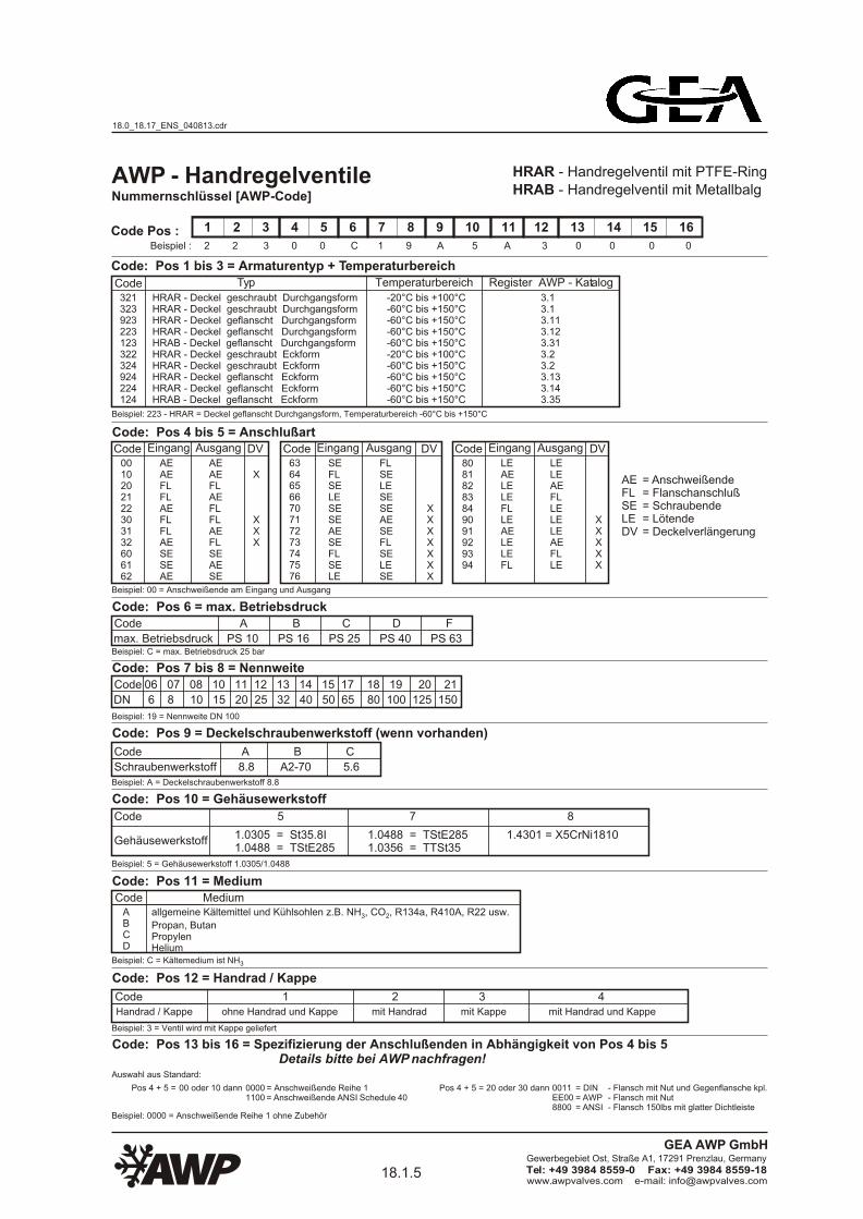
AWP - HandregelventileHRAB - Handregelventil mit MetallbalgNummernschlüssel [AWP-Code]
1 2 3 4 5 6 7 8 9 10 11 12 13 14 15 16
2 2 3 0 0 C 1 9 A 5 A 3 0 0 0 0Beispiel :
Code: Pos 1 bis 3 = Armaturentyp + Temperaturbereich
Code Typ Temperaturbereich Register AWP - Katalog
321323923223123322324924224124
HRAR - Deckel geschraubt DurchgangsformHRAR - Deckel geschraubt DurchgangsformHRAR - Deckel geflanscht DurchgangsformHRAR - Deckel geflanscht DurchgangsformHRAB - Deckel geflanscht DurchgangsformHRAR - Deckel geschraubt EckformHRAR - Deckel geschraubt EckformHRAR - Deckel geflanscht EckformHRAR - Deckel geflanscht EckformHRAB - Deckel geflanscht Eckform
-20°C bis +100°C-60°C bis +150°C-60°C bis +150°C-60°C bis +150°C-60°C bis +150°C-20°C bis +100°C-60°C bis +150°C-60°C bis +150°C-60°C bis +150°C-60°C bis +150°C
3.13.13.113.123.313.23.23.133.143.35
Code: Pos 4 bis 5 = AnschlußartCode
0010202122303132606162
6364656670717273747576
80818283849091929394
Code Pos :
HRAR - Handregelventil mit PTFE-Ring
Beispiel: 223 - HRAR = Deckel geflanscht Durchgangsform, Temperaturbereich -60°C bis +150°C
Eingang
AEAEFLFLAEFLFLAESESEAE
Ausgang
AEAEFLAEFLFLAEFLSEAESE
DV
X
XXX
Code Eingang
SEFLSELESESEAESEFLSELE
Ausgang
FLSELESESEAESEFLSELESE
DV
XXXXXXX
Code Eingang
LEAELELEFLLEAELELEFL
Ausgang
LELEAEFLLELELEAEFLLE
DV
XXXXX
Beispiel: 00 = Anschweißende am Eingang und Ausgang
Code: Pos 6 = max. BetriebsdruckCode
max. Betriebsdruck
A B C D F
PS 10 PS 16 PS 25 PS 40 PS 63Beispiel: C = max. Betriebsdruck 25 bar
Code: Pos 7 bis 8 = NennweiteCode
DN
06 07 08 10 11 12 13 14 15 17 18 19 20 21
6 8 10 15 20 25 32 40 50 65 80 100 125 150
Beispiel: 19 = Nennweite DN 100
Code: Pos 9 = Deckelschraubenwerkstoff (wenn vorhanden)
Code A B C
Beispiel: A = Deckelschraubenwerkstoff 8.8
Schraubenwerkstoff 8.8 A2-70 5.6
Code: Pos 10 = Gehäusewerkstoff
Code 5 7 8
Beispiel: 5 = Gehäusewerkstoff 1.0305/1.0488
1.0305 = St35.8I1.0488 = TStE285
Code: Pos 11 = MediumCode Medium
Beispiel: C = Kältemedium ist NH3
ABCD
Code: Pos 12 = Handrad / Kappe
Beispiel: 3 = Ventil wird mit Kappe geliefert
1.0488 = TStE2851.0356 = TTSt35
1.4301 = X5CrNi1810Gehäusewerkstoff
CodeHandrad / Kappe
1 2 3 4 ohne Handrad und Kappe mit Handrad mit Kappe mit Handrad und Kappe
Beispiel: 0000 = Anschweißende Reihe 1 ohne Zubehör
Auswahl aus Standard:
Code: Pos 13 bis 16 = Spezifizierung der Anschlußenden in Abhängigkeit von Pos 4 bis 5 Details bitte bei AWP nachfragen!
= Anschweißende Reihe 1= Anschweißende ANSI Schedule 40
- Flansch mit Nut und Gegenflansche kpl.- Flansch mit Nut- Flansch 150lbs mit glatter Dichtleiste
Pos 4 + 5 = 00 oder 10 dann 00001100
Pos 4 + 5 = 20 oder 30 dann 0011EE008800
= DIN= AWP= ANSI
= Anschweißende= Flanschanschluß= Schraubende= Lötende= Deckelverlängerung
AEFLSELEDV
allgemeine Kältemittel und Kühlsohlen z.B. NH , CO , R134a, R410A, R22 usw.3 2
Propan, ButanPropylenHelium
18.0_18.17_ENS_040813.cdr
18.1.5www.awpvalves.com e-mail: [email protected]
Gewerbegebiet Ost, Straße A1, 17291 Prenzlau, Germany
Tel: +49 3984 8559-0 Fax: +49 3984 8559-18
GEA AWP GmbH
Page 8
AWP - regulating valves
1 2 3 4 5 6 7 8 9 10 11 12 13 14 15 16
2 2 3 0 0 C 1 9 A 5 A 3 0 0 0 0
Code typ
321323923223123322324924224124
-20°C to +100°C-60°C to +150°C-60°C to +150°C-60°C to +150°C-60°C to +150°C-20°C to +100°C-60°C to +150°C-60°C to +150°C-60°C to +150°C-60°C to +150°C
3.13.13.113.123.313.23.23.133.143.35
Code0010202122303132606162
6364656670717273747576
80818283849091929394
Code Pos :
HRAR - regulating valve with PTFE-ringHRAB - regulating valve with metal bellow
AEAEFLFLAEFLFLAESESEAE
AEAEFLAEFLFLAEFLSEAESE
DV
X
XXX
CodeSEFLSELESESEAESEFLSELE
FLSELESESEAESEFLSELESE
DV
XXXXXXX
CodeLEAELELEFLLEAELELEFL
LELEAEFLLELELEAEFLLE
DV
XXXXX
Code
DN
06 07 08 10 11 12 13 14 15 17 18 19 20 21
6 8 10 15 20 25 32 40 50 65 80 100 125 150
Code: Pos 12 = handwheel / cap
example: 3 = valve are delivered with cap
Codehandwheel / cap
1 2 3 4 without handwheel and cap with handwheel with cap with handwheel and cap
example: 0000 = welding end range 1 without fittings
= welding end range 1= welding end ANSI Schedule 40
- flange with groove and counterflanges cpl.- flange with groove- flange 150lbs with raised face
choice of standard valves:
Pos 4 + 5 = 00 or 10 then 00001100
Pos 4 + 5 = 20 or 30 then 0011EE008800
= DIN= AWP= ANSI
Code: Pos 13 to 16 = specification of valve connection depending on Pos 4 to 5 details please request AWP !
identity code [AWP-code]
example :
Code: Pos 1 to 3 = valve type + temperature range
Code: Pos 4 to 5 = end connections
Code: Pos 6 = max. operating pressureCode
max. operating pressure
A B C D F
PS 10 PS 16 PS 25 PS 40 PS 63
Code: Pos 7 to 8 = size
Code: Pos 9 = material of cover screws (if flanged cover)
Code A B C
example: A = material of cover srews 8.8
screw material 8.8 A2-70 5.6
Code: Pos 10 = body material
Code 5 7 8
example: 5 = body material 1.0305/1.0488
1.0305 = St35.8I1.0488 = TStE285
1.0488 = TStE2851.0356 = TTSt35
1.4301 = X5CrNi1810body material
example: 00 = welding ends on inlet and outlet
example: C = max. operating pressure 25 bar
example: 19 = size DN 100
temperature range register AWP - cataloge
HRAR - cover screwed globe typeHRAR - cover screwed globe typeHRAR - cover flanged globe typeHRAR - cover flanged globe typeHRAB - cover flanged globe typeHRAR - cover screwed angle typeHRAR - cover screwed angle typeHRAR - cover flanged angle typeHRAR - cover flanged angle typeHRAB - cover flanged angle type
example: 223 - HRAR = cover flanged globe type, temperature range -60°C to +150°C
inlet outlet inlet outlet inlet outlet
= welding end= flange connection= screwed end= solder end= cover extension
AEFLSELEDV
Code: Pos 11 = mediumCode medium
example: C = medium is NH3
general refrigerants and brines e.q. NH , CO , R134a, R410A, R22 and more3 2
propane, butanepropylenehelium
ABCD
18.0_18.17_ENS_040813.cdr
18.1.6www.awpvalves.com e-mail: [email protected]
Gewerbegebiet Ost, Straße A1, 17291 Prenzlau, Germany
Tel: +49 3984 8559-0 Fax: +49 3984 8559-18
GEA AWP GmbH
Page 9
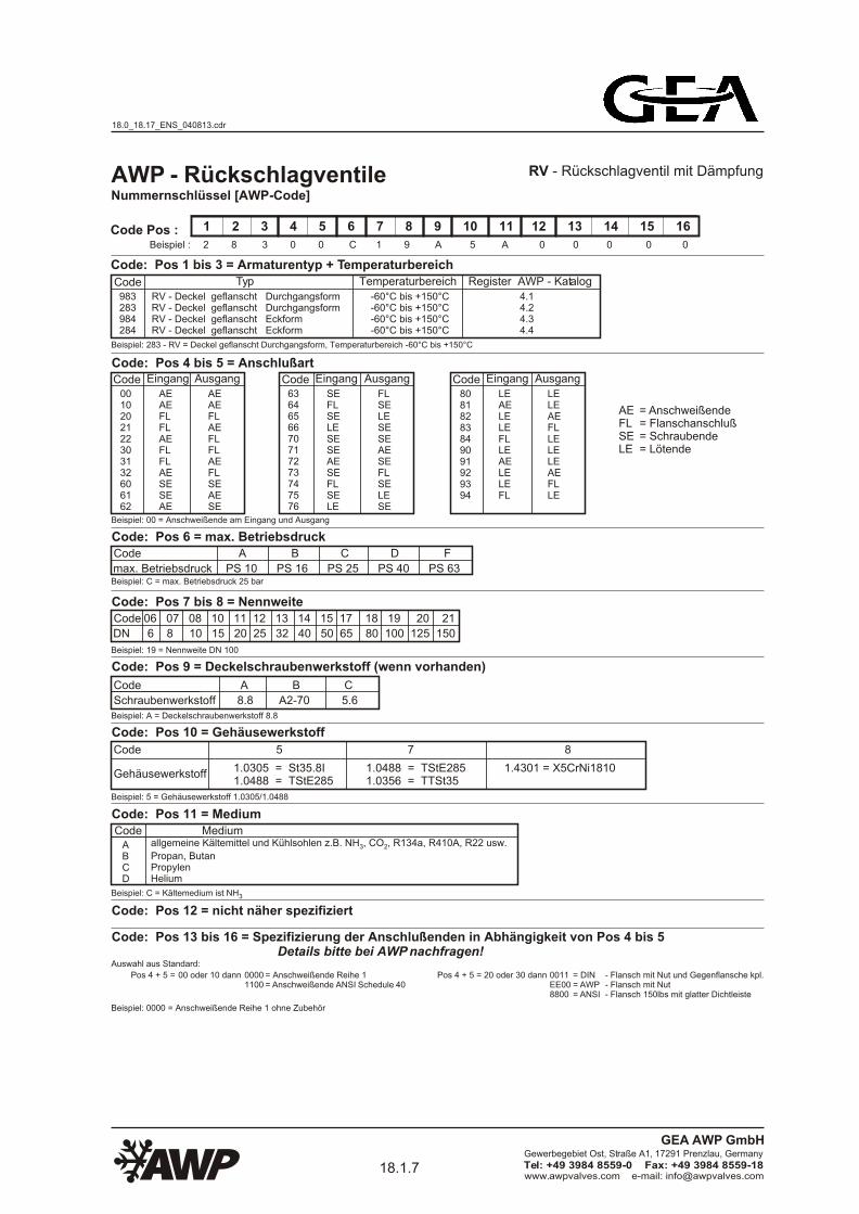
AWP - RückschlagventileNummernschlüssel [AWP-Code]
1 2 3 4 5 6 7 8 9 10 11 12 13 14 15 16
2 8 3 0 0 C 1 9 A 5 A 0 0 0 0 0Beispiel :
Code: Pos 1 bis 3 = Armaturentyp + Temperaturbereich
Code Typ Temperaturbereich Register AWP - Katalog
983283984284
RV - Deckel geflanscht DurchgangsformRV - Deckel geflanscht DurchgangsformRV - Deckel geflanscht EckformRV - Deckel geflanscht Eckform
-60°C bis +150°C-60°C bis +150°C-60°C bis +150°C-60°C bis +150°C
4.14.24.34.4
Code: Pos 4 bis 5 = AnschlußartCode
0010202122303132606162
6364656670717273747576
80818283849091929394
Code Pos :
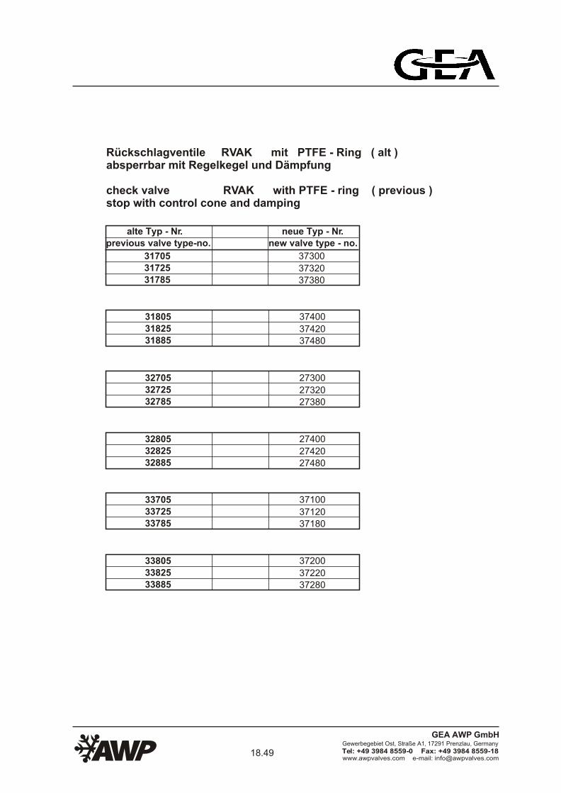
RV - Rückschlagventil mit Dämpfung
Beispiel: 283 - RV = Deckel geflanscht Durchgangsform, Temperaturbereich -60°C bis +150°C
Eingang
AEAEFLFLAEFLFLAESESEAE
Ausgang
AEAEFLAEFLFLAEFLSEAESE
Code Eingang
SEFLSELESESEAESEFLSELE
Ausgang
FLSELESESEAESEFLSELESE
Code Eingang
LEAELELEFLLEAELELEFL
Ausgang
LELEAEFLLELELEAEFLLE
Beispiel: 00 = Anschweißende am Eingang und Ausgang
Code: Pos 6 = max. BetriebsdruckCode
max. Betriebsdruck
A B C D F
PS 10 PS 16 PS 25 PS 40 PS 63Beispiel: C = max. Betriebsdruck 25 bar
Code: Pos 7 bis 8 = Nennweite
Beispiel: 19 = Nennweite DN 100
Code: Pos 9 = Deckelschraubenwerkstoff (wenn vorhanden)
Code A B C
Beispiel: A = Deckelschraubenwerkstoff 8.8
Schraubenwerkstoff 8.8 A2-70 5.6
Code: Pos 10 = Gehäusewerkstoff
Code 5 7 8
Beispiel: 5 = Gehäusewerkstoff 1.0305/1.0488
1.0305 = St35.8I1.0488 = TStE285
Code: Pos 11 = MediumCode Medium
Beispiel: C = Kältemedium ist NH3
ABCD
Code: Pos 12 = nicht näher spezifiziert
1.0488 = TStE2851.0356 = TTSt35
1.4301 = X5CrNi1810Gehäusewerkstoff
Code
DN
06 07 08 10 11 12 13 14 15 17 18 19 20 21
6 8 10 15 20 25 32 40 50 65 80 100 125 150
Beispiel: 0000 = Anschweißende Reihe 1 ohne Zubehör
Code: Pos 13 bis 16 = Spezifizierung der Anschlußenden in Abhängigkeit von Pos 4 bis 5 Details bitte bei AWP nachfragen! Auswahl aus Standard:
= Anschweißende Reihe 1= Anschweißende ANSI Schedule 40
- Flansch mit Nut und Gegenflansche kpl.- Flansch mit Nut- Flansch 150lbs mit glatter Dichtleiste
Pos 4 + 5 = 00 oder 10 dann 00001100
Pos 4 + 5 = 20 oder 30 dann 0011EE008800
= DIN= AWP= ANSI
= Anschweißende= Flanschanschluß= Schraubende= Lötende
AEFLSELE
allgemeine Kältemittel und Kühlsohlen z.B. NH , CO , R134a, R410A, R22 usw.3 2
Propan, ButanPropylenHelium
18.0_18.17_ENS_040813.cdr
18.1.7www.awpvalves.com e-mail: [email protected]
Gewerbegebiet Ost, Straße A1, 17291 Prenzlau, Germany
Tel: +49 3984 8559-0 Fax: +49 3984 8559-18
GEA AWP GmbH
Page 10
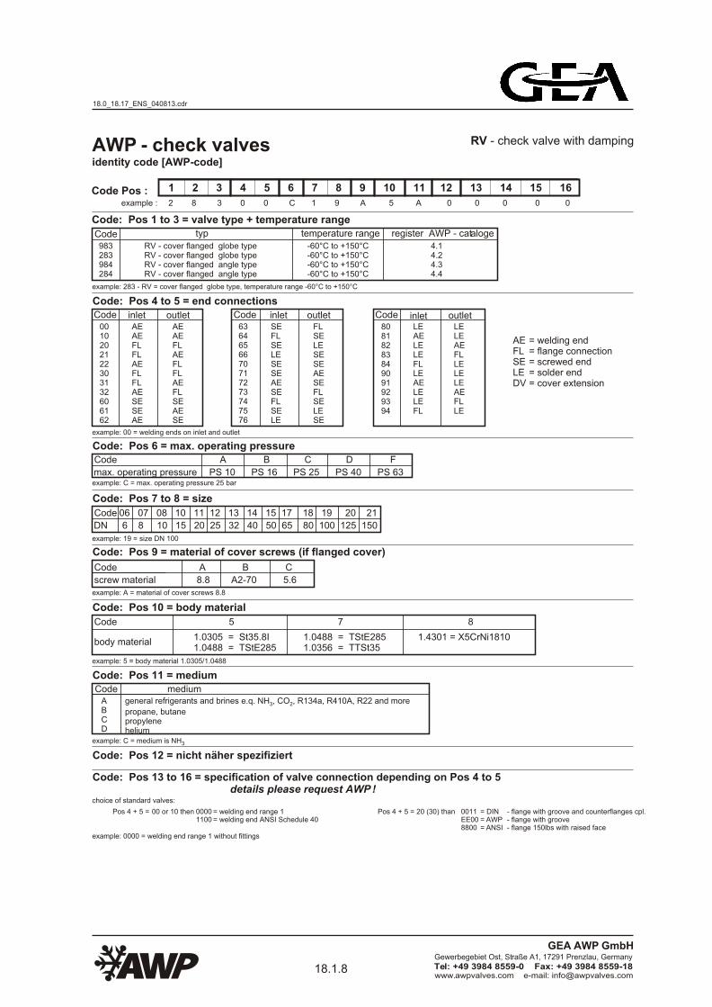
AWP - check valves
1 2 3 4 5 6 7 8 9 10 11 12 13 14 15 16
2 8 3 0 0 C 1 9 A 5 A 0 0 0 0 0
Code typ
983283984284
-60°C to +150°C-60°C to +150°C-60°C to +150°C-60°C to +150°C
4.14.24.34.4
Code0010202122303132606162
6364656670717273747576
80818283849091929394
Code Pos :
RV - check valve with damping
AEAEFLFLAEFLFLAESESEAE
AEAEFLAEFLFLAEFLSEAESE
CodeSEFLSELESESEAESEFLSELE
FLSELESESEAESEFLSELESE
CodeLEAELELEFLLEAELELEFL
LELEAEFLLELELEAEFLLE
Code: Pos 12 = nicht näher spezifiziert
Code
DN
06 07 08 10 11 12 13 14 15 17 18 19 20 21
6 8 10 15 20 25 32 40 50 65 80 100 125 150
example: 0000 = welding end range 1 without fittings
= welding end range 1= welding end ANSI Schedule 40
- flange with groove and counterflanges cpl.- flange with groove- flange 150lbs with raised face
choice of standard valves:
Pos 4 + 5 = 00 or 10 then 00001100
Pos 4 + 5 = 20 (30) than 0011EE008800
= DIN= AWP= ANSI
Code: Pos 13 to 16 = specification of valve connection depending on Pos 4 to 5 details please request AWP !
identity code [AWP-code]
example :
Code: Pos 1 to 3 = valve type + temperature rangetemperature range register AWP - cataloge
RV - cover flanged globe typeRV - cover flanged globe typeRV - cover flanged angle typeRV - cover flanged angle type
example: 283 - RV = cover flanged globe type, temperature range -60°C to +150°C
= welding end= flange connection= screwed end= solder end= cover extension
AEFLSELEDV
Code: Pos 4 to 5 = end connections
inlet outlet inlet outlet inlet outlet
Code: Pos 6 = max. operating pressureCode
max. operating pressure
A B C D F
PS 10 PS 16 PS 25 PS 40 PS 63example: C = max. operating pressure 25 bar
Code: Pos 7 to 8 = size
example: 19 = size DN 100
Code: Pos 9 = material of cover screws (if flanged cover)
Code A B C
example: A = material of cover screws 8.8
screw material 8.8 A2-70 5.6
Code: Pos 10 = body material
Code 5 7 8
example: 5 = body material 1.0305/1.0488
1.0305 = St35.8I1.0488 = TStE285
1.0488 = TStE2851.0356 = TTSt35
1.4301 = X5CrNi1810body material
example: 00 = welding ends on inlet and outlet
Code: Pos 11 = mediumCode medium
example: C = medium is NH3
general refrigerants and brines e.q. NH , CO , R134a, R410A, R22 and more3 2
propane, butanepropylenehelium
ABCD
18.0_18.17_ENS_040813.cdr
18.1.8www.awpvalves.com e-mail: [email protected]
Gewerbegebiet Ost, Straße A1, 17291 Prenzlau, Germany
Tel: +49 3984 8559-0 Fax: +49 3984 8559-18
GEA AWP GmbH
Page 11
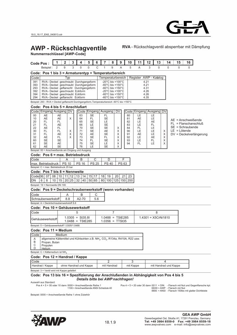
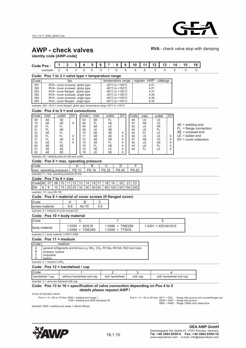
Nummernschlüssel [AWP-Code]
1 2 3 4 5 6 7 8 9 10 11 12 13 14 15 16
2 9 3 0 0 C 1 9 A 5 A 3 0 0 0 0Beispiel :
Code: Pos 1 bis 3 = Armaturentyp + Temperaturbereich
Code Typ Temperaturbereich Register AWP - Katalog
391393293392394294
RVA - Deckel geschraubt DurchgangsformRVA - Deckel geschraubt DurchgangsformRVA - Deckel geflanscht DurchgangsformRVA - Deckel geschraubt EckformRVA - Deckel geschraubt EckformRVA - Deckel geflanscht Eckform
-20°C bis +100°C-60°C bis +150°C-60°C bis +150°C-20°C bis +100°C-60°C bis +150°C-60°C bis +150°C
4.214.214.314.264.264.35
Code: Pos 4 bis 5 = AnschlußartCode
0010202122303132606162
6364656670717273747576
80818283849091929394
Code Pos :
RVA - Rückschlagventil absperrbar mit Dämpfung
Beispiel: 293 - RVA = Deckel geflanscht Durchgangsform, Temperaturbereich -60°C bis +150°C
Eingang
AEAEFLFLAEFLFLAESESEAE
Ausgang
AEAEFLAEFLFLAEFLSEAESE
DV
X
XXX
Code Eingang
SEFLSELESESEAESEFLSELE
Ausgang
FLSELESESEAESEFLSELESE
DV
XXXXXXX
Code Eingang
LEAELELEFLLEAELELEFL
Ausgang
LELEAEFLLELELEAEFLLE
DV
XXXXX
Beispiel: 00 = Anschweißende am Eingang und Ausgang
Code: Pos 6 = max. BetriebsdruckCode
max. Betriebsdruck
A B C D F
PS 10 PS 16 PS 25 PS 40 PS 63Beispiel: C = max. Betriebsdruck 25 bar
Code: Pos 7 bis 8 = NennweiteCode
DN
06 07 08 10 11 12 13 14 15 17 18 19 20 21 23
6 8 10 15 20 25 32 40 50 65 80 100 125 150 200
Beispiel: 19 = Nennweite DN 100
Code: Pos 9 = Deckelschraubenwerkstoff (wenn vorhanden)
Code A B C
Beispiel: A = Deckrlschraubenwerkstoff 8.8
Schraubenwerkstoff 8.8 A2-70 5.6
Code: Pos 10 = Gehäusewerkstoff
Code 5 7 8
Beispiel: 5 = Gehäusewerkstoff 1.0305/1.0488
1.0305 = St35.8I1.0488 = TStE285
Code: Pos 11 = MediumCode Medium
Beispiel: C = Kältemedium ist NH3
ABCD
Code: Pos 12 = Handrad / Kappe
Beispiel: 3 = Ventil wird mit Kappe geliefert
1.0488 = TStE2851.0356 = TTSt35
1.4301 = X5CrNi1810Gehäusewerkstoff
AWP - Rückschlagventile
CodeHandrad / Kappe
1 2 3 4 ohne Handrad und Kappe mit Handrad mit Kappe mit Handrad und Kappe
Beispiel: 0000 = Anschweißende Reihe 1 ohne Zubehör
Code: Pos 13 bis 16 = Spezifizierung der Anschlußenden in Abhängigkeit von Pos 4 bis 5 Details bitte bei AWP nachfragen! Auswahl aus Standard:
= Anschweißende Reihe 1= Anschweißende ANSI Schedule 40
- Flansch mit Nut und Gegenflansche kpl.- Flansch mit Nut- Flansch 150lbs mit glatter Dichtleiste
Pos 4 + 5 = 00 oder 10 dann 00001100
Pos 4 + 5 = 20 oder 30 dann 0011EE008800
= DIN= AWP= ANSI
= Anschweißende= Flanschanschluß= Schraubende= Lötende= Deckelverlängerung
AEFLSELEDV
allgemeine Kältemittel und Kühlsohlen z.B. NH , CO , R134a, R410A, R22 usw.3 2
Propan, ButanPropylenHelium
18.0_18.17_ENS_040813.cdr
18.1.9www.awpvalves.com e-mail: [email protected]
Gewerbegebiet Ost, Straße A1, 17291 Prenzlau, Germany
Tel: +49 3984 8559-0 Fax: +49 3984 8559-18
GEA AWP GmbH
Page 12
1 2 3 4 5 6 7 8 9 10 11 12 13 14 15 16
2 9 3 0 0 C 1 9 A 5 A 3 0 0 0 0
Code391393293392394294
-20°C to +100°C-60°C to +150°C-60°C to +150°C-20°C to +100°C-60°C to +150°C-60°C to +150°C
4.214.214.314.264.264.35
Code0010202122303132606162
6364656670717273747576
80818283849091929394
Code Pos :
RVA - check valve stop with damping
AEAEFLFLAEFLFLAESESEAE
AEAEFLAEFLFLAEFLSEAESE
DV
X
XXX
CodeSEFLSELESESEAESEFLSELE
FLSELESESEAESEFLSELESE
DV
XXXXXXX
CodeLEAELELEFLLEAELELEFL
LELEAEFLLELELEAEFLLE
DV
XXXXX
Code
DN
06 07 08 10 11 12 13 14 15 17 18 19 20 21 23
6 8 10 15 20 25 32 40 50 65 80 100 125 150 200
Code: Pos 12 = handwheel / cap
example: 3 = valve are delivered with cap
Codehandwheel / cap
1 2 3 4 without handwheel and cap with handwheel with cap with handwheel and cap
example: 0000 = welding end range 1 without fittings
= welding end range 1= welding end ANSI Schedule 40
- flange with groove and counterflanges cpl.- flange with groove- flange 150lbs with raised face
choice of standard valves:
Pos 4 + 5 = 00 or 10 then 00001100
Pos 4 + 5 = 20 or 30 then 0011EE008800
= DIN= AWP= ANSI
Code: Pos 13 to 16 = specification of valve connection depending on Pos 4 to 5 details please request AWP !
= welding end= flange connection= screwed end= solder end= cover extension
AEFLSELEDV
Code: Pos 4 to 5 = end connections
inlet outlet inlet outlet inlet outlet
Code: Pos 6 = max. operating pressureCode
max. operating pressure
A B C D F
PS 10 PS 16 PS 25 PS 40 PS 63example: C = max. operating pressure 25 bar
Code: Pos 7 to 8 = size
example: 19 = size DN 100
Code: Pos 9 = material of cover screws (if flanged cover)
Code A B C
example: A = material of cover screws 8.8
screw material 8.8 A2-70 5.6
Code: Pos 10 = body material
Code 5 7 8
example: 5 = body material 1.0305/1.0488
1.0305 = St35.8I1.0488 = TStE285
1.0488 = TStE2851.0356 = TTSt35
1.4301 = X5CrNi1810body material
identity code [AWP-code]
example :
AWP - check valves
RVA - cover screwed globe typeRVA - cover screwed globe typeRVA - cover flanged globe typeRVA - cover screwed angle typeRVA - cover screwed angle typeRVA - cover flanged angle type
typ temperature range register AWP - cataloge
example: 293 - RVA = cover flanged globe type, temperature range -60°C to +150°C
Code: Pos 1 to 3 = valve type + temperature range
example: 00 = welding ends on inlet and outlet
Code: Pos 11 = mediumCode medium
example: C = medium is NH3
general refrigerants and brines e.q. NH , CO , R134a, R410A, R22 and more3 2
propane, butanepropylenehelium
ABCD
18.0_18.17_ENS_040813.cdr
18.1.10www.awpvalves.com e-mail: [email protected]
Gewerbegebiet Ost, Straße A1, 17291 Prenzlau, Germany
Tel: +49 3984 8559-0 Fax: +49 3984 8559-18
GEA AWP GmbH
Page 13
Nummernschlüssel [AWP-Code]
1 2 3 4 5 6 7 8 9 10 11 12 13 14 15 16
2 7 3 0 0 C 1 9 A 5 A 3 0 0 0 0Beispiel :
Code: Pos 1 bis 3 = Armaturentyp + Temperaturbereich
Code Typ Temperaturbereich Register AWP - Katalog
371373273372374274
RVAK - Deckel geschraubt DurchgangsformRVAK - Deckel geschraubt DurchgangsformRVAK - Deckel geflanscht DurchgangsformRVAK - Deckel geschraubt EckformRVAK - Deckel geschraubt EckformRVAK - Deckel geflanscht Eckform
-20°C bis +100°C-60°C bis +150°C-60°C bis +150°C-20°C bis +100°C-60°C bis +150°C-60°C bis +150°C
4.414.414.514.464.464.55
Code: Pos 4 bis 5 = AnschlußartCode
0010202122303132606162
6364656670717273747576
80818283849091929394
Code Pos :
RVAK - Rückschlagventil absperrbar mit Regelkegel mit Dämpfung
Beispiel: 273 - RVAK = Deckel geflanscht Durchgangsform, Temperaturbereich -60°C bis +150°C
Eingang
AEAEFLFLAEFLFLAESESEAE
Ausgang
AEAEFLAEFLFLAEFLSEAESE
DV
X
XXX
Code Eingang
SEFLSELESESEAESEFLSELE
Ausgang
FLSELESESEAESEFLSELESE
DV
XXXXXXX
Code Eingang
LEAELELEFLLEAELELEFL
Ausgang
LELEAEFLLELELEAEFLLE
DV
XXXXX
Beispiel: 00 = Anschweißende am Eingang und Ausgang
Code: Pos 6 = max. BetriebsdruckCode
max. Betriebsdruck
A B C D F
PS 10 PS 16 PS 25 PS 40 PS 63Beispiel: C = max. Betriebsdruck 25 bar
Code: Pos 7 bis 8 = NennweiteCode
DN
06 07 08 10 11 12 13 14 15 17 18 19 20
6 8 10 15 20 25 32 40 50 65 80 100 125
Beispiel: 19 = Nennweite DN 100
Code: Pos 9 = Deckelschraubenwerkstoff (wenn vorhanden)
Code A B C
Beispiel: A = Deckelschraubenwerkstoff 8.8
Schraubenwerkstoff 8.8 A2-70 5.6
Code: Pos 10 = Gehäusewerkstoff
Code 5 7 8
Beispiel: 5 = Gehäusewerkstoff 1.0305/1.0488
1.0305 = St35.8I1.0488 = TStE285
Code: Pos 11 = MediumCode Medium
Beispiel: C = Kältemedium ist NH3
ABCD
Code: Pos 12 = Handrad / Kappe
Beispiel: 3 = Ventil wird mit Kappe geliefert
1.0488 = TStE2851.0356 = TTSt35
1.4301 = X5CrNi1810Gehäusewerkstoff
AWP - Rückschlagventile
CodeHandrad / Kappe
1 2 3 4 ohne Handrad und Kappe mit Handrad mit Kappe mit Handrad und Kappe
Beispiel: 0000 = Anschweißende Reihe 1 ohne Zubehör
Code: Pos 13 bis 16 = Spezifizierung der Anschlußenden in Abhängigkeit von Pos 4 bis 5 Details bitte bei AWP nachfragen! Auswahl aus Standard:
= Anschweißende Reihe 1= Anschweißende ANSI Schedule 40
- Flansch mit Nut und Gegenflansche kpl.- Flansch mit Nut- Flansch 150lbs mit glatter Dichtleiste
Pos 4 + 5 = 00 oder 10 dann 00001100
Pos 4 + 5 = 20 oder 30 dann 0011EE008800
= DIN= AWP= ANSI
= Anschweißende= Flanschanschluß= Schraubende= Lötende= Deckelverlängerung
AEFLSELEDV
allgemeine Kältemittel und Kühlsohlen z.B. NH , CO , R134a, R410A, R22 usw.3 2
Propan, ButanPropylenHelium
18.0_18.17_ENS_040813.cdr
18.1.11www.awpvalves.com e-mail: [email protected]
Gewerbegebiet Ost, Straße A1, 17291 Prenzlau, Germany
Tel: +49 3984 8559-0 Fax: +49 3984 8559-18
GEA AWP GmbH
Page 14
1 2 3 4 5 6 7 8 9 10 11 12 13 14 15 16
2 7 3 0 0 C 1 9 A 5 A 3 0 0 0 0
Code371373273372374274
-20°C to +100°C-60°C to +150°C-60°C to +150°C-20°C to +100°C-60°C to +150°C-60°C to +150°C
4.414.414.514.464.464.55
Code0010202122303132606162
6364656670717273747576
80818283849091929394
Code Pos :
RVAK - check valve stop with control cone with damping
AEAEFLFLAEFLFLAESESEAE
AEAEFLAEFLFLAEFLSEAESE
DV
X
XXX
CodeSEFLSELESESEAESEFLSELE
FLSELESESEAESEFLSELESE
DV
XXXXXXX
CodeLEAELELEFLLEAELELEFL
LELEAEFLLELELEAEFLLE
DV
XXXXX
Code
DN
06 07 08 10 11 12 13 14 15 17 18 19 20
6 8 10 15 20 25 32 40 50 65 80 100 125
Code: Pos 12 = handwheel / cap
example: 3 = valve are delivered with cap
Codehandwheel / cap
1 2 3 4 without handwheel and cap with handwheel with cap with handwheel and cap
example: 0000 = welding end range 1 without fittings
= welding end range 1= welding end ANSI Schedule 40
- flange with groove and counterflanges cpl.- flange with groove- flange 150lbs with raised face
choice of standard valves:
Pos 4 + 5 = 00 or 10 then 00001100
Pos 4 + 5 = 20 or 30 then 0011EE008800
= DIN= AWP= ANSI
Code: Pos 13 to 16 = specification of valve connection depending on Pos 4 to 5 details please request AWP !
= welding end= flange connection= screwed end= solder end= cover extension
AEFLSELEDV
Code: Pos 4 to 5 = end connections
inlet outlet inlet outlet inlet outlet
Code: Pos 6 = max. operating pressureCode
max. operating pressure
A B C D F
PS 10 PS 16 PS 25 PS 40 PS 63example: C = max. operating pressure 25 bar
Code: Pos 7 to 8 = size
example: 19 = size DN 100
Code: Pos 9 = material of cover screws (if flanged cover)
Code A B C
example: A = material of cover screws 8.8
screw material 8.8 A2-70 5.6
Code: Pos 10 = body material
Code 5 7 8
example: 5 = body material 1.0305/1.0488
1.0305 = St35.8I1.0488 = TStE285
1.0488 = TStE2851.0356 = TTSt35
1.4301 = X5CrNi1810body material
identity code [AWP-code]
example :
AWP - check valves
example: 273 - RVAK = cover flanged globe type, temperature range -60°C to +150°C
RVAK - cover screwed globe typeRVAK - cover screwed globe typeRVAK - cover flanged globe typeRVAK - cover screwed angle typeRVAK - cover screwed angle typeRVAK - cover flanged angle type
typ temperature range register AWP - cataloge
Code: Pos 1 to 3 = valve type + temperature range
example: 00 = welding ends on inlet and outlet
Code: Pos 11 = mediumCode medium
example: C = medium is NH3
general refrigerants and brines e.q. NH , CO , R134a, R410A, R22 and more3 2
propane, butanepropylenehelium
ABCD
18.0_18.17_ENS_040813.cdr
18.1.12www.awpvalves.com e-mail: [email protected]
Gewerbegebiet Ost, Straße A1, 17291 Prenzlau, Germany
Tel: +49 3984 8559-0 Fax: +49 3984 8559-18
GEA AWP GmbH
Page 15
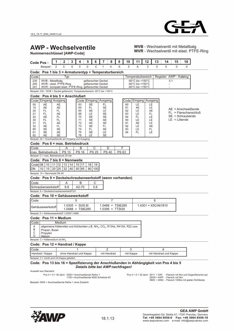
AWP - WechselventileNummernschlüssel [AWP-Code]
1 2 3 4 5 6 7 8 9 10 11 12 13 14 15 16
2 3 0 0 0 C 1 4 A 5 A 3 0 0 0 0Beispiel :
Code: Pos 1 bis 3 = Armaturentyp + Temperaturbereich
Code Typ Temperaturbereich Register AWP - Katalog
230240241
geflanschter Deckelgeflanschter Deckelgeflanschter Deckel
-60°C bis +150°C-60°C bis +150°C-60°C bis +150°C
5.1--
Code: Pos 4 bis 5 = AnschlußartCode
0010202122303132606162
6364656670717273747576
80818283849091929394
Code Pos :
WVB - Wechselventil mit MetallbalgWVR - Wechselventil mit elast. PTFE-Ring
Beispiel: 230 - WVB = Deckel geflanscht, Temperaturbereich -60°C bis +150°C
Eingang
AEAEFLFLAEFLFLAESESEAE
Ausgang
AEAEFLAEFLFLAEFLSEAESE
Code Eingang
SEFLSELESESEAESEFLSELE
Ausgang
FLSELESESEAESEFLSELESE
Code Eingang
LEAELELEFLLEAELELEFL
Ausgang
LELEAEFLLELELEAEFLLE
= Anschweißende= Flanschanschluß= Schraubende= Lötende
Beispiel: 00 = Anschweißende am Eingang und Ausgang
Code: Pos 6 = max. BetriebsdruckCode
max. Betriebsdruck
A B C D F
PS 10 PS 16 PS 25 PS 40 PS 63Beispiel: C = max. Betriebsdruck 25 bar
Code: Pos 7 bis 8 = NennweiteCode
DN
08 10 11 12 13 14 15 17 18 19
10 15 20 25 32 40 50 65 80 100
Beispiel: 14 = Nennweite DN 40
Code: Pos 9 = Deckelschraubenwerkstoff (wenn vorhanden)
Code A B C
Beispiel: A = Deckelschraubenwerkstoff 8.8
Schraubenwerkstoff 8.8 A2-70 5.6
Code: Pos 10 = Gehäusewerkstoff
Code 5 7 8
Beispiel: 5 = Gehäusewerkstoff 1.0305/1.0488
1.0305 = St35.8I1.0488 = TStE285
Code: Pos 11 = MediumCode Medium
Beispiel: C = Kältemedium ist NH3
allgemeine Kältemittel und Kühlsohlen z.B. NH , CO , R134a, R410A, R22 usw.3 2
Propan, ButanPropylenHelium
ABCD
Code: Pos 12 = Handrad / Kappe
CodeHandrad / Kappe
Beispiel: 3 = Ventil wird mit Kappe geliefert
1.0488 = TStE2851.0356 = TTSt35
1.4301 = X5CrNi1810Gehäusewerkstoff
Code: Pos 13 bis 16 = Spezifizierung der Anschlußenden in Abhängigkeit von Pos 4 bis 5 Details bitte bei AWP nachfragen!
Beispiel: 0000 = Anschweißende Reihe 1 ohne Zubehör
1 2 3 4 ohne Handrad und Kappe mit Handrad mit Kappe mit Handrad und Kappe
= Anschweißende Reihe 1= Anschweißende ANSI Schedule 40
- Flansch mit Nut und Gegenflansche kpl.- Flansch mit Nut- Flansch 150lbs mit glatter Dichtleiste
Auswahl aus Standard:
Pos 4 + 5 = 00 dann 00001100
Pos 4 + 5 = 20 dann 0011EE008800
= DIN= AWP= ANSI
AEFLSELE
WVB - MetallbalgWVR - elast. PTFE-RingWVR - kompakt elast. PTFE-Ring
18.0_18.17_ENS_040813.cdr
18.1.13www.awpvalves.com e-mail: [email protected]
Gewerbegebiet Ost, Straße A1, 17291 Prenzlau, Germany
Tel: +49 3984 8559-0 Fax: +49 3984 8559-18
GEA AWP GmbH
Page 16
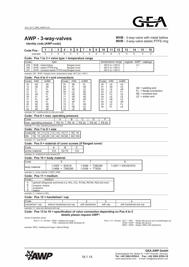
AWP - 3-way-valves
1 2 3 4 5 6 7 8 9 10 11 12 13 14 15 16
2 3 0 0 0 C 1 4 A 5 A 3 0 0 0 0
Code type temperature range
230240241
flanged coverflanged coverflanged cover
-60°C to +150°C-60°C to +150°C-60°C to +150°C
5.1--
Code Pos :
WVB - 3-way-valve with metal bellowWVR - 3-way-valve elastic PTFE-ring
example: 230 - WVB = flanged cover, temperature range -60°C bis +150°C
WVB - metal bellowWVR - elastic PTFE-ringWVR - compact elastic PTFE-ring
Code: Pos 4 to 5 = end connectionsCode
0010202122303132606162
6364656670717273747576
80818283849091929394
inlet
AEAEFLFLAEFLFLAESESEAE
outlet
AEAEFLAEFLFLAEFLSEAESE
Code inlet
SEFLSELESESEAESEFLSELE
outlet
FLSELESESEAESEFLSELESE
Code inlet
LEAELELEFLLEAELELEFL
outlet
LELEAEFLLELELEAEFLLE
= welding end= flange connection= screwed end= solder end
example: 00 = welding ends on inlet and outlet
Code: Pos 6 = max. operating pressureCode
max. operating pressure
A B C D F
PS 10 PS 16 PS 25 PS 40 PS 63example: C = max. operating pressure 25 bar
Code: Pos 7 to 8 = sizeCode
DN
08 10 11 12 13 14 15 17 18 19
10 15 20 25 32 40 50 65 80 100
example: 14 = size DN 40
Code: Pos 9 = material of cover screws (if flanged cover)
Code A B C
example: A = material of cover screws 8.8
screw material 8.8 A2-70 5.6
Code: Pos 10 = body material
Code 5 7 8
example: 5 = body material 1.0305/1.0488
1.0305 = St35.8I1.0488 = TStE285
Code: Pos 11 = mediumCode medium
example: C = medium is NH3
general refrigerants and brines e.q. NH , CO , R134a, R410A, R22 and more3 2
propane, butanepropylenehelium
ABCD
Code: Pos 12 = handwheel / cap
example: 3 = valve are delivered with cap
1.0488 = TStE2851.0356 = TTSt35
1.4301 = X5CrNi1810body material
Codehandwheel / cap
1 2 3 4 without handwheel and cap with handwheel with cap with handwheel and cap
example: 0000 = welding end range 1 without fittings
= welding end range 1= welding end ANSI Schedule 40
- flange with groove and counterflanges cpl.- flange with groove- flange 150lbs with raised face
choice of standard valves:
Pos 4 + 5 = 00 then 00001100
Pos 4 + 5 = 20 then 0011EE008800
= DIN= AWP= ANSI
Code: Pos 13 to 16 = specification of valve connection depending on Pos 4 to 5 details please request AWP !
AEFLSELE
identity code [AWP-code]
example :
Code: Pos 1 to 3 = valve type + temperature range
register AWP - cataloge
18.0_18.17_ENS_040813.cdr
18.1.14www.awpvalves.com e-mail: [email protected]
Gewerbegebiet Ost, Straße A1, 17291 Prenzlau, Germany
Tel: +49 3984 8559-0 Fax: +49 3984 8559-18
GEA AWP GmbH
Page 17
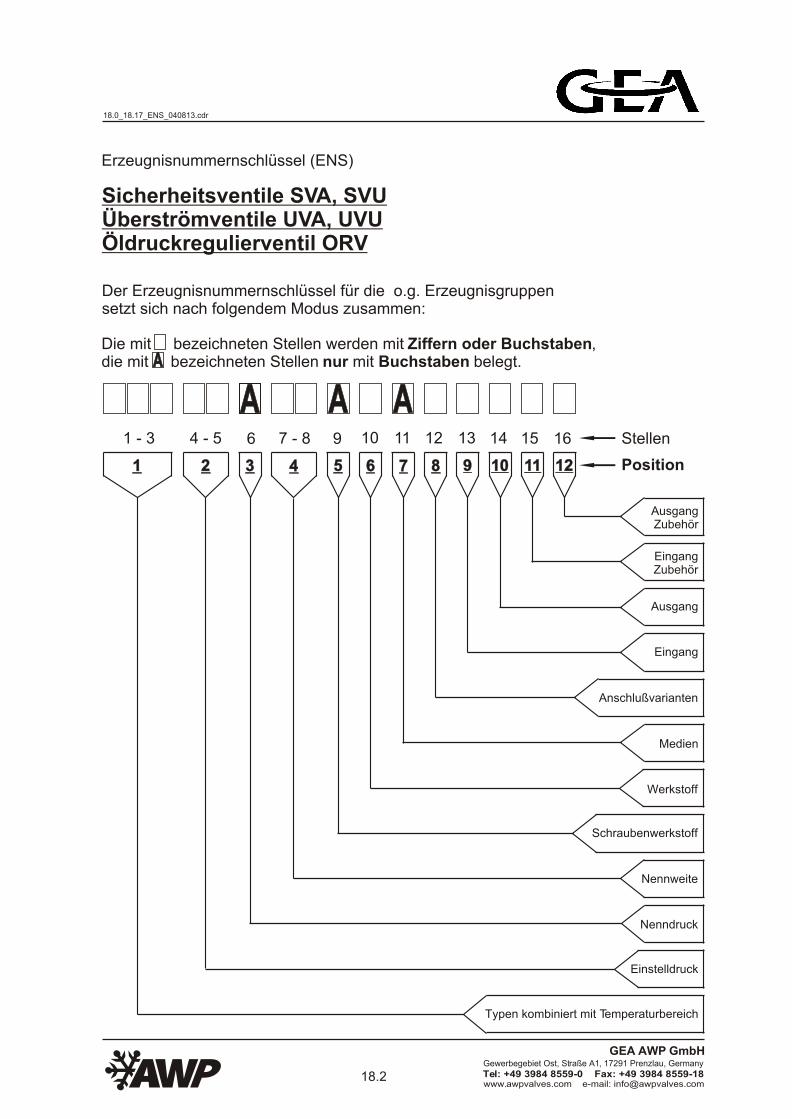
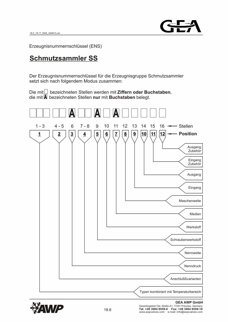
Erzeugnisnummernschlüssel (ENS)
Der Erzeugnisnummernschlüssel für die o.g. Erzeugnisgruppen setzt sich nach folgendem Modus zusammen:
Die mit bezeichneten Stellen werden mit Ziffern oder Buchstaben, die mit bezeichneten Stellen nur mit Buchstaben belegt.
AA AAAAAA
Stellen
Position
1 - 3 6 11109 1312 14 15 16
11 22 554433 66 8877 99 1010 1111 1212
AusgangZubehör
EingangZubehör
Ausgang
Eingang
Anschlußvarianten
Medien
Werkstoff
Nennweite
Nenndruck
Einstelldruck
Sicherheitsventile SVA, SVUÜberströmventile UVA, UVUÖldruckregulierventil ORV
7 - 84 - 5
Schraubenwerkstoff
Typen kombiniert mit Temperaturbereich
18.0_18.17_ENS_040813.cdr
18.2www.awpvalves.com e-mail: [email protected]
Gewerbegebiet Ost, Straße A1, 17291 Prenzlau, Germany
Tel: +49 3984 8559-0 Fax: +49 3984 8559-18
GEA AWP GmbH
Page 18
AA AAAAplace
position
1 - 3 6 11109 1312 14 15 16
11 22 554433 66 8877 99 1010 1111 1212
product identity code (ENS)
The placce will be defined with figures or letter,the place will be defined with letter only.AA
outletfittings
inletfittings
outlet
inlet
connections
medium
material
size
nominal pressure
set pressure
The product identity code for the product group as mentioned above is defined to the following mode:
safety valves SVA, SVUoverflow valves UVA, UVUoil pressure control valves ORV
7 - 84 - 5
screw material
types combined with temperature range
18.0_18.17_ENS_040813.cdr
18.3www.awpvalves.com e-mail: [email protected]
Gewerbegebiet Ost, Straße A1, 17291 Prenzlau, Germany
Tel: +49 3984 8559-0 Fax: +49 3984 8559-18
GEA AWP GmbH
Page 19
Nummernschlüssel [AWP-Code]
1 2 3 4 5 6 7 8 9 10 11 12 13 14 15 16
4 4 2 2 2 C 1 0 A 5 A 1 0 0 0 0Beispiel :
Code: Pos 1 bis 3 = Armaturentyp + Temperaturbereich
Code Typ Temperaturbereich Register AWP - Katalog
442444446447448432434
SVUB - Deckel geflanscht EckformSVUA - Deckel geflanscht EckformSVUB - Deckel geschraubt EckformSVUB - Deckel geschraubt EckformSVUA - Deckel geschraubt EckformSVAB - Deckel geschraubt EckformSVAA - Deckel geschraubt Eckform
-35°C bis +100°C-60°C bis +180°C-35°C bis +100°C-45°C bis +100°C-60°C bis +180°C-35°C bis +100°C-60°C bis +180°C
6.16.16.5 - 6.56.116.11
Code: Pos 4 bis 5 = EinstelldruckCode05 - 25
Code Pos :
SVU - Sicherheitsventil gegendruckunabhängigSVA - Sicherheitsventil gegendruckabhängig
Beispiel: 442 - SVUB = Deckel geflanscht Eckform, Temperaturbereich -35°C bis +100°C
05 - 25 bar
Beispiel: 22 = Einstelldruck 22 bar
Code: Pos 6 = max. BetriebsdruckCode
max. Betriebsdruck
C D
PS 25 PS 40Beispiel: C = max. Betriebsdruck 25 bar
Code: Pos 7 bis 8 = Nennweite
Code
DN
10 11 12 13 14 15 17
15/25 20/32 25/40 32/50 40/65 50/80 65/100
Beispiel: 10 = Nennweite DN 15/25
Code: Pos 9 = Deckelschraubenwerkstoff (wenn vorhanden)
Code A B C
Beispiel: A = Deckelschraubenwerkstoff 8.8
Schraubenwerkstoff 8.8 A2-70 5.6
Code: Pos 10 = Gehäusewerkstoff
Code 5 7 8
Beispiel: 5 = Gehäusewerkstoff 1.0305/1.0488
1.0305 = St35.8I1.0488 = TStE285
Code: Pos 11 = MediumCode Medium
Beispiel: C = Kältemedium ist NH3
ABCD
Code: Pos 12 = Anschußart
Beispiel: 1 = Flanschanschluß am Eingang und Ausgang
1.0488 = TStE2851.0356 = TTSt35
1.4301 = X5CrNi1810Gehäusewerkstoff
AWP - Sicherheitsventile
Beispiel: 0000 = DIN - Flansch mit Nut ohne Zubehör
Code: Pos 13 bis 16 = Spezifizierung der Anschlußenden in Abhängigkeit von Pos 12 Details bitte bei AWP nachfragen! Auswahl aus Standard:
= Anschweißende Reihe 1= Anschweißende ANSI Schedule 40
- Flansch mit Nut und Gegenflansche kpl.- Flansch mit Nut- Flansch 150lbs mit glatter Dichtleiste
Pos 12 = 0 dann 00001100
Pos 12 = 1 dann 0011EE008800
= DIN= AWP= ANSI
allgemeine Kältemittel und Kühlsohlen z.B. NH , CO , R134a, R410A, R22 usw.3 2
Propan, ButanPropylenHelium
Einstelldruck
Code01234567
Eingang
AEFLFLAESESEAESE
Ausgang
AEFLAEFLSEAESEFL
Code89ABCDEF
Eingang
FLSELELELEAELEFL
Ausgang
SELESELEAELEFLLE
= Anschweißende= Flanschanschluß= Schraubende= Lötende
AEFLSELE
442 + 444
Code
DN
07 08 10
08/10 10/10 15/15
446 - 448
Code
DN
08 10 11 12 13 14 15
10/20 15/25 20/25 25/40 32/40 40/65 50/65
432 + 434
18.0_18.17_ENS_040813.cdr
18.3.1www.awpvalves.com e-mail: [email protected]
Gewerbegebiet Ost, Straße A1, 17291 Prenzlau, Germany
Tel: +49 3984 8559-0 Fax: +49 3984 8559-18
GEA AWP GmbH
Page 20
1 2 3 4 5 6 7 8 9 10 11 12 13 14 15 16
4 4 2 2 2 C 1 0 A 5 A 1 0 0 0 0
Code type temperature range
442444446447448432434
SVUB - cover flanged angle typeSVUA - cover flanged angle typeSVUB - cover screwed angle typeSVUB - cover screwed angle typeSVUA - cover screwed angle typeSVAB - cover screwed angle typeSVAA - cover screwed angle type
-35°C to +100°C-60°C to +180°C-35°C to +100°C-45°C to +100°C-60°C to +180°C-35°C to +100°C-60°C to +180°C
6.16.16.5 -6.56.116.11
Code: Pos 4 bis 5 = set pressureCode05 - 25
Code Pos :
SVU - safety valve not depending on back pressureSVA - safety valve depending on back pressure
example: 442 - SVUB = cover flanged angle type, temperature range -35°C bis +100°C
05 - 25 bar
example: 22 = set pressure 22 bar
Code: Pos 6 = max. operating pressureCode
max. operating pressure
C D
PS 25 PS 40example: C = max. operating pressure 25 bar
Code: Pos 7 bis 8 = size
Code
DN
10 11 12 13 14 15 17
15/25 20/32 25/40 32/50 40/65 50/80 65/100
example: 10 = size DN 15/25
Code: Pos 9 = material of cover screws (if flanged cover)
Code A B C
example: A = material of cover screws 8.8
screw material 8.8 A2-70 5.6
Code: Pos 10 = body material
Code 5 7 8
example: 5 = body material 1.0305/1.0488
1.0305 = St35.8I1.0488 = TStE285
Code: Pos 11 = mediumCode
example: C = medium is NH3
ABCD
Code: Pos 12 = end connections
example: 1 = flange connection on inlet and outlet
1.0488 = TStE2851.0356 = TTSt35
1.4301 = X5CrNi1810body material
AWP - safety valves
set pressure
Code01234567
inlet
AEFLFLAESESEAESE
outlet
AEFLAEFLSEAESEFL
Code89ABCDEF
inlet
FLSELELELEAELEFL
outlet
SELESELEAELEFLLE
= welding ends= flange connection= screw ends= solder ends
AEFLSELE
442 + 444
Code
DN
07 08 10
08/10 10/10 15/15
446 - 448
Code
DN
08 10 11 12 13 14 15
10/20 15/25 20/25 25/40 32/40 40/65 50/65
432 + 434
identity code [AWP-code]
example :
register AWP - cataloge
mediumgeneral refrigerants and brines e.q. NH , CO , R134a, R410A, R22 and more3 2
propane, butanepropylenehelium
example: 0000 = welding end range 1 without fittings
= welding end range 1= welding end ANSI Schedule 40
choice of standard valves:
Pos 12 = 0 then 00001100
Pos 12 = 1 then - flange with groove and counterflanges cpl.- flange with groove- flange 150lbs with raised face
0011EE008800
= DIN= AWP= ANSI
Code: Pos 13 to 16 = specification of valve connection depending on Pos 12 details please request AWP !
Code: Pos 1 to 3 = valve type + temperature range
18.0_18.17_ENS_040813.cdr
18.3.2www.awpvalves.com e-mail: [email protected]
Gewerbegebiet Ost, Straße A1, 17291 Prenzlau, Germany
Tel: +49 3984 8559-0 Fax: +49 3984 8559-18
GEA AWP GmbH
Page 21
Nummernschlüssel [AWP-Code]
1 2 3 4 5 6 7 8 9 10 11 12 13 14 15 16
4 2 2 2 2 C 1 0 A 5 A 1 0 0 0 0Beispiel :
Code: Pos 1 bis 3 = Armaturentyp + Temperaturbereich
Code Typ Temperaturbereich Register AWP - Katalog
402412414416422424426
UVR - Deckel geflanscht EckformUVAA - Deckel geschraubt EckformUVAB - Deckel geschraubt EckformUVAB - Deckel geschraubt EckformUVUA - Deckel geschraubt EckformUVUB - Deckel geschraubt EckformUVUB - Deckel geschraubt Eckform
-60°C bis +180°C-60°C bis +180°C-35°C bis +100°C-45°C bis +100°C-60°C bis +180°C-35°C bis +100°C-45°C bis +100°C
-8.78.78.78.18.18.1
Code Pos :
UVU - Überströmventil gegendruckunabhängigUVA - Überströmventil gegendruckabhängigUVR - Überströmventil gegendruckabhängig, absperrbar
Beispiel: 422 - UVUA = Deckel geschraubt Eckform, Temperaturbereich -60°C bis +180°C
Code: Pos 7 bis 8 = Nennweite
Beispiel: 10 = Nennweite DN 15/25
Code: Pos 9 = Deckelschraubenwerkstoff (wenn vorhanden)
Code A B C
Beispiel: A = ohne Deckelschrauben
Schraubenwerkstoff 8.8 A2-70 5.6
Code: Pos 10 = Gehäusewerkstoff
Code 5 7 8
Beispiel: 5 = Gehäusewerkstoff 1.0305/1.0488
1.0305 = St35.8I1.0488 = TStE285
Code: Pos 11 = MediumCode Medium
Beispiel: C = Kältemedium ist NH3
ABCD
Code: Pos 12 = Anschußart
Beispiel: 1 = Flanschanschluß am Eingang und Ausgang
Code: Pos 6 = max. Betriebsdruck
Code
max. Betriebsdruck
C D
PS 25 PS 40Beispiel: C = max. Betriebsdruck 25 bar
1.0488 = TStE2851.0356 = TTSt35
1.4301 = X5CrNi1810Gehäusewerkstoff
AWP - Überströmventile
Beispiel: 0000 = DIN - Flansch mit Nut ohne Zubehör
Code: Pos 13 bis 16 = Spezifizierung der Anschlußenden in Abhängigkeit von Pos 12 Details bitte bei AWP nachfragen! Auswahl aus Standard:
= Anschweißende Reihe 1= Anschweißende ANSI Schedule 40
- Flansch mit Nut und Gegenflansche kpl.- Flansch mit Nut- Flansch 150lbs mit glatter Dichtleiste
Pos 12 = 0 dann 00001100
Pos 12 = 1 dann 0011EE008800
= DIN= AWP= ANSI
allgemeine Kältemittel und Kühlsohlen z.B. NH , CO , R134a, R410A, R22 usw.3 2
Propan, ButanPropylenHelium
Code: Pos 4 bis 5 = Einstelldruck
Code05 - 25 05 - 25 bar
Beispiel: 22 = Einstelldruck 22 bar
Einstelldruck
Code01234567
Eingang
AEFLFLAESESEAESE
Ausgang
AEFLAEFLSEAESEFL
Code89ABCDEF
Eingang
FLSELELELEAELEFL
Ausgang
SELESELEAELEFLLE
= Anschweißende= Flanschanschluß= Schraubende= Lötende
AEFLSELE
Code
DN
06 07 08 10 11 12 13
6 8 10 15 20 25 32
412414416
Code
DN
06 07 08 10
6 8 10 15
422424426
Code
DN
11 12
20 25402
18.0_18.17_ENS_040813.cdr
18.3.3www.awpvalves.com e-mail: [email protected]
Gewerbegebiet Ost, Straße A1, 17291 Prenzlau, Germany
Tel: +49 3984 8559-0 Fax: +49 3984 8559-18
GEA AWP GmbH
Page 22
example: 10 = size DN 15
Code: Pos 9 = material of cover screws (if flanged cover)
Code A B C
example: A = without cover screws
screw material 8.8 A2-70 5.6
Code: Pos 10 = body material
Code 5 7 8
example: 5 = body material 1.0305/1.0488
1.0305 = St35.8I1.0488 = TStE285
Code: Pos 11 = mediumCode
example: C = medium is NH3
ABCD
Code: Pos 12 = end connections
example: 1 = flange connection on inlet and outlet
1.0488 = TStE2851.0356 = TTSt35
1.4301 = X5CrNi1810body material
Code01234567
inlet
AEFLFLAESESEAESE
outlet
AEFLAEFLSEAESEFL
Code89ABCDEF
inlet
FLSELELELEAELEFL
outlet
SELESELEAELEFLLE
= welding ends= flange connection= screw ends= solder ends
AEFLSELE
mediumgeneral refrigerants and brines e.q. NH , CO , R134a, R410A, R22 and more3 2
propane, butanepropylenehelium
example: 0000 = welding end range 1 without fittings
= welding end range 1= welding end ANSI Schedule 40
choice of standard valves:
Pos 12 = 0 then 00001100
Pos 12 = 1 then - flange with groove and counterflanges cpl.- flange with groove- flange 150lbs with raised face
0011EE008800
= DIN= AWP= ANSI
Code: Pos 13 to 16 = specification of valve connection depending on Pos 12 details please request AWP !
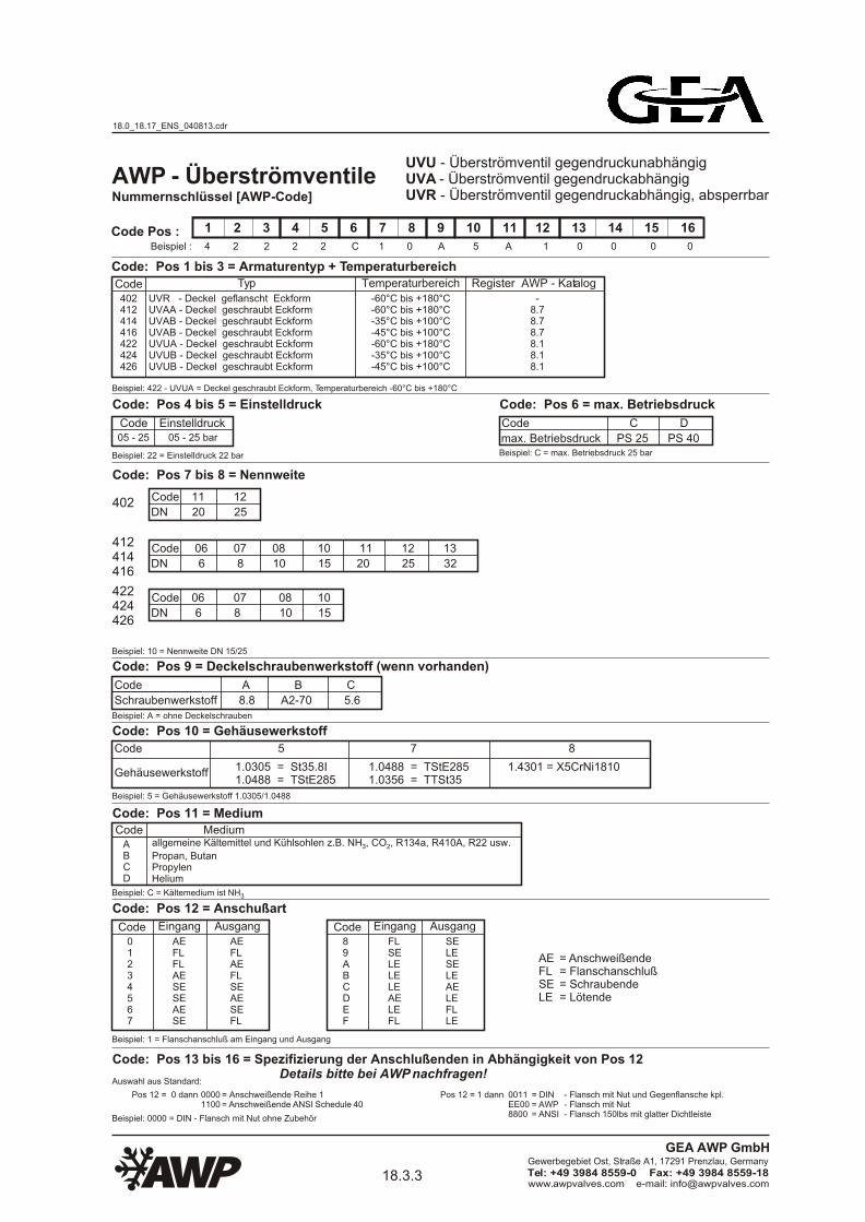
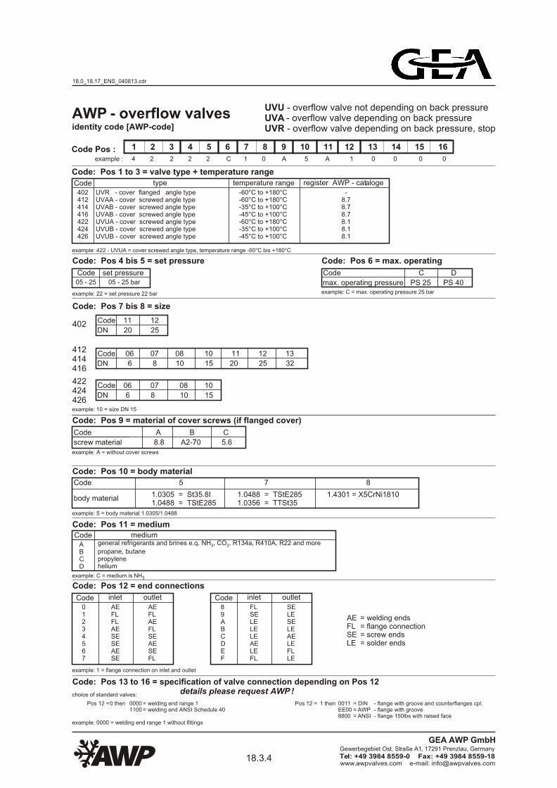
1 2 3 4 5 6 7 8 9 10 11 12 13 14 15 16
4 2 2 2 2 C 1 0 A 5 A 1 0 0 0 0
Code type402412414416422424426
UVR - cover flanged angle typeUVAA - cover screwed angle typeUVAB - cover screwed angle typeUVAB - cover screwed angle typeUVUA - cover screwed angle typeUVUB - cover screwed angle typeUVUB - cover screwed angle type
-60°C to +180°C-60°C to +180°C-35°C to +100°C-45°C to +100°C-60°C to +180°C-35°C to +100°C-45°C to +100°C
-8.78.78.78.18.18.1
Code Pos :
UVU - overflow valve not depending on back pressureUVA - overflow valve depending on back pressureUVR - overflow valve depending on back pressure, stop
example: 422 - UVUA = cover screwed angle type, temperature range -60°C bis +180°C
Code: Pos 7 bis 8 = size
Code: Pos 6 = max. operating
Code
max. operating pressure
C D
PS 25 PS 40example: C = max. operating pressure 25 bar
AWP - overflow valves
Code: Pos 4 bis 5 = set pressure
Code05 - 25 05 - 25 bar
example: 22 = set pressure 22 bar
set pressure
Code
DN
06 07 08 10 11 12 13
6 8 10 15 20 25 32
412414416
Code
DN
06 07 08 10
6 8 10 15
422424426
Code
DN
11 12
20 25402
identity code [AWP-code]
example :
Code: Pos 1 to 3 = valve type + temperature range
temperature range register AWP - cataloge
18.0_18.17_ENS_040813.cdr
18.3.4www.awpvalves.com e-mail: [email protected]
Gewerbegebiet Ost, Straße A1, 17291 Prenzlau, Germany
Tel: +49 3984 8559-0 Fax: +49 3984 8559-18
GEA AWP GmbH
Page 23
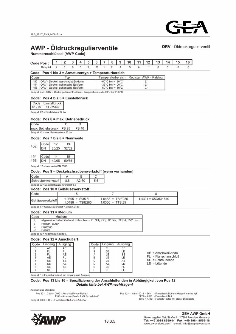
Nummernschlüssel [AWP-Code]
1 2 3 4 5 6 7 8 9 10 11 12 13 14 15 16
4 5 6 0 3 C 1 2 A 5 A 1 0 0 0 0Beispiel :
Code: Pos 1 bis 3 = Armaturentyp + Temperaturbereich
Code Typ Temperaturbereich Register AWP - Katalog
452454456
ORV - Deckel geschraubt EckformORV - Deckel geflanscht EckformORV - Deckel geflanscht Eckform
-60°C bis +180°C-35°C bis +100°C-60°C bis +180°C
9.19.19.1
Code Pos :
ORV - Öldruckregulierventil
Beispiel: 456 - ORV = Deckel geflanscht Eckform, Temperaturbereich -60°C bis +180°C
Code: Pos 7 bis 8 = Nennweite
Beispiel: 12 = Nennweite DN 25/25
Code: Pos 9 = Deckelschraubenwerkstoff (wenn vorhanden)
Code A B C
Beispiel: A = Deckelschraubenwerkstoff 8.8
Schraubenwerkstoff 8.8 A2-70 5.6
Code: Pos 10 = Gehäusewerkstoff
Code 5 7 8
Beispiel: 5 = Gehäusewerkstoff 1.0305/1.0488
1.0305 = St35.8I1.0488 = TStE285
Code: Pos 11 = MediumCode Medium
Beispiel: C = Kältemedium ist NH3
ABCD
Code: Pos 12 = Anschußart
Beispiel: 1 = Flanschanschluß am Eingang und Ausgang
Code: Pos 6 = max. Betriebsdruck
Code
max. Betriebsdruck
C D
PS 25 PS 40Beispiel: C = max. Betriebsdruck 25 bar
1.0488 = TStE2851.0356 = TTSt35
1.4301 = X5CrNi1810Gehäusewerkstoff
AWP - Öldruckregulierventile
Beispiel: 0000 = DIN - Flansch mit Nut ohne Zubehör
Code: Pos 13 bis 16 = Spezifizierung der Anschlußenden in Abhängigkeit von Pos 12 Details bitte bei AWP nachfragen!
Auswahl aus Standard:
= Anschweißende Reihe 1= Anschweißende ANSI Schedule 40
- Flansch mit Nut und Gegenflansche kpl.- Flansch mit Nut- Flansch 150lbs mit glatter Dichtleiste
Pos 12 = 0 dann 00001100
Pos 12 = 1 dann 0011EE008800
= DIN= AWP= ANSI
allgemeine Kältemittel und Kühlsohlen z.B. NH , CO , R134a, R410A, R22 usw.3 2
Propan, ButanPropylenHelium
Code: Pos 4 bis 5 = Einstelldruck
Code05 - 25 01 - 25 bar
Beispiel: 22 = Einstelldruck 22 bar
Einstelldruck
Code01234567
Eingang
AEFLFLAESESEAESE
Ausgang
AEFLAEFLSEAESEFL
Code89ABCDEF
Eingang
FLSELELELEAELEFL
Ausgang
SELESELEAELEFLLE
= Anschweißende= Flanschanschluß= Schraubende= Lötende
AEFLSELE
454456
Code
DN
12 13
25/25 32/32452
Code
DN
14 15
40/65 50/65
18.0_18.17_ENS_040813.cdr
18.3.5www.awpvalves.com e-mail: [email protected]
Gewerbegebiet Ost, Straße A1, 17291 Prenzlau, Germany
Tel: +49 3984 8559-0 Fax: +49 3984 8559-18
GEA AWP GmbH
Page 24
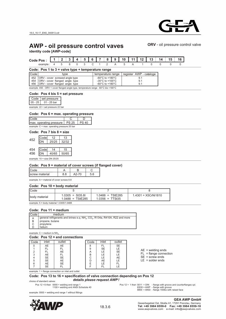
1 2 3 4 5 6 7 8 9 10 11 12 13 14 15 16
4 5 6 0 3 C 1 2 A 5 A 1 0 0 0 0
Code type452454456
ORV - cover screwed angle typeORV - cover flanged angle typeORV - cover flanged angle type
-60°C to +180°C-35°C to +100°C-60°C to +180°C
9.19.19.1
Code Pos :
ORV - oil pressure control valve
example: 456 - ORV = cover flanged angle type, temperature range -60°C bis +180°C
Code: Pos 7 bis 8 = size
example: 10 = size DN 25/25
Code: Pos 6 = max. operating pressure
Code
max. operating pressure
C D
PS 25 PS 40example: C = max. operating pressure 25 bar
AWP - oil pressure control vaves
Code: Pos 4 bis 5 = set pressure
Code05 - 25 01 - 25 bar
example: 22 = set pressure 22 bar
set pressure
454456
Code
DN
12 13
25/25 32/32452
Code
DN
14 15
40/65 50/65
temperature range register AWP - cataloge
Code: Pos 9 = material of cover screws (if flanged cover)
Code A B C
example: A = material of cover screws 8.8
screw material 8.8 A2-70 5.6
Code: Pos 10 = body material
Code 5 7 8
example: 5 = body material 1.0305/1.0488
1.0305 = St35.8I1.0488 = TStE285
Code: Pos 11 = mediumCode
example: C = medium is NH3
ABCD
Code: Pos 12 = end connections
example: 1 = flange connection on inlet and outlet
1.0488 = TStE2851.0356 = TTSt35
1.4301 = X5CrNi1810body material
Code01234567
inlet
AEFLFLAESESEAESE
outlet
AEFLAEFLSEAESEFL
Code89ABCDEF
inlet
FLSELELELEAELEFL
outlet
SELESELEAELEFLLE
= welding ends= flange connection= screw ends= solder ends
AEFLSELE
mediumgeneral refrigerants and brines e.q. NH , CO , R134a, R410A, R22 and more3 2
propane, butanepropylenehelium
example: 0000 = welding end range 1 without fittings
= welding end range 1= welding end ANSI Schedule 40
choice of standard valves:
Pos 12 = 0 then 00001100
Pos 12 = 1 then - flange with groove and counterflanges cpl.- flange with groove- flange 150lbs with raised face
0011EE008800
= DIN= AWP= ANSI
Code: Pos 13 to 16 = specification of valve connection depending on Pos 12 details please request AWP !
Code: Pos 1 to 3 = valve type + temperature range
identity code [AWP-code]
example :
18.0_18.17_ENS_040813.cdr
18.3.6www.awpvalves.com e-mail: [email protected]
Gewerbegebiet Ost, Straße A1, 17291 Prenzlau, Germany
Tel: +49 3984 8559-0 Fax: +49 3984 8559-18
GEA AWP GmbH
Page 25
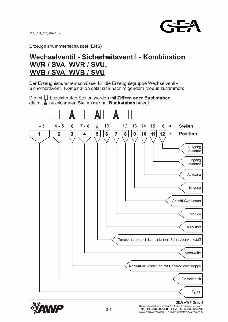
Erzeugnisnummernschlüssel (ENS)
Die mit bezeichneten Stellen werden mit Ziffern oder Buchstaben, die mit bezeichneten Stellen nur mit Buchstaben belegt.
AA AAAA
AA
Stellen
Position
1 - 3 6 11109 1312 14 15 16
11 22 554433 66 8877 99 1010 1111 1212
AusgangZubehör
EingangZubehör
Ausgang
Eingang
Anschlußvarianten
Medien
Werkstoff
Temperaturbereich kombiniert mit Schraubenwerkstoff
Nennweite
Nenndruck kombiniert mit Handrad oder Kappe
Einstelldruck
Typen
Wechselventil - Sicherheitsventil - KombinationWVR / SVA, WVR / SVU, WVB / SVA, WVB / SVU
Der Erzeugnisnummernschlüssel für die Erzeugnisgruppe Wechselventil-Sicherheitsventil-Kombination setzt sich nach folgendem Modus zusammen:
7 - 84 - 5
18.0_18.17_ENS_040813.cdr
18.4www.awpvalves.com e-mail: [email protected]
Gewerbegebiet Ost, Straße A1, 17291 Prenzlau, Germany
Tel: +49 3984 8559-0 Fax: +49 3984 8559-18
GEA AWP GmbH
Page 26
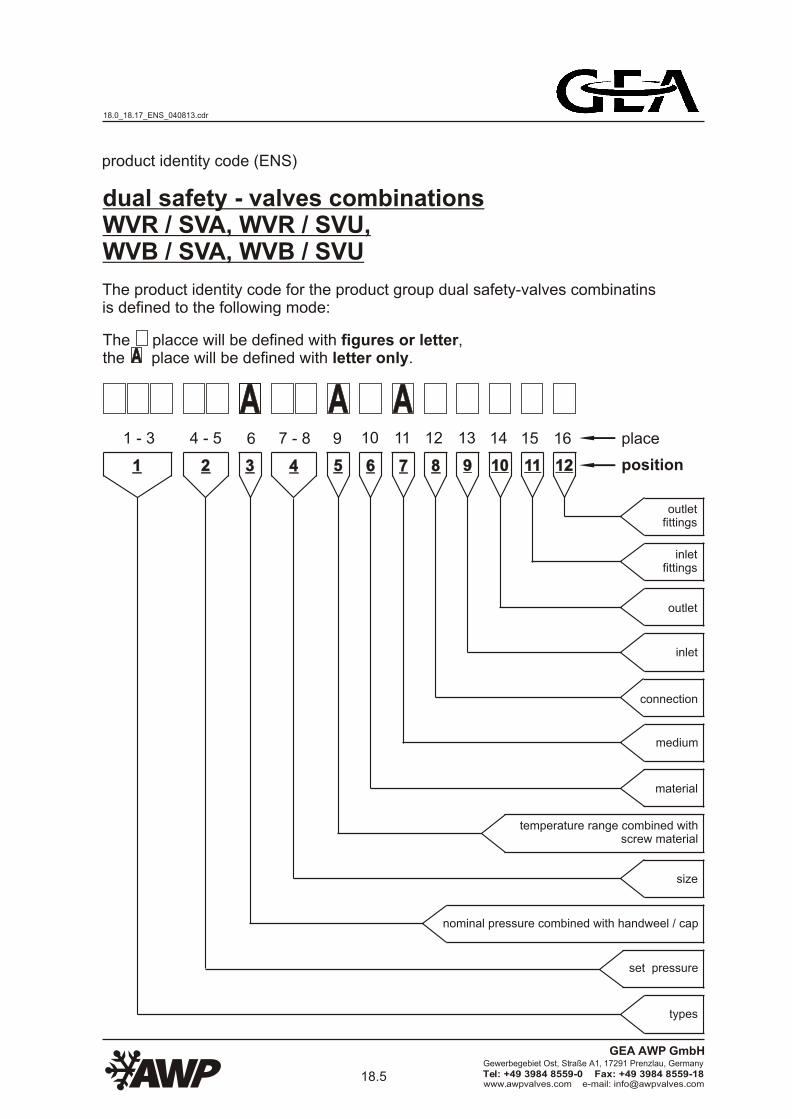
AA AAAAplace
position
1 - 3 6 11109 1312 14 15 16
11 22 554433 66 8877 99 1010 1111 1212
dual safety - valves combinations WVR / SVA, WVR / SVU, WVB / SVA, WVB / SVU
product identity code (ENS)
The product identity code for the product group dual safety-valves combinatinsis defined to the following mode:
The placce will be defined with figures or letter,the place will be defined with letter only.AA
outletfittings
inletfittings
outlet
inlet
connection
medium
material
temperature range combined withscrew material
size
nominal pressure combined with handweel / cap
set pressure
types
7 - 84 - 5
18.0_18.17_ENS_040813.cdr
18.5www.awpvalves.com e-mail: [email protected]
Gewerbegebiet Ost, Straße A1, 17291 Prenzlau, Germany
Tel: +49 3984 8559-0 Fax: +49 3984 8559-18
GEA AWP GmbH
Page 27
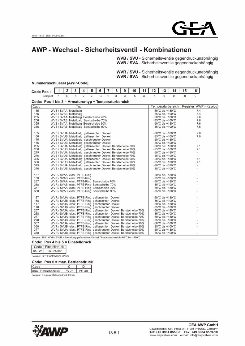
Nummernschlüssel [AWP-Code]
1 2 3 4 5 6 7 8 9 10 11 12 13 14 15 16
1 6 5 2 2 C 1 3 A 5 A 1 0 0 0 0Beispiel :
Code: Pos 1 bis 3 = Armaturentyp + Temperaturbereich
Code Typ Temperaturbereich Register AWP - Katalog
155156255256355356
165166175176265266275276365366375376
157158257258357358
167168177178267268277278367368377378
WVB / SVAA MetallbalgWVB / SVAB MetallbalgWVB / SVAA Metallbalg Berstscheibe 70%WVB / SVAB Metallbalg Berstscheibe 70%WVB / SVAA Metallbalg Berstscheibe 90%WVB / SVAB Metallbalg Berstscheibe 90%
-60°C bis +180°C-35°C bis +100°C-60°C bis +180°C-35°C bis +100°C-60°C bis +180°C-35°C bis +100°C
7.47.47.67.67.67.6
Code Pos :
WVB / SVU - Sicherheitsventile gegendruckunabhängigWVB / SVA - Sicherheitsventile gegendruckabhängig
WVR / SVU - Sicherheitsventile gegendruckunabhängigWVR / SVA - Sicherheitsventile gegendruckabhängig
Beispiel: 165 - WVB / SVUA = Metallbalg geflanschter Deckel, Temperaturbereich -60°C bis +180°C
AWP - Wechsel - Sicherheitsventil - Kombinationen
DeckelDeckelDeckelDeckelDeckel Berstscheibe 70%Deckel Berstscheibe 70%Deckel Berstscheibe 70%Deckel Berstscheibe 70%Deckel Berstscheibe 90%Deckel Berstscheibe 90%Deckel Berstscheibe 90%Deckel Berstscheibe 90%
-60°C bis +180°C-35°C bis +100°C-60°C bis +180°C-35°C bis +100°C-60°C bis +180°C-35°C bis +100°C-60°C bis +180°C-35°C bis +100°C-60°C bis +180°C-35°C bis +100°C-60°C bis +180°C-35°C bis +100°C
WVR / SVAA elast. PTFE-RingWVR / SVAB elast. PTFE-RingWVR / SVAA elast. PTFE-Ring Berstscheibe 70%WVR / SVAB elast. PTFE-Ring Berstscheibe 70%WVR / SVAA elast. PTFE-Ring Berstscheibe 90%WVR / SVAB elast. PTFE-Ring Berstscheibe 90%
-60°C bis +180°C-35°C bis +100°C-60°C bis +180°C-35°C bis +100°C-60°C bis +180°C-35°C bis +100°C
DeckelDeckelDeckelDeckelDeckel Berstscheibe 70%Deckel Berstscheibe 70%Deckel Berstscheibe 70%Deckel Berstscheibe 70%Deckel Berstscheibe 90%Deckel Berstscheibe 90%Deckel Berstscheibe 90%Deckel Berstscheibe 90%
-60°C bis +180°C-35°C bis +100°C-60°C bis +180°C-35°C bis +100°C-60°C bis +180°C-35°C bis +100°C-60°C bis +180°C-35°C bis +100°C-60°C bis +180°C-35°C bis +100°C-60°C bis +180°C-35°C bis +100°C
Code: Pos 4 bis 5 = EinstelldruckCode05 - 25 05 - 25 bar
Beispiel: 22 = Einstelldruck 22 bar
Einstelldruck
Code: Pos 6 = max. BetriebsdruckCode
max. Betriebsdruck
C D
PS 25 PS 40Beispiel: C = max. Betriebsdruck 25 bar
7.07.0--7.17.1--7.17.1--
------
------------
WVB / SVUA Metallbalg geflanschterWVB / SVUB Metallbalg geflanschterWVB / SVUA Metallbalg geschraubterWVB / SVUB Metallbalg geschraubterWVB / SVUA Metallbalg geflanschterWVB / SVUB Metallbalg geflanschterWVB / SVUA Metallbalg geschraubterWVB / SVUB Metallbalg geschraubterWVB / SVUA Metallbalg geflanschterWVB / SVUB Metallbalg geflanschterWVB / SVUA Metallbalg geschraubterWVB / SVUB Metallbalg geschraubter
WVR / SVUA elast. PTFE-Ring geflanschterWVR / SVUB elast. PTFE-Ring geflanschterWVR / SVUA elast. PTFE-Ring geschraubterWVR / SVUB elast. PTFE-Ring geschraubterWVR / SVUA elast. PTFE-Ring geflanschterWVR / SVUB elast. PTFE-Ring geflanschterWVR / SVUA elast. PTFE-Ring geschraubterWVR / SVUB elast. PTFE-Ring geschraubterWVR / SVUA elast. PTFE-Ring geflanschterWVR / SVUB elast. PTFE-Ring geflanschterWVR / SVUA elast. PTFE-Ring geschraubterWVR / SVUB elast. PTFE-Ring geschraubter
18.0_18.17_ENS_040813.cdr
18.5.1www.awpvalves.com e-mail: [email protected]
Gewerbegebiet Ost, Straße A1, 17291 Prenzlau, Germany
Tel: +49 3984 8559-0 Fax: +49 3984 8559-18
GEA AWP GmbH
Page 28
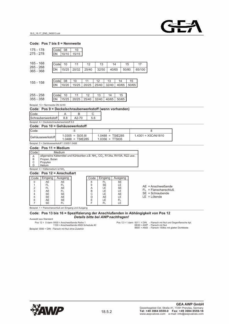
Code: Pos 7 bis 8 = Nennweite
Beispiel: 13 = Nennweite DN 32/40
Code: Pos 9 = Deckelschraubenwerkstoff (wenn vorhanden)
Code A B C
Beispiel: A = Deckelschraubenwerkstoff 8.8
Schraubenwerkstoff 8.8 A2-70 5.6
Code: Pos 10 = Gehäusewerkstoff
Code 5 7 8
Beispiel: 5 = Gehäusewerkstoff 1.0305/1.0488
1.0305 = St35.8I1.0488 = TStE285
Code: Pos 11 = MediumCode Medium
Beispiel: C = Kältemedium ist NH3
ABCD
Code: Pos 12 = Anschußart
Beispiel: 1 = Flanschanschluß am Eingang und Ausgang
1.0488 = TStE2851.0356 = TTSt35
1.4301 = X5CrNi1810Gehäusewerkstoff
Beispiel: 0000 = DIN - Flansch mit Nut ohne Zubehör
Code: Pos 13 bis 16 = Spezifizierung der Anschlußenden in Abhängigkeit von Pos 12 Details bitte bei AWP nachfragen! Auswahl aus Standard:
= Anschweißende Reihe 1= Anschweißende ANSI Schedule 40
- Flansch mit Nut und Gegenflansche kpl.- Flansch mit Nut- Flansch 150lbs mit glatter Dichtleiste
Pos 12 = 0 dann 00001100
Pos 12 = 1 dann 0011EE008800
= DIN= AWP= ANSI
allgemeine Kältemittel und Kühlsohlen z.B. NH , CO , R134a, R410A, R22 usw.3 2
Propan, ButanPropylenHelium
Code01234567
Eingang
AEFLFLAESESEAESE
Ausgang
AEFLAEFLSEAESEFL
Code89ABCDEF
Eingang
FLSELELELEAELEFL
Ausgang
SELESELEAELEFLLE
= Anschweißende= Flanschanschluß= Schraubende= Lötende
AEFLSELE
Code
DN
08 10
10/10 15/15
175 - 178275 - 278
Code
DN
08 10 11 12 13 14 15
10/20 15/25 20/25 25/40 32/40 40/65 50/65155 - 158
Code
DN
10 11 12 13 14 15
15/25 20/25 25/40 32/40 40/65 50/65
255 - 258355 - 358
Code
DN
10 11 12 13 14 15 17
15/25 20/32 25/40 32/50 40/65 50/80 65/100
165 - 168265 - 268365 - 368
18.0_18.17_ENS_040813.cdr
18.5.2www.awpvalves.com e-mail: [email protected]
Gewerbegebiet Ost, Straße A1, 17291 Prenzlau, Germany
Tel: +49 3984 8559-0 Fax: +49 3984 8559-18
GEA AWP GmbH
Page 29
1 2 3 4 5 6 7 8 9 10 11 12 13 14 15 16
1 6 5 2 2 C 1 3 A 5 A 1 0 0 0 0
Code type temperature range
155156255256355356
165166175176265266275276365366375376
157158257258357358
167168177178267268277278367368377378
WVB / SVAA metal bellowWVB / SVAB metal bellowWVB / SVAA metal bellow bursting disc 70%WVB / SVAB metal bellow bursting disc 70%WVB / SVAA metal bellow bursting disc 90%WVB / SVAB metal bellow bursting disc 90%
-60°C to +180°C-35°C to +100°C-60°C to +180°C-35°C to +100°C-60°C to +180°C-35°C to +100°C
7.47.47.67.67.67.6
Code Pos :
WVB / SVU - safety valves not depending on back pressureWVB / SVA - safety valves depending on back pressure
WVR / SVU - safety valves not depending on back pressureWVR / SVA - safety valves depending on back pressure
example: 165 - WVB / SVUA = metal bellow flanged cover, temperature range -60°C to +180°C
AWP - dual - safety valve - combinations
covercovercovercovercover bursting disc 70%cover bursting disc 70%cover bursting disc 70%cover bursting disc 70%cover bursting disc 90%cover bursting disc 90%cover bursting disc 90%cover bursting disc 90%
-60°C to +180°C-35°C to +100°C-60°C to +180°C-35°C to +100°C-60°C to +180°C-35°C to +100°C-60°C to +180°C-35°C to +100°C-60°C to +180°C-35°C to +100°C-60°C to +180°C-35°C to +100°C
WVR / SVAA elastic PTFE-ringWVR / SVAB elastic PTFE-ringWVR / SVAA elastic PTFE-ring bursting disc 70%WVR / SVAB elastic PTFE-ring bursting disc 70%WVR / SVAA elastic PTFE-ring bursting disc 90%WVR / SVAB elastic PTFE-ring bursting disc 90%
-60°C to +180°C-35°C to +100°C-60°C to +180°C-35°C to +100°C-60°C to +180°C-35°C to +100°C
covercovercovercovercover bursting disc 70%cover bursting disc 70%cover bursting disc 70%cover bursting disc 70%cover bursting disc 90%cover bursting disc 90%cover bursting disc 90%cover bursting disc 90%
-60°C to +180°C-35°C to +100°C-60°C to +180°C-35°C to +100°C-60°C to +180°C-35°C to +100°C-60°C to +180°C-35°C to +100°C-60°C to +180°C-35°C to +100°C-60°C to +180°C-35°C to +100°C
7.07.0--7.17.1--7.17.1--
------
------------
identity code [AWP-code]
example :
Code: Pos 1 to 3 = valve type + temperature range
Code: Pos 6 = max. operating pressure
Code
max. operating pressure
C D
PS 25 PS 40example: C = max. operating pressure 25 bar
Code: Pos 4 bis 5 = set pressure
Code05 - 25 01 - 25 bar
example: 22 = set pressure 22 bar
set pressure
WVB / SVUA metal bellow flangedWVB / SVUB metal bellow flangedWVB / SVUA metal bellow screwedWVB / SVUB metal bellow screwedWVB / SVUA metal bellow flangedWVB / SVUB metal bellow flangedWVB / SVUA metal bellow screwedWVB / SVUB metal bellow screwedWVB / SVUA metal bellow flangedWVB / SVUB metal bellow flangedWVB / SVUA metal bellow screwedWVB / SVUB metal bellow screwed
WVR / SVUA elastic PTFE-ring flangedWVR / SVUB elastic PTFE-ring flangedWVR / SVUA elastic PTFE-ring screwedWVR / SVUB elastic PTFE-ring screwedWVR / SVUA elastic PTFE-ring flangedWVR / SVUB elastic PTFE-ring flangedWVR / SVUA elastic PTFE-ring screwedWVR / SVUB elastic PTFE-ring screwedWVR / SVUA elastic PTFE-ring flangedWVR / SVUB elastic PTFE-ring flangedWVR / SVUA elastic PTFE-ring screwedWVR / SVUB elastic PTFE-ring screwed
register AWP - cataloge
18.0_18.17_ENS_040813.cdr
18.5.3www.awpvalves.com e-mail: [email protected]
Gewerbegebiet Ost, Straße A1, 17291 Prenzlau, Germany
Tel: +49 3984 8559-0 Fax: +49 3984 8559-18
GEA AWP GmbH
Page 30
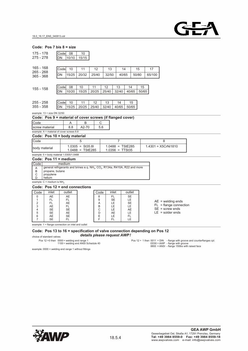
Code: Pos 7 bis 8 = size
example: 13 = size DN 32/50
Code
DN
08 10
10/10 15/15
175 - 178275 - 278
Code
DN
08 10 11 12 13 14 15
10/20 15/25 20/25 25/40 32/40 40/65 50/65155 - 158
Code
DN
10 11 12 13 14 15
15/25 20/25 25/40 32/40 40/65 50/65
255 - 258355 - 358
Code
DN
10 11 12 13 14 15 17
15/25 20/32 25/40 32/50 40/65 50/80 65/100
165 - 168265 - 268365 - 368
Code: Pos 9 = material of cover screws (if flanged cover)
Code A B C
example: A = material of cover screws 8.8
screw material 8.8 A2-70 5.6
Code: Pos 10 = body material
Code 5 7 8
example: 5 = body material 1.0305/1.0488
1.0305 = St35.8I1.0488 = TStE285
Code: Pos 11 = mediumCode
example: C = medium is NH3
ABCD
Code: Pos 12 = end connections
example: 1 = flange connection on inlet and outlet
1.0488 = TStE2851.0356 = TTSt35
1.4301 = X5CrNi1810body material
Code01234567
inlet
AEFLFLAESESEAESE
outlet
AEFLAEFLSEAESEFL
Code89ABCDEF
inlet
FLSELELELEAELEFL
outlet
SELESELEAELEFLLE
= welding ends= flange connection= screw ends= solder ends
AEFLSELE
mediumgeneral refrigerants and brines e.q. NH , CO , R134a, R410A, R22 and more3 2
propane, butanepropylenehelium
example: 0000 = welding end range 1 without fittings
= welding end range 1= welding end ANSI Schedule 40
choice of standard valves:
Pos 12 = 0 then 00001100
Pos 12 = 1 then - flange with groove and counterflanges cpl.- flange with groove- flange 150lbs with raised face
0011EE008800
= DIN= AWP= ANSI
Code: Pos 13 to 16 = specification of valve connection depending on Pos 12 details please request AWP !
18.0_18.17_ENS_040813.cdr
18.5.4www.awpvalves.com e-mail: [email protected]
Gewerbegebiet Ost, Straße A1, 17291 Prenzlau, Germany
Tel: +49 3984 8559-0 Fax: +49 3984 8559-18
GEA AWP GmbH
Page 31
Erzeugnisnummernschlüssel (ENS)
Der Erzeugnisnummernschlüssel für die Erzeugnisgruppe Schmutzsammlersetzt sich nach folgendem Modus zusammen:
Die mit bezeichneten Stellen werden mit Ziffern oder Buchstaben, die mit bezeichneten Stellen nur mit Buchstaben belegt.
AA AAAA
AA
Stellen
Position
1 - 3 6 11109 1312 14 15 16
11 22 554433 66 8877 99 1010 1111 1212
AusgangZubehör
EingangZubehör
Ausgang
Eingang
Maschenweite
Medien
Werkstoff
Nennweite
Nenndruck
Anschlußßvarianten
Schmutzsammler SS
7 - 84 - 5
Schraubenwerkstoff
Typen kombiniert mit Temperaturbereich
18.0_18.17_ENS_040813.cdr
18.6www.awpvalves.com e-mail: [email protected]
Gewerbegebiet Ost, Straße A1, 17291 Prenzlau, Germany
Tel: +49 3984 8559-0 Fax: +49 3984 8559-18
GEA AWP GmbH
Page 32
AA AAAAplace
position
1 - 3 6 11109 1312 14 15 16
11 22 554433 66 8877 99 1010 1111 1212
strainers SS
product identity code (ENS)
The product identity code for the product group strainersis defined to the following mode:
The placce will be defined with figures or letter,the place will be defined with letter only.AA
outletfittings
inletfittings
outlet
inlet
mash
medium
material
size
nominal pressure
connections
7 - 84 - 5
screw material
types combined with temperature range
18.0_18.17_ENS_040813.cdr
18.7www.awpvalves.com e-mail: [email protected]
Gewerbegebiet Ost, Straße A1, 17291 Prenzlau, Germany
Tel: +49 3984 8559-0 Fax: +49 3984 8559-18
GEA AWP GmbH
Page 33
AWP - SchmutzsammlerNummernschlüssel [AWP-Code]
1 2 3 4 5 6 7 8 9 10 11 12 13 14 15 16
5 2 3 0 0 C 1 9 A 5 A 3 0 0 0 0Beispiel :
Code: Pos 1 bis 3 = Armaturentyp + Temperaturbereich
Code Typ Temperaturbereich Register AWP - Katalog
523524
SS - Deckel geflanscht DurchgangsformSS - Deckel geflanscht Eckform
-60°C bis +150°C-60°C bis +150°C
12.1112.15
Code: Pos 4 bis 5 = AnschlußartCode
0010202122303132
80818283849091929394
Code Pos :
SS - Schmutzsammler
Beispiel: 523 - SS = Deckel geflanscht Durchgangsform, Temperaturbereich -60°C bis +150°C
Eingang
AEAEFLFLAEFLFLAE
Ausgang
AEAEFLAEFLFLAEFL
Code Eingang
LEAELELEFLLEAELELEFL
Ausgang
LELEAEFLLELELEAEFLLE
Beispiel: 00 = Anschweißende am Eingang und Ausgang
Code: Pos 6 = max. BetriebsdruckCode
max. Betriebsdruck
A B C D F
PS 10 PS 16 PS 25 PS 40 PS 63Beispiel: C = max. Betriebsdruck 25 bar
Code: Pos 7 bis 8 = NennweiteCode
DN
06 07 08 10 11 12 13 14 15 17 18 19 20 21 23
6 8 10 15 20 25 32 40 50 65 80 100 125 150 200
Beispiel: 19 = Nennweite DN 100
Code: Pos 9 = Deckelschraubenwerkstoff (wenn vorhanden)
Code A B C
Beispiel: A = Deckelschraubenwerkstoff 8.8
Schraubenwerkstoff 8.8 A2-70 5.6
Code: Pos 10 = Gehäusewerkstoff
Code 5 7 8
Beispiel: 5 = Gehäusewerkstoff 1.0305/1.0488
1.0305 = St35.8I1.0488 = TStE285
Code: Pos 11 = MediumCode Medium
Beispiel: C = Kältemedium ist NH3
ABCD
Code: Pos 12 = Maschenweite
Beispiel: 3 = Maschenweite 500 µm
1.0488 = TStE2851.0356 = TTSt35
1.4301 = X5CrNi1810Gehäusewerkstoff
Code
Maschenweite in µm
2 3 4 5 6 7 8 9 A B C D
1000 500 200 150 135 100 80 63 40 25 120 250
Beispiel: 0000 = Anschweißende Reihe 1 ohne Zubehör
Code: Pos 13 bis 16 = Spezifizierung der Anschlußenden in Abhängigkeit von Pos 4 bis 5 Details bitte bei AWP nachfragen! Auswahl aus Standard:
= Anschweißende Reihe 1= Anschweißende ANSI Schedule 40
- Flansch mit Nut und Gegenflansche kpl.- Flansch mit Nut- Flansch 150lbs mit glatter Dichtleiste
Pos 4 + 5 = 00 oder 10 dann 00001100
Pos 4 + 5 = 20 oder 30 dann 0011EE008800
= DIN= AWP= ANSI
= Anschweißende= Flanschanschluß= Lötende
AEFLLE
allgemeine Kältemittel und Kühlsohlen z.B. NH , CO , R134a, R410A, R22 usw.3 2
Propan, ButanPropylenHelium
18.0_18.17_ENS_040813.cdr
18.7.1www.awpvalves.com e-mail: [email protected]
Gewerbegebiet Ost, Straße A1, 17291 Prenzlau, Germany
Tel: +49 3984 8559-0 Fax: +49 3984 8559-18
GEA AWP GmbH
Page 34
AWP - strainer
1 2 3 4 5 6 7 8 9 10 11 12 13 14 15 16
5 2 3 0 0 C 1 9 A 5 A 3 0 0 0 0
Code523524
-60°C to +150°C-60°C to +150°C
12.1112.15
Code0010202122303132
80818283849091929394
Code Pos :
SS - strainer
AEAEFLFLAEFLFLAE
AEAEFLAEFLFLAEFL
CodeLEAELELEFLLEAELELEFL
LELEAEFLLELELEAEFLLE
Code
DN
06 07 08 10 11 12 13 14 15 17 18 19 20 21 23
6 8 10 15 20 25 32 40 50 65 80 100 125 150 200
Code: Pos 12 = Maschenweite
example: 3 = mesh 500 µm
Code
mesh in µm
2 3 4 5 6 7 8 9 A B C D
1000 500 200 150 135 100 80 63 40 25 120 250
example: 0000 = welding end range 1 without fittings
= welding end range 1= welding end ANSI Schedule 40
- flange with groove and counterflanges cpl.- flange with groove- flange 150lbs with raised face
choice of standard valves:
Pos 4 + 5 = 00 or 10 then 00001100
Pos 4 + 5 = 20 or 30 then 0011EE008800
= DIN= AWP= ANSI
Code: Pos 13 to 16 = specification of valve connection depending on Pos 4 to 5 details please request AWP !
= welding end= flange connection= solder end
AEFLLE
Code: Pos 4 to 5 = end connections
inlet outlet inlet outlet
Code: Pos 6 = max. operating pressureCode
max. operating pressure
A B C D F
PS 10 PS 16 PS 25 PS 40 PS 63example: C = max. operating pressure 25 bar
Code: Pos 7 to 8 = size
example: 19 = size DN 100
Code: Pos 9 = material of cover screws (if flanged cover)
Code A B C
example: A = material of cover screws 8.8
screw material 8.8 A2-70 5.6
Code: Pos 10 = body material
Code 5 7 8
example: 5 = body material 1.0305/1.0488
1.0305 = St35.8I1.0488 = TStE285
1.0488 = TStE2851.0356 = TTSt35
1.4301 = X5CrNi1810body material
identity code [AWP-code]
example :
example: 523 - SS = cover flanged globe type, temperature range -60°C to +150°C
SS - cover flanged globe typeSS - cover flanged angle type
typ temperature range register AWP - cataloge
Code: Pos 1 to 3 = valve type + temperature range
example: 00 = welding ends on inlet and outlet
Code: Pos 11 = mediumCode medium
example: C = medium is NH3
general refrigerants and brines e.q. NH , CO , R134a, R410A, R22 and more3 2
propane, butanepropylenehelium
ABCD
18.0_18.17_ENS_040813.cdr
18.7.2www.awpvalves.com e-mail: [email protected]
Gewerbegebiet Ost, Straße A1, 17291 Prenzlau, Germany
Tel: +49 3984 8559-0 Fax: +49 3984 8559-18
GEA AWP GmbH
Page 35
Erzeugnisnummernschlüssel (ENS)
Ölfilter OF
Der Erzeugnisnummernschlüssel für die Erzeugnisgruppe Ölfiltersetzt sich nach folgendem Modus zusammen:
Die mit bezeichneten Stellen werden mit Ziffern oder Buchstaben, die mit bezeichneten Stellen nur mit Buchstaben belegt.
AA AAAA
AA
Stellen
Position
1 - 3 6 11109 1312 14 15 16
11 22 554433 66 8877 99 1010 1111 1212
AusgangZubehör
EingangZubehör
Ausgang
Eingang
Filtergewebe
Medien
Werkstoff
Schraubenwerkstoff
Nennweite
Nenndruck
Anschlußvarianten
Typen, Durchflußrichtung
7 - 84 - 5
18.0_18.17_ENS_040813.cdr
18.8www.awpvalves.com e-mail: [email protected]
Gewerbegebiet Ost, Straße A1, 17291 Prenzlau, Germany
Tel: +49 3984 8559-0 Fax: +49 3984 8559-18
GEA AWP GmbH
Page 36
oil filter OF
AA AAAA1 - 3 6 11109 1312 14 15 16
11 22 554433 66 8877 99 1010 1111 1212
filter material / fineness
connecions
types, flow direction
The placce will be defined with figures or letter,the place will be defined with letter only.AA
place
position
outletfitings
inletfittings
outlet
inlet
medium
material
screw material
size
nominal pressure
The product identity code for the product group oil filteris defined to the following mode:
product identity code (ENS)
7 - 84 - 5
18.0_18.17_ENS_040813.cdr
18.9www.awpvalves.com e-mail: [email protected]
Gewerbegebiet Ost, Straße A1, 17291 Prenzlau, Germany
Tel: +49 3984 8559-0 Fax: +49 3984 8559-18
GEA AWP GmbH
Page 37
Erzeugnisnummernschlüssel (ENS)
Doppelölfilter DOF
Der Erzeugnisnummernschlüssel für die Erzeugnisgruppe Doppelölfiltersetzt sich nach folgendem Modus zusammen:
Die mit bezeichneten Stellen werden mit Ziffern oder Buchstaben, die mit bezeichneten Stellen nur mit Buchstaben belegt.
AA AAAA
AA
Stellen
Position
1 - 3 6 11109 1312 14 15 16
11 22 554433 66 8877 99 1010 1111 1212
AusgangZubehör
EingangZubehör
Ausgang
Eingang
Filtergewebe
Medien
Werkstoff
Nennweite
Nenndruck
Anschlußvarianten, Durchflußrichtung
Typen
7 - 84 - 5
Schraubenwerkstoff
18.0_18.17_ENS_040813.cdr
18.10www.awpvalves.com e-mail: [email protected]
Gewerbegebiet Ost, Straße A1, 17291 Prenzlau, Germany
Tel: +49 3984 8559-0 Fax: +49 3984 8559-18
GEA AWP GmbH
Page 38
double oil filter DOF
AA AAAA1 - 3 6 11109 1312 14 15 16
11 22 554433 66 8877 99 1010 1111 1212
connecions, flow direction
types
The product identity code for the product group double oil filteris defined to the following mode:
The placce will be defined with figures or letter,the place will be defined with letter only.AA
place
position
outletfitings
inletfittings
outlet
inlet
medium
material
size
nominal pressure
product identity code (ENS)
filter material / fineness
7 - 84 - 5
screw material
18.0_18.17_ENS_040813.cdr
18.11www.awpvalves.com e-mail: [email protected]
Gewerbegebiet Ost, Straße A1, 17291 Prenzlau, Germany
Tel: +49 3984 8559-0 Fax: +49 3984 8559-18
GEA AWP GmbH
Page 39
Erzeugnisnummernschlüssel (ENS)
Filtertrockner FT
Der Erzeugnisnummernschlüssel für die Erzeugnisgruppe Filtertrocknersetzt sich nach folgendem Modus zusammen:
Die mit bezeichneten Stellen werden mit Ziffern oder Buchstaben, die mit bezeichneten Stellen nur mit Buchstaben belegt.
AA AAAA
AA
Stellen
Position
1 - 3 6 11109 1312 14 15 16
11 22 554433 66 8877 99 1010 1111 1212
AusgangZubehör
EingangZubehör
Ausgang
Eingang
Elementeanzahl
Medien
Werkstoff
Nennweite
Nenndruck
Anschlußvarianten
Typen
7 - 84 - 5
Schraubenwerkstoff
18.0_18.17_ENS_040813.cdr
18.12www.awpvalves.com e-mail: [email protected]
Gewerbegebiet Ost, Straße A1, 17291 Prenzlau, Germany
Tel: +49 3984 8559-0 Fax: +49 3984 8559-18
GEA AWP GmbH
Page 40
filter drier FT
AA AAAA1 - 3 6 11109 1312 14 15 16
11 22 554433 66 8877 99 1010 1111 1212
quantity of elements
connecions
types
The product identity code for the product group filter drieris defined to the following mode:
The placce will be defined with figures or letter,the place will be defined with letter only.AA
place
position
outletfitings
inletfittings
outlet
inlet
medium
material
size
nominal pressure
product identity code (ENS)
7 - 84 - 5
screw material
18.0_18.17_ENS_040813.cdr
18.13www.awpvalves.com e-mail: [email protected]
Gewerbegebiet Ost, Straße A1, 17291 Prenzlau, Germany
Tel: +49 3984 8559-0 Fax: +49 3984 8559-18
GEA AWP GmbH
Page 41
Erzeugnisnummernschlüssel (ENS)
Die mit bezeichneten Stellen werden mit Ziffern oder Buchstaben, die mit bezeichneten Stellen nur mit Buchstaben belegt.AA
Stellen
Position11 665544 77 9988 1010 1111 1212 1313
AusgangZubehör
Zubehör EingangÖlabscheider
Zubehör EingangÖlkühler
EingangÖlabscheider
Anschlußvarianten
Medien
Werkstoff
Temperaturbereich
Nennweite
Nenndruck kombiniert mit Schraubenwerkstoff
Ausgang
Typen
AA AAAA
3322
1 - 3 7 - 84 5 6 11109 1312 14 15 16
EingangÖlkühler
Temperaturregler TR
Der Erzeugnisnummernschlüssel für die Erzeugnisgruppe Temperaturregler setzt sich nach folgendem Modus zusammen:
18.0_18.17_ENS_040813.cdr
18.14www.awpvalves.com e-mail: [email protected]
Gewerbegebiet Ost, Straße A1, 17291 Prenzlau, Germany
Tel: +49 3984 8559-0 Fax: +49 3984 8559-18
GEA AWP GmbH
Page 42
place
position11 665544 77 9988 1010 1111 1212 1313
AA AAAA
3322
1 - 3 7 - 84 5 6 11109 1312 14 15 16
product identity code (ENS)
thermostatic 3 - way valve TR
The placce will be defined with figures or letter,the place will be defined with letter only.AA
The product identity code for the product group thermostatic 3 - way valveis defined to the following mode:
outlet fittings
inlet fittingsoil separator
inlet fittingsoil cooler
inletoil separator
inletoil cooler
medium
material
temperature range
size
nominal pressure combined with screw material
outlet
connections
types
18.0_18.17_ENS_040813.cdr
18.15www.awpvalves.com e-mail: [email protected]
Gewerbegebiet Ost, Straße A1, 17291 Prenzlau, Germany
Tel: +49 3984 8559-0 Fax: +49 3984 8559-18
GEA AWP GmbH
Page 45
Gegenüberstellung Erzeugnisnummern alt - neucomparison product identity old - new
26303
26343
26333
26323
26341
26331
26321
26301
alte Typ - Nr.
previous valve type-no.
Absperrventile AVB Metallbalg ( alt )shut off valve AVB metal bellow ( previous )
neue Typ - Nr.
new valve type - no.
16332
16331
16330
16322
16321
16320
16310
16300
26403
26443
26433
26423
26441
26431
26421
26401
16432
16431
16430
16422
16421
16420
16410
16400
18.40www.awpvalves.com e-mail: [email protected]
Gewerbegebiet Ost, Straße A1, 17291 Prenzlau, Germany
Tel: +49 3984 8559-0 Fax: +49 3984 8559-18
GEA AWP GmbH
Page 46
26484
26334
26332
26324
26322
26304
26302
26482
alte Typ - Nr.
previous valve type-no.
Absperrventile AVR mit PTFE - Ring ( alt )shut off valve AVR with PTFE - ring ( previous )
neue Typ - Nr.
new valve type - no.
26331
26321
26330
26320
26310
26300
26490
26480
26344
26424
26422
26404
26402
26384
26382
26342
26444
26442
26434
26432
26430
26420
26410
26400
26390
26380
26332
26322
26432
26422
26431
26421
34324
34322
34304
34302
36330
36320
36310
36300
34334
34384
34382
34374
34372
34344
34342
34332
36390
36380
36370
36360
36332
36322
36331
36321
34373
18.41www.awpvalves.com e-mail: [email protected]
Gewerbegebiet Ost, Straße A1, 17291 Prenzlau, Germany
Tel: +49 3984 8559-0 Fax: +49 3984 8559-18
GEA AWP GmbH
Page 47
34404
34444
34442
34434
34432
34424
34422
34402
alte Typ - Nr.
previous valve type-no.
Absperrventile AVR mit PTFE - Ring ( alt )shut off valve AVR with PTFE - ring ( previous )
neue Typ - Nr.
new valve type - no.
36432
36422
36431
36421
36430
36420
36410
36400
34474
34484
34482
34472
36490
36480
36470
36460
36324
36322
36304
36302
36130
36120
36110
36100
36334
36384
36382
36374
36372
36344
36342
36332
36190
36180
36170
36160
36132
36122
36131
36121
36373
36424
36422
36404
36402
36230
36220
36210
36200
36434
36484
36482
36474
36472
36444
36442
36432
36290
36280
36270
36260
36232
36222
36231
36221
36473
34473
18.42www.awpvalves.com e-mail: [email protected]
Gewerbegebiet Ost, Straße A1, 17291 Prenzlau, Germany
Tel: +49 3984 8559-0 Fax: +49 3984 8559-18
GEA AWP GmbH
Page 48
26604
26644
26642
26634
26632
26624
26622
26602
alte Typ - Nr.
previous valve type-no.
Regelventile HRAR mit PTFE - Ring ( alt )regulating valve HRAR with PTFE - ring ( previous )
neue Typ - Nr.
new valve type - no.
22332
22322
22331
22321
22330
22320
22310
22300
26702
26742
26734
26732
26724
26722
26704
26682
26782
26744
22422
22431
22421
22430
22420
22410
22400
22380
22480
22432
34624
34622
34604
34602
32330
32320
32310
32300
34634
34682
34672
34644
34642
34632
32380
32360
32332
32322
32331
32321
34673
18.43www.awpvalves.com e-mail: [email protected]
Gewerbegebiet Ost, Straße A1, 17291 Prenzlau, Germany
Tel: +49 3984 8559-0 Fax: +49 3984 8559-18
GEA AWP GmbH
Page 49
34704
34744
34742
34734
34732
34724
34722
34702
alte Typ - Nr.
previous valve type-no.
neue Typ - Nr.
new valve type - no.
32432
32422
32431
32421
32430
32420
32410
32400
34782
34772
32480
32460
36624
36622
36604
36602
32130
32120
32110
32100
36634
36682
36672
36644
36642
36632
32180
32160
32132
32122
32131
32121
36673
36724
36722
36704
36702
32230
32220
32210
32200
36734
36782
36772
36744
36742
36732
32280
32260
32232
32222
32231
32221
36773
34773
Regelventile HRAR mit PTFE - Ring ( alt )regulating valve HRAR with PTFE - ring ( previous )
18.44www.awpvalves.com e-mail: [email protected]
Gewerbegebiet Ost, Straße A1, 17291 Prenzlau, Germany
Tel: +49 3984 8559-0 Fax: +49 3984 8559-18
GEA AWP GmbH
Page 50
26613
26633
26631
26611
alte Typ - Nr.
previous valve type-no.
Regelventile HRAB Metallbalg ( alt )regulating valve HRAB metal bellow ( previous )
neue Typ - Nr.
new valve type - no.
12330
12320
12310
12300
26713
26733
26731
26711
12430
12420
12410
12400
18.45www.awpvalves.com e-mail: [email protected]
Gewerbegebiet Ost, Straße A1, 17291 Prenzlau, Germany
Tel: +49 3984 8559-0 Fax: +49 3984 8559-18
GEA AWP GmbH
Page 51
31721
31781
31772
31741
31731
31701
alte Typ - Nr.
previous valve type-no.
neue Typ - Nr.
new valve type - no.
38380
38360
38322
38321
38320
38300
31841
31831
31821
31801
38422
38421
38420
38400
31881
31872
38480
38460
Rückschlagventile RV mit Dämpfung ( alt )check valve RV with damping ( previous )
32741
32731
32721
32701
28322
28321
28320
28300
32781 28380
32841
32831
32821
32801
28422
28421
28420
28400
32881 28480
33741
33731
33721
33701
38122
38121
38120
38100
33781
33772
38180
38160
33841
33831
33821
33801
38222
38221
38220
38200
33881
33872
38280
38260
31773
31873
33773
33873
18.46www.awpvalves.com e-mail: [email protected]
Gewerbegebiet Ost, Straße A1, 17291 Prenzlau, Germany
Tel: +49 3984 8559-0 Fax: +49 3984 8559-18
GEA AWP GmbH
Page 52
31704
31744
31742
31734
31732
31724
31722
31702
alte Typ - Nr.
previous valve type-no.
Rückschlagventile RVA mit PTFE - Ring ( alt )absperrbar / mit Dämpfung
check valve RVA with PTFE - ring ( previous )stop / with damping
neue Typ - Nr.
new valve type - no.
39332
39322
39331
39321
39330
39320
39310
39300
31782
31772
39380
39360
31824
31822
31804
31802
39430
39420
39410
39400
31834
31882
31872
31844
31842
31832
39480
39460
39432
39422
39431
39421
31873
32724
32722
32704
32702
29330
29320
29310
29300
32734
32782
32744
32742
32732
29380
29332
29322
29331
29321
31773
18.47www.awpvalves.com e-mail: [email protected]
Gewerbegebiet Ost, Straße A1, 17291 Prenzlau, Germany
Tel: +49 3984 8559-0 Fax: +49 3984 8559-18
GEA AWP GmbH
Page 53
32804
32844
32842
32834
32832
32824
32822
32802
alte Typ - Nr.
previous valve type-no.
Rückschlagventile RVA mit PTFE - Ring ( alt )absperrbar / mit Dämpfung
check valve RVA with PTFE - ring ( previous )stop / with damping
neue Typ - Nr.
new valve type - no.
29432
29422
29431
29421
29430
29420
29410
29400
32882 29480
33724
33722
33704
33702
39130
39120
39110
39100
33734
33782
33772
33744
33742
33732
39180
39160
39132
39122
39131
39121
33773
33824
33822
33804
33802
39230
39220
39210
39200
33834
33872
33844
33842
33832
39260
39232
39222
39231
39221
3388233873
39280
18.48www.awpvalves.com e-mail: [email protected]
Gewerbegebiet Ost, Straße A1, 17291 Prenzlau, Germany
Tel: +49 3984 8559-0 Fax: +49 3984 8559-18
GEA AWP GmbH
Page 54
31725
31785
31705
alte Typ - Nr.
previous valve type-no.
neue Typ - Nr.
new valve type - no.
37380
37320
37300
31825
31885
31805
37480
37420
37400
Rückschlagventile RVAK mit PTFE - Ring ( alt )absperrbar mit Regelkegel und Dämpfung
check valve RVAK with PTFE - ring ( previous )stop with control cone and damping
32725
32785
32705
27380
27320
27300
32825
32885
32805
27480
27420
27400
33725
33785
33705
37180
37120
37100
33825
33885
33805
37280
37220
37200
18.49www.awpvalves.com e-mail: [email protected]
Gewerbegebiet Ost, Straße A1, 17291 Prenzlau, Germany
Tel: +49 3984 8559-0 Fax: +49 3984 8559-18
GEA AWP GmbH
Page 55
51721
51782
51772
51741
51731
51701
alte Typ - Nr.
previous valve type-no.
neue Typ - Nr.
new valve type - no.
62380
62360
62322
62321
62320
62300
51841
51831
51821
51801
62422
62421
62420
62400
51882
51872
62480
62460
Schmutzsammler SS ( alt )strainer SS ( previous )
52741
52731
52721
52701
52322
52321
52320
52300
52782 52380
52841
52831
52821
52801
52422
52421
52420
52400
52882 52480
53741
53731
53721
53701
62122
62121
62120
62100
53782
53772
62180
62160
53841
53831
53821
53801
62222
62221
62220
62200
53882
53872
62280
62260
18.50www.awpvalves.com e-mail: [email protected]
Gewerbegebiet Ost, Straße A1, 17291 Prenzlau, Germany
Tel: +49 3984 8559-0 Fax: +49 3984 8559-18
GEA AWP GmbH
Page 57
Gegenüberstellung Erzeugnisnummern neu - altcomparison product identity new - old
16390
1638016332
16331
16330
16322
16321
16320
16310
16300
26303
neu / newneu / new
26343
26333
26323
26341
26331
26321
26301
neue Typ - Nr.
new valve type - no.
alte Typ - Nr.
previous valve type-no.
Absperrventile AVB Metallbalg ( neu )shut off valve AVB metal bellow ( new )
16490
1648016432
16431
16430
16422
16421
16420
16410
16400
26403
neu / newneu / new
26443
26433
26423
26441
26431
26421
26401
18.20www.awpvalves.com e-mail: [email protected]
Gewerbegebiet Ost, Straße A1, 17291 Prenzlau, Germany
Tel: +49 3984 8559-0 Fax: +49 3984 8559-18
GEA AWP GmbH
Page 58
Absperrventile AVR mit PTFE - Ring ( neu )shut off valve AVR with PTFE - ring ( new )
26390
2638026332
26331
26330
26322
26321
26320
26310
26300
26304
2638426382
26344
26334
26324
26342
26332
26322
26302
neue Typ - Nr.
new valve type - no.
alte Typ - Nr.
previous valve type-no.
26490
2648026432
26431
26430
26422
26421
26420
26410
26400
26404
2648426482
26444
26434
26424
26442
26432
26422
26402
36170
3616036132
36131
36130
36122
36121
36120
36110
36100
36304
36374
36372
36344
36334
36324
36342
36332
36322
36302
36180
3619036382
36384
36373
18.21www.awpvalves.com e-mail: [email protected]
Gewerbegebiet Ost, Straße A1, 17291 Prenzlau, Germany
Tel: +49 3984 8559-0 Fax: +49 3984 8559-18
GEA AWP GmbH
Page 59
Absperrventile AVR mit PTFE - Ring ( neu )shut off valve AVR with PTFE - ring ( new )
36370
3636036332
36331
36330
36322
36321
36320
36310
36300
34304
3437434372
34344
34334
34324
34342
34332
34322
34302
3438434382
36390
36380
34373
36290
36280
36232
36231
36230
36222
36221
36220
36210
36200
36404
3647436472
36444
36434
36424
36442
36432
36422
36402
neue Typ - Nr.
new valve type - no.
alte Typ - Nr.
previous valve type-no.
36270
36260
3648436482
36473
36470
3646036432
36431
36430
36422
36421
36420
36410
36400
34404
34474
34472
34444
34434
34424
34442
34432
34422
34402
36480
3649034482
34484
34473
18.22www.awpvalves.com e-mail: [email protected]
Gewerbegebiet Ost, Straße A1, 17291 Prenzlau, Germany
Tel: +49 3984 8559-0 Fax: +49 3984 8559-18
GEA AWP GmbH
Page 60
12390
1238012332
12331
12330
12322
12321
12320
12310
12300
26613
neu / newneu / new
neu / new
neu / new
26633
neu / new
neu / new
26631
26611
neue Typ - Nr.
new valve type - no.
alte Typ - Nr.
previous valve type-no.
Regelventile HRAB Metallbalg ( neu )regulating valve HRAB metal bellow ( new )
12490
1248012432
12431
12430
12422
12421
12420
12410
12400
26713
neu / newneu / new
neu / new
neu / new
26733
neu / new
neu / new
26731
26711
18.23www.awpvalves.com e-mail: [email protected]
Gewerbegebiet Ost, Straße A1, 17291 Prenzlau, Germany
Tel: +49 3984 8559-0 Fax: +49 3984 8559-18
GEA AWP GmbH
Page 61
Regelventile HRAR mit PTFE - Ring ( neu )regulating valve HRAR with PTFE - ring ( new )
22390
2238022332
22331
22330
22322
22321
22320
22310
22300
26604
neu / new26682
26644
26634
26624
26642
26632
26622
26602
neue Typ - Nr.
new valve type - no.
alte Typ - Nr.
previous valve type-no.
22490
2248022432
22431
22430
22422
22421
22420
22410
22400
26704
neu / new26782
26744
26734
26724
26742
26732
26722
26702
32170
3216032132
32131
32130
32122
32121
32120
32110
32100
36604
neu / new
36672
36644
36634
36624
36642
36632
36622
36602
32180
3219036682
neu / new
36673
18.24www.awpvalves.com e-mail: [email protected]
Gewerbegebiet Ost, Straße A1, 17291 Prenzlau, Germany
Tel: +49 3984 8559-0 Fax: +49 3984 8559-18
GEA AWP GmbH
Page 62
32370
3236032332
32331
32330
32322
32321
32320
32310
32300
34604
neu / new34672
34644
34634
34624
34642
34632
34622
34602
neu / new34682
32390
32380
34673
32290
32280
32232
32231
32230
32222
32221
32220
32210
32200
36704
neu / new36772
36744
36734
36724
36742
36732
36722
36702
neue Typ - Nr.
new valve type - no.
alte Typ - Nr.
previous valve type-no.
32270
32260
neu / new36782
36773
32470
3246032432
32431
32430
32422
32421
32420
32410
32400
34704
neu / new
34772
34744
34734
34724
34742
34732
34722
34702
32480
3249034782
neu / new
34773
Regelventile HRAR mit PTFE - Ring ( neu )regulating valve HRAR with PTFE - ring ( new )
18.25www.awpvalves.com e-mail: [email protected]
Gewerbegebiet Ost, Straße A1, 17291 Prenzlau, Germany
Tel: +49 3984 8559-0 Fax: +49 3984 8559-18
GEA AWP GmbH
Page 63
Rückschlagventile RV mit Dämpfung ( neu )check valve RV with damping ( new )
28380
28322
28321
28320
28300
32721
32781
32741
32731
32701
neue Typ - Nr.
new valve type - no.
alte Typ - Nr.
previous valve type-no.
28480
28422
28421
28420
28400
32821
32881
32841
32831
32801
38160
38122
38121
38120
38100
33721
33772
33741
33731
33701
38180 3378133773
38260
38222
38221
38220
38200
33821
33872
33841
33831
33801
38280 3388133873
38360
38322
38321
38320
38300
31721
31772
31741
31731
31701
38380 3178131773
38460
38422
38421
38420
38400
31821
31872
31841
31831
31801
38480 3188131873
18.26www.awpvalves.com e-mail: [email protected]
Gewerbegebiet Ost, Straße A1, 17291 Prenzlau, Germany
Tel: +49 3984 8559-0 Fax: +49 3984 8559-18
GEA AWP GmbH
Page 64
Rückschlagventile RVA mit PTFE - Ring ( neu )absperrbar / mit Dämpfung
check valve RVA with PTFE - ring ( new )stop / with damping
29390
2938029332
29331
29330
29322
29321
29320
29310
29300
32704
neu / new32782
32744
32734
32724
32742
32732
32722
32702
neue Typ - Nr.
new valve type - no.
alte Typ - Nr.
previous valve type-no.
29490
2948029432
29431
29430
29422
29421
29420
29410
29400
32804
neu / new32882
32844
32834
32824
32842
32832
32822
32802
39170
3916039132
39131
39130
39122
39121
39120
39110
39100
33704
neu / new
33772
33744
33734
33724
33742
33732
33722
33702
39180
3919033782
neu / new
33773
18.27www.awpvalves.com e-mail: [email protected]
Gewerbegebiet Ost, Straße A1, 17291 Prenzlau, Germany
Tel: +49 3984 8559-0 Fax: +49 3984 8559-18
GEA AWP GmbH
Page 65
39370
3936039332
39331
39330
39322
39321
39320
39310
39300
31704
neu / new31772
31744
31734
31724
31742
31732
31722
31702
neu / new31782
39390
39380
31773
39290
39280
39232
39231
39230
39222
39221
39220
39210
39200
33804
neu / new33872
33844
33834
33824
33842
33832
33822
33802
neue Typ - Nr.
new valve type - no.
alte Typ - Nr.
previous valve type-no.
39270
39260
neu / new33882
33873
39470
3946039432
39431
39430
39422
39421
39420
39410
39400
31804
neu / new
31872
31844
31834
31824
31842
31832
31822
31802
39480
3949031882
neu / new
31873
Rückschlagventile RVA mit PTFE - Ring ( neu )absperrbar / mit Dämpfung
check valve RVA with PTFE - ring ( new )stop / with damping
18.28www.awpvalves.com e-mail: [email protected]
Gewerbegebiet Ost, Straße A1, 17291 Prenzlau, Germany
Tel: +49 3984 8559-0 Fax: +49 3984 8559-18
GEA AWP GmbH
Page 66
Rückschlagventile RVAK mit PTFE - Ring ( neu )absperrbar mit Regelkegel und Dämpfung
check valve RVAK with PTFE - ring ( new )stop with control cone and damping
27390
2738027332
27331
27330
27322
27321
27320
27310
27300
neu / new
neu / new32785
neu / new
neu / new
neu / new
neu / new
neu / new
32725
32705
neue Typ - Nr.
new valve type - no.
alte Typ - Nr.
previous valve type-no.
27490
2748027432
27431
27430
27422
27421
27420
27410
27400
neu / new
neu / new32885
neu / new
neu / new
neu / new
neu / new
neu / new
32825
32805
37170
3716037132
37131
37130
37122
37121
37120
37110
37100
neu / new
neu / new
neu / new
neu / new
neu / new
neu / new
neu / new
neu / new
33725
33705
37180
3719033785
neu / new
18.29www.awpvalves.com e-mail: [email protected]
Gewerbegebiet Ost, Straße A1, 17291 Prenzlau, Germany
Tel: +49 3984 8559-0 Fax: +49 3984 8559-18
GEA AWP GmbH
Page 67
Rückschlagventile RVAK mit PTFE - Ring ( neu )absperrbar mit Regelkegel und Dämpfung
check valve RVAK with PTFE - ring ( new )stop with control cone and damping
37290
37280
37232
37231
37230
37222
37221
37220
37210
37200
neu / new
33825
33805
neue Typ - Nr.
new valve type - no.
alte Typ - Nr.
previous valve type-no.
37270
37260
neu / new33885
neu / new
neu / new
neu / new
neu / new
neu / new
neu / new
neu / new
37370
3736037332
37331
37330
37322
37321
37320
37310
37300
neu / new
31725
31705
neu / new31785
37390
37380
neu / new
neu / new
neu / new
neu / new
neu / new
neu / new
neu / new
37470
3746037432
37431
37430
37422
37421
37420
37410
37400
neu / new
31825
31805
37480
3749031885
neu / new
neu / new
neu / new
neu / new
neu / new
neu / new
neu / new
neu / new
18.30www.awpvalves.com e-mail: [email protected]
Gewerbegebiet Ost, Straße A1, 17291 Prenzlau, Germany
Tel: +49 3984 8559-0 Fax: +49 3984 8559-18
GEA AWP GmbH
Page 68
Rückschlagventile RVZ Klemmausführungcheck valve RVZ clamp construction
Wechselventile WVB Metallbalg3 - way - valve WVB metal bellow
23021
23020
26501
26521
neue Typ - Nr.
new valve type - no.
alte Typ - Nr.
previous valve type-no.
23060
23080 neu / new
26531
76501
76521
30791
30792
30791
30792
neue Typ - Nr.
new valve type - no.
alte Typ - Nr.
previous valve type-no.
30791
30792
30791
30792
neue Typ - Nr.
new valve type - no.
alte Typ - Nr.
previous valve type-no.
Rückschlagventile RVZ Klemmausführungcheck valve RVZ clamp construction
46064
46062
44364
44354
neue Typ - Nr.
new valve type - no.
alte Typ - Nr.
previous valve type-no.
Schnellschlußventile SSOquick - closing valve SSO
46374
46364
44368
44366
46372
46362
44358
44356
46474
46464
44367
44365
46472
46462
44357
44355
18.31www.awpvalves.com e-mail: [email protected]
Gewerbegebiet Ost, Straße A1, 17291 Prenzlau, Germany
Tel: +49 3984 8559-0 Fax: +49 3984 8559-18
GEA AWP GmbH
Page 69
Schmutzsammler SS ( neu )strainer SS ( new )
52380
52322
52321
52320
52300
52721
52781
52741
52731
52701
neue Typ - Nr.
new valve type - no.
alte Typ - Nr.
previous valve type-no.
52480
52422
52421
52420
52400
52821
52881
52841
52831
52801
62160
62122
62121
62120
38100
53721
53772
53741
53731
33701
62180 53781
62260
62222
62221
62220
62200
53821
53872
53841
53831
53801
62280 53881
62360
62322
62321
62320
62300
51721
51772
51741
51731
51701
62380 51781
62460
62422
62421
62420
62400
51821
51872
51841
51831
51801
62480 51881
18.32www.awpvalves.com e-mail: [email protected]
Gewerbegebiet Ost, Straße A1, 17291 Prenzlau, Germany
Tel: +49 3984 8559-0 Fax: +49 3984 8559-18
GEA AWP GmbH
Page 70
Sicherheitsventile SVA Gegendruck - abhängigsafety valve SVA depending on back pressure
432 LE
432 SE
432 FL
432 AE
44361
neu / new
44371
44351
neue Typ - Nr.
new valve type - no.
alte Typ - Nr.
previous valve type-no.
434 LE
434 SE
434 FL
434 AE
44360
neu / new
44370
44350
Sicherheitsventile SVU Gegendruck - unabhängigsafety valve SVU not depending on back pressure
442 LE
442 SE
442 FL 44331
neu / new
neu / new
neue Typ - Nr.
new valve type - no.
alte Typ - Nr.
previous valve type-no.
444 LE
444 SE
444 FL
neu / new
neu / new
44331
446 LE
446 SE
446 FL
446 AE
44561
44583
44574
44551
448 LE
448 SE
448 FL
448 AE
44560
neu / new
neu / new
44550
18.33www.awpvalves.com e-mail: [email protected]
Gewerbegebiet Ost, Straße A1, 17291 Prenzlau, Germany
Tel: +49 3984 8559-0 Fax: +49 3984 8559-18
GEA AWP GmbH
Page 71
Wechsel - Sicherheitsventil - Kombinationen WVB / SVAGegendruck - abhängig
dual safety valve combination WVB / SVAdepending on back pressure
155 SE
155 FL
76544
26564
26544
neue Typ - Nr.
new valve type - no.
alte Typ - Nr.
previous valve type-no.
156 SE
156 FL
76540
26560
26540
255 FL
76554
26554
256 FL
76550
26550
355 SE
355 FL
76557
26584
26557
356 SE
356 FL
76553
26580
26553
18.34www.awpvalves.com e-mail: [email protected]
Gewerbegebiet Ost, Straße A1, 17291 Prenzlau, Germany
Tel: +49 3984 8559-0 Fax: +49 3984 8559-18
GEA AWP GmbH
Page 72
Wechsel - Sicherheitsventil - Kombinationen WVB / SVUGegendruck - unabhängig
dual safety valve combination WVB / SVUnot depending on back pressure
165 SE
165 FL
76545
neu / new
26545
neue Typ - Nr.
new valve type - no.
alte Typ - Nr.
previous valve type-no.
166 SE
166 FL
76541
neu / new
26541
365 SE
365 FL
76556
neu / new
26556
366 SE
366 FL
76552
neu / new
26552
265 FL
76555
26555
265 SE neu / new
266 FL
76551
26551
266 SE neu / new
18.35www.awpvalves.com e-mail: [email protected]
Gewerbegebiet Ost, Straße A1, 17291 Prenzlau, Germany
Tel: +49 3984 8559-0 Fax: +49 3984 8559-18
GEA AWP GmbH
Page 73
Überströmventile UVA Gegendruck - abhängigoverflow valve UVA depending on back pressure
412 LE
412 SE
412 FL
412 AE
neu / new
neue Typ - Nr.
new valve type - no.
alte Typ - Nr.
previous valve type-no.
neu / new
neu / new
neu / new
414 LE
414 SE
414 FL
414 AE
44363
44373
44353
44474
44383
44374
Überströmventile UVU Gegendruck - unabhängigoverflow valve UVU not depending on back pressure
422 LE
422 SE
422 FL
422 AE
neu / new
neue Typ - Nr.
new valve type - no.
alte Typ - Nr.
previous valve type-no.
neu / new
neu / new
neu / new
424 LE
424 SE
424 FL
424 AE
44661
44674
44651
44683
18.36www.awpvalves.com e-mail: [email protected]
Gewerbegebiet Ost, Straße A1, 17291 Prenzlau, Germany
Tel: +49 3984 8559-0 Fax: +49 3984 8559-18
GEA AWP GmbH
Page 74
Saugfilterkombinationen SF / AVR SF / RVZ / AVR SS / RVA SS / RVZ / AVRsuction filter combination
57422
57402
neue Typ - Nr.
new valve type - no.
alte Typ - Nr.
previous valve type-no.
neu / new
neu / new
56922
56902
56922
56902
57522
57502
neu / new
neu / new
57622
57602
neu / new
neu / new
Saugfilter SFsuction filter SF
56900
neue Typ - Nr.
new valve type - no.
alte Typ - Nr.
previous valve type-no.
57000
56900
56901
57001
56901
Filter - Trockner FT Freonfilter drier FT frigene
56700
neue Typ - Nr.
new valve type - no.
alte Typ - Nr.
previous valve type-no.
56702
56701
56704
56703
18.37www.awpvalves.com e-mail: [email protected]
Gewerbegebiet Ost, Straße A1, 17291 Prenzlau, Germany
Tel: +49 3984 8559-0 Fax: +49 3984 8559-18
GEA AWP GmbH
Page 75
Ölfilter OF mit Magnetenoil filter OF with magnets
57780
57720
57700
neue Typ - Nr.
new valve type - no.
alte Typ - Nr.
previous valve type-no.
57782
57724
57704
Doppelölfilter DOFdouble oil filter DOF
58
neue Typ - Nr.
new valve type - no.
alte Typ - Nr.
previous valve type-no.
58123
58023
59
59123
59023
Öldruckregulierventile ORVoil pressure control valve ORV
452 AE
neue Typ - Nr.
new valve type - no.
alte Typ - Nr.
previous valve type-no.
44381
44382
452 FL
454 AEneu / new
neu / new456 AE
454 FL456 FL neu / new
neu / new
18.38www.awpvalves.com e-mail: [email protected]
Gewerbegebiet Ost, Straße A1, 17291 Prenzlau, Germany
Tel: +49 3984 8559-0 Fax: +49 3984 8559-18
GEA AWP GmbH
Page 76
Temperaturregler TRthermostatic 3 - way - valve TR
4704
4701
4700
neue Typ - Nr.
new valve type - no.
alte Typ - Nr.
previous valve type-no.
47060
47260
47050
4708 47080
47070
Messstellenumschalter MSUmeasuring point switch MSU
43900
neue Typ - Nr.
new valve type - no.
alte Typ - Nr.
previous valve type-no.
neu / new
18.39www.awpvalves.com e-mail: [email protected]
Gewerbegebiet Ost, Straße A1, 17291 Prenzlau, Germany
Tel: +49 3984 8559-0 Fax: +49 3984 8559-18
GEA AWP GmbH