D GB A5E03410435A DS04 Seite 1 von 4 page 1 of 4 GAMMA instabus AP 641 Raumautomationsbox 5WG1 6411UywV)zN2T3D)w(22VHTADUzw(N(yV(TBDHyw2)((T0DU(wyV(VvT1DU(wyV(V(T DDD AP 641 Room Control Box 5WG1 6411UywV)zN2T3D)w(22VHTADUzw(N(yV(TBDHyw2)((T0DU(wyV(VvT1DU(wyV(V(T DDD BediennUywV)zN2T DHHwzVN2TuDUNw)2N2yTnDzw/)NNyvTdDUHwH2Hy)T DHHwzVN2TMDU)wHN(HToD(wNv))(TnDzw/)NNyvTtDUzwvzNNNyTaDH(wV Operating and Mounting Instructions Stand: April 2013 Issued: April 2013 Bild / Figure 1 ProdukttU/wH(vNT DUHzwH(zHTuD2wzVzy2TnDU2wHzNzHTdDUNwH)yy)T DUHzwH(y(TFDyHw(()2TuD2wzVzy2TnDU2wHzNzHTkDUzw2)( Die quadratische Raumautomationsbox AP 641 ist mit 50 mm Höhe für die Installation in der abgehängten Decke, im auffz..,Wz((ß geständerten Boden oder direkt auf eine Wand geeignet. Die Beez..,Wz((ß festigung erfolgt über Schrauben an den vier Ecken des Gehäuuz..,Wz((ß ses. Die Raumautomationsbox bietet acht Steckplätze für diese RSSSß /RLLk),.CzL6MHk(,L(.(G6oHGL,CWVM6dHW,C(()WL6uHkM,.CLzz6lH),(MGz6eHM,MMMG6:HV,).GC.6 HHß 5WG1 2600k),.CzL64H.M,(GMG6AHG,CCGV(6BHk.W,MLzV62HkL,.(V.V63H.M,(GMG6 Hk.z.W,)V6BHk.W,MLzC6iH),(L)(C6nHW,C)zV)6äHkV,.z(GG6r V 5WG1 5100k),.CzL62H.M,(GMG6AHG,CCGV(6BHk.W,MLzV62HkL,.(V.V63H.M,(GMG6 Hk.z.W,)V6BHk.W,MLzC6iH),(L)(C6nHW,C)zV)6äHkV,.z(GG6r 5WG1 5122k),.CzL64H.M,(GMG6AHG,CCGV(6BHk.W,MLzV62HkL,.(V.V63H.M,(GMG6 Hk.z.W,)V6SHkGW,z.Mz6cHW,CL)(.V6hHW,C)zV)6aH.G,(VLG 5WG1 5200k),.CzL62H.M,(GMG6AHG,CCGV(6BHk.W,MLzV62HkL,.(V.V63H.M,(GMG6 Hk.z.W,L(6JH.,.WLG6aH.G,(VLG6lHk.W,.CGC6oHL,M)GC)6uH 5WG1 5211k),.CzL64H.M,(GMG6AHG,CCGV(6BHk.W,MLzV62HkL,.(V.V63H.M,(GMG6 Hk.z.W,L(6JH.,.WLG6aH.G,(VLG6lHk.W,.CGC6oHL,M)GC)6uH 5WG1 5255k),.CzL62H.M,(GMG6AHG,CCGV(6BHk.W,MLzV62HkL,.(V.V63H.M,(GMG6 Hk.z.W,)V6UHL,Cz.V(6nHW,C)zV)6iH),(L)(C6vHk(,.GM.C6eHM Die eingesteckten Module werden jeweils über eine Busklemme mit einer internen Busleitung verbunden. Für je vier Steckplätze enthält die Raumautomationsbox eine Sammelschiene für PEEk),.CW)M6 Hk.zW,GzV6uH.L,(L(.6nHW,C)zV)6dHGW,VW.z6 Hk.zW,GzV6NHk.W,L)L(66k),.CW)M6LHkC,.VMV6eHM,MMMG6 e PEEk),.CW)M6uH.L,(L(.6nHk.),z.(C6dHW,C(()WL6 HGL),))))ß NNk),.CzL6LHkC,.VMV6eHM,MMMG6iH),(MGz6tHk.C,LVGC6eHM,MMMG6rH.W,(CzV6 HkG.W,G(L6dHGW,VW.z6eHk.L,LMVG6rH.W,(CzV6 HkG.W,G führten Leitungen sicher aufgelegt werden. Die Raumautomationsbox bietet 20 Leitungsdurchführungen. Das Gehäuse der Raumautomationsbox sowie die Einführung von Leitungen sind so gestaltet, dass IP54 erreicht wird. Leitunnz..,Wz((ß gen können an der Einführung gegen Zug durch Fixierung mit Kabelbindern gesichert werden. Leiter für Netzspannungsversorgung und Lastkreise werden an den Klemmen der eingesteckten Module angeschlossen. Weitere Informationen http://www.siemens.de/gamma Montagebeispiel siehe Bild 1 Technische Daten Mechanische Daten • Gehäuse: Kunststoff • Abmessungen: Länge x Breite x Höhe (in mm): 300 x 300 x 50 • Gewicht: ca. 1450 g • Montage: mit vier Schrauben • acht Steckplätze für RSS.W,(M.M6/HM,)MW)C6RHkGG,GM))6LH.z,(zCV66k),.CW)M6MHk(,L(.(G6oHGL,CWM.6dHW,C(()WL6uHkM,.CLzz6lH),(L)( • 20 Leitungsdurchführungen, IP54, jeweils mit Fixierungseinnz..,Wz((ß richtung zur Zugentlastung Anschlüsse • Buslinie: Busklemme schraubenlos 0,6 ... 0,8 mm Ø eindrähtig, Abisolierlänge 5mm • Interne Busleitung mit Busklemmen für acht RSS.W,(M.M6/HM,)MW)C6RHkG,GLVL)6LHkC,.VMV66k),.CW)M6MHHß odule • Netzspannung: 230 V AC ± 10 %, 50...60 Hz Sammelschienenklemmen bzw. Klemmen von RSS.W,(M.M6/HM,)MW)C6RHkGG,GM))6LH.z,(zCV666ß Modulen • Zwei Sammelschienen, ab Werk miteinander verbunden, für PEEk),.CzL6 Hk.W,.CW.6uH.L,(L(.6nHW,C)zV)6dHGW,VW.z6 Hk.W,.CGC6NHk.W,L)L(66k),.CW)M6LHkC,.VMV6eHM,MMMG6iH),(L)(C6tHk.C,L NNk),.CzL6KHkW,VC)MG6lH),(MGz6eHM,MMMG6mH),M(zM(6mH),M(zM(6eHM,MMMG6nHk.),z.(C6:HV,).W.(6 Hk.W,.CGC63H.M,(GMG6 Hk.W PEEk),.CzL6KHkW,VC)MG6lH),(MGz6eHM,MMMG6mH),M(zM(6mHk.W,LGCL6eHM,MMMG6nHW,C)zV)6:HV,).W.(6 Hk.W,.CGC63H.M,(GMG6 Hk Elektrische Sicherheit • Verschmutzungsgrad (nach IEC 606644.W,(M.M61HkL,.(V.V6)HkW,zC.MMG6:HV,).W.(6 Hk.W,.CGC62HkL,.(V.(6 HHß • Schutzart (nach IEC 60529): IP 54 • Überspannungskategorie (nach IEC 606644k),.CW)M61HkL,.(V.V6)HkW,zC.MMG6:HV,).W.(6 H),(L)(C6IHkW,z)MVMz6IHkW,z)MVMz6IHkGW,LW Umweltbedingungen • Klimabeständigkeit: EN 500900k),.CW)M62HkL,.(V.V66k),.CW)M62HkL,.(V.V6 HHß • Umgebungstemperatur im Betrieb: k),.CW)M6 Hk.W,.CGC65HkL,.(V.V6 Hk.W,.CGC6.HV,).W.(6.HV,).W.(6.HV,).W.(6 Hk.W,.CGC6+HkL,.(V.V6 Hk °C • Lagertemperatur: k),.CW)M6 Hk.W,.CGC62H.M,(GMG65HkGL,.))C6 Hk.W,.CGC6.HV,).W.(6.HV,).W.(6.HV,).W.(6 Hk.W,.CGC6+HkL,.(V.V6 Hk.W, °C • rel. Feuchte (nicht kondensierend): 5 % bis 93 % CEEU/wH(vNTKDHNw)2zHTeD(wzV)NNTnDU2wHzNzHTnDU2wHzNzHTzDvwz/y2NTeD(wzV)NNTiDUzwv))NyNTcDHwHN)H2ThDU2wHzNzHT • gemäß Niederspannungsrichtlinie Installationshinweise • Die Raumautomationsbox kann für feste Installation in trooz..,Wz((ß ckenen Innenräumen, zum Einbau in Zwischendecken und Doppelböden sowie in Feuchträumen verwendet werden. V GEFAHR • Die Raumautomationsbox darf nur von einer zugelassenen Elektrofachkraft installiert und in Betrieb genommen werden. • Bei Arbeiten an der Raumautomationsbox ist darauf zu achhz..,Wz((ß ten, dass die Raumautomationsbox freigeschaltet werden kann. • Bei Planung und Errichtung von elektrischen Anlagen sind die einschlägigen Richtlinien, Vorschriften und Bestimmungen des jeweiligen Landes zu beachten. Product and Applications Description The square AP 641 Room Control Box with a height of 50 mm is designed for installation in a false ceiling, in a raised floor or diiz..,Wzzzß rectly on a wall. The Room ControlBox is affixed with screws at the four corners of the housing. The Room Control Box offers eight mounting locations for these RS / RL modules: 5WG1 2600k),.CW)M64H.M,(GMG6AHG,CCGV(6BHk.W,MLzC62HkL,.(V.V63 230V 5WG1 5100k),.CW)M62H.M,(GMG6AHG,CCGV(6BHk.W,MLzC62HkL,.(V.V63 5WG1 5122k),.CW)M64H.M,(GMG6AHG,CCGV(6BHk.W,MLzC62HkL,.(V.V63 5WG1 5200k),.CW)M62H.M,(GMG6AHG,CCGV(6BHk.W,MLzC62HkL,.(V.V63 5WG1 5211k),.CW)M64H.M,(GMG6AHG,CCGV(6BHk.W,MLzC62HkL,.(V.V63 5WG1 5255k),.CW)M62H.M,(GMG6AHG,CCGV(6BHk.W,MLzC62HkL,.(V.V63 The mounted modules are each connected to an internal bus line via a bus terminal block. For four mounting locations each the Room Control Box connz..,Wzzzß tains a bus bar for PE and N conductors. This allow for secure connection of the PE and N conductors of the cables inserted innz..,Wzzzß to the AP 641 Room Control Box. The Room Control Box has 20 wire bushings. The housing of the Room Control Box as well as the bushings for wiring are deez..,Wzzzß signed for IP 54. For strain relief, cables can be secured at the cable bushing with cable ties. Line voltage supply and load conductors are terminated at the terminals of the mounted modules. Additional Information http://www.siemens.com/gamma Example of Operation see figure 1 Technical Specifications Physical Specifications • housing: plastic • dimensions: Length x Width x Height (in mm): 300 x 300 x 50 • weight: approx. 1450 g • mounting: with four screws • eight mounting locations for RS / RL modules • 20 wire bushings, IP54, each with fixation provision for strain relief Connections • Bus line: screwless bus terminal block (reddk),.CM(L6bHk.),zG(L6lH),(L)(C 0.6…0.8 mm Ø single core, strip insulation 5mm • Internal bus line with bus terminal blocks for eight RS / RL modules • Mains power: 230 V AC ± 10 %, 50...60 Hz bus bar terminals respectively terminals of RS / RL modules • Two bus bars, connected to each other ex factory, for PE and N conductors, per bus bar N terminals: 3 x 2,5 .W,(M.M6 Hk.W,.CGC61HkL,.(V.V66H.M,(GMG6 Hk. PE terminals: 3 x 2,5 k),.CW)M6 H),(L)(C61HkL,.(V.V66HkL,.(V.V6 Hk.W, Electrical Safety • Degree of pollution (according to IEC 606644k),.CM(L61H.M,(GWL6)HkW • Type of protection (according to EN 60529): IP 54 • Overvoltage category (according to IEC 606644k),.CM(L61HkL,.)GWM6)H I Environmental specifications • Climatic withstand capability: EN 500900k),.CM(L62H.M,(GWL66k),.CM(L • Ambient temperature operating: k),.CM(L6 Hk.W,.CGC65HkL,.)GWM6 H °C • Ambient temperature nonnkG),.VzL6oHL,M)GC)6pHW,C(()WL6.HV,).W.(6 °C • relative humidity (nonnk),.CW)M6cHk.),zCGC6oHGL,CWM.6nHk.),z.(C6d CE mark • In accordance with the low voltage guideline Installation notes • The room control box may be used for permanent interior innz..,Wzzzß stallations, for mounting in dry or wet rooms, in false ceilings and raised floors. V DANGER • The room control box must be mounted and commissioned by an authorized electrician. • A safety disconnection of the room control box must be possz..,Wzzzß sible. • For planning and construction of electric installations, the relevant guidelines, regulations and standards of the respeccz..,Wzzzß tive country are to be considered.
Transcript
D
GB
A5E03410435A DS04 Seite 1 von 4 page 1 of 4
GAMMA instabus
AP 641 Raumautomationsbox 5WG1 641 3AB01
AP 641 Room Control Box 5WG1 641 3AB01
Bedien und Montageanleitung Operating and Mounting Instructions
Stand: April 2013 Issued: April 2013
Bild / Figure 1
Produkt und Funktionsbeschreibung
Die quadratische Raumautomationsbox AP 641 ist mit 50 mm Höhe für die Installation in der abgehängten Decke, im aufgeständerten Boden oder direkt auf eine Wand geeignet. Die Befestigung erfolgt über Schrauben an den vier Ecken des Gehäuses. Die Raumautomationsbox bietet acht Steckplätze für diese RS/RL Module: 5WG1 260 4AB23 Binäreingang, 4 fach, AC/DC 12...230V 5WG1 510 2AB23 Binärausgabegerät (Relais), 2 x 10A 5WG1 512 4AB23 Schaltaktor (Relais), 1 x 16A 5WG1 520 2AB23 Jalousieaktor, 1 x 6A 5WG1 521 4AB23 Jalousieaktor, 2 x 6A 5WG1 525 2AB23 Universaldimmer, 1 x 250VA
Die eingesteckten Module werden jeweils über eine Busklemme mit einer internen Busleitung verbunden. Für je vier Steckplätze enthält die Raumautomationsbox eine Sammelschiene für PE und N Leiter. Damit können die PE und N Leiter der in die Raumautomationsbox AP 641 eingeführten Leitungen sicher aufgelegt werden. Die Raumautomationsbox bietet 20 Leitungsdurchführungen. Das Gehäuse der Raumautomationsbox sowie die Einführung von Leitungen sind so gestaltet, dass IP54 erreicht wird. Leitungen können an der Einführung gegen Zug durch Fixierung mit Kabelbindern gesichert werden. Leiter für Netzspannungsversorgung und Lastkreise werden an den Klemmen der eingesteckten Module angeschlossen.
Länge x Breite x Höhe (in mm): 300 x 300 x 50 • Gewicht: ca. 1450 g • Montage: mit vier Schrauben • acht Steckplätze für RS /RL Module • 20 Leitungsdurchführungen, IP54, jeweils mit Fixierungsein
richtung zur Zugentlastung
Anschlüsse • Buslinie: Busklemme schraubenlos
0,6 ... 0,8 mm Ø eindrähtig, Abisolierlänge 5mm • Interne Busleitung mit Busklemmen für acht RS /RL Module • Netzspannung: 230 V AC ± 10 %, 50...60 Hz
Sammelschienenklemmen bzw. Klemmen von RS /RLModulen
• Zwei Sammelschienen, ab Werk miteinander verbunden, für PE und N Leiter, je Sammelschiene N Klemmen: 3 x 2,5 16 mm² und 14 x 1,5 4 mm² PE Klemmen: 3 x 2,5 16 mm² und 14 x 1,5 4 mm²
Umweltbedingungen • Klimabeständigkeit: EN 50090 2 2 • Umgebungstemperatur im Betrieb: 5 ... + 45 °C • Lagertemperatur: 25 ... + 70 °C • rel. Feuchte (nicht kondensierend): 5 % bis 93 %
CE Kennzeichnung • gemäß Niederspannungsrichtlinie
Installationshinweise
• Die Raumautomationsbox kann für feste Installation in trockenen Innenräumen, zum Einbau in Zwischendecken und Doppelböden sowie in Feuchträumen verwendet werden.
VVVV GEFAHR
• Die Raumautomationsbox darf nur von einer zugelassenen Elektrofachkraft installiert und in Betrieb genommen werden.
• Bei Arbeiten an der Raumautomationsbox ist darauf zu achten, dass die Raumautomationsbox freigeschaltet werden kann.
• Bei Planung und Errichtung von elektrischen Anlagen sind die einschlägigen Richtlinien, Vorschriften und Bestimmungen des jeweiligen Landes zu beachten.
Product and Applications Description
The square AP 641 Room Control Box with a height of 50 mm is designed for installation in a false ceiling, in a raised floor or directly on a wall. The Room ControlBox is affixed with screws at the four corners of the housing. The Room Control Box offers eight mounting locations for these RS / RL modules: 5WG1 260 4AB23 Binary input, quadruple, AC/DC 12...230V 5WG1 510 2AB23 Binary output (relay), 2 x 10A 5WG1 512 4AB23 Load switch (relay), 1 x 16A 5WG1 520 2AB23 Blind / shutter actuator, 1 x 6A 5WG1 521 4AB23 Blind / shutter actuator, 2 x 6A 5WG1 525 2AB23 Universal dimmer, 1 x 250VA
The mounted modules are each connected to an internal bus line via a bus terminal block. For four mounting locations each the Room Control Box contains a bus bar for PE and N conductors. This allow for secure connection of the PE and N conductors of the cables inserted into the AP 641 Room Control Box. The Room Control Box has 20 wire bushings. The housing of the Room Control Box as well as the bushings for wiring are designed for IP 54. For strain relief, cables can be secured at the cable bushing with cable ties. Line voltage supply and load conductors are terminated at the terminals of the mounted modules.
Length x Width x Height (in mm): 300 x 300 x 50 • weight: approx. 1450 g • mounting: with four screws • eight mounting locations for RS / RL modules • 20 wire bushings, IP54, each with fixation provision for strain
relief
Connections • Bus line: screwless bus terminal block (red black)
0.6…0.8 mm Ø single core, strip insulation 5mm • Internal bus line with bus terminal blocks for eight RS / RL
modules • Mains power: 230 V AC ± 10 %, 50...60 Hz
bus bar terminals respectively terminals of RS / RL modules • Two bus bars, connected to each other ex factory,
for PE and N conductors, per bus bar N terminals: 3 x 2,5 16 mm² and 14 x 1,5 4 mm² PE terminals: 3 x 2,5 16 mm² and 14 x 1,5 4 mm²
Electrical Safety • Degree of pollution (according to IEC 60664 1): 2 • Type of protection (according to EN 60529): IP 54 • Overvoltage category (according to IEC 60664 1): III
Environmental specifications • Climatic withstand capability: EN 50090 2 2 • Ambient temperature operating: 5 ... + 45 °C • Ambient temperature non op.: 25 ... + 70 °C • relative humidity (non condensing): 5 % bis 93 %
CE mark • In accordance with the low voltage guideline
Installation notes
• The room control box may be used for permanent interior installations, for mounting in dry or wet rooms, in false ceilings and raised floors.
VVVV DANGER
• The room control box must be mounted and commissioned by an authorized electrician.
• A safety disconnection of the room control box must be possible.
• For planning and construction of electric installations, the relevant guidelines, regulations and standards of the respective country are to be considered.
D
GB
A5E03410435A DS04 Seite 2 von 4 page 2 of 4
Bild / Figure 2 a
Bild / Figure 2 b
Bild / Figure 2 c
Bild / Figure 2 d
Bild / Figure 2 e
Montage und Verdrahtung
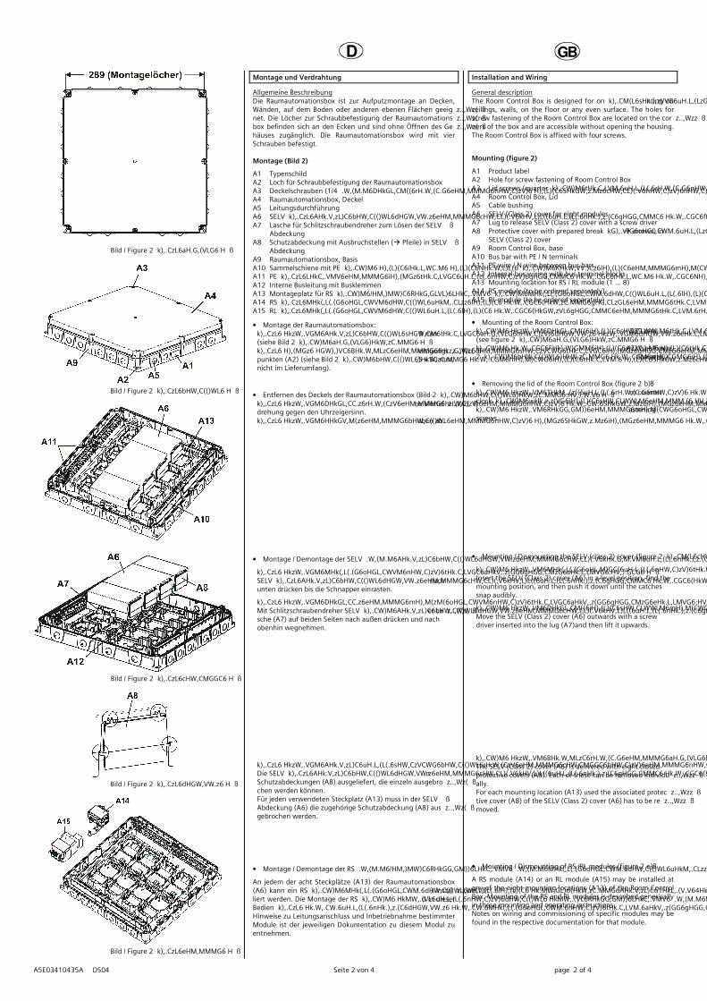
Allgemeine Beschreibung Die Raumautomationsbox ist zur Aufputzmontage an Decken, Wänden, auf dem Boden oder anderen ebenen Flächen geeignet. Die Löcher zur Schraubbefestigung der Raumautomationsbox befinden sich an den Ecken und sind ohne Öffnen des Gehäuses zugänglich. Die Raumautomationsbox wird mit vier Schrauben befestigt. Montage (Bild 2)
A1 Typenschild A2 Loch für Schraubbefestigung der Raumautomationsbox A3 Deckelschrauben (1/4 Dreh Schnellverschlüsse) A4 Raumautomationsbox, Deckel A5 Leitungsdurchführung A6 SELV Abdeckung für acht Modulplätze A7 Lasche für Schlitzschraubendreher zum Lösen der SELV
Abdeckung A8 Schutzabdeckung mit Ausbruchstellen ( Pfeile) in SELV
Abdeckung A9 Raumautomationsbox, Basis A10 Sammelschiene mit PE / N Klemmen A11 PE Leitung / N Leitung zwischen den Sammelschienen A12 Interne Busleitung mit Busklemmen A13 Montageplatz für RS /RL Modul (1 ... 8) A14 RS Modul (getrennt zu bestellen) A15 RL Modul (getrennt zu bestellen)
• Montage der Raumautomationsbox: Abstand der Bohrlöcher zur Schraubbefestigung: 289 mm (siehe Bild 2 a)
Befestigen Sie die Raumautomationsbox an den Befestigungspunkten (A2) (siehe Bild 2 b) mit Schrauben (z.B. 4,5 x 50 mm, nicht im Lieferumfang).
• Entfernen des Deckels der Raumautomationsbox (Bild 2 b): Drehen Sie die Schnellverschlussschrauben (A3) eine Vierteldrehung gegen den Uhrzeigersinn.
Heben Sie den Deckel (A4) mit den Verschlussschrauben ab. • Montage / Demontage der SELV Abdeckung (Bild 2 c):
Montage: SELV Abdeckung (A6) gerade aufsetzen, einfädeln und nach unten drücken bis die Schnapper einrasten.
Demontage: Mit Schlitzschraubendreher SELV Abdeckung (A6) an der Lasche (A7) auf beiden Seiten nach außen drücken und nach obenhin wegnehmen.
Ausbrechen der Schutzabdeckung (Bild 2 d): Die SELV Abdeckung (A6) wird mit acht verschlossenen Schutzabdeckungen (A8) ausgeliefert, die einzeln ausgebrochen werden können. Für jeden verwendeten Steckplatz (A13) muss in der SELVAbdeckung (A6) die zugehörige Schutzabdeckung (A8) ausgebrochen werden.
An jedem der acht Steckplätze (A13) der Raumautomationsbox (A6) kann ein RS Modul (A14) oder ein RL Modul (A15) installiert werden. Die Montage der RS und RL Module wird in dieser Bedien und Montageanleitung allgemein beschrieben. Hinweise zu Leitungsanschluss und Inbetriebnahme bestimmter Module ist der jeweiligen Dokumentation zu diesem Modul zu entnehmen.
Installation and Wiring
General description The Room Control Box is designed for on surface mounting on ceilings, walls, on the floor or any even surface. The holes for screw fastening of the Room Control Box are located on the corners of the box and are accessible without opening the housing. The Room Control Box is affixed with four screws.
Mounting (figure 2)
A1 Product label A2 Hole for screw fastening of Room Control Box
A3 Lid screws (quarter turn quick fastening screws) A4 Room Control Box, Lid A5 Cable bushing A6 SELV (Class 2) cover for eight modules A7 Lug to release SELV (Class 2) cover with a screw driver A8 Protective cover with prepared break outs ( arrows) in
SELV (Class 2) cover A9 Room Control Box, base A10 Bus bar with PE / N terminals A11 PE wire / N wire between bus bars A12 Internal bus wiring with bus terminal blocks A13 Mounting location for RS / RL module (1 ... 8) A14 RS module (to be ordered separately) A15 RL module (to be ordered separately)
• Mounting of the Room Control Box: Distance between drill holes for screw fastening: 289 mm (see figure 2 a)
Fix the Room Control Box at the fixation points (A2) (see figure 2 b) with screws (e.g. 4.5 x 50 mm, to be sourced separately).
• Removing the lid of the Room Control Box (figure 2 b): Turn the quick fastening screws (A3) a quarter turn counter clock wise.
Remove the lid (A4) with the quarter turn quick fastening screws.
• Mounting / Dismounting the SELV (class 2) cover (figure 2 c):
Mounting: Insert the SELV (Class 2) cover (A6) in a level position, find the mounting position, and then push it down until the catches snap audibly.
Dismounting: Move the SELV (Class 2) cover (A6) outwards with a screw driver inserted into the lug (A7)and then lift it upwards.
Breaking out the protective cover (figure 2 d): The SELV (Class 2) cover (A6) is delivered with eight closed protective covers (A8). Each of these can be removed individually. For each mounting location (A13) used the associated protective cover (A8) of the SELV (Class 2) cover (A6) has to be removed.
A RS module (A14) or an RL module (A15) may be installed at any of the eight mounting locations (A13) of the Room Control Box. Mounting of the RS and RL modules is described generically in these mounting and operating instructions. Notes on wiring and commissioning of specific modules may be found in the respective documentation for that module.
D
GB
A5E03410435A DS04 Seite 3 von 4 page 3 of 4
Bild / Figure 3 a
Bild / Figure 3 b
Bild / Figure 3 c
Bild / Figure 3 d
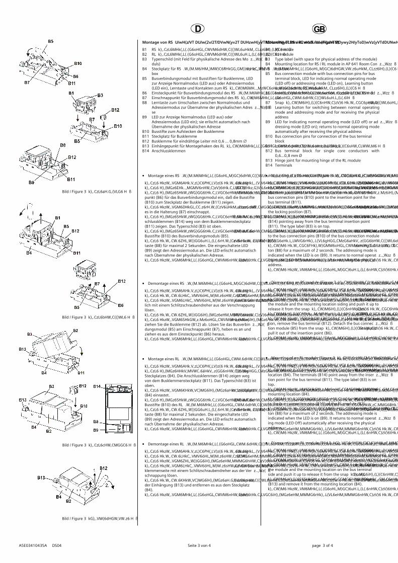
Montage von RS / RL Modulen (Bild 3)
B1 RS Modul B2 RL Modul B3 Typenschild (mit Feld für physikalische Adresse des Mo
duls) B4 Steckplatz für RS /RL Modul in AP 641 Raumautomations
box B5 Busverbindungsmodul mit Busstiften für Busklemme, LED
zur Anzeige Normalmodus (LED aus) oder Adressiermodus (LED ein), Lerntaste und Kontakten zum RS Modul
B6 Einsteckpunkt für Busverbindungsmodul des RS Moduls B7 Einschnappunkt für Busverbindungsmodul des RS Moduls B8 Lerntaste zum Umschalten zwischen Normalmodus und
Adressiermodus zur Übernahme der physikalischen Adresse
B9 LED zur Anzeige Normalmodus (LED aus) oder Adressiermodus (LED ein); sie erlischt automatisch nach Übernahme der physikalischen Adresse
B10 Busstifte zum Aufstecken der Busklemme B11 Steckplatz für Busklemme B12 Busklemme für eindrähtige Leiter mit 0,6 ... 0,8mm ∅ B13 Einhängepunkt für Montagehaken des RL Moduls B14 Anschlussklemmen
• Montage eines RS Moduls (Bild 3 a):
AP 641: Entfernen Sie den Deckel und die SELV Abdeckung Entfernen Sie die Busklemme (B12) vom Steckplatz (B11). Stecken Sie das Busverbindungsmodul (B5) so in den Einsteckpunkt (B6) für das Busverbindungsmodul ein, daß die Busstifte (B10) zum Steckplatz der Busklemme (B11) zeigen.
Drücken Sie das Busverbindungsmodul (B5) so nach unten, daß es in die Halterung (B7) einschnappt.
Stecken Sie das RS Modul (B1) von oben so ein, daß die Anschlussklemmen (B14) weg von dem Busklemmensteckplatz (B11) zeigen. Das Typenschild (B3) ist oben.
Stecken Sie die Busklemme (B12) des Steckplatzes (B4) auf die Busstifte (B10) des Busverbindungsmoduls (B5).
Zur Vergabe der physikalischen Adresse drücken Sie die Lerntaste (B8) für maximal 2 Sekunden. Die eingeschaltete LED (B9) zeigt den Adressiermodus an. Die LED erlischt automatisch nach Übernahme der physikalischen Adresse.
Montieren Sie den Deckel und die SELV Abdeckung wieder.
• Demontage eines RS Moduls (Bild 3 b):
AP 641: Entfernen Sie den Deckel und die SELV Abdeckung Lösen Sie die Leitungen aus den Anschlussklemmen (B14). Lösen Sie das RS Modul (B1), indem Sie das Modul jeweils seitlich mit einem Schlitzschraubendreher aus der Verschnappung lösen.
Ziehen Sie das RS Modul (B1) aus dem Steckplatz (B4) heraus. Soll ein RL Modul (B2) in den Steckplatz eingesetzt werden, ziehen Sie die Busklemme (B12) ab. Lösen Sie das Busverbindungsmodul (B5) am Einschnappunkt (B7), heben es an und ziehen es aus dem Einsteckpunkt (B6) heraus.
Montieren Sie den Deckel und die SELV Abdeckung wieder.
• Montage eines RL Moduls (Bild 3 c):
AP 641: Entfernen Sie den Deckel und die SELV Abdeckung Hängen Sie das RL Modul (B2) in die Einhängung (B13) des Steckplatzes (B4). Die Anschlussklemmen (B14) zeigen weg von dem Busklemmensteckplatz (B11). Das Typenschild (B3) ist oben.
Klappen Sie das RL Modul (B2) nach unten bis es im Steckplatz (B4) einrastet.
Stecken Sie die Busklemme (B12) des Steckplatzes (B4) auf die Busstifte (B10) des RL Moduls (B2).
Zur Vergabe der physikalischen Adresse drücken Sie die Lerntaste (B8) für maximal 2 Sekunden. Die eingeschaltete LED (B9) zeigt den Adressiermodus an. Die LED erlischt automatisch nach Übernahme der physikalischen Adresse.
Montieren Sie den Deckel und die SELV Abdeckung wieder.
• Demontage eines RL Moduls (Bild 3 d):
AP 641: Entfernen Sie den Deckel und die SELV Abdeckung Lösen Sie die Leitungen aus den Anschlussklemmen (B14). Ziehen Sie die Busklemme (B12) ab. Lösen Sie das RL Modul (B2), indem Sie das Modul auf der Busklemmenseite mit einem Schlitzschraubendreher aus der Verschnappung lösen.
Klappen Sie das RL Modul (B2) hoch, ziehen es nach unten aus der Einhängung (B13) und entfernen es aus dem Steckplatz (B4).
Montieren Sie den Deckel und die SELV Abdeckung wieder.
Mounting of RS / RL modules (Figure 3)
B1 RS module B2 RL module B3 Type label (with space for physical address of the module) B4 Mounting location for RS / RL module in AP 641 Room Con
trol Box B5 Bus connection module with bus connection pins for bus
terminal block, LED for indicating normal operating mode (LED off) or addressing mode (LED on), Learning button and contacts to RS module
B6 Insertion point for bus connection module of the RS module
B7 Snap in point for bus connection module of the RS module B8 Learning button for switching between normal operating
mode and addressing mode and for receiving the physical address
B9 LED for indicating normal operating mode (LED off) or addressing mode (LED on); returns to normal operating mode automatically after receiving the physical address
B10 Bus connection pins for connection of the bus terminal block
B11 Insertion point for bus terminal block B12 Bus terminal block for single core conductors with
0,6...0,8 mm Ø B13 Hinge joint for mounting hinge of the RL module B14 Terminals
• Mounting of a RS module (Figure 3 a):
AP 641: Remove the box cover and the SELV (Class 2) cover Insert the bus connection module (B5) in such a way into the insertion point (B6) for the bus connection module that the bus connection pins (B10) point to the insertion point for the bus terminal (B11).
Press the bus connection module (B5) down until it snaps into the locking position (B7).
Insert the RS module (B1) from the top with the terminals (B14) pointing away from the bus terminal insertion point (B11). The type label (B3) is on top.
Insert the bus terminal (B12) of the mounting location (B4) onto the bus connection pins (B10) of the bus connection module (B5).
For assignment of the Physical Address press the learning button (B8) for a maximum of 2 seconds. The addressing mode is indicated when the LED is on (B9). It returns to normal operating mode (LED Off) automatically after receiving the physical address.
Mount the lid and the SELV (Class 2) cover again.
• Dismounting an RS module (Figure 3 b):
AP 641: Remove the box cover and the SELV (Class 2) cover Remove the wiring from the terminals (B14). To remove the RS module (B1), insert a screw driver between the module and the mounting location siding and push it up to release it from the snap in hooks. Do this on both sides.
Pull the RS module (B1) from the mounting location (B4). If an RL module (B2) shall be inserted into the mounting location, remove the bus terminal (B12). Detach the bus connection module (B5) from the snap in point (B7), swivel it up and pull it out of the insertion point (B6).
Mount the lid and the SELV (Class 2) cover again. • Mounting of an RL module (Figure 3 c):
AP 641: Remove the box cover and the SELV (Class 2) cover Insert the RL module (B2) into the hinge (B13) of the mounting location (B4). The terminals (B14) point away from the insertion point for the bus terminal (B11). The type label (B3) is on top.
Swivel the RL module (B2) down until it audibly snaps into the mounting location (B4).
Insert the bus terminal (B12) of the mounting location (B4) onto the bus connection pins (B10) of the RL module (B2).
For assignment of the Physical Address press the learning button (B8) for a maximum of 2 seconds. The addressing mode is indicated when the LED is on (B9). It returns to normal operating mode (LED Off) automatically after receiving the physical address.
Mount the lid and the SELV (Class 2) cover again.
• Dismounting an RL module (Bild 3 d):
AP 641: Remove the box cover and the SELV (Class 2) cover Remove the wiring from the terminals (B14). Remove the bus terminal (B12). To remove the RL module (B2), insert a screw driver between the module and the mounting location on the bus terminal side and push it up to release it from the snap in hooks.
Swivel the RL module (B2) up, pull it down out of the hinge (B13) and remove it from the mounting location (B4).
Mount the lid and the SELV (Class 2) cover again.
D
GB
A5E03410435A DS04 Seite 4 von 4 page 4 of 4
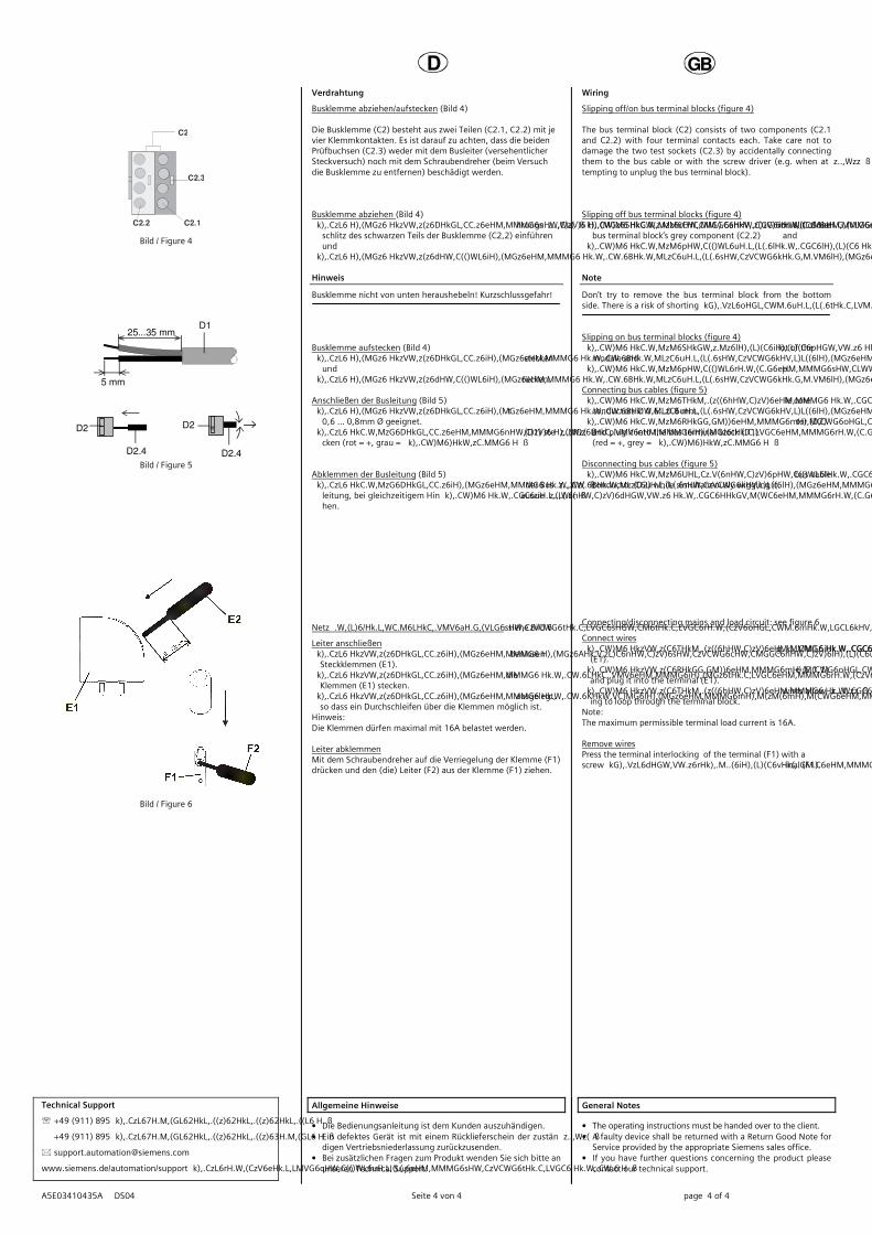
C2
C2.2 C2.1
C2.3
Bild / Figure 4
D2
D2.4
5 mm
D2
D2.4
25...35 mmD1
Bild / Figure 5
Bild / Figure 6
Verdrahtung
Busklemme abziehen/aufstecken (Bild 4) Die Busklemme (C2) besteht aus zwei Teilen (C2.1, C2.2) mit je vier Klemmkontakten. Es ist darauf zu achten, dass die beiden Prüfbuchsen (C2.3) weder mit dem Busleiter (versehentlicher Steckversuch) noch mit dem Schraubendreher (beim Versuch die Busklemme zu entfernen) beschädigt werden. Busklemme abziehen (Bild 4) Den Schraubendreher vorsichtig in den Drahteinführungs
schlitz des schwarzen Teils der Busklemme (C2,2) einführen und
die Busklemme (C2) aus dem Modul herausziehen. Hinweis
Busklemme nicht von unten heraushebeln! Kurzschlussgefahr! Busklemme aufstecken (Bild 4) Die Busklemme (C2) in die Führungsnut des Moduls stecken
und die Busklemme (C2) bis zum Anschlag nach unten drücken.
Anschließen der Busleitung (Bild 5) Die Busklemme (D1) ist für eindrähtige Leiter mit
0,6 ... 0,8mm Ø geeignet. Den Leiter (D2) ca. 5mm abisolieren und in Klemme (D1) ste
cken (rot = +, grau = ) Abklemmen der Busleitung (Bild 5) Die Busklemme (D2) abziehen und den Leiter (D2.4) der Bus
leitung, bei gleichzeitigem Hin und Herdrehen, herausziehen.
Netz /Laststromkreis anschließen und abklemmen: siehe Bild 6
Leiter anschließen Die Anschlüsse für die Leiter bestehen aus schraubenlosen
Steckklemmen (E1). Die Leiter (E2) ca. 9 ... 10mm abisolieren und in die
Klemmen (E1) stecken. Die Klemmen sind für das Einstecken zweier Leiter ausgelegt,
so dass ein Durchschleifen über die Klemmen möglich ist. Hinweis: Die Klemmen dürfen maximal mit 16A belastet werden. Leiter abklemmen Mit dem Schraubendreher auf die Verriegelung der Klemme (F1) drücken und den (die) Leiter (F2) aus der Klemme (F1) ziehen.
Wiring
Slipping off/on bus terminal blocks (figure 4) The bus terminal block (C2) consists of two components (C2.1 and C2.2) with four terminal contacts each. Take care not to damage the two test sockets (C2.3) by accidentally connecting them to the bus cable or with the screw driver (e.g. when attempting to unplug the bus terminal block). Slipping off bus terminal blocks (figure 4) Carefully put the screw driver to the wire insertion slit of the
bus terminal block’s grey component (C2.2) and pull the bus terminal block (C2) from the module.
Note
Don’t try to remove the bus terminal block from the bottom side. There is a risk of shorting out the device! Slipping on bus terminal blocks (figure 4) Slip the bus terminal block (C2) onto the guide slot of the
module and press the bus terminal block (C2) down to the stop.
Connecting bus cables (figure 5) The bus terminal block (D1) can be used with single core
conductors Ø 0.6…0.8 mm. Remove approx. 5 mm of insulation from the conductor (D2)
and plug it into the bus terminal block (D1) (red = +, grey = )
Disconnecting bus cables (figure 5) Unplug the bus terminal block (D1) and remove the bus cable
conductor (D2) while simultaneously wiggling it. Connecting/disconnecting mains and load circuit: see figure 6
Connect wires The load circuits are connected via screwless plug in terminals
(E1). Remove approx. 9…10 mm of insulation from the wire (E 1.1)
and plug it into the terminal (E1). The terminals are designed for connection of two wires allow
ing to loop through the terminal block. Note: The maximum permissible terminal load current is 16A. Remove wires Press the terminal interlocking of the terminal (F1) with a screw driver and remove the wire (F2) from the terminal (F1).