52
DILLIMAX TECHNICAL INFORMATION NO. III/2007 MAKE SAVINGS WITH HIGH STRENGTH STEEL DILLINGER HÜTTE GTS
| Date post: | 29-Oct-2015 |
| Category: |
Documents |
| Upload: | sohanlal29 |
| View: | 55 times |
| Download: | 0 times |

DILLIMAXTECHNICAL INFORMATION NO. III /2007
MAKE SAVINGS WITH HIGH STRENGTH STEEL
DILLINGER HÜTTE GTS
eng_01-52_0849_dihd_max.411 04.04.2007 8:37 Uhr Seite 1

eng_01-52_0849_dihd_max.411 04.04.2007 8:37 Uhr Seite 2
eng_01-52_0849_dihd_max.411 04.04.2007 8:37 Uhr Seite 1

April 2007
eng_01-52_0849_dihd_max.411 04.04.2007 8:37 Uhr Seite 2
4Weight-Watching for your Steel Structures
6The Manufacture of DILLIMAX
Melting the SteelShaping into Heavy Plate
Water Quenching
8The Material Properties of DILLIMAX
Strength and ToughnessProperties in Through-Thickness Direction
High-Temperature Strength
12The Processing of DILLIMAX
Cold FormingHot Forming
Forming within the Stress Relieving Temperature Range
Thermal CuttingWelding
Stress RelievingFlame Straightening
GalvanizingMachining
38The Component Properties of DILLIMAX
44Literature
46Index
CONTENTS
eng_01-52_0849_dihd_max.411 04.04.2007 8:37 Uhr Seite 3
4
The bearing capacity of steelstructures such as crane booms,heavy utility vehicles chassisconstruction, steel constructions,flood gates or bridges is consid-erable. To demand that suchstructures also comply with theprinciple of light-gauge design –reduced use of material, goodand easy machinability – would have been very difficult to achieve only a few years ago. Today, however, both of these requirements can be combinedwithout any problems.
We would like to introduce toyou a group of steels with whichyou can build structures with ahigh-load capacity and maxi-mum of safety, and at the sametime reduce material and fabri-cation costs by up to 50 %: DILLIMAX steels fromDILLINGER HÜTTE GTS.
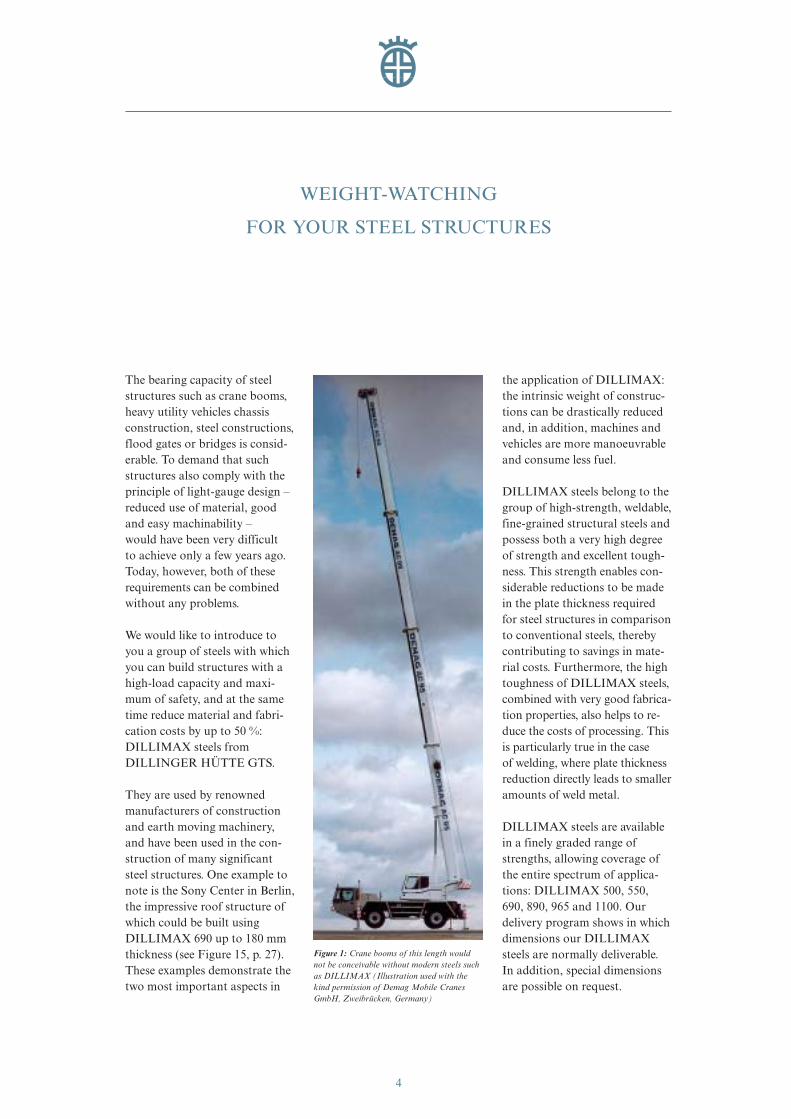
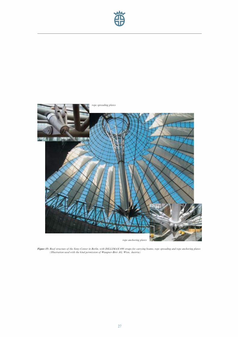
They are used by renownedmanufacturers of constructionand earth moving machinery,and have been used in the con-struction of many significantsteel structures. One example tonote is the Sony Center in Berlin,the impressive roof structure ofwhich could be built usingDILLIMAX 690 up to 180 mmthickness (see Figure 15, p. 27).These examples demonstrate thetwo most important aspects in
the application of DILLIMAX:the intrinsic weight of construc-tions can be drastically reducedand, in addition, machines and vehicles are more manoeuvrableand consume less fuel.
DILLIMAX steels belong to thegroup of high-strength, weldable,fine-grained structural steels andpossess both a very high degreeof strength and excellent tough-ness. This strength enables con-siderable reductions to be madein the plate thickness requiredfor steel structures in comparisonto conventional steels, therebycontributing to savings in mate-rial costs. Furthermore, the hightoughness of DILLIMAX steels,combined with very good fabrica-tion properties, also helps to re-duce the costs of processing. Thisis particularly true in the case of welding, where plate thicknessreduction directly leads to smalleramounts of weld metal.
DILLIMAX steels are availablein a finely graded range ofstrengths, allowing coverage ofthe entire spectrum of applica-tions: DILLIMAX 500, 550,690, 890, 965 and 1100. Our delivery program shows in whichdimensions our DILLIMAXsteels are normally deliverable.In addition, special dimensionsare possible on request.
WEIGHT-WATCHING
FOR YOUR STEEL STRUCTURES
Figure 1: Crane booms of this length wouldnot be conceivable without modern steels suchas DILLIMAX (Illustration used with thekind permission of Demag Mobile CranesGmbH, Zweibrücken, Germany)
eng_01-52_0849_dihd_max.411 04.04.2007 8:37 Uhr Seite 4
5
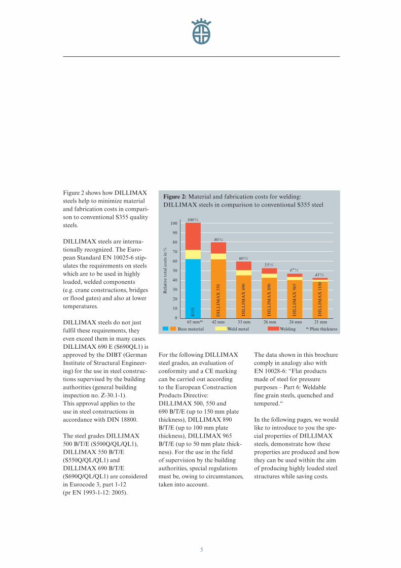
Figure 2 shows how DILLIMAXsteels help to minimize materialand fabrication costs in compari-son to conventional S355 qualitysteels.
DILLIMAX steels are interna-tionally recognized. The Euro-pean Standard EN 10025-6 stip-ulates the requirements on steelswhich are to be used in highlyloaded, welded components (e.g. crane constructions, bridgesor flood gates) and also at lowertemperatures.
DILLIMAX steels do not just fulfil these requirements, theyeven exceed them in many cases.DILLIMAX 690 E (S690QL1) isapproved by the DIBT (GermanInstitute of Structural Engineer-ing) for the use in steel construc-tions supervised by the buildingauthorities (general building inspection no. Z-30.1-1). This approval applies to the use in steel constructions in accordance with DIN 18800.
The steel grades DILLIMAX500 B/T/E (S500Q/QL/QL1),DILLIMAX 550 B/T/E(S550Q/QL/QL1) and DILLIMAX 690 B/T/E(S690Q/QL/QL1) are consideredin Eurocode 3, part 1-12 (pr EN 1993-1-12: 2005).
For the following DILLIMAXsteel grades, an evaluation ofconformity and a CE markingcan be carried out according to the European ConstructionProducts Directive: DILLIMAX 500, 550 and 690 B/T/E (up to 150 mm platethickness), DILLIMAX 890B/T/E (up to 100 mm platethickness), DILLIMAX 965B/T/E (up to 50 mm plate thick-ness). For the use in the field of supervision by the buildingauthorities, special regulationsmust be, owing to circumstances,taken into account.
The data shown in this brochurecomply in analogy also with EN 10028-6: “Flat productsmade of steel for pressure purposes – Part 6: Weldable fine grain steels, quenched andtempered.“
In the following pages, we wouldlike to introduce to you the spe-cial properties of DILLIMAXsteels, demonstrate how theseproperties are produced and howthey can be used within the aimof producing highly loaded steelstructures while saving costs.
Figure 2: Material and fabrication costs for welding: DILLIMAX steels in comparison to conventional S355 steel
100
90
80
70
60
50
40
30
20
10
065 mm*) 42 mm 33 mm 26 mm 24 mm 21 mm
DIL
LIM
AX
550
DIL
LIM
AX
690
DIL
LIM
AX
890
DIL
LIM
AX
1100
Rel
ativ
e to
tal c
osts
in %
Base material Weld metal Welding *) Plate thickness
100 %
80 %
60 %
53 %
43 %
DIL
LIM
AX
965
47 %
S355
eng_01-52_0849_dihd_max.411 04.04.2007 8:37 Uhr Seite 5
6
The high degree of strength andtoughness displayed by DILLI-MAX steels is not only achievedby selective alloying, but also bya special manufacturing process:after rolling, the heavy plates arequenched in water and tempered.All processes involved – steelproduction, shaping into heavyplate and water quenching – areexactly combined for each steelmelt.
Melting the Steel
After careful hot metal desul-phurization, DILLIMAX steelsare produced by melting in atop-blowing basic oxygen process,then treated by ladle metallurgy
and, for usual plate dimensions,cast by continuous casting. Forvery thick, heavy plates, ingotcasting is also available.
A low phosphorus and sulphurcontent are both prerequisitesfor high toughness. As a rule,the phosphorus content is below0.020 % and the sulphur contentbelow 0.005 %. The requiredalloy content is exactly adjustedin the ladle as well, with a viewto an optimum combination ofmechanical values and goodmachinability.
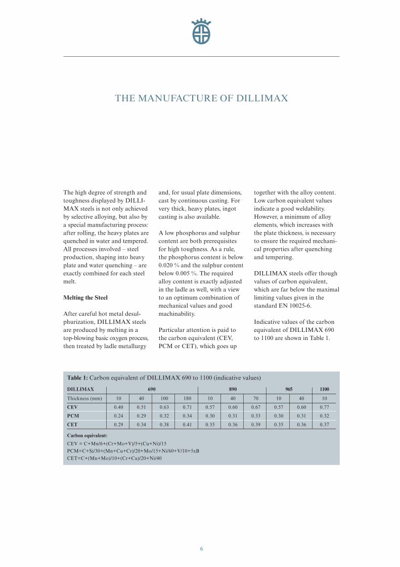
Particular attention is paid tothe carbon equivalent (CEV,PCM or CET), which goes up
together with the alloy content.Low carbon equivalent valuesindicate a good weldability.However, a minimum of alloyelements, which increases withthe plate thickness, is necessaryto ensure the required mechani-cal properties after quenchingand tempering.
DILLIMAX steels offer thoughvalues of carbon equivalent,which are far below the maximallimiting values given in the standard EN 10025-6.
Indicative values of the carbonequivalent of DILLIMAX 690to 1100 are shown in Table 1.
THE MANUFACTURE OF DILLIMAX
Table 1: Carbon equivalent of DILLIMAX 690 to 1100 (indicative values)
DILLIMAX 690 890 965 1100
Thickness (mm) 10 40 100 180 10 40 70 10 40 10
CEV 0.40 0.51 0.63 0.71 0.57 0.60 0.67 0.57 0.60 0.77
PCM 0.24 0.29 0.32 0.34 0.30 0.31 0.33 0.30 0.31 0.32
CET 0.29 0.34 0.38 0.41 0.35 0.36 0.39 0.35 0.36 0.37
Carbon equivalent:
CEV = C+Mn/6+(Cr+Mo+V)/5+(Cu+Ni)/15PCM=C+Si/30+(Mn+Cu+Cr)/20+Mo/15+Ni/60+V/10+5xBCET=C+(Mn+Mo)/10+(Cr+Cu)/20+Ni/40
eng_01-52_0849_dihd_max.411 04.04.2007 8:37 Uhr Seite 6
7
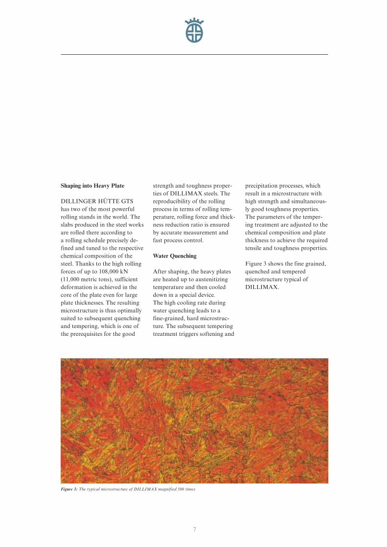
Figure 3: The typical microstructure of DILLIMAX magnified 500 times
Shaping into Heavy Plate
DILLINGER HÜTTE GTS has two of the most powerfulrolling stands in the world. Theslabs produced in the steel worksare rolled there according to a rolling schedule precisely de-fined and tuned to the respectivechemical composition of thesteel. Thanks to the high rollingforces of up to 108,000 kN(11,000 metric tons), sufficientdeformation is achieved in thecore of the plate even for largeplate thicknesses. The resultingmicrostructure is thus optimallysuited to subsequent quenchingand tempering, which is one ofthe prerequisites for the good
strength and toughness proper-ties of DILLIMAX steels. Thereproducibility of the rollingprocess in terms of rolling tem-perature, rolling force and thick-ness reduction ratio is ensuredby accurate measurement andfast process control.
Water Quenching
After shaping, the heavy platesare heated up to austenitizingtemperature and then cooleddown in a special device. The high cooling rate duringwater quenching leads to a fine-grained, hard microstruc-ture. The subsequent temperingtreatment triggers softening and
precipitation processes, whichresult in a microstructure withhigh strength and simultaneous-ly good toughness properties.The parameters of the temper-ing treatment are adjusted to thechemical composition and platethickness to achieve the requiredtensile and toughness properties.
Figure 3 shows the fine grained,quenched and temperedmicrostructure typical ofDILLIMAX.
eng_01-52_0849_dihd_max.411 04.04.2007 8:37 Uhr Seite 7
THE MATERIAL PROPERTIES OF DILLIMAX
8
Strength and Toughness
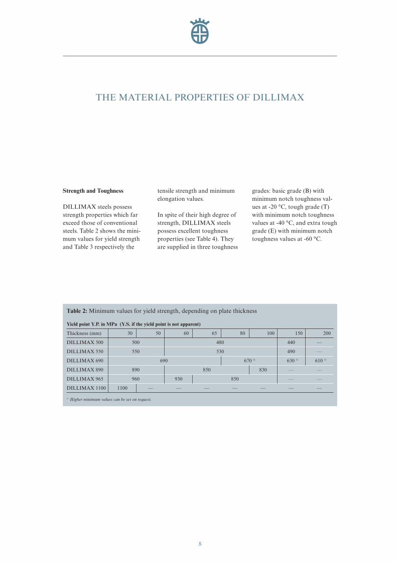
DILLIMAX steels possessstrength properties which farexceed those of conventionalsteels. Table 2 shows the mini-mum values for yield strengthand Table 3 respectively the
tensile strength and minimumelongation values.
In spite of their high degree ofstrength, DILLIMAX steelspossess excellent toughnessproperties (see Table 4). Theyare supplied in three toughness
grades: basic grade (B) withminimum notch toughness val-ues at -20 °C, tough grade (T)with minimum notch toughnessvalues at -40 °C, and extra toughgrade (E) with minimum notchtoughness values at -60 °C.
Table 2: Minimum values for yield strength, depending on plate thickness
Yield point Y.P. in MPa (Y.S. if the yield point is not apparent)
Thickness (mm) 30 50 60 65 80 100 150 200
DILLIMAX 500 500 480 440 —
DILLIMAX 550 550 530 490 —
DILLIMAX 690 690 670 1) 630 1) 610 1)
DILLIMAX 890 890 850 830 — —
DILLIMAX 965 960 930 850 — —
DILLIMAX 1100 1100 — — — — — — —
1) Higher minimum values can be set on request.
eng_01-52_0849_dihd_max.411 04.04.2007 8:37 Uhr Seite 8
9
Table 4: Minimum values for impact energy of DILLIMAX steels (Charpy-V-notch samples)
DILLIMAX 500–965 Specimen direction Impact energy Av [J] at a test temperature of
0 °C - 20 °C - 40 °C - 60 °C
Basic grade (B) longitudinal/transverse 40/30 30/27 — —
Tough grade (T) longitudinal/transverse 50/35 40/30 30/27 —
Extra tough grade (E) longitudinal/transverse 60/40 50/35 40/30 30/27
For DILLIMAX 1100, minimum impact energy values of respectively 30 J in longitudinal direction and 27 J in transversedirection at -40 °C are offered.
Table 3: Minimum values for tensile strength and elongation, depending on plate thickness
ElongationTensile Strength U.T.S. in MPa A5 in % 2)
Thickness (mm) 30 50 60 80 100 150 200 all thickness'
DILLIMAX 500 590 – 770 540 – 720 — 17
DILLIMAX 550 640 – 820 590 – 770 — 16
DILLIMAX 690 770 – 940 720 – 900 1) 700 – 880 1) 14
DILLIMAX 890 940 – 1100 900 – 1100 880 – 1100 — — 12
DILLIMAX 965 980 – 1150 950 – 1120 900 – 1100 — — 12
DILLIMAX 1100 1200 – 1500 — — — — — — 10
1) Higher minimum values can be set on request.2) Minimum elongation.
eng_01-52_0849_dihd_max.411 04.04.2007 8:37 Uhr Seite 9
10
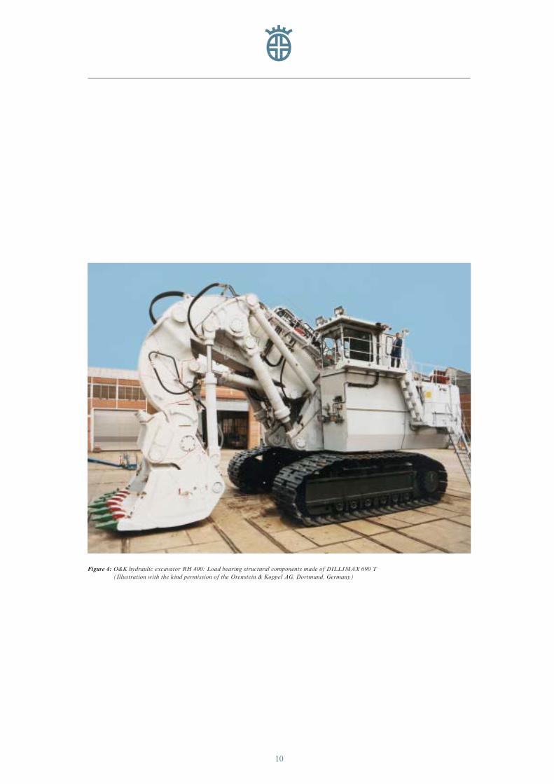
Figure 4: O&K hydraulic excavator RH 400: Load bearing structural components made of DILLIMAX 690 T(Illustration with the kind permission of the Orenstein & Koppel AG, Dortmund, Germany)
eng_01-52_0849_dihd_max.411 04.04.2007 8:37 Uhr Seite 10
11
Properties in Through-ThicknessDirection
Plates, which are used under ahigh load in through-thickness direction because of construc-tive and/or manufacturing rea-sons, require a high resistanceagainst lamellar tearing.
This must be taken into accountfor the steel production throughthe settings of a special produc-tion route.
Thus, for example, DILLIMAX 690 can be de-livered by agreement in a largethickness range under fulfilmentof the quality class Z35 in accordance with EN 10164.
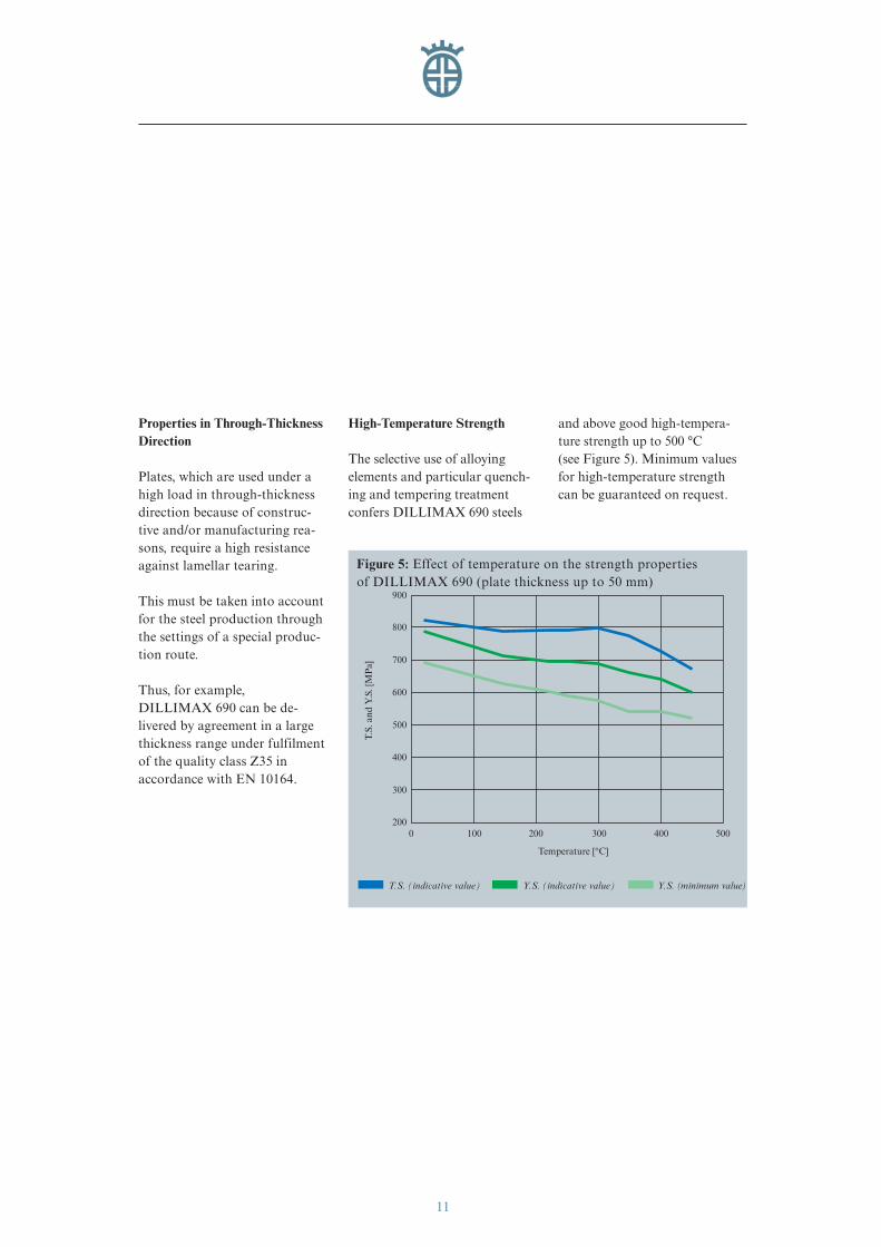
High-Temperature Strength
The selective use of alloying elements and particular quench-ing and tempering treatmentconfers DILLIMAX 690 steels
and above good high-tempera-ture strength up to 500 °C(see Figure 5). Minimum valuesfor high-temperature strengthcan be guaranteed on request.
900
800
700
500
400
300
2000 100
Temperature [°C]
500400200 300
T.S.
and
Y.S
. [M
Pa]
600
Figure 5: Effect of temperature on the strength properties of DILLIMAX 690 (plate thickness up to 50 mm)
T.S. (indicative value) Y.S. (indicative value) Y.S. (minimum value)
eng_01-52_0849_dihd_max.411 04.04.2007 8:37 Uhr Seite 11
THE PROCESSING OF DILLIMAX
12
It must generally be taken intoaccount, that the processing requires more care as the mini-mum yield strength values ofthe steels and/or the plate thick-ness increase, in order to ruleout an inadmissible deteriora-tion of the mechanical proper-ties. It also must be considered,that the chemical compositionof DILLIMAX steels varies de-pending on the plate thickness,from which certain differencesin the processing may result.
A construction suitable to theapplication is a fundamentalcondition for a successful use of high strength, fine-grainedstructural steels. On the basis of relevant standards, the usershould ensure that his design,construction and processingmethods are aligned with thematerial, correspond to thestate-of-the-art that the fabri-cator has to comply with and are suitable for the intended application.
In this brochure some funda-mental advice for the processing
of DILLIMAX steels is given.Of course, not all the possibili-ties and boundary conditions of the processing can be com-mented. Please contactDILLINGER HÜTTE GTS for your special questions.
Cold forming
Cold forming of DILLIMAXsteels can easily be carried out bybending. It must be noted thatthe force needed to form a givenplate thickness increases with the yield strength of the steel.The elastic spring back effect also becomes more significant.
In order to prevent the dangerof cracks arising from thesheared or flame cut edges,these must be ground in the areas where cold forming is in-tended. Shearing burs shall be removed and edges rounded.Deep drag lines and gougingsshall be ground flush in order to prevent stress and strain con-centrations during cold forming.For high strength steels, notches
(e.g. hard stemps) on the platesurface increase the risk of acrack formation and shall be removed in the forming area.
The elongation of steel decreas-es as its yield strength increases.This law must be taken into ac-count for cold forming as wellby adapting the maximum plas-tic elongation applied to theyield strength class. The plasticelongation on the plate surface,which occurs during bending,arises from the bending radius (r) and the plate thick-ness (t), following the rule:Elongation (%) = 100 / (1+2 r / t).
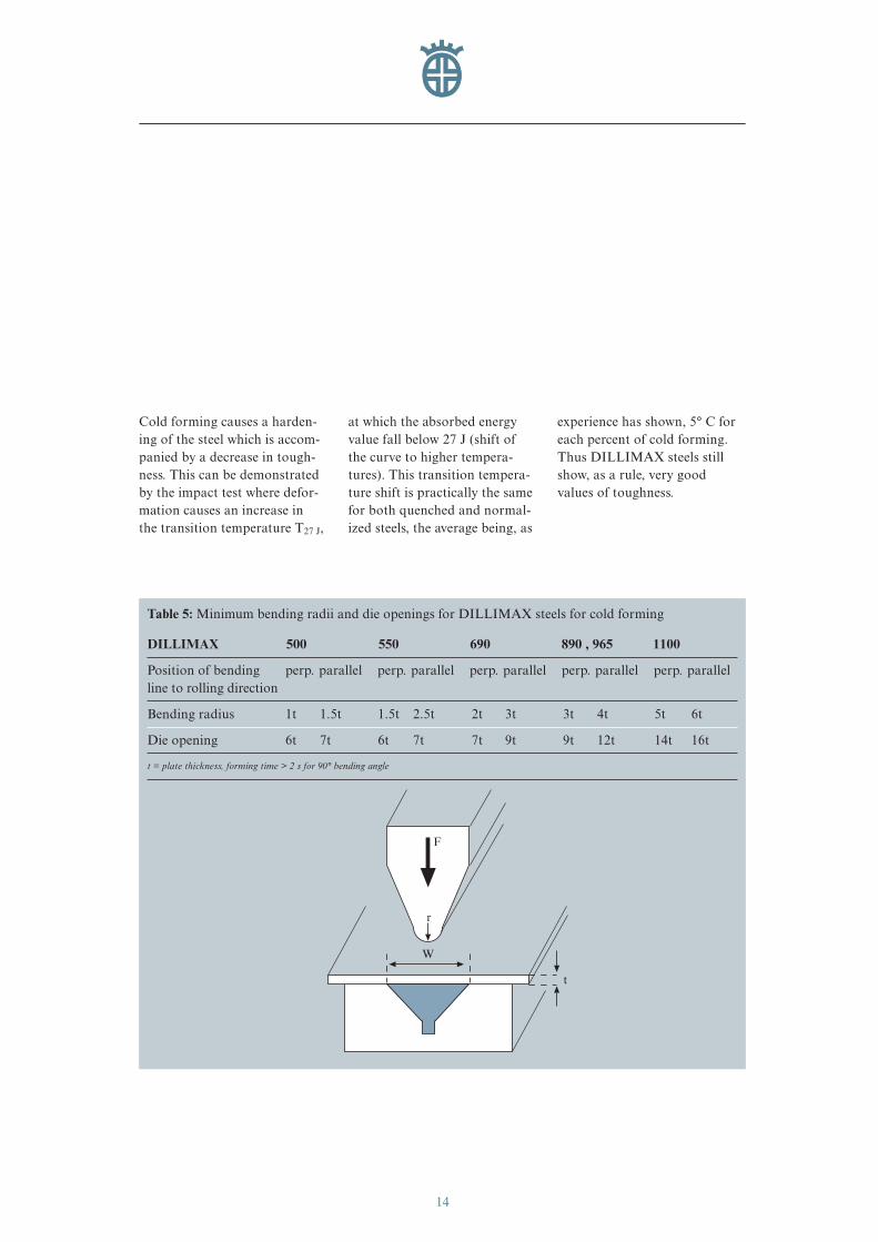
Assuming a certain maximumdeformation rate (less than 10 %elongation per second in theouter fibre), certain minimumbending radii and die openingscan be used as reference valuesfor DILLIMAX (see Table 5).
eng_01-52_0849_dihd_max.411 04.04.2007 8:37 Uhr Seite 12
13
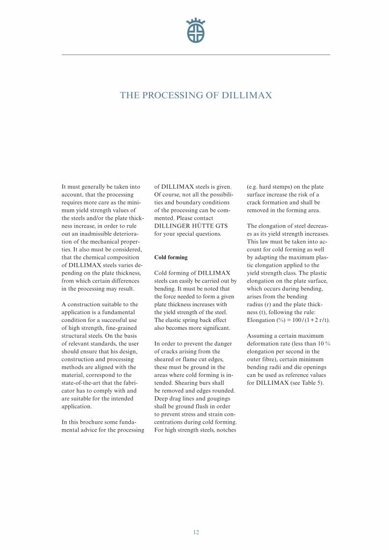
Figure 6: Pipes made of DILLIMAX 690 for the penstock linings of the hydropower plant Kárahnjúkar(Illustration used with the kind permission of DSD Noell GmbH, Würzburg, Germany)
eng_01-52_0849_dihd_max.411 04.04.2007 8:37 Uhr Seite 13
14
Cold forming causes a harden-ing of the steel which is accom-panied by a decrease in tough-ness. This can be demonstratedby the impact test where defor-mation causes an increase in the transition temperature T27 J,
at which the absorbed energyvalue fall below 27 J (shift of the curve to higher tempera-tures). This transition tempera-ture shift is practically the samefor both quenched and normal-ized steels, the average being, as
experience has shown, 5° C foreach percent of cold forming.Thus DILLIMAX steels stillshow, as a rule, very good values of toughness.
Table 5: Minimum bending radii and die openings for DILLIMAX steels for cold forming
DILLIMAX 500 550 690 890 , 965 1100
Position of bending perp. parallel perp. parallel perp. parallel perp. parallel perp. parallelline to rolling direction
Bending radius 1t 1.5t 1.5t 2.5t 2t 3t 3t 4t 5t 6t
Die opening 6t 7t 6t 7t 7t 9t 9t 12t 14t 16t
t = plate thickness, forming time > 2 s for 90° bending angle
W
t
r
F
eng_01-52_0849_dihd_max.411 04.04.2007 8:37 Uhr Seite 14
15
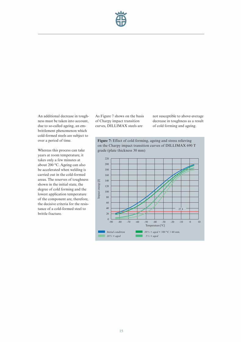
An additional decrease in tough-ness must be taken into account,due to so-called ageing, an em-brittlement phenomenon whichcold-formed steels are subject toover a period of time.
Whereas this process can takeyears at room temperature, ittakes only a few minutes atabout 200 °C. Ageing can alsobe accelerated when welding iscarried out in the cold-formedareas. The reserves of toughnessshown in the initial state, thedegree of cold forming and thelowest application temperatureof the component are, therefore,the decisive criteria for the resis-tance of a cold-formed steel tobrittle fracture.
As Figure 7 shows on the basisof Charpy impact transitioncurves, DILLIMAX steels are
not susceptible to above-averagedecrease in toughness as a resultof cold forming and ageing.
0
20
40
60
80
100
120
140
160
180
200
220
-90 -80 -70 -60 -50 -40 -30 -20 -10 0 10 Temperature [°C]
Impa
ct e
nerg
y [J
]
Figure 7: Effect of cold forming, ageing and stress relieving on the Charpy impact transition curves of DILLIMAX 690 Tgrade (plate thickness 30 mm)
Initial condition 10 % + aged + 580 °C / 60 min.
10 % + aged 5 % + aged
27 J
eng_01-52_0849_dihd_max.411 04.04.2007 8:37 Uhr Seite 15
16
Annealing in the stress relievingtemperature range (see section“Stress relieving”, p. 33) carriedout after forming reduces age-ing-induced embrittlement.
Depending on the applicationfor which the DILLIMAX steelsare intended, various fabricationcodes apply, which lay down the maximum permissible scope of cold forming and stipulatethe corresponding heat treat-ment. Also welding in strongcold formed areas (e. g. > 5 %) is forbidden in some fabricationcodes. If the welded componentis to be stress relieved, separateannealing after cold forming can be dispensed with.
Hot Forming
In the case of narrow bendingradii and large wall thicknesses,it may be advantageous to carryout forming at higher tempera-tures, since the required formingforces are lower. This method,however, has a serious disadvan-tage: hot forming takes place, asa rule, above the maximum per-missible temperature for stress
relieving. In this temperaturerange, DILLIMAX steels in-evitably lose their originalmechanical properties resultingfrom the water quenching.
Consequently, hot formingDILLIMAX steels is not per-missible if no renewed quenchingand tempering is subsequentlyto be carried out.
Even with renewed quenchingand tempering, it should be not-ed that the mechanical proper-ties of DILLIMAX steels maydeteriorate. DILLINGERHÜTTE GTS cannot guaranteesatisfactory results with renewedquenching and tempering.Firstly, the efficiency of the heat treatment equipment whichmanufacturers have at their dis-posal varies a great deal, andsecondly, satisfactory quenchingand tempering results are moredifficult to achieve due to thecomponent geometry which, in comparison to unprocessedplate, is more complicated. Con-sequently, the chemical compo-sition of the steel must be ad-justed accordingly beforehand in
consultation with DILLINGERHÜTTE GTS for componentswhich are to be quenched andtempered during fabrication.
As far as is possible, austenitiz-ing of DILLIMAX steels shouldtake place at temperatures be-tween 900 °C and 950 °C if re-newed quenching and temperingis intended. During subsequenthardening in water, a high rateof heat dissipation should be ensured in order to secure suffi-cient hardening of the compo-nent. The subsequent temperingprocess depends on the chemicalcomposition, dimensions and required mechanical propertiesand should likewise be deter-mined in consultation withDILLINGER HÜTTE GTS.
eng_01-52_0849_dihd_max.411 04.04.2007 8:37 Uhr Seite 16
17
Forming within the StressRelieving Temperature Range
According to definition, thisprocess belongs to the cold form-ing category. However, in thisrange of temperature, the yieldstrength is already significantlylower than at room temperature,and the forming forces requiredthus decrease proportionally,without any decisive change,however, in the initial heat treat-ment microstructure. In addi-tion, toughness is less impairedthan when cold forming at roomtemperature.
Subsequent renewed quenchingand tempering can be dispensedwith if forming temperatures areapproximately 50 °C to 80 °Cbelow the tempering temperatureand the amount of working isunder 2 %.
When higher amounts of work-ing are involved, it should be de-termined whether the mechani-cal values of the steel (toughness,elongation) are still reached afterforming.
The forming of DILLIMAX 1100within the stress relieving temper-ature range is not permissible.
Thermal Cutting
Flame cutting, plasma arc cut-ting or laser cutting of DILLI-MAX steels is possible withoutdifficulty, if carried out properlyand using appropriate tools ingood working condition.
Since different manufacturershave developed a variety of tools,you should note the respectivesettings and advice prescribed bythe manufacturers in the cuttingtables (nozzle selection, gas pres-sure, working methods, speedetc.).
The surface condition of theplate also has a pronounced in-fluence on the flame cutting con-ditions and the cut face qualitythat can be achieved. Where highdemands are placed on the cutface quality, it is necessary toclean the top and bottom of theworkpiece around the cut fromscale, rust, paint and any otherimpurities.
Generally, it is not necessary to preheat Dillimax 500 prior to flame and arc cutting if thetemperature of the workpiece is15 °C or above. However, for the high strength DILLIMAXsteels, if the cutting edges are to undergo cold forming in thecourse of further processing, e.g.through bending, a zone appro-ximately 100 mm wide within theforming area has to be preheatedto a temperature between 120 °Cand 200 °C. Alternatively, thehardened areas resulting fromflame cutting must be groundaway in the forming area.
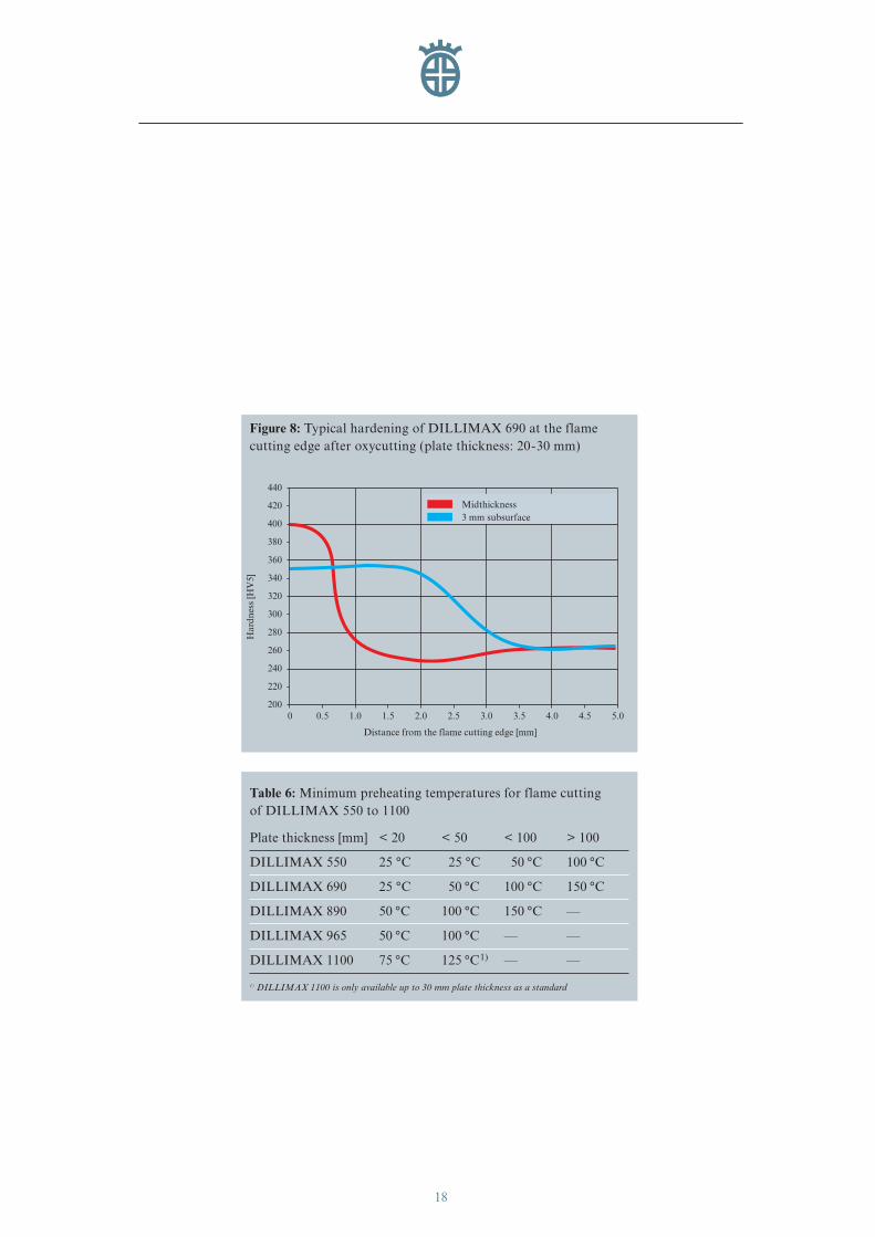
Figure 8 shows typical hardnesscurves of a DILLIMAX 690grade in the heat-affected zone(HAZ) of the flame cutting edge.
For DILLIMAX 550 to 1100, we recommend adherence tocertain minimum preheatingtemperatures for flame cutting(see Table 6).
eng_01-52_0849_dihd_max.411 04.04.2007 8:37 Uhr Seite 17
18
Table 6: Minimum preheating temperatures for flame cutting of DILLIMAX 550 to 1100
Plate thickness [mm] < 20 < 50 < 100 > 100
DILLIMAX 550 25 °C 25 °C 50 °C 100 °C
DILLIMAX 690 25 °C 50 °C 100 °C 150 °C
DILLIMAX 890 50 °C 100 °C 150 °C —
DILLIMAX 965 50 °C 100 °C — —
DILLIMAX 1100 75 °C 125 °C1) — —
1) DILLIMAX 1100 is only available up to 30 mm plate thickness as a standard
440
0
Distance from the flame cutting edge [mm]
Har
dnes
s [H
V5]
420
400
380
360
340
320
300
280
260
240
220
2000.5 1.0 1.5 2.0 2.5 3.0 3.5 4.0 4.5 5.0
Midthickness3 mm subsurface
Figure 8: Typical hardening of DILLIMAX 690 at the flamecutting edge after oxycutting (plate thickness: 20-30 mm)
eng_01-52_0849_dihd_max.411 04.04.2007 8:37 Uhr Seite 18
19
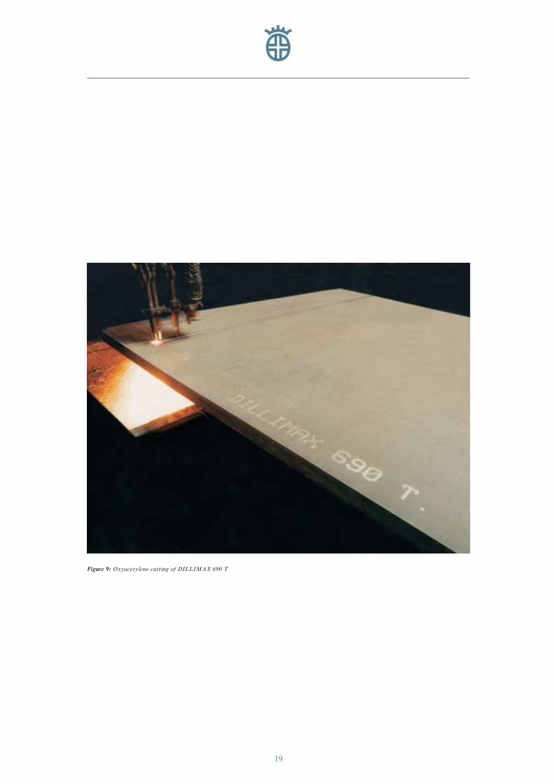
Figure 9: Oxyacetylene cutting of DILLIMAX 690 T
eng_01-52_0849_dihd_max.411 04.04.2007 8:37 Uhr Seite 19
20
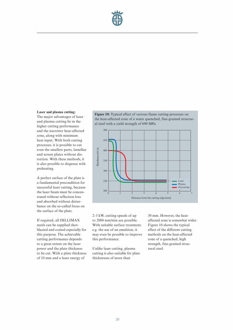
Laser and plasma cutting:The major advantages of laserand plasma cutting lie in thehigher cutting performance and the narrower heat-affected zone, along with minimum heat input. With both cuttingprocesses, it is possible to cuteven the smallest parts, lamellaeand screen plates without dis-tortion. With these methods, itis also possible to dispense withpreheating.
A perfect surface of the plate isa fundamental precondition forsuccessful laser cutting, becausethe laser beam must be concen-trated without reflection lossand absorbed without distur-bance on the so-called focus onthe surface of the plate.
If required, all DILLIMAXsteels can be supplied shot-blasted and coated especially forthis purpose. The achievablecutting performance depends to a great extent on the laserpower and the plate thickness to be cut. With a plate thicknessof 10 mm and a laser energy of
2-3 kW, cutting speeds of up to 2000 mm/min are possible.With suitable surface treatment,e.g. the use of an emulsion, itmay even be possible to improvethis performance.
Unlike laser cutting, plasmacutting is also suitable for platethicknesses of more than
30 mm. However, the heat-affected zone is somewhat wider.Figure 10 shows the typicaleffect of the different cuttingmethods on the heat-affectedzone of a quenched, highstrength, fine-grained struc-tural steel.
Figure 10: Typical effect of various flame cutting processes on the heat-affected zone of a water quenched, fine-grained structur-al steel with a yield strength of 690 MPa
0
Distance from the cutting edge [mm]
Har
dnes
s [H
V10
]
250
300
350
400
450
500
2001 2 3 4 5 6 7
LaserPlasmaOxycutting
eng_01-52_0849_dihd_max.411 04.04.2007 8:37 Uhr Seite 20
21
Welding
Weldability: DILLIMAX steelsare suitable for welding if thegeneral welding regulations (EN 1011, see section “Litera-ture”, p. 44) and the followingadvice are observed. Submergedarc welding can be carried outfor grades up to DILLIMAX 690,manual arc welding for gradesup to DILLIMAX 890, and gasshielded arc welding for gradesup to DILLIMAX 1100.
As the yield strength increases,particular care should be takenduring processing, especially inthe case of heat input duringwelding.
DILLINGER HÜTTE GTSpoints out that the followingrecommendations for weldingare purely for information. Thewide variety of welding condi-tions, the construction and theconsumables used have a signifi-
cant effect on the quality of thewelded joints. Since the respec-tive operating and processing con-ditions are not known, it is notpossible to guarantee in advancethe mechanical properties of theweld or the lack of defects in theweld. However, DILLINGERHÜTTE GTS predicts goodresults, if suitable conditions forwelding are provided.
Preparation of the weld seam:The weld seam can be preparedby machining or by thermalcutting. At the beginning of thewelding process, the seam mustbe bright, dry and free fromflame cutting slag, rust, scale,paint and any other impurities.
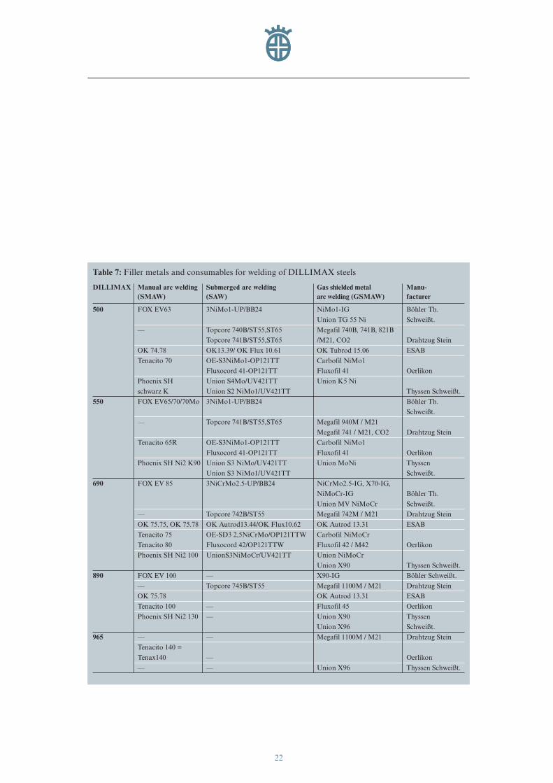
Filler metals and consumables:The filler metals must be select-ed according to the requiredmechanical properties. Since theweld metal may mix with thebase material, root welds can becreated with fillers which pro-
duce a “softer” weld metal thanthe associated filler and cappasses. The same applies to filletwelds which are not subjected to full load – in this case, too, itis often possible to use “softer”fillers by increasing the weldthickness. Basic-coated rod elec-trodes are principally used inmanual arc welding for reasonsof toughness. Basic-coated rodelectrodes possesses two out-standing properties: the impactenergy of the weld metal is high-er, especially at low tempera-tures, and the amount of hydro-gen introduced is lower thanwith any other type of coating.
Drying and storage must be car-ried out according to the manu-facturer’s instructions. With thesame considerations in mind,only basic powders should beused for submerged arc welding.
A summary of suitable weldfillers is shown in Table 7.
eng_01-52_0849_dihd_max.411 04.04.2007 8:37 Uhr Seite 21
22
Table 7: Filler metals and consumables for welding of DILLIMAX steels
DILLIMAX Manual arc welding Submerged arc welding Gas shielded metal Manu-(SMAW) (SAW) arc welding (GSMAW) facturer
500 FOX EV63 3NiMo1-UP/BB24 NiMo1-IG Böhler Th.
Union TG 55 Ni Schweißt.
–– Topcore 740B/ST55,ST65 Megafil 740B, 741B, 821B
Topcore 741B/ST55,ST65 /M21, CO2 Drahtzug Stein
OK 74.78 OK13.39/ OK Flux 10.61 OK Tubrod 15.06 ESAB
Tenacito 70 OE-S3NiMo1-OP121TT Carbofil NiMo1
Fluxocord 41-OP121TT Fluxofil 41 Oerlikon
Phoenix SH Union S4Mo/UV421TT Union K5 Ni
schwarz K Union S2 NiMo1/UV421TT Thyssen Schweißt.
550 FOX EV65/70/70Mo 3NiMo1-UP/BB24 Böhler Th.
Schweißt.
–– Topcore 741B/ST55,ST65 Megafil 940M / M21
Megafil 741 / M21, CO2 Drahtzug Stein
Tenacito 65R OE-S3NiMo1-OP121TT Carbofil NiMo1
Fluxocord 41-OP121TT Fluxofil 41 Oerlikon
Phoenix SH Ni2 K90 Union S3 NiMo/UV421TT Union MoNi Thyssen
Union S3 NiMo1/UV421TT Schweißt.
690 FOX EV 85 3NiCrMo2.5-UP/BB24 NiCrMo2.5-IG, X70-IG,
NiMoCr-IG Böhler Th.
Union MV NiMoCr Schweißt.
–– Topcore 742B/ST55 Megafil 742M / M21 Drahtzug Stein
OK 75.75, OK 75.78 OK Autrod13.44/OK Flux10.62 OK Autrod 13.31 ESAB
Tenacito 75 OE-SD3 2,5NiCrMo/OP121TTW Carbofil NiMoCr
Tenacito 80 Fluxocord 42/OP121TTW Fluxofil 42 / M42 Oerlikon
Phoenix SH Ni2 100 UnionS3NiMoCr/UV421TT Union NiMoCr
Union X90 Thyssen Schweißt.
890 FOX EV 100 –– X90-IG Böhler Schweißt.
–– Topcore 745B/ST55 Megafil 1100M / M21 Drahtzug Stein
OK 75.78 OK Autrod 13.31 ESAB
Tenacito 100 –– Fluxofil 45 Oerlikon
Phoenix SH Ni2 130 –– Union X90 Thyssen
Union X96 Schweißt.
965 –– –– Megafil 1100M / M21 Drahtzug Stein
Tenacito 140 =
Tenax140 –– Oerlikon
–– –– Union X96 Thyssen Schweißt.
eng_01-52_0849_dihd_max.411 04.04.2007 8:37 Uhr Seite 22
23
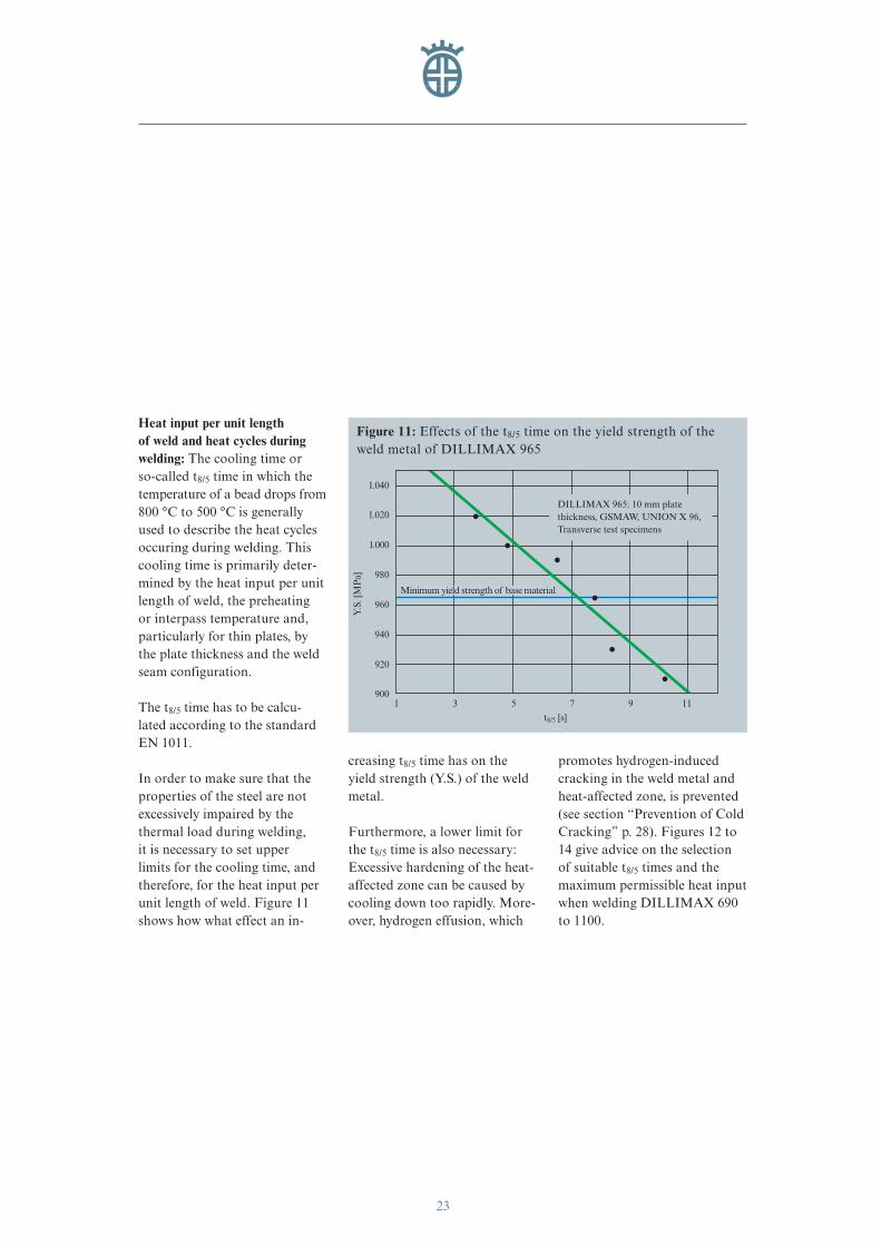
Heat input per unit length of weld and heat cycles duringwelding: The cooling time or so-called t8/5 time in which thetemperature of a bead drops from800 °C to 500 °C is generallyused to describe the heat cyclesoccuring during welding. Thiscooling time is primarily deter-mined by the heat input per unitlength of weld, the preheating or interpass temperature and,particularly for thin plates, bythe plate thickness and the weldseam configuration.
The t8/5 time has to be calcu-lated according to the standard EN 1011.
In order to make sure that theproperties of the steel are notexcessively impaired by thethermal load during welding, it is necessary to set upper limits for the cooling time, andtherefore, for the heat input perunit length of weld. Figure 11shows how what effect an in-
creasing t8/5 time has on theyield strength (Y.S.) of the weldmetal.
Furthermore, a lower limit forthe t8/5 time is also necessary:Excessive hardening of the heat-affected zone can be caused bycooling down too rapidly. More-over, hydrogen effusion, which
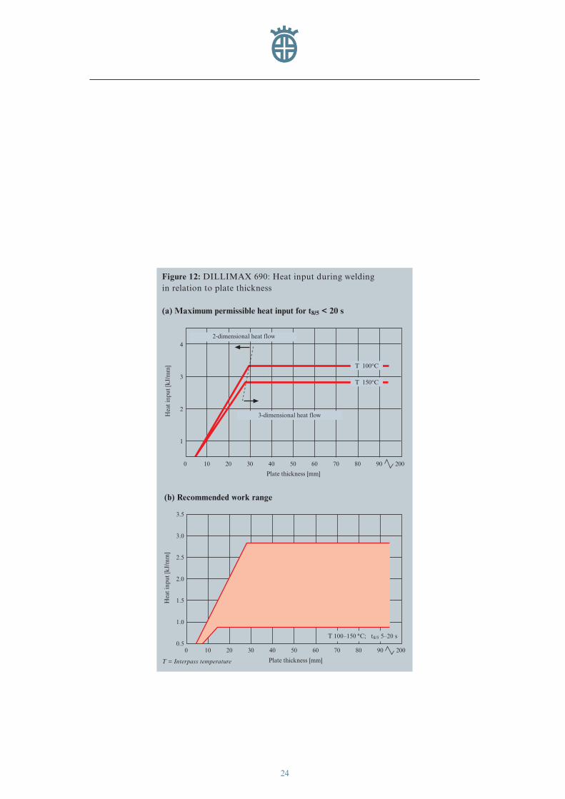
promotes hydrogen-inducedcracking in the weld metal andheat-affected zone, is prevented(see section “Prevention of ColdCracking” p. 28). Figures 12 to14 give advice on the selectionof suitable t8/5 times and themaximum permissible heat inputwhen welding DILLIMAX 690to 1100.
1.040
1.020
1.000
960
940
920
9001 3 5 7
Y.S
. [M
Pa] 980
t8/5 [s]
9 11
Minimum yield strength of base material
Figure 11: Effects of the t8/5 time on the yield strength of theweld metal of DILLIMAX 965
DILLIMAX 965: 10 mm plate thickness, GSMAW, UNION X 96,Transverse test specimens
eng_01-52_0849_dihd_max.411 04.04.2007 8:37 Uhr Seite 23
24
T 150°C
T 100°C
4
3
2
0 10 3020
Plate thickness [mm]
20070 908040 6050
Hea
t in
put
[kJ/
mm
]
2-dimensional heat flow
1
3-dimensional heat flow
3.5
3.0
2.5
2.0
1.5
1.0
0.50 10 3020
Plate thickness [mm]
20070 908040 6050
Hea
t in
put
[kJ/
mm
]
Figure 12: DILLIMAX 690: Heat input during welding in relation to plate thickness
(a) Maximum permissible heat input for t8/5 < 20 s
(b) Recommended work range
T = Interpass temperature
T 100–150 °C; t8/5 5–20 s
eng_01-52_0849_dihd_max.411 04.04.2007 8:37 Uhr Seite 24
25
2.5
2.0
1.5
0.50 10 3020
Plate thickness [mm]
10070 908040 6050
Hea
t in
put
[kJ/
mm
]
2-dimensional heat flow
1.0
3-dimensional heat flow
T 100°C
T 150°C
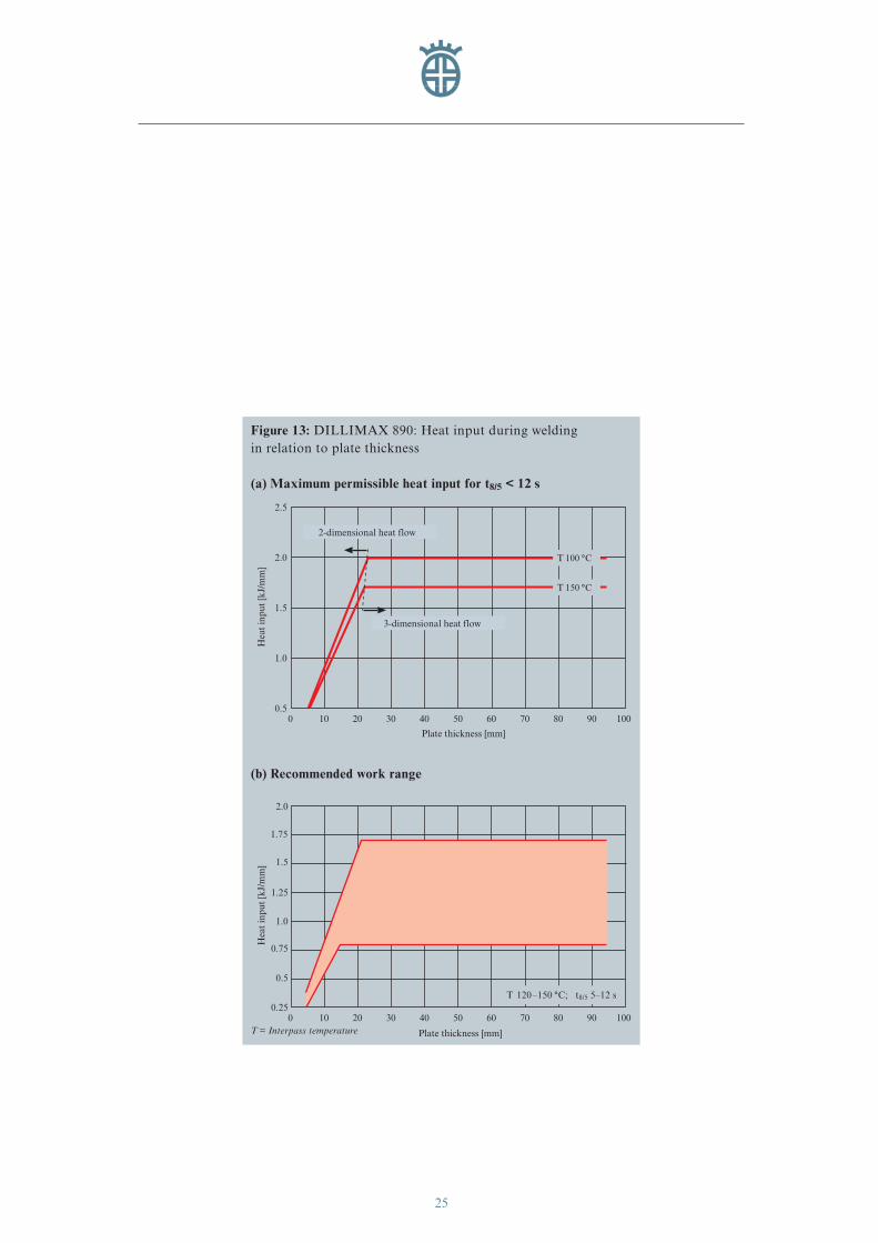
Figure 13: DILLIMAX 890: Heat input during welding in relation to plate thickness
(a) Maximum permissible heat input for t8/5 < 12 s
2.0
1.5
1.25
1.0
0.75
0.5
0.250 10 3020
Plate thickness [mm]
10070 908040 6050
Hea
t in
put
[kJ/
mm
]
1.75
(b) Recommended work range
T = Interpass temperature
T 120–150 °C; t8/5 5–12 s
T 100 °C
T 150 °C
eng_01-52_0849_dihd_max.411 04.04.2007 8:37 Uhr Seite 25
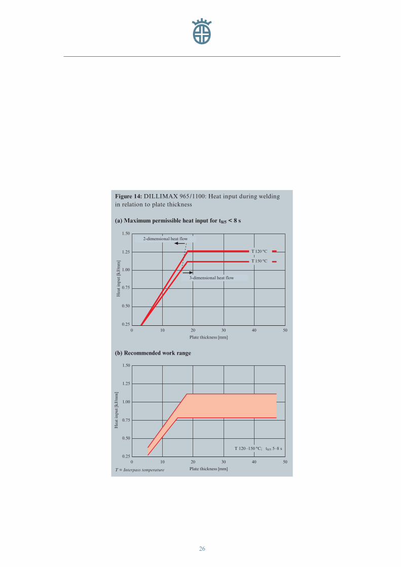
26
1.50
1.25
1.00
0 10
Plate thickness [mm]
504020 30
Hea
t in
put
[kJ/
mm
]
0.50
0.75
0.25
2-dimensional heat flow
3-dimensional heat flow
T 150°C
T 120°C
Figure 14: DILLIMAX 965 /1100: Heat input during welding in relation to plate thickness
(a) Maximum permissible heat input for t8/5 < 8 s
1.50
1.25
1.00
0 10
Plate thickness [mm]
504020 30
Hea
t in
put
[kJ/
mm
]
0.75
0.25
0.50
(b) Recommended work range
T = Interpass temperature
T 120–150 °C; t8/5 5–8 s
T 120 °C
T 150 °C
eng_01-52_0849_dihd_max.411 04.04.2007 8:37 Uhr Seite 26
27
Figure 15: Roof structure of the Sony-Center in Berlin, with DILLIMAX 690 straps for carrying beams, rope spreading and rope anchoring plates(Illustration used with the kind permission of Waagner-Biró AG, Wien, Austria)
rope spreading plates
rope anchoring plates
eng_01-52_0849_dihd_max.411 04.04.2007 8:37 Uhr Seite 27
28
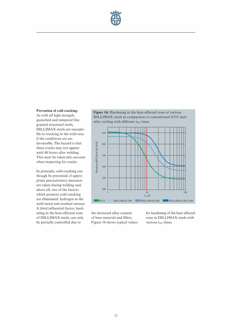
Prevention of cold cracking:As with all high strength,quenched and tempered finegrained structural steels,DILLIMAX steels are suscepti-ble to cracking in the weld areaif the conditions are un-favourable. The hazard is thatthese cracks may not appearuntil 48 hours after welding.This must be taken into accountwhen inspecting for cracks.
In principle, cold cracking canthough be prevented, if appro-priate precautionary measuresare taken during welding and,above all, two of the factorswhich promote cold crackingare eliminated: hydrogen in theweld metal and residual stresses.A third influential factor, hard-ening in the heat-affected zoneof DILLIMAX steels, can onlybe partially controlled due to
the increased alloy content of base material and fillers. Figure 16 shows typical values
for hardening of the heat affectedzone in DILLIMAX steels withvarious t8/5 times.
450
10t8/5 [s]
Har
dnes
s [H
V10
] in
the
HA
Z
400
350
300
250
2001 100
Figure 16: Hardening in the heat-affected zone of variousDILLIMAX steels in comparison to conventional S355 steelafter cooling with different t8/5 times
S355 DILLIMAX 500 DILLIMAX 690 DILLIMAX 965/1100
eng_01-52_0849_dihd_max.411 04.04.2007 8:37 Uhr Seite 28
29
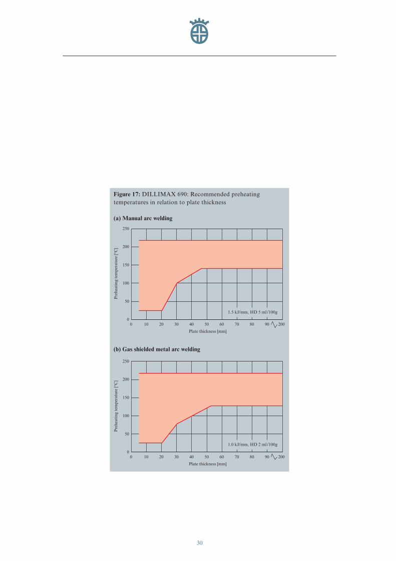
Deposits of molecular hydrogenat the grain boundaries of theweld metal structure and on thefusion line are the main causesof cracking. The hydrogenenters the weld through moistweld fillers, films of moisture onthe weld edges or the atmos-phere surrounding the arc. It can be avoided by selectingsuitable weld fillers, keepingthem dry in storage and aboveall by preheating the componentto be welded.
Preheating leads to a delay inthe cooling of the componentafter welding, which means thatthe hydrogen has enough timeto diffuse out. This phenome-non mainly takes place in thetemperature range between 300 °C and 100 °C.
Preheating not only refers to the heating of the weld area at
the beginning of the weldingprocess, it also means adherenceto a certain minimum tempera-ture throughout the wholewelding process (interpass tem-perature). The preheated areashould extend to at least 100 mmon either side of the seam.
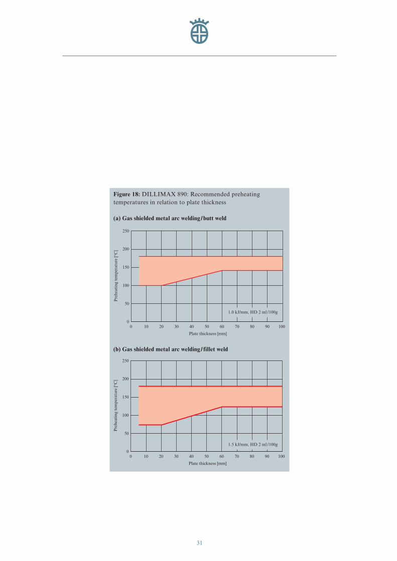
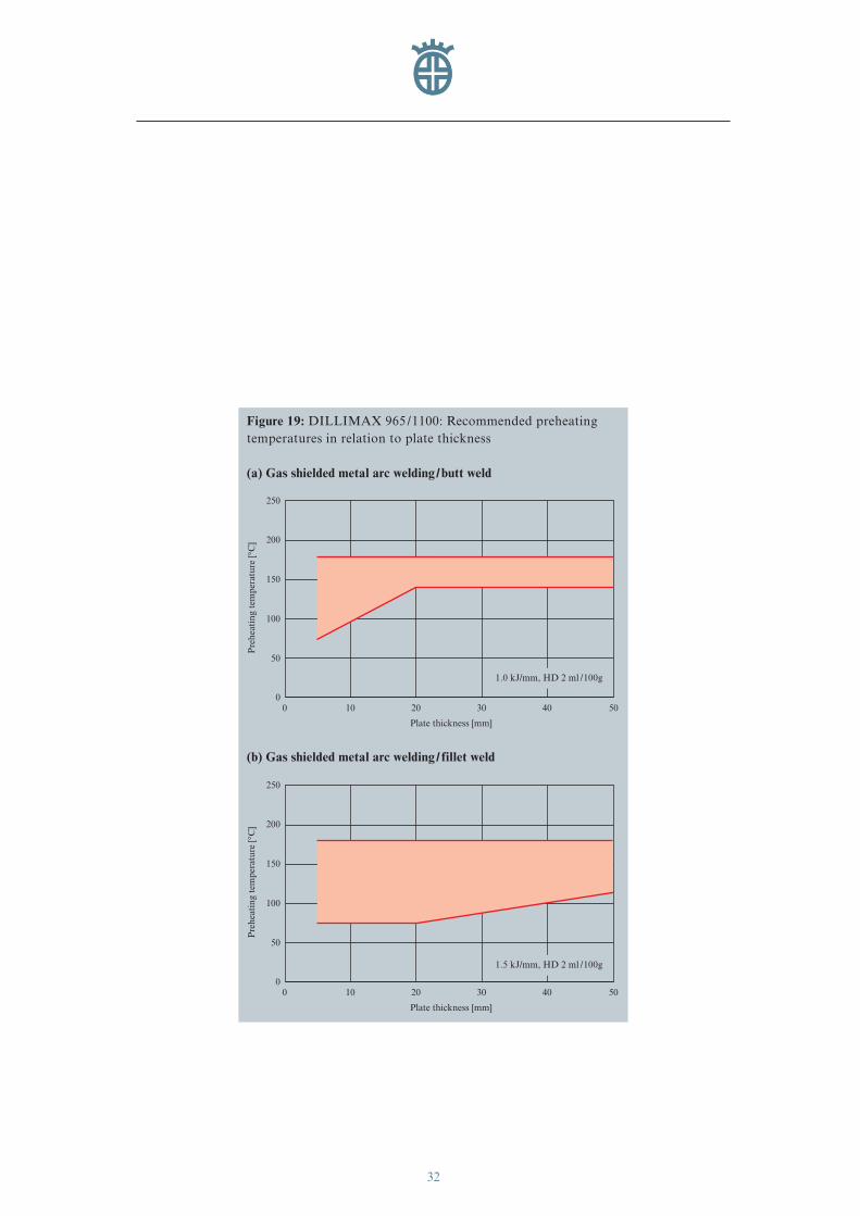
Recommended preheating tem-peratures for DILLIMAX 690to 1100 are given in Figures 17 to 19.
For plate thickness above 30 mm,as well as welding techniqueswhich introduce a large amountof hydrogen into the workpiece(e.g. submerged-arc welding), it is advisable to carry out low-hydrogen annealing at 200 °Cimmediately after welding. The annealing time depends on the thickness of the compo-nent and should not be shorterthan two hours.
The risk of cracking occurring inwelded joints as a result of resid-ual stresses is particularly greatfor an only partially filled seamcross-section. Therefore, coolingdown below the prescribed inter-pass temperature must be avoid-ed during the entire weldingprocess. To keep residual stressas low as possible, harsh cross-sectional transitions and concen-tration of welds must be avoided.
Make sure as well that the com-ponents to be welded form agood fit and that the welds arefree from notches as far as pos-sible. An advantageous weldsequence can also reduce thelevel of residual stresses.
Basically, the weld sequenceshould be selected to ensurethat the individual componentscan shrink freely for as long aspossible.
eng_01-52_0849_dihd_max.411 04.04.2007 8:37 Uhr Seite 29
30
250
200
100
50
00 10 3020
Plate thickness [mm]
20070 908040 6050
Pre
heat
ing
tem
pera
ture
[°C
]
150
250
200
100
50
00 10 3020
Plate thickness [mm]
20070 908040 6050
Pre
heat
ing
tem
pera
ture
[°C
]
150
Figure 17: DILLIMAX 690: Recommended preheating temperatures in relation to plate thickness
(a) Manual arc welding
(b) Gas shielded metal arc welding
1.5 kJ/mm, HD 5 ml /100g
1.0 kJ/mm, HD 2 ml /100g
eng_01-52_0849_dihd_max.411 04.04.2007 8:37 Uhr Seite 30
31
250
200
100
50
00 10 3020
Plate thickness [mm]
10070 908040 6050
Pre
heat
ing
tem
pera
ture
[°C
]
150
Figure 18: DILLIMAX 890: Recommended preheating temperatures in relation to plate thickness
(a) Gas shielded metal arc welding/butt weld
250
200
100
50
00 10 3020
Plate thickness [mm]
10070 908040 6050
Pre
heat
ing
tem
pera
ture
[°C
]
150
(b) Gas shielded metal arc welding/ fillet weld
1.0 kJ/mm, HD 2 ml /100g
1.5 kJ/mm, HD 2 ml /100g
eng_01-52_0849_dihd_max.411 04.04.2007 8:37 Uhr Seite 31
32
250
200
100
50
00 10
Plate thickness [mm]
504020 30
Pre
heat
ing
tem
pera
ture
[°C
]
150
Figure 19: DILLIMAX 965 /1100: Recommended preheatingtemperatures in relation to plate thickness
(a) Gas shielded metal arc welding/butt weld
250
200
100
50
00 10
Plate thickness [mm]
504020 30
Pre
heat
ing
tem
pera
ture
[°C
]
150
(b) Gas shielded metal arc welding/ fillet weld
1.0 kJ/mm, HD 2 ml /100g
1.5 kJ/mm, HD 2 ml /100g
eng_01-52_0849_dihd_max.411 04.04.2007 8:37 Uhr Seite 32
33
Stress Relieving
DILLIMAX steels and theirappropriately welded joints havea degree of toughness sufficientfor them to be used in highlyloaded components, in generalwithout necessity of a stressrelieving treatment.
If stress relieving is necessarydue to regulations or for con-structive reasons, the plate man-ufacturer should be consulted.
In general, the highest stressrelieving temperature should be40 °C below the temperingtemperature of the quenchingprocess. If such a heat treatmentis to be carried out by the fabri-cator, it must be specified whenordering that the respective tempering temperature atDILLINGER HÜTTE GTS has to appear on the works cer-tificate. The holding time whenannealing should not exceed 60 minutes. If longer holdingtimes are prescribed, the stressrelieving temperature is to befurther reduced in relation tothe tempering temperature. Incase of high level of residualstresses or for very thick plates,care must be taken to avoid pro-nounced differences in tempera-ture in the component while
heating up to annealing temper-ature. In case the stress relievingtemperature is laid down, i.e. the customer cannot take intoaccount the tempering tempera-ture during plate manufacturing,DILLINGER HÜTTE GTSshould be consulted as early asthe inquiry stage.
Due to their chemical composi-tion and heat treatment, DILLI-MAX steels have a relativelyhigh strength at elevated temper-atures. Their stress relief duringstress relieving is thus less com-plete than for ordinary structur-al steels.
Stress relieving of DILLIMAX1100 is not permissible.
Flame Straightening
Flame straightening of plates inthe steel construction sector is a technique often used to formcomplex components and achieveeven cross-sections. DILLIMAXsteels up to DILLIMAX 965can be flame-straightened with-out any problems. However, certain general conditions mustbe adhered to, as is the case withthe processing of conventionalsteels. A distinction is to bemade between flame straighten-ing with line heating and flame
straightening with heat spotsand triangular shaped tempera-ture fields.
Flame straightening of DILLI-MAX 1100 is not permissible.
Flame straightening with lineheating: Operational tests haveshown that no reduction in thestrength properties or impactproperties occurs with linearflame straightening of DILLI-MAX 690 up to 800 °C.
For DILLIMAX grades withhigher yield point, a drop of thetensile and toughness propertiesis to be expected in case of highheat input.
Flame straightening with heatspots and triangular temperaturefields: In comparison to flamestraightening with line heating,this method heats the entireplate cross-section, thus result-ing in detrimental longer hold-ing times at peak temperature(above the tempering tempera-ture) and longer cooling times.The flame straightening temper-ature should not exceed 650 °Cfor any of the DILLIMAXsteels up to DILLIMAX 890(for DILLIMAX 965: 600 °C).
eng_01-52_0849_dihd_max.411 04.04.2007 8:37 Uhr Seite 33
34
Galvanizing
During pickling or galvanizinghigh strength steels may have atendency to crack formation.The risk of cracks during hotgalvanizing depends not only onthe material selection, but alsoon the construction, the internalstresses, the composition of thezinc bath and the process con-trol during the galvanizing. For this reason the use of higherstrength, quenched and tempe-red steels in hot galvanized con-structions has to be handledwith a particular care. In any case the steel manufacturer andthe galvanizing plant must beconsulted.
Machining
Despite their high degree ofstrength, DILLIMAX steels areeasy to machine. However, somebasic rules have to be observedwhen machining these highstrength steels. Vibrations shouldbe avoided. It is therefore advisa-ble to work on a machine that isas rigid as possible, and to keepthe gap between the workpieceand the machine (support) to aminimum. Similarly, it is advisa-ble to fix the workpiece firmly tothe workbench.
Depending on the type of ma-chining work, sufficient coolingshould be ensured. An interrup-tion of the coolant supply orinsufficient coolants and lubri-
cants may lead to overheating of the cutting edge, which maycause increased tool wear, and in extreme cases lead to its breakage. Please note therelevant information given bythe tool manufacturer.
The recommendations given inthe following tables for the selec-tion of tools and the machiningof DILLIMAX steels are guide-lines which may lead to differentresults for different machines.The validity of these recommen-dations should be checked bythe processing specialist on site.Detailed information about ma-chining and tool selection canbe obtained by consulting toolmanufacturers or DILLINGERHÜTTE GTS.
eng_01-52_0849_dihd_max.411 04.04.2007 8:37 Uhr Seite 34
35
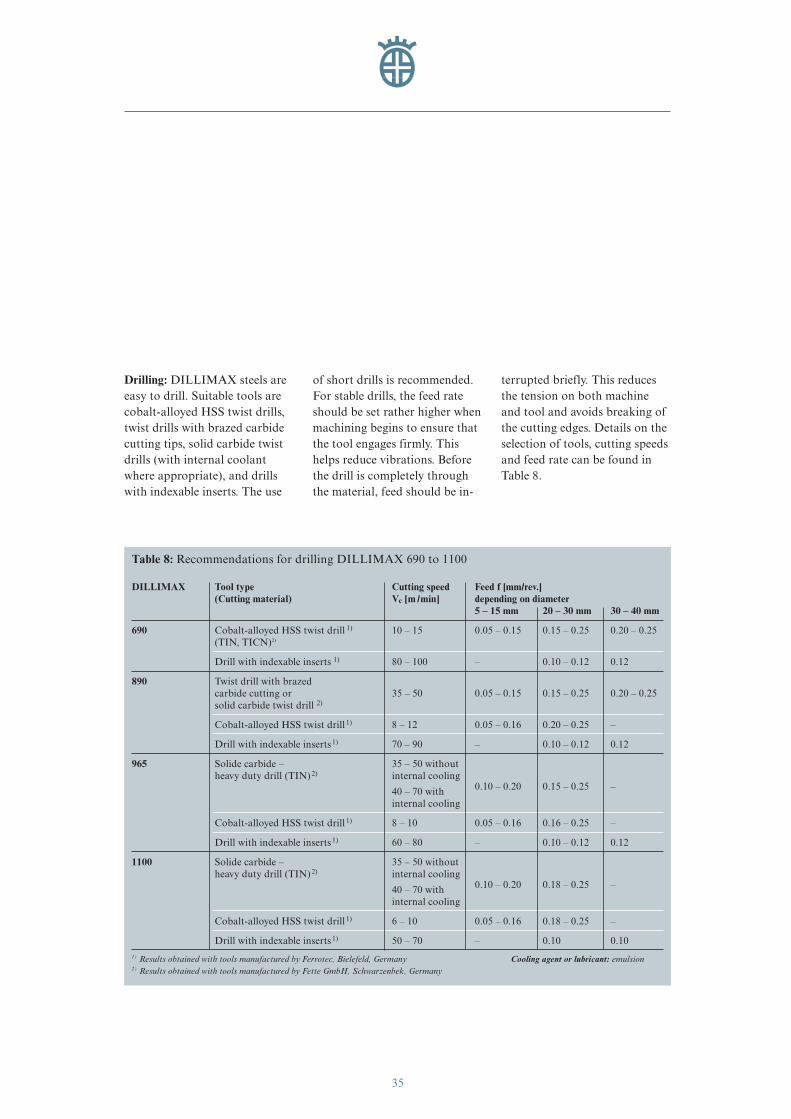
Drilling: DILLIMAX steels areeasy to drill. Suitable tools arecobalt-alloyed HSS twist drills,twist drills with brazed carbidecutting tips, solid carbide twistdrills (with internal coolantwhere appropriate), and drillswith indexable inserts. The use
of short drills is recommended.For stable drills, the feed rateshould be set rather higher whenmachining begins to ensure thatthe tool engages firmly. Thishelps reduce vibrations. Beforethe drill is completely throughthe material, feed should be in-
terrupted briefly. This reducesthe tension on both machineand tool and avoids breaking ofthe cutting edges. Details on theselection of tools, cutting speedsand feed rate can be found inTable 8.
Table 8: Recommendations for drilling DILLIMAX 690 to 1100
DILLIMAX Tool type Cutting speed Feed f [mm/rev.](Cutting material) Vc [m /min] depending on diameter
5 – 15 mm 20 – 30 mm 30 – 40 mm
690 Cobalt-alloyed HSS twist drill 1) 10 – 15 0.05 – 0.15 0.15 – 0.25 0.20 – 0.25(TIN, TICN)2)
Drill with indexable inserts 1) 80 – 100 – 0.10 – 0.12 0.12
890 Twist drill with brazedcarbide cutting or 35 – 50 0.05 – 0.15 0.15 – 0.25 0.20 – 0.25solid carbide twist drill 2)
Cobalt-alloyed HSS twist drill 1) 8 – 12 0.05 – 0.16 0.20 – 0.25 –
Drill with indexable inserts 1) 70 – 90 – 0.10 – 0.12 0.12
965 Solide carbide – 35 – 50 withoutheavy duty drill (TIN) 2) internal cooling
0.10 – 0.20 0.15 – 0.25 –40 – 70 withinternal cooling
Cobalt-alloyed HSS twist drill 1) 8 – 10 0.05 – 0.16 0.16 – 0.25 –
Drill with indexable inserts 1) 60 – 80 – 0.10 – 0.12 0.12
1100 Solide carbide – 35 – 50 withoutheavy duty drill (TIN) 2) internal cooling
0.10 – 0.20 0.18 – 0.25 –40 – 70 withinternal cooling
Cobalt-alloyed HSS twist drill 1) 6 – 10 0.05 – 0.16 0.18 – 0.25 –
Drill with indexable inserts 1) 50 – 70 – 0.10 0.101) Results obtained with tools manufactured by Ferrotec, Bielefeld, Germany Cooling agent or lubricant: emulsion2) Results obtained with tools manufactured by Fette GmbH, Schwarzenbek, Germany
eng_01-52_0849_dihd_max.411 04.04.2007 8:37 Uhr Seite 35
36
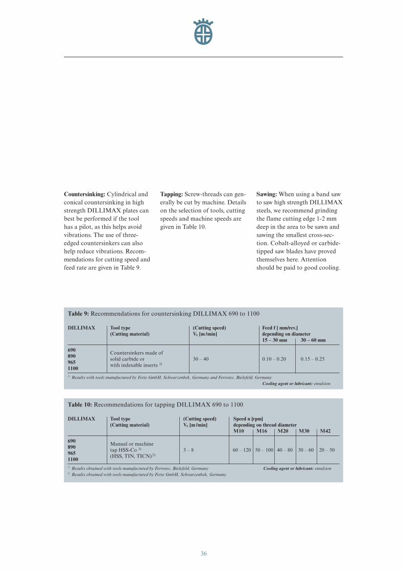
Countersinking: Cylindrical andconical countersinking in highstrength DILLIMAX plates canbest be performed if the tool has a pilot, as this helps avoid vibrations. The use of three-edged countersinkers can alsohelp reduce vibrations. Recom-mendations for cutting speed andfeed rate are given in Table 9.
Tapping: Screw-threads can gen-erally be cut by machine. Detailson the selection of tools, cuttingspeeds and machine speeds aregiven in Table 10.
Sawing: When using a band sawto saw high strength DILLIMAXsteels, we recommend grindingthe flame cutting edge 1-2 mmdeep in the area to be sawn andsawing the smallest cross-sec-tion. Cobalt-alloyed or carbide-tipped saw blades have provedthemselves here. Attentionshould be paid to good cooling.
Table 9: Recommendations for countersinking DILLIMAX 690 to 1100
DILLIMAX Tool type (Cutting speed) Feed f [ mm/rev.](Cutting material) Vc [m /min] depending on diameter
15 – 30 mm 30 – 60 mm
690 Countersinkers made of 890 solid carbide or 30 – 40 0.10 – 0.20 0.15 – 0.25965 with indexable inserts 1)11001) Results with tools manufactured by Fette GmbH, Schwarzenbek, Germany and Ferrotec, Bielefeld, Germany
Cooling agent or lubricant: emulsion
Table 10: Recommendations for tapping DILLIMAX 690 to 1100
DILLIMAX Tool type (Cutting speed) Speed n [rpm] (Cutting material) Vc [m /min] depending on thread diameter
M10 M16 M20 M30 M42
690 Manual or machine890 tap HSS-Co 1) 3 – 8 60 – 120 50 – 100 40 – 80 30 – 60 20 – 50965 (HSS, TIN, TICN) 2)11001) Results obtained with tools manufactured by Ferrotec, Bielefeld, Germany Cooling agent or lubricant: emulsion2) Results obtained with tools manufactured by Fette GmbH, Schwarzenbek, Germany
eng_01-52_0849_dihd_max.411 04.04.2007 8:37 Uhr Seite 36
37
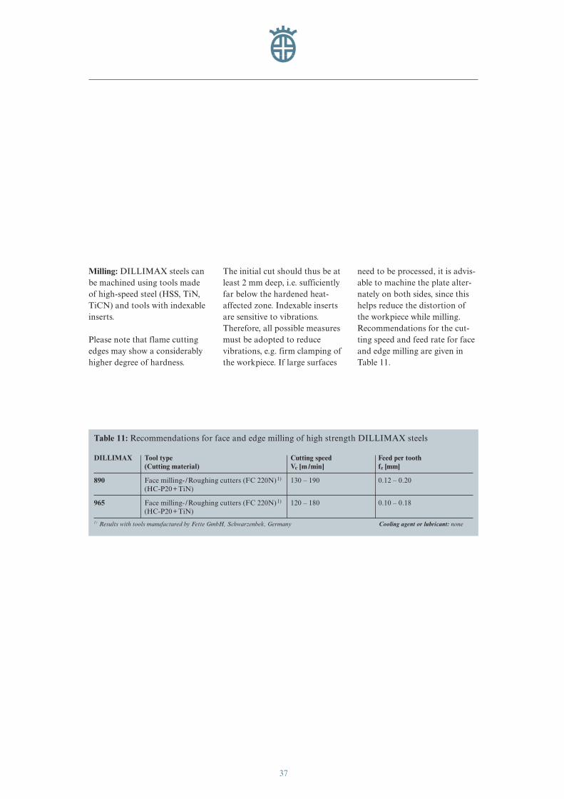
Milling: DILLIMAX steels canbe machined using tools madeof high-speed steel (HSS, TiN,TiCN) and tools with indexableinserts.
Please note that flame cuttingedges may show a considerablyhigher degree of hardness.
The initial cut should thus be atleast 2 mm deep, i.e. sufficientlyfar below the hardened heat-affected zone. Indexable insertsare sensitive to vibrations.Therefore, all possible measuresmust be adopted to reducevibrations, e.g. firm clamping ofthe workpiece. If large surfaces
need to be processed, it is advis-able to machine the plate alter-nately on both sides, since thishelps reduce the distortion ofthe workpiece while milling.Recommendations for the cut-ting speed and feed rate for faceand edge milling are given inTable 11.
Table 11: Recommendations for face and edge milling of high strength DILLIMAX steels
DILLIMAX Tool type Cutting speed Feed per tooth(Cutting material) Vc [m /min] fz [mm]
890 Face milling- /Roughing cutters (FC 220N) 1) 130 – 190 0.12 – 0.20(HC-P20+TiN)
965 Face milling- /Roughing cutters (FC 220N) 1) 120 – 180 0.10 – 0.18(HC-P20+TiN)
1) Results with tools manufactured by Fette GmbH, Schwarzenbek, Germany Cooling agent or lubricant: none
eng_01-52_0849_dihd_max.411 04.04.2007 8:37 Uhr Seite 37
38
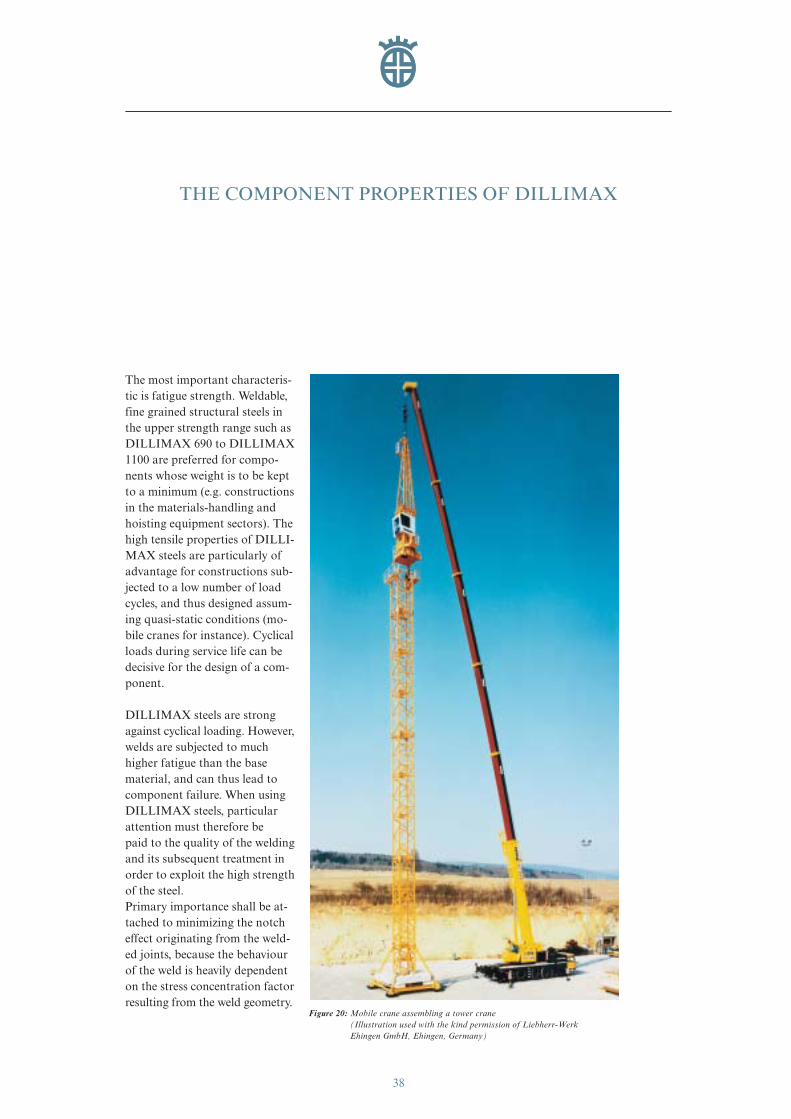
The most important characteris-tic is fatigue strength. Weldable,fine grained structural steels inthe upper strength range such asDILLIMAX 690 to DILLIMAX1100 are preferred for compo-nents whose weight is to be keptto a minimum (e.g. constructionsin the materials-handling andhoisting equipment sectors). Thehigh tensile properties of DILLI-MAX steels are particularly ofadvantage for constructions sub-jected to a low number of loadcycles, and thus designed assum-ing quasi-static conditions (mo-bile cranes for instance). Cyclicalloads during service life can bedecisive for the design of a com-ponent.
DILLIMAX steels are strongagainst cyclical loading. However,welds are subjected to muchhigher fatigue than the basematerial, and can thus lead tocomponent failure. When usingDILLIMAX steels, particularattention must therefore be paid to the quality of the weldingand its subsequent treatment inorder to exploit the high strengthof the steel.Primary importance shall be at-tached to minimizing the notcheffect originating from the weld-ed joints, because the behaviourof the weld is heavily dependenton the stress concentration factorresulting from the weld geometry.
THE COMPONENT PROPERTIES OF DILLIMAX
Figure 20: Mobile crane assembling a tower crane(Illustration used with the kind permission of Liebherr-WerkEhingen GmbH, Ehingen, Germany)
eng_01-52_0849_dihd_max.411 04.04.2007 8:37 Uhr Seite 38
39
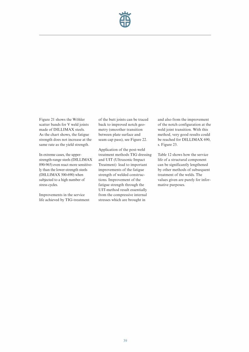
Figure 21 shows the Wöhlerscatter bands for V weld jointsmade of DILLIMAX steels. As the chart shows, the fatiguestrength does not increase at thesame rate as the yield strength.
In extreme cases, the upper-strength-range steels (DILLIMAX890-965) even react more sensitive-ly than the lower-strength steels(DILLIMAX 500-690) when subjected to a high number ofstress cycles.
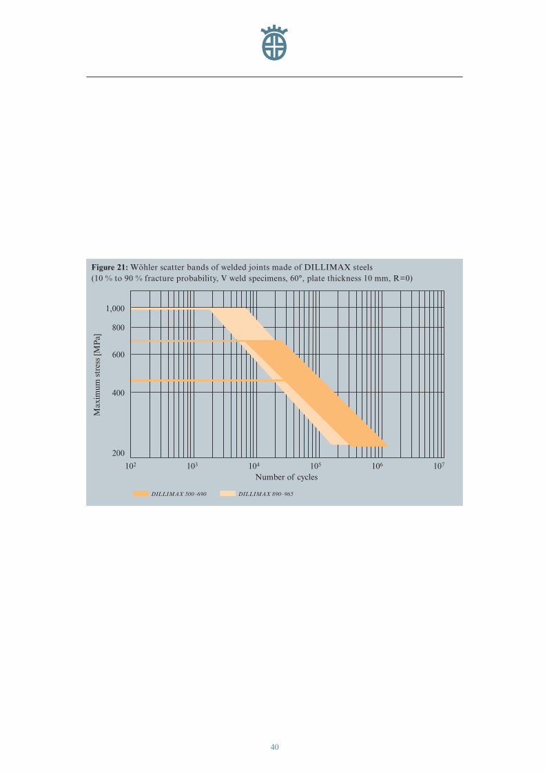
Improvements in the service life achieved by TIG-treatment
of the butt joints can be tracedback to improved notch geo-metry (smoother transition between plate surface and seam cap pass), see Figure 22.
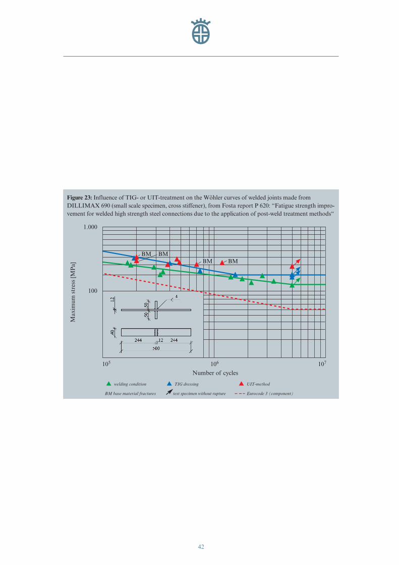
Application of the post-weldtreatment methods TIG dressingand UIT (Ultrasonic ImpactTreatment) lead to importantimprovements of the fatiguestrength of welded construc-tions. Improvement of the fatigue strength through theUIT-method result essentiallyfrom the compressive internalstresses which are brought in
and also from the improvementof the notch configuration at theweld joint transition. With thismethod, very good results couldbe reached for DILLIMAX 690, s. Figure 23.
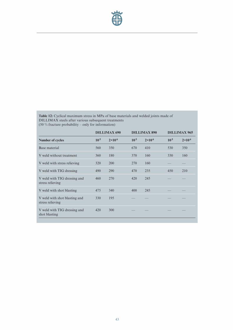
Table 12 shows how the servicelife of a structural componentcan be significantly lengthenedby other methods of subsequenttreatment of the welds. The values given are purely for infor-mative purposes.
eng_01-52_0849_dihd_max.411 04.04.2007 8:37 Uhr Seite 39
40
1,000
Number of cycles
Max
imum
str
ess
[MP
a]
800
600
400
200
102 103 104 105 106 107
Figure 21: Wöhler scatter bands of welded joints made of DILLIMAX steels (10 % to 90 % fracture probability, V weld specimens, 60°, plate thickness 10 mm, R=0)
DILLIMAX 500–690 DILLIMAX 890–965
eng_01-52_0849_dihd_max.411 04.04.2007 8:37 Uhr Seite 40
41
1,000
Number of cycles
Max
imum
str
ess
[MP
a]
800
600
400
200
102 103 104 105 106 107
Figure 22: Influence of TIG treatment on the Wöhler scatter bands of welded joints made ofDILLIMAX 890/965 (10 % to 90 % fracture probability, R=0)
TIG-treated Untreated
eng_01-52_0849_dihd_max.411 04.04.2007 8:37 Uhr Seite 41
42
1.000
106
Number of cycles
Max
imum
str
ess
[MP
a]
100
105 107
BM BMBM BM
Figure 23: Influence of TIG- or UIT-treatment on the Wöhler curves of welded joints made from DILLIMAX 690 (small scale specimen, cross stiffener), from Fosta report P 620: “Fatigue strength impro-vement for welded high strength steel connections due to the application of post-weld treatment methods“
▲ welding condition ▲ TIG dressing ▲ UIT-method
BM base material fractures test specimen without rupture Eurocode 3 (component)
eng_01-52_0849_dihd_max.411 04.04.2007 8:37 Uhr Seite 42
43
Table 12: Cyclical maximum stress in MPa of base materials and welded joints made of DILLIMAX steels after various subsequent treatments (50 % fracture probability – only for information)
DILLIMAX 690 DILLIMAX 890 DILLIMAX 965
Number of cycles 10 5 2 •10 6 10 5 2 •10 6 10 5 2 •10 6
Base material 560 350 670 410 530 350
V weld without treatment 360 180 370 160 330 160
V weld with stress relieving 320 200 270 160 — —
V weld with TIG dressing 490 290 470 235 450 210
V weld with TIG dressing and 460 270 420 245 — —stress relieving
V weld with shot blasting 475 340 400 245 — —
V weld with shot blasting and 330 195 — — — —stress relieving
V weld with TIG dressing and 420 300 — — — —shot blasting
eng_01-52_0849_dihd_max.411 04.04.2007 8:37 Uhr Seite 43
44
Additional reading for the section“Weight-Watching for your SteelStructures“
Auvigne J.F.: Un exemple indus-triel d’allègement par l’emploides HLE: Cas des grues mobilesPPM, Tôles en acier HLE –Choix et mise en œuvre, Jounées organisées par le CE-TIM, l’OTUA et le CNISF, 30 March 1994, pp. 57-63
Nimal F.: Participation desaciers HLE dans l’allègementdes pièces mécaniques creusesfaites à partir de tôles – Bilanéconomique, Tôles en acier HLE – Choix et mise en œuvre,Jounées organisées par le CETIM, l’OTUA et le CNISF, 30 March 1994, pp. 65-75
EN 10025-6 (11/2004): Hotrolled products of structuralsteels – Part 6: Technical delivery conditions for flat products of high yield strengthstructural steels in the quenchedand tempered condition, CEN
Allgemeine bauaufsichtliche Zulassung Nr. Z-30.1-1: Flacherzeugnisse aus hoch-festem schweißgeeignetem Feinkornbaustahl S690QL1 und die daraus hergestelltenBauteile. Deutsches Institut fürBautechnik, Berlin, Januar 2005
prEN 1993-1-12: 2005 Eurocode 3: Design of steelstructures – Part 1.12: Additio-nal rules for the extension of EN 1993 up to steel grades S700,CEN, 2005
EN 10028-6 (06/2003): Flat pro-ducts made of steels for pressurepurposes – Part 6: Weldable finegrain steels, quenched and tem-pered, CEN
Additional reading for the section“The Processing of DILLIMAX“
Bouhelier C.: Le formage destôles fortes, CETIM, 1982
EN 1011 (Part 1: 05/2002, Part 2: 01/2001): Recommen-dations for welding of metallicmaterials, CEN
Uwer D. et al.: Schweißenmoderner hochfester Baustähle,Stahl u. Eisen 112 (1192) 4, pp. 29-35
Thiele W.-R.: Gefüge vonhochfesten Feinkornbaustählennach Flammrichtvorgängen.Linde AG Sonderdruck 114.Linde AG Werksgruppe-Tech-nische Gase, Höllriegelskreuth
LITERATURE
eng_01-52_0849_dihd_max.411 04.04.2007 8:37 Uhr Seite 44
45
Osama A. K.: Flammrichtenvon schweißgeeigneten Vergü-tungsstählen mit niedrigemKohlenstoffgehalt, Schweißenund Schneiden 35 (1983) 5, pp. 216-219
Nieß M. et al.: Auswirkungendes Flammrichtens auf diemechanischen Gütewerte vonhochfesten Feinkornbaustählen.DVS-Berichte Band 112. DVS-Verlag, Düsseldorf, 1988
Beratung Feuerverzinken:Arbeitsblätter “Feuerverzinken“,Institut Feuerverzinken GmbH,Düsseldorf, 1996
Additional reading for the section“The Component Properties ofDILLIMAX“
Ring M. et al.: Fatigue propertiesof laser-beam weldments onhigh strength steels, Steel Re-search 65 (1994) 11, pp. 505-510
Fischer F. et al.: Rißeinleitungs-und Rißausbreitungswiderstandhochfester Baustähle bei stati-scher Beanspruchung, Stahl undEisen 114 (1994) 11, pp. 125-128
Hübner P. et al.: MAG-Schweißverbindungen des StahlsStE 885 bei statischer, dynami-scher und zyklischer Beanspru-chung, Stahl und Eisen 115(1195) 7, pp. 81-86
Hübner P. et al.: Schwingfes-tigkeit der hochfesten schweiß-baren Baustähle StE 885 undStE 960. Dissertation. TechnischeUniversität Freiberg, 1996
Franke S. et al.: Einfluß vonStrukturparametern auf stati-sche und zyklische Bruch-zähigkeitskennwerte. BerichtEUR 16782 DE. TechnischeForschung Stahl, 1994
U. Kuhlmann, A. Dürr, J. Bergmann, R. Thumser: Effi-zienter Stahlbau aus höherfestenStählen unter Ermüdungsbean-spruchung. ForschungsvorhabenP 620. ForschungsvereinigungStahlanwendung e.V., 2006
eng_01-52_0849_dihd_max.411 04.04.2007 8:37 Uhr Seite 45
46
Ageing ....................................................................................... 15ffBending radius ........................................................................... 12ffCarbon equivalent .......................................................................... 6Cold cracking, liability to ...................................................... 23, 28fCold forming .............................................................................. 12ffComposition, chemical.................................................................... 6Cooling time .............................................................................. 23ffCountersinking ............................................................................. 36Die opening ............................................................................... 12ffDrilling ........................................................................................ 35Fatigue properties ....................................................................... 38ff Filler metals ................................................................................ 21fFlame cutting ............................................................................. 17ffFlame straightening ...................................................................... 33Elongation .................................................................................... 8fGalvanizing .................................................................................. 34Gas shielded metal arc welding............................................. 21f, 30ffHeat-affected zone ................................................................. 17f, 20Heat input (per unit length of weld) ........................................... 23ff High-temperature strength ........................................................... 11Hot forming................................................................................. 16f Impact energy ........................................................................... 9, 15Laser cutting ................................................................................ 20 Manual arc welding .............................................................. 21, 30ffMilling ......................................................................................... 37 Preheating temperature, minimum ........................................ 18, 30ffPlasma arc cutting ........................................................................ 20Renewed quenching and tempering ............................................. 16fResidual stress ....................................................................... 28f, 37Sawing .......................................................................................... 36Stress relieving ....................................................................... 16f, 33 Submerged arc welding ............................................................... 21fTapping ........................................................................................ 36 Tempering ............................................................................... 7, 16fTensile strength ............................................................................. 8fThrough-thickness direction, properties in .................................... 11 Water quenching ............................................................................. 7Weldability ................................................................................. 21ffYield strength ................................................................................. 8
INDEX
eng_01-52_0849_dihd_max.411 04.04.2007 8:37 Uhr Seite 46
47
GermanyVertriebsgesellschaftDillinger Hütte GTS Postfach 10492770043 StuttgartTel: +49 7 11 61 46-300Fax: +49 7 11 61 46-221
FranceDILLING-GTS Ventes5, rue Luigi Cherubini93212 La Plaine Saint Denis CedexTel: +33 1 71 92 16 74Fax: +33 1 71 92 17 98
Other countriesFor your local representativeplease contact our coordinationoffice in Dillingen:
Tel: +49 68 31 47 23 85Fax: +49 68 31 47 99 24 72
SALES ORGANISATIONS
eng_01-52_0849_dihd_max.411 04.04.2007 8:37 Uhr Seite 47
48
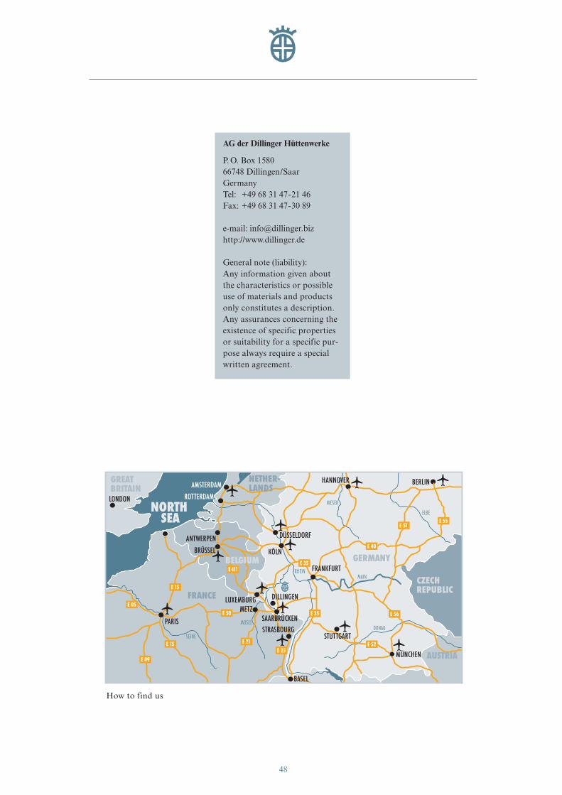
AG der Dillinger Hüttenwerke
P. O. Box 158066748 Dillingen/SaarGermanyTel: +49 68 31 47-21 46Fax: +49 68 31 47-30 89
e-mail: [email protected]://www.dillinger.de
General note (liability):Any information given aboutthe characteristics or possibleuse of materials and productsonly constitutes a description.Any assurances concerning theexistence of specific propertiesor suitability for a specific pur-pose always require a specialwritten agreement.
How to find us
HANNOVER BERLIN
STUTTGART
MÜNCHEN
FRANKFURT
LUXEMBURG DILLINGEN
SAARBRÜCKENMETZ
STRASBOURG
BASEL
PARIS
SEINE
RHEIN
MOSELDONAU
ELBE
WESER
MAIN
E 35
E 51
E 25
E 35
E 52
E 40
E 55
E 56
E 15
E 50
E 21
E 09
E 05
E 15
E 411
AMSTERDAM
BRÜSSEL
ANTWERPEN
ROTTERDAM
DÜSSELDORF
KÖLN
FRANCE
GERMANY
GREATBRITAIN
CZECHREPUBLIC
AUSTRIA
SEANORTH
LONDON
NETHER-LANDS
BELGIUM
eng_01-52_0849_dihd_max.411 04.04.2007 8:37 Uhr Seite 48

eng_01-52_0849_dihd_max.411 04.04.2007 8:37 Uhr Seite 49

Tec
hnic
al I
nfor
mat
ion
DIL
LIM
AX
E/0
7K
DV
eng_01-52_0849_dihd_max.411 04.04.2007 8:37 Uhr Seite 50


![HIGH -TECH -MOTORÖL -FILTERUNG HIGH-TECH · PDF file[Text eingeben] HIGH-TECH-MOTORÖL-FILTERUNG DELTA TECHNIK Nebenstrom-Filtration: (Anschluss-Schema) HIGH-TECH-MOTORÖL](https://static.unterlagen.site/doc/80x56/5a795ef97f8b9a4a518dac9d/high-tech-motorl-filterung-high-tech-text-eingeben-high-tech-motorl-filterung.jpg)


