
doi.org/10.26434/chemrxiv.9916622.v1
Solvent-Free Powder Synthesis and Thin Film Chemical VapourDeposition of a Zinc Bipyridyl-Triazolate FrameworkTimothée Stassin, Ivo Stassen, Nathalie Wauteraerts, Alexander John Cruz, Marianne Kräuter, Anna MariaCoclite, Dirk De Vos, Rob Ameloot
Submitted date: 28/09/2019 • Posted date: 30/09/2019Licence: CC BY-NC-ND 4.0Citation information: Stassin, Timothée; Stassen, Ivo; Wauteraerts, Nathalie; Cruz, Alexander John; Kräuter,Marianne; Coclite, Anna Maria; et al. (2019): Solvent-Free Powder Synthesis and Thin Film Chemical VapourDeposition of a Zinc Bipyridyl-Triazolate Framework. ChemRxiv. Preprint.
MAF-252, a non-porous crystalline coordination polymer, is obtained from the solvent-free reaction of ZnOwith 3-(2-pyridyl)-5-(4-pyridyl)-1,2,4-triazole. MAF-252 can be synthesized in powder form and deposited asthin films, starting from ZnO powder and layers, respectively. Chemical vapour deposition (CVD) of MAF-252enables conformal and patterned thin films, even on high aspect ratio features.
File list (2)
download fileview on ChemRxiv190927_MAF-252 CVD_v8_ChemRxiv.pdf (778.53 KiB)
download fileview on ChemRxiv190927_SI_MAF252-CVD_v7.pdf (4.95 MiB)
Solvent-free powder synthesis and thin film chemical vapour
deposition of a zinc bipyridyl-triazolate framework
Timothée Stassin,[a] Ivo Stassen,[a] Nathalie Wauteraerts,[a] Alexander John Cruz,[a] Marianne Kräuter,[b]
Anna Maria Coclite,[b] Dirk De Vos,[a] and Rob Ameloot*[a]
Abstract: MAF-252, a non-porous crystalline coordination polymer, is
obtained from the solvent-free reaction of ZnO with 3-(2-pyridyl)-5-(4-
pyridyl)-1,2,4-triazole. MAF-252 can be synthesized in powder form
and deposited as thin films, starting from ZnO powder and layers,
respectively. Chemical vapour deposition (CVD) of MAF-252 enables
conformal and patterned thin films, even on high aspect ratio features.
Introduction
Coordination polymers are built from metal ion nodes
interconnected by organic linkers. Among these materials,
crystalline and microporous metal-organic frameworks (MOFs)
have been extensively studied because of their record-breaking
specific surface area (up to 7500 m² g-1) and functionalisable pore
interior.[1,2] MOFs are typically synthesized under solvothermal
conditions. For example, Yaghi and co-workers prepared zeolitic
imidazolate frameworks (ZIFs), a subclass of MOFs, using metal
salts and various imidazole linkers in solution.[3] At the same time,
Chen and co-workers obtained similar or identical materials, and
called these metal-azolate frameworks (MAFs).[4,5] Later, a more
sustainable preparation method was demonstrated, based on
solvent-free reactions in mixtures of metal oxide and linker
(OSFR).[6,7] Interestingly, a number of MOF materials can only be
obtained under solvent-free conditions.[8]
The deposition of new materials as thin film, a prerequisite for
their introduction in several applications (e.g., microelectronics),[9]
is often achieved through adaptation of powder preparation
routes.[10] For example, MOF chemical vapour deposition (MOF-
CVD) was inspired by OSFR chemistry.[11] The MOF-CVD
approach relies on two steps: vapour-phase deposition of an
oxide precursor followed by its reaction with the vaporised
linker.[11–14] Recently, we developed CVD protocols for the
microporous zinc 2-methylimidazolate ([Zn(mIm)2]) MAF-4 (also
known as ZIF-8) and mesoporous zinc 2-ethylimidazolate
([Zn(eIm)2]) MAF-6.[11,14] Other candidates to expand the scope of
this CVD approach are an isostructural series of MAFs based on
3-(2-pyridyl)-5-(4-pyridyl)-1,2,4-triazolate) (Hdpt) or the
methylated 3-(3-methyl-2-pyridyl)-5-(4-pyridyl)-1,2,4-triazolate
(Hmdpt). These materials have been reported as MAF-25
([Co(dpt)2]), MAF-26 ([Co(mdpt)2]), MAF-27 ([Mg(mdpt)2]) and
MAF-28 ([Zn(mdpt)2]).[6,7] Here, we focused on the undocumented
reaction of ZnO with the commercially available linker Hdpt.
Surprisingly, the reaction yields a material that is not the Zn-
analogue of MAF-25, but rather a novel non-porous crystalline
coordination polymer to which we further refer as MAF-252 (read:
‘MAF-25 two’). This study reports the solvent-free formation and
characterisation of MAF-252 in powder form and as thin films
(Figure 1).
Results and Discussion
MAF-252 powder was synthesized by heating a mixture of ZnO
and Hdpt at 270 °C for 16 h in a glass ampoule, as for the OSFR
of other H(m)dpt-based MAFs.[6,7] This approach can be
translated to a thin film deposition process following a two-step
reaction scheme, as in MOF-CVD: (1) deposition a thin (1-15 nm)
ZnO layer and (2) reaction of the ZnO layer with Hdpt vapour. The
resulting MAF-252 powder has a beige colour, while the MAF-252
films have a homogeneous mirror-like appearance (Figure 1).
MAF-252 CVD requires a reaction temperature ≥ 175 °C (step 2)
(Figure S3.1). For this study, MAF-252 thin films were deposited
within an hour in a simple glass reactor kept at 200 °C to ensure
a high enough vapour pressure of this low-volatily linker (Figures
[a] Timothée Stassin, Dr. Ivo Stassen, Nathalie Wauteraerts, Alexander
John Cruz, Prof. Dr. Dirk De Vos, and Prof. Dr. Rob Ameloot
Centre for Membrane Separations, Adsorption, Catalysis and
Spectroscopy for Sustainable Solutions (cMACS),
KU Leuven,
Celestijnenlaan 200F box 2454, 3000 Leuven, Belgium.
www.amelootgroup.org
[b] Marianne Kräuter, Prof. Dr. Anna Maria Coclite
Institute of Solid State Physics
Graz University of Technology
Petersgasse 16, 8010 Graz, Austria.
Supporting information for this article is given via a link at the end of
the document.((Please delete this text if not appropriate))
Figure 1
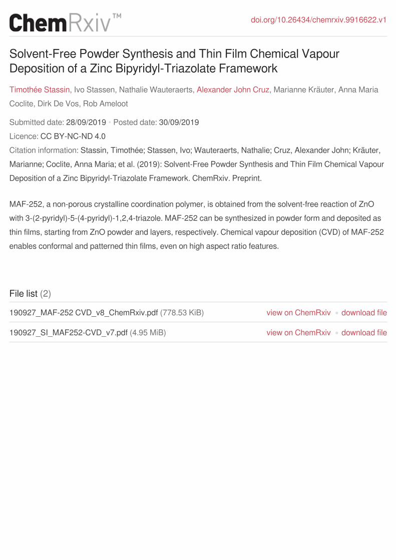
Figure 2. Solvent-free formation of MAF-252 from reaction between ZnO
and 3-(2-pyridyl)-5-(4-pyridyl)-1,2,4-triazolate (Hdpt) vapour. a,
Schematic representation of the powder synthesis. b, Schematic
representation of the film deposition. c, Image of MAF-252 powder and film.
d, Chemical structure of Hdpt and Hmdpt.
S2.1 and S2.2). MAF-252 CVD is a very simple and robust film
deposition process, while ZIF-8 and MAF-6 CVD require precise
control over the atmosphere composition (e.g., relative humidity),
as well as the temperature gradient between substrate and
reactor to achieve reproducible film morphology.[15]
MAF-252 powder and films are crystalline and have similar
ATR-FTIR spectra and diffraction patterns (Figure 2a,d). No
match was found with a known crystal structure. The cell
parameters and symmetry cannot be unambiguously identified
from the powder pattern because of the limited number of
reflections and broad peaks. In both cases, no ZnO is observed
by X-ray diffraction, suggesting complete reaction of ZnO with the
linker, as also reported for MAF-28.[6]
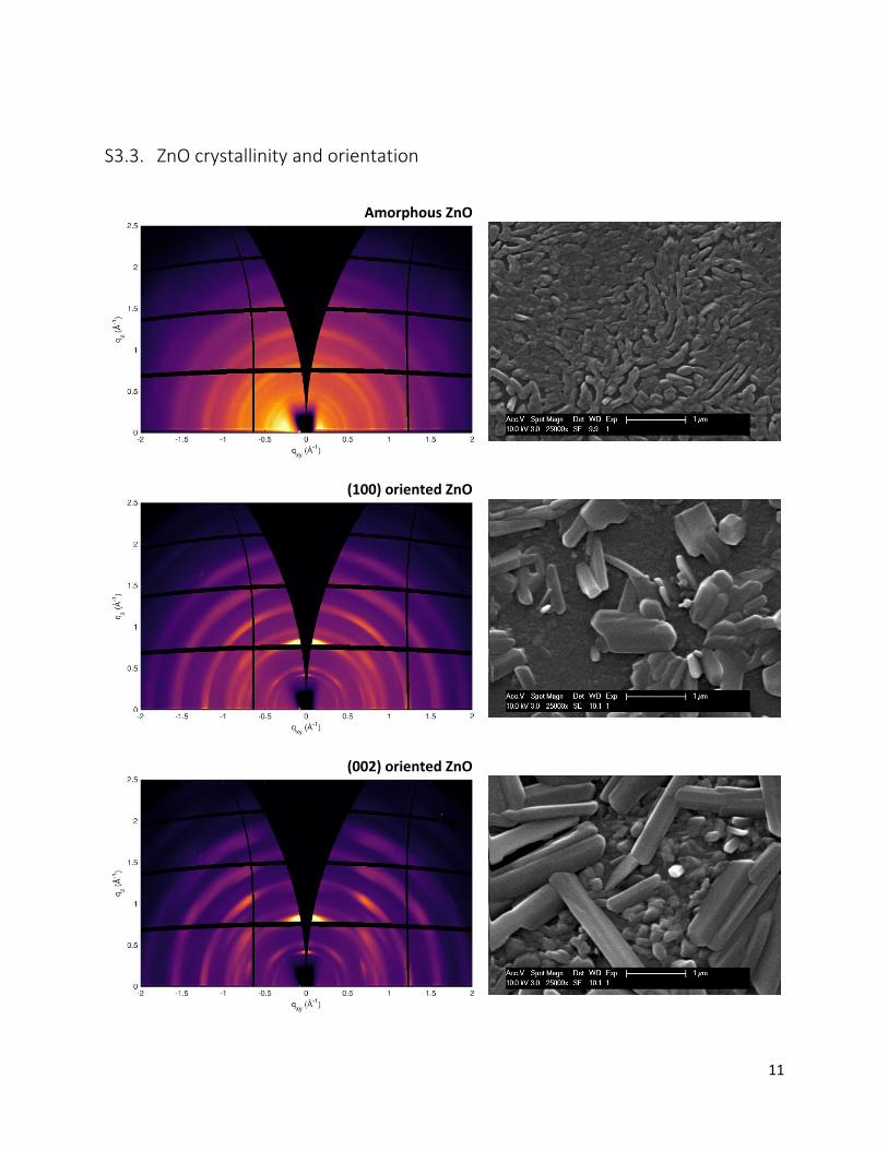
MAF-252 CVD is sensitive to the ZnO crystallinity and
orientation. MAF-252 films grown from amorphous or poorly
crystalline ZnO display a powder-like GIXRD pattern,
characteristic of a random crystallite orientation (Figure S3.5).
Conversely, diffraction spots instead of continuous rings are
observed in the GIXRD pattern of MAF-252 films grown from
(100)-oriented and (002)-oriented crystalline ZnO layers,
suggesting some degree of crystallite orientation (Figure 2e,
Figure S3.5). These observations are reflected in the film
morphology. The morphology of MAF-252 films grown from non-
oriented ZnO and powders as observed by SEM is identical and
consists of elongated micron-sized crystallites, as for MAF-27
([Mg(mdpt)2]) (Figure 2c).[6] Films grown from oriented ZnO
display larger crystallites lying parallel to the surface, that we
believe result in the observed out-of-plane orientation in the
GIXRD patterns. The formation of these large crystallites likely
stems from a difference in MAF-252 nucleation, growth and
crystallite ripening for the different types of ZnO precursor, as
observed elsewhere for ZIF-8 CVD.[15] MAF-252 CVD is
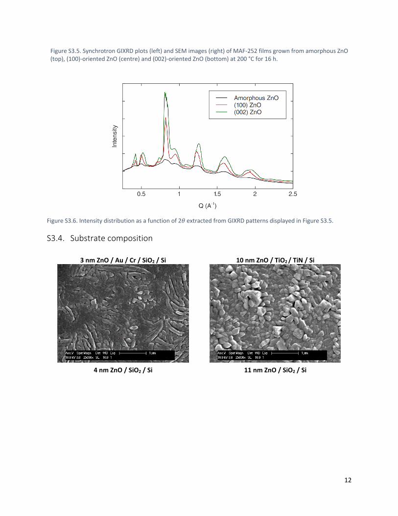
insensitive to the substrate surface chemistry: films with identical
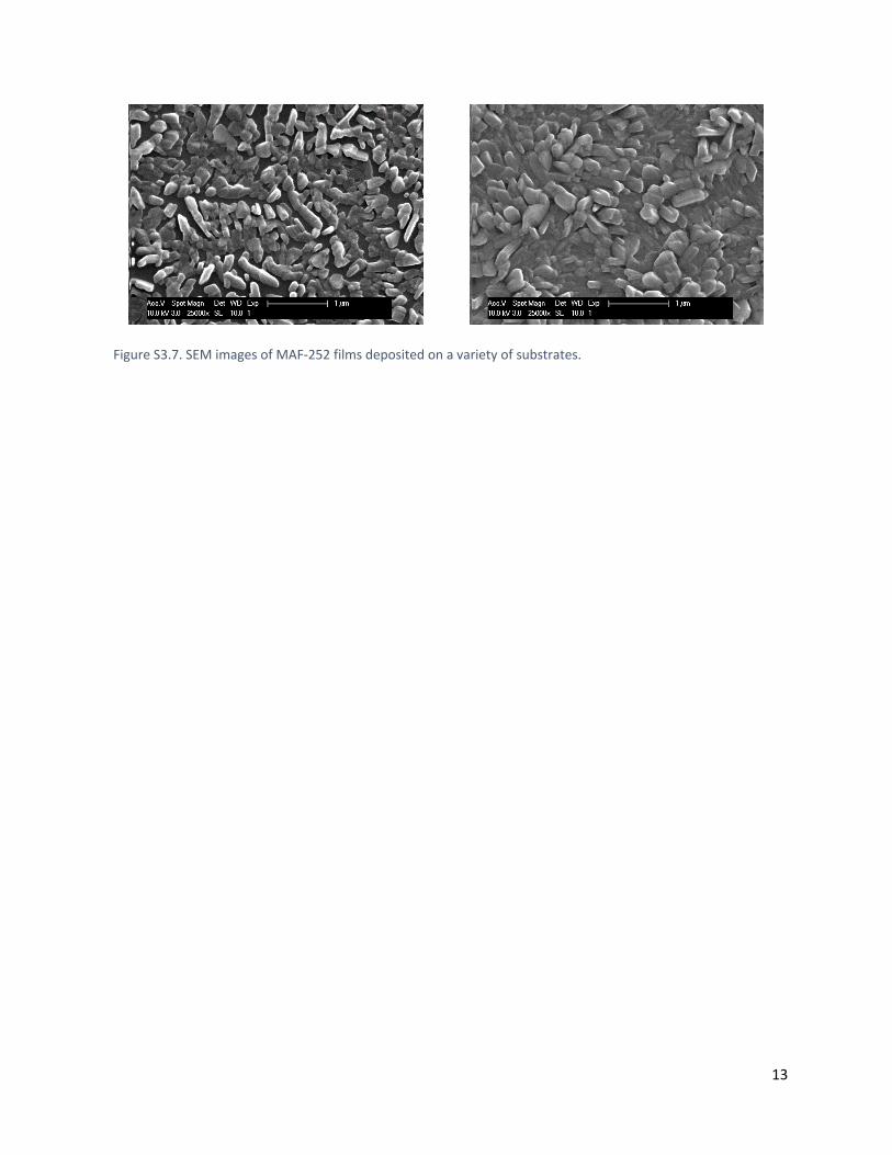
morphology can be deposited on Si, Au, and TiO2 (Figure S3.7).
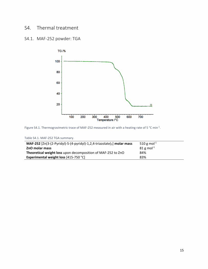
Thermogravimetric analysis of MAF-252 in air shows no
weight loss below 400 °C. (Figure 2b). Above 400 °C, the material
decomposes to ZnO. Since the observed weight loss (83 %)
matches the weight loss expected for [Zn(dpt)2] (84 %), MAF-252
likely has this chemical formula, similar to MAF-25 ([Co(dpt)2])
and MAF-28 ([Zn(mdpt)2]) prepared under the same conditions
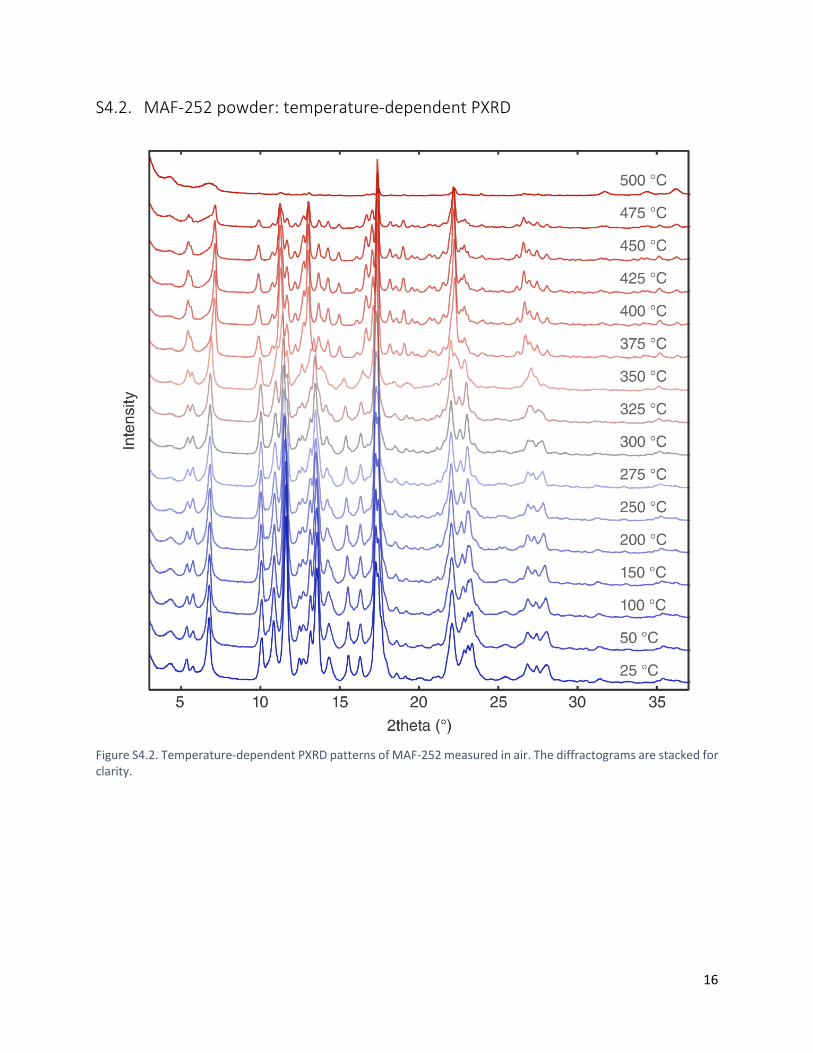
(Table S4.1).[6,7] Temperature-dependent PXRD and SEM
confirm the degradation of MAF-252 above 400 °C (Figures S4.2-
S4.4).
While MAF-25 is porous to both N2 and CO2, no porosity was
detected in MAF-252 powder by N2 and CO2 physisorption, and
in MAF-252 films by Kr physisorption and MeOH ellipsometric
porosimetry, even after activation for 12 h at 350 °C under
dynamic vacuum.
MAF-252 CVD was also investigated as a function of starting
ZnO thickness and CVD reaction time by SEM, GIXRD, AFM, and
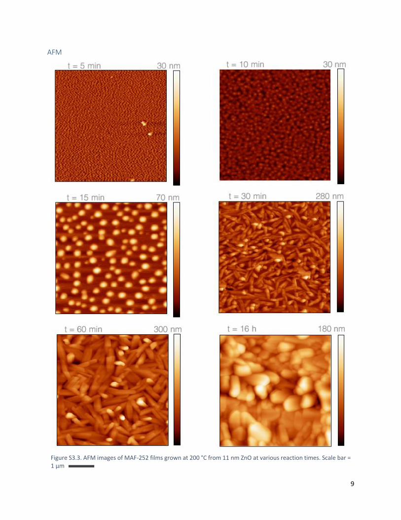
ellipsometry. MAF-252 films grown from 1 nm of ZnO show
scattered crystals on the surface. Thicker ZnO layers yield MAF-
252 films with full surface coverage (Figures S3.2 and S3.3).
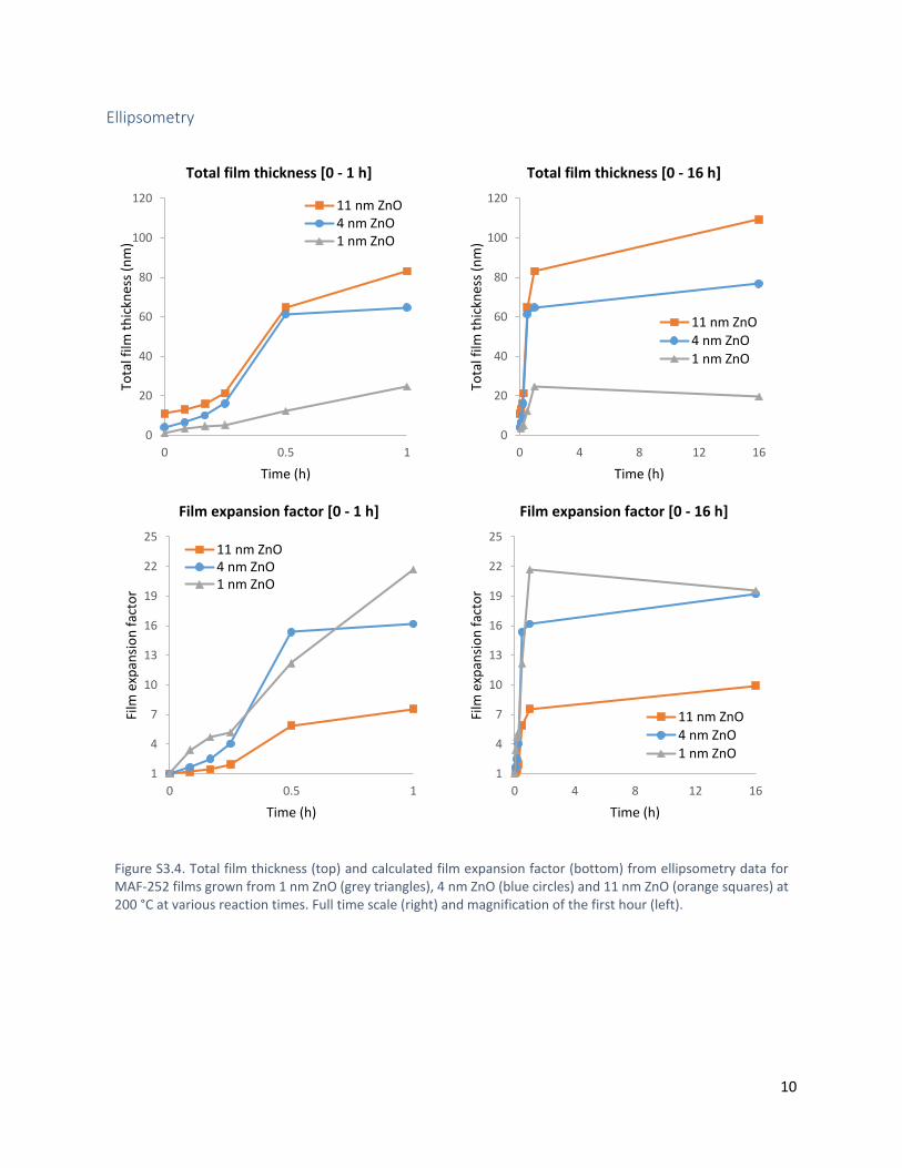
Conversion of ZnO to MAF-252 is paired with a significant
thickness increase. Starting from 1, 4 and 11 nm of ZnO yields
MAF-252 films with a thickness of 19, 77, and 109 nm after 16 h,
respectively (Figure S3.4). The corresponding film thickness
expansion factors are respectively 19, 19 and 10, which is
remarkably large for oxide-to-MAF conversions (Table 1). As
observed for other materials, linker diffusion hindered by the
growing film causes incomplete oxide-to-MAF conversion and a
lower apparent expansion factor (10 vs 19) when starting from
thick oxide layers.[11]
Figure 3. MAF-252 powder and thin films characterisation. a, X-ray diffractogram of MAF-252 powder and film. b, TGA of MAF-252 powder. c, SEM images of
MAF-252 powder, MAF-252 film, and MAF-27 powder reproduced from Ref. 6 with permission from The Royal Society of Chemistry; scale bar = 2 µm. d, ATR-FTIR
spectra of MAF-252 powder and film. e, GIXRD plot of an oriented MAF-252 film grown from (002)-oriented ZnO.
Table 1. MAF structures and corresponding ZnO-to-MAF film expansion
factors.
Material CSD code Density (g cm-3) Film expansion factor[a]
Bulk ZnO ALD ZnO
ZIF-8 (MAF-4) VELVOY 0.95 17 12
MAF-6 MECWOH 0.77 22 15
MAF-28 UYAQER 1.53 24 17
MAF-252 This work - - 19 (exp.)
[a]Theoretical values based on the bulk ZnO density (5.6 g cm-3) and measured
ALD ZnO density (3.9 g cm-3), and the know crystal structure of ZIF-8 (MAF-
4), MAF-6, and MAF-28. Experimental value from the ratio of the measured
ellipsometric film thickness of ZnO precursor and MAF-252 films.
Different growth stages can be observed: smooth and thin
amorphous films in the first 10 min likely corresponding to the
surface reaction between ZnO and Hdpt vapour, followed by
MAF-252 nucleation and crystallization observed as a steep
increase in film thickness and roughness. After 1 h reaction, the
growing MAF-252 film hinders the linker diffusion and further
oxide conversion. At the same time, larger crystallites are formed
by ripening (Figure 3 and S3.4). A similar growth process was
observed for ZIF-8 CVD.[15]
Some applications could benefit from the large film expansion
upon conversion of ZnO to MAF-252 and the high carbon content
of the resulting films (e.g., carbonization for use in
microsupercapacitors). For integration into microelectronics,
compatibility of the deposition process with typical
microfabrication steps is critical. Therefore, the conformality of
MAF-252 CVD and film patterning were evaluated (Figure 4).
Conformal ZnO precursor layers were deposited by atomic layer
deposition (ALD) on high aspect ratio (25:1) silicon micropillars
and converted to conformal MAF-252 films over the whole
micropillar length. ZnO was also patterned on a flat substrate by
lithography and converted to MAF-252. The original pattern was
maintained with high fidelity.
Conclusions
The formation of the non-porous crystalline coordination polymer
MAF-252 from ZnO and a commercially available linker is an
example of the potential of solvent-free, vapour-phase processing.
MAF-252 CVD is compatible with microfabrication. While the
crystal structure of MAF-252 remains to be solved, its integration
in applications could benefit from the robustness and the large
film expansion factor of the deposition process.
Experimental Section
Material and methods can be found in the electronic supporting
information.
Acknowledgments
T.S., N.W. and I.S. thank the Research Foundation Flanders (FWO) for a SB-PhD fellowship (1S53316N and 1SB7919N) and for a postdoctoral fellowship (and 12L5417N). T.S. is grateful to Roland Resel and Sabina Rodríguez-Hermida for fruitful scientific discussions. R.A. acknowledges the funding from the European Research Council (No. 716472, acronym: VAPORE) and the
Figure 5. MAF-252 CVD compatibility with typical microfabrication steps.
a, SEM images of MAF-252 films deposited conformally on high aspect ratio Si
micropillars. b, Schematic representation of MAF-252 CVD on high aspect ratio
micropillars and film patterning. c, SEM images of patterned MAF-252 films;
scale bar = 1 µm.
Figure 4. Time evolution of MAF-252 CVD. a, SEM images, b, thickness by
ellipsometry and RMS roughness by AFM, and c, diffractograms extracted from
GIXRD patterns of MAF-252 films grown from 10 nm ALD ZnO at various
conversion times.
Research Foundation Flanders (FWO) for funding in the research projects G083016N, G0E6319N and 1501618N and the infrastructure project G0H0716N. This study is a result from the lead project Porous Materials @ Work (Graz University of Technology, Austria). We acknowledge the Elettra Synchrotron Trieste for allocation of beamtime and thank Luisa Barba and Nicola Demitri for assistance in using beamline XRD1. Min Tu and Helge Reinsch are acknowledged for optimizing the ZnO patterning protocol and for attempting structure refinement, respectively.
Keywords: coordination polymers • chemical vapour deposition
• thin films • microfabrication • solvent-free reactions
[1] I. M. Hönicke, I. Senkovska, V. Bon, I. A. Baburin, N. Bönisch, S. Raschke, J. D. Evans, S. Kaskel, Angew. Chem. Int. Ed. 2018, 57, 13780–
13783. [2] H. Furukawa, K. E. Cordova, M. O’Keeffe, O. M. Yaghi, Science 2013, 341, 1230444. [3] K. S. Park, Z. Ni, A. P. Cote, J. Y. Choi, R. Huang, F. J. Uribe-Romo, H. K. Chae, M. O’Keeffe, O. M. Yaghi, Proc. Natl. Acad. Sci. 2006, 103, 10186–10191. [4] X.-C. Huang, Y.-Y. Lin, J.-P. Zhang, X.-M. Chen, Angew. Chem. Int. Ed. 2006, 45, 1557–1559.
[5] A.-X. Zhu, R.-B. Lin, X.-L. Qi, Y. Liu, Y.-Y. Lin, J.-P. Zhang, X.-M. Chen, Microporous Mesoporous Mater. 2012, 157, 42–49. [6] J.-B. Lin, R.-B. Lin, X.-N. Cheng, J.-P. Zhang, X.-M. Chen, Chem. Commun. 2011, 47, 9185–9187. [7] J.-B. Lin, J.-P. Zhang, X.-M. Chen, J. Am. Chem. Soc. 2010, 132, 6654–6656. [8] J. López-Cabrelles, J. Romero, G. Abellán, M. Giménez-Marqués, M. Palomino, S. Valencia, F. Rey, G. Mínguez Espallargas, J. Am. Chem. Soc. 2019, 141, 7173–7180. [9] I. Stassen, N. Burtch, A. Talin, P. Falcaro, M. Allendorf, R. Ameloot, Chem. Soc. Rev. 2017, 46, 3185–3241. [10] A. Bétard, R. A. Fischer, Chem. Rev. 2012, 112, 1055–1083. [11] I. Stassen, M. Styles, G. Grenci, H. V. Gorp, W. Vanderlinden, S. D. Feyter, P. Falcaro, D. D. Vos, P. Vereecken, R. Ameloot, Nat. Mater. 2016, 15, 304–310. [12] T. Stassin, S. Rodríguez-Hemida, B. Schrode, A. J. Cruz, F. Carraro, D. Kravchenko, V. Creemers, I. Stassen, T. Hauffman, D. E. D. Vos, et al., Chem. Commun. 2019, 55, 10056–10059. [13] M. Krishtab, I. Stassen, T. Stassin, A. J. Cruz, O. O. Okudur, S. Armini, C. Wilson, S. D. Gendt, R. Ameloot, Nat. Commun. 2019, 10, 1–9. [14] T. Stassin, I. Stassen, J. Marreiros, A. J. Cruz, R. Verbeke, M. Tu, H. Reinsch, M. Dickmann, W. Egger, I. Vankelecom, et al., Solvent-Free Powder Synthesis and MOF-CVD Thin Films of the Mesoporous Metal-Organic Framework MAF-6, 2019. [15] A. J. Cruz, I. Stassen, M. Krishtab, K. Marcoen, T. Stassin, S. Rodríguez-Hermida, J. Teyssandier, S. Pletincx, R. Verbeke, V. Rubio-Giménez, et al., An Integrated Cleanroom Process for the Vapor Phase Deposition of Large-Area Zeolitic Imidazolate Framework Thin Films, 2019.


download fileview on ChemRxiv190927_MAF-252 CVD_v8_ChemRxiv.pdf (778.53 KiB)
Supporting Information
Solvent-free powder synthesis and thin film chemical
vapour deposition of a zinc bipyridyl-triazolate
framework Timothée Stassin,[a] Ivo Stassen,[a] Nathalie Wauteraerts,[a] Alexander John Cruz,[a] Marianne Kräuter,[b]
Anna Maria Coclite,[b] Dirk De Vos,[a] and Rob Ameloot*[a]
[a] Centre for Membrane Separations, Adsorption, Catalysis and Spectroscopy for Sustainable Solutions
(cMACS), KU Leuven, Celestijnenlaan 200F box 2461, 3001 Leuven, Belgium
[b] Institute for Solid State Physics, TU Graz, Petersgasse 16, 8010 Graz, Austria
Correspondence to:
Prof. Dr. Rob Ameloot,
Tel.: +32-1637-6674
Email: [email protected]
2
Contents S1. Methods ............................................................................................................................................ 3
S2. Comparison of Hdpt and HmIm sublimation by TGA ........................................................................ 6
S3. MAF-252 CVD parameter space ........................................................................................................ 7
S3.1. Temperature ................................................................................................................................. 7
S3.2. Time and ZnO thickness ................................................................................................................ 8
S3.3. ZnO crystallinity and orientation ................................................................................................ 11
S3.4. Substrate composition ................................................................................................................ 12
S3.5. Film aging .................................................................................................................................... 14
S4. Thermal treatment .......................................................................................................................... 15
S4.1. MAF-252 powder: TGA ................................................................................................................ 15
S4.2. MAF-252 powder: temperature-dependent PXRD ..................................................................... 16
S4.3. MAF-252 powder: SEM ............................................................................................................... 17
S4.4. MAF-252 films: SEM .................................................................................................................... 18
S5. References ...................................................................................................................................... 19
3
S1. Methods ZnO deposition Amorphous ZnO was deposited by Atomic layer deposition (ALD) on Si substrates with native oxide, and
on gold- or titania-coated Si substrates, using the same conditions and protocol as described by Cruz et
al.1 The amorphous ZnO films have a density of ~3.9 g cm-3 as measured by X-ray reflectivity and
Rutherford backscattering spectroscopy. Crystalline ZnO was deposited by plasma-enhanced ALD as
described by Pilz et al.2 At a substrate temperature of 25 °C and 200 °C, ZnO films with a (100) and (002)
orientation are obtained, respectively.
MAF-252 powder synthesis and thin film CVD
MAF-252 powder synthesis
For the solvent-free synthesis of MAF-252 powder, a powder physical mixture of ZnO nanoparticles (≥
99.5%, 25 nm, Carl Roth ROTI®nanoMETIC, d = 5.6 g cm-3) and 3-(2-Pyridyl)-5-(4-pyridyl)-1,2,4-triazole
(Hdpt, 99%, Alfa Aesar) with 1:2 ratio was heated to 270-300 °C for 16 h in a sealed glass ampoule.
MAF-252 thin film CVD
For the chemical vapour deposition (CVD) of MAF-252 films, substrates coated with 1-15 nm ZnO were
placed in a Schlenk tube together with a glass boat containing Hdpt powder. The tube was closed and
evacuated (~10-1 mbar). In a typical procedure, the tube was then placed for 1 h in a forced convection
oven preheated at 200 °C. For a set of experiments, the temperature of the oven was lowered to 150 and
175 °C, and for another set of experiments, the conversion time was varied between 5 min and 16 h.
Afterward the tube was removed from the oven and vented. The samples were removed from the tube
while hot and left in the oven for 30 additional minutes for activation.
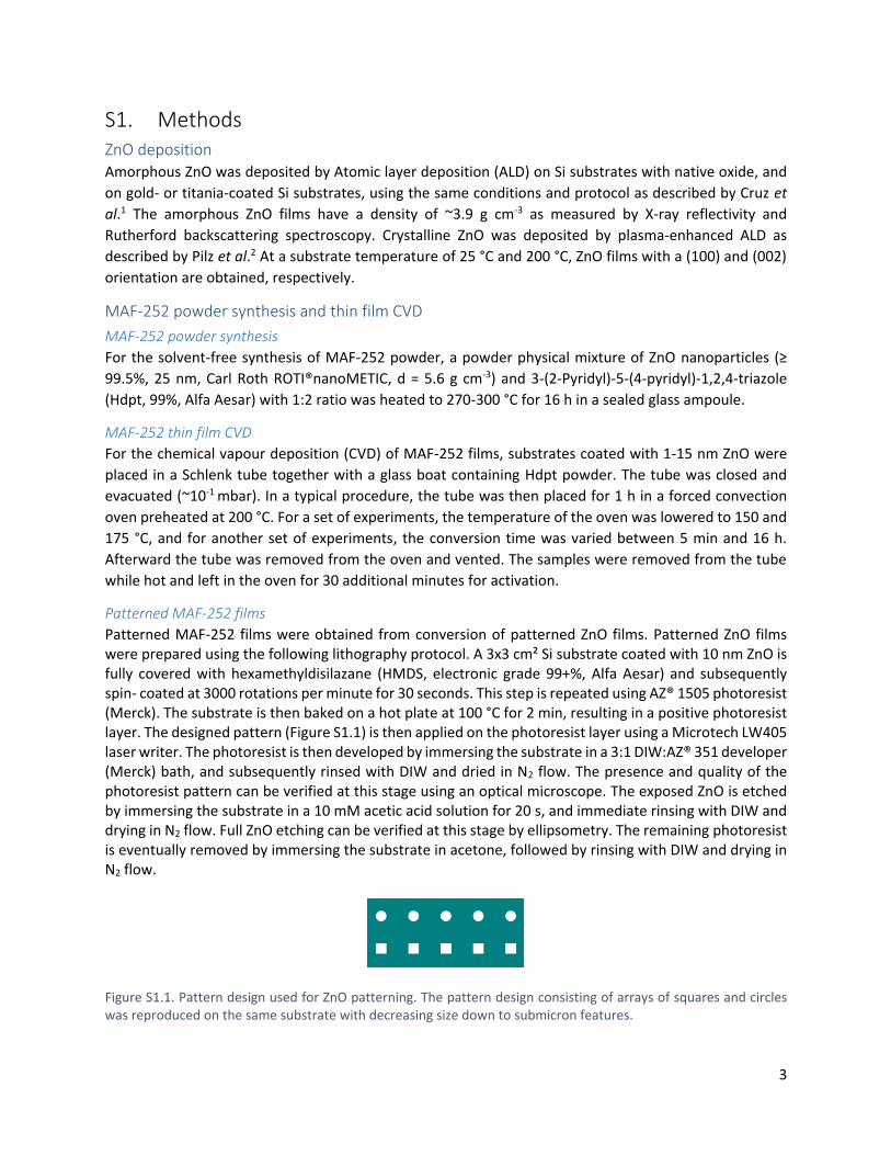
Patterned MAF-252 films
Patterned MAF-252 films were obtained from conversion of patterned ZnO films. Patterned ZnO films were prepared using the following lithography protocol. A 3x3 cm² Si substrate coated with 10 nm ZnO is fully covered with hexamethyldisilazane (HMDS, electronic grade 99+%, Alfa Aesar) and subsequently spin- coated at 3000 rotations per minute for 30 seconds. This step is repeated using AZ® 1505 photoresist (Merck). The substrate is then baked on a hot plate at 100 °C for 2 min, resulting in a positive photoresist layer. The designed pattern (Figure S1.1) is then applied on the photoresist layer using a Microtech LW405 laser writer. The photoresist is then developed by immersing the substrate in a 3:1 DIW:AZ® 351 developer (Merck) bath, and subsequently rinsed with DIW and dried in N2 flow. The presence and quality of the photoresist pattern can be verified at this stage using an optical microscope. The exposed ZnO is etched by immersing the substrate in a 10 mM acetic acid solution for 20 s, and immediate rinsing with DIW and drying in N2 flow. Full ZnO etching can be verified at this stage by ellipsometry. The remaining photoresist is eventually removed by immersing the substrate in acetone, followed by rinsing with DIW and drying in N2 flow.
Figure S1.1. Pattern design used for ZnO patterning. The pattern design consisting of arrays of squares and circles was reproduced on the same substrate with decreasing size down to submicron features.
4
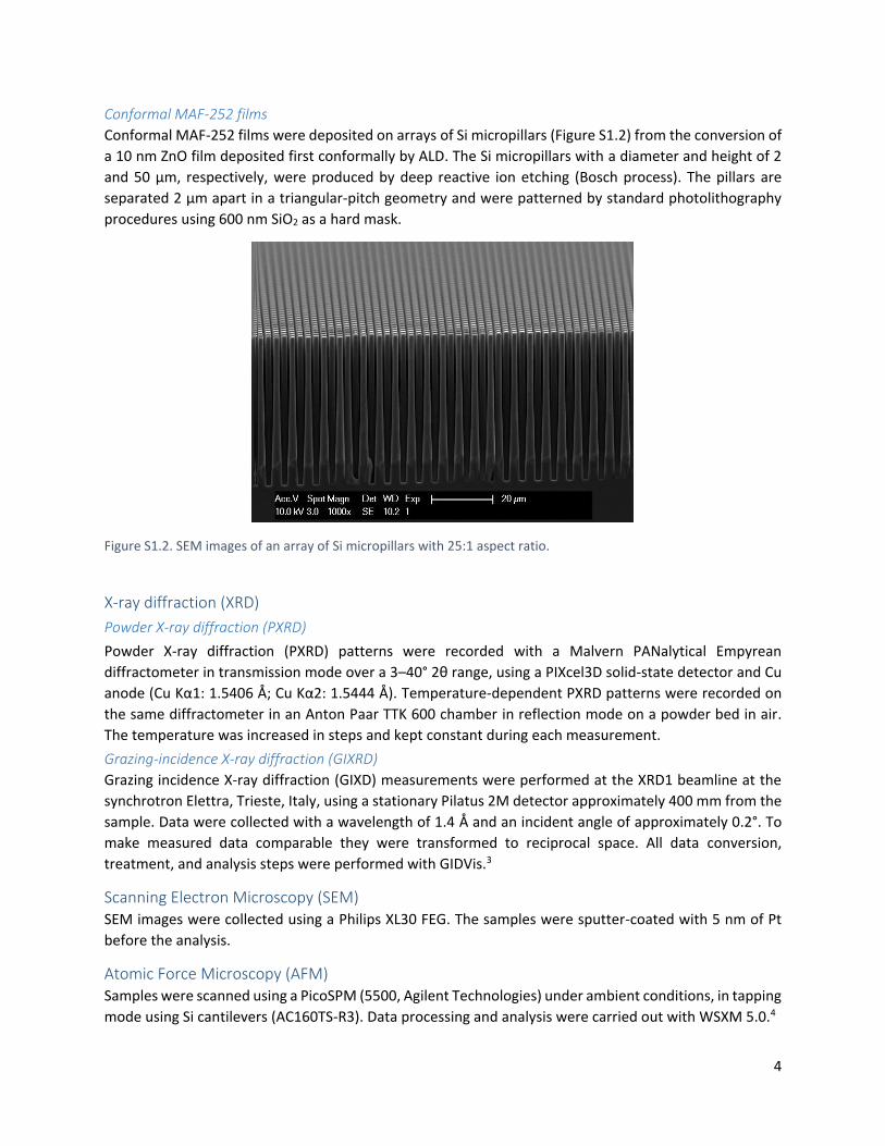
Conformal MAF-252 films
Conformal MAF-252 films were deposited on arrays of Si micropillars (Figure S1.2) from the conversion of
a 10 nm ZnO film deposited first conformally by ALD. The Si micropillars with a diameter and height of 2
and 50 μm, respectively, were produced by deep reactive ion etching (Bosch process). The pillars are
separated 2 μm apart in a triangular-pitch geometry and were patterned by standard photolithography
procedures using 600 nm SiO2 as a hard mask.
Figure S1.2. SEM images of an array of Si micropillars with 25:1 aspect ratio.
X-ray diffraction (XRD)
Powder X-ray diffraction (PXRD)
Powder X-ray diffraction (PXRD) patterns were recorded with a Malvern PANalytical Empyrean
diffractometer in transmission mode over a 3–40° 2θ range, using a PIXcel3D solid-state detector and Cu
anode (Cu Kα1: 1.5406 Å; Cu Kα2: 1.5444 Å). Temperature-dependent PXRD patterns were recorded on
the same diffractometer in an Anton Paar TTK 600 chamber in reflection mode on a powder bed in air.
The temperature was increased in steps and kept constant during each measurement.
Grazing-incidence X-ray diffraction (GIXRD)
Grazing incidence X-ray diffraction (GIXD) measurements were performed at the XRD1 beamline at the
synchrotron Elettra, Trieste, Italy, using a stationary Pilatus 2M detector approximately 400 mm from the
sample. Data were collected with a wavelength of 1.4 Å and an incident angle of approximately 0.2°. To
make measured data comparable they were transformed to reciprocal space. All data conversion,
treatment, and analysis steps were performed with GIDVis.3
Scanning Electron Microscopy (SEM) SEM images were collected using a Philips XL30 FEG. The samples were sputter-coated with 5 nm of Pt
before the analysis.
Atomic Force Microscopy (AFM) Samples were scanned using a PicoSPM (5500, Agilent Technologies) under ambient conditions, in tapping
mode using Si cantilevers (AC160TS-R3). Data processing and analysis were carried out with WSXM 5.0.4
5
Attenuated Total Reflectance Fourier Transform Infrared Spectroscopy (ATR-FTIR) Infrared spectra were recorded (64 scans, 4 cm-1 resolution) over the spectral range 400-4000 cm-1 on a
Varian 670 FTIR spectrometer attached to a Varian 620 FTIR microscope equipped with a slide-on Ge ATR
tip. For FTIR measurements, MAF-252 films were deposited on gold-coated Si substrates.
Ellipsometry Optical properties of the deposited layers were measured using an M-2000x spectroscopic ellipsometer
(J. A. Woollam Co. Inc., λ = 246-1000 nm) and using a Cauchy model.
Thermogravimetry (TG) Thermogravimetric analysis was carried out in air using a Netzsch STA 449 F3 Jupiter thermogravimetric
analyser at a heating rate of 5 °C min-1. For the linker sublimation thermogravimetric measurements, a
TGA Q500 station from TA instruments operating under nitrogen atmosphere was used.
Porosimetry Kr sorption was performed at -196 °C on a MAF-252 film deposited on silicon micropillars using a
Micromeritics 3Flex 3500 instrument performed as described in our previous work.5 Methanol
ellipsometric porosimetry was performed on a blanket MAF-252 film placed inside a custom porosimetry
chamber equipped with an ellipsometer (Sentech SE801, λ = 350-850 nm) and a programmable adsorbate
dosing platform. Data were recorded at room temperature, with an equilibration time of 30 s for each
data point. N2 and CO2 sorption were performed at -196°C and 0 °C, respectively, on MAF-252 powder
activated for 12 h under dynamic vacuum at 300°C and 350 °C, respectively, using a Micromeritics 3Flex
3500 instrument.
6
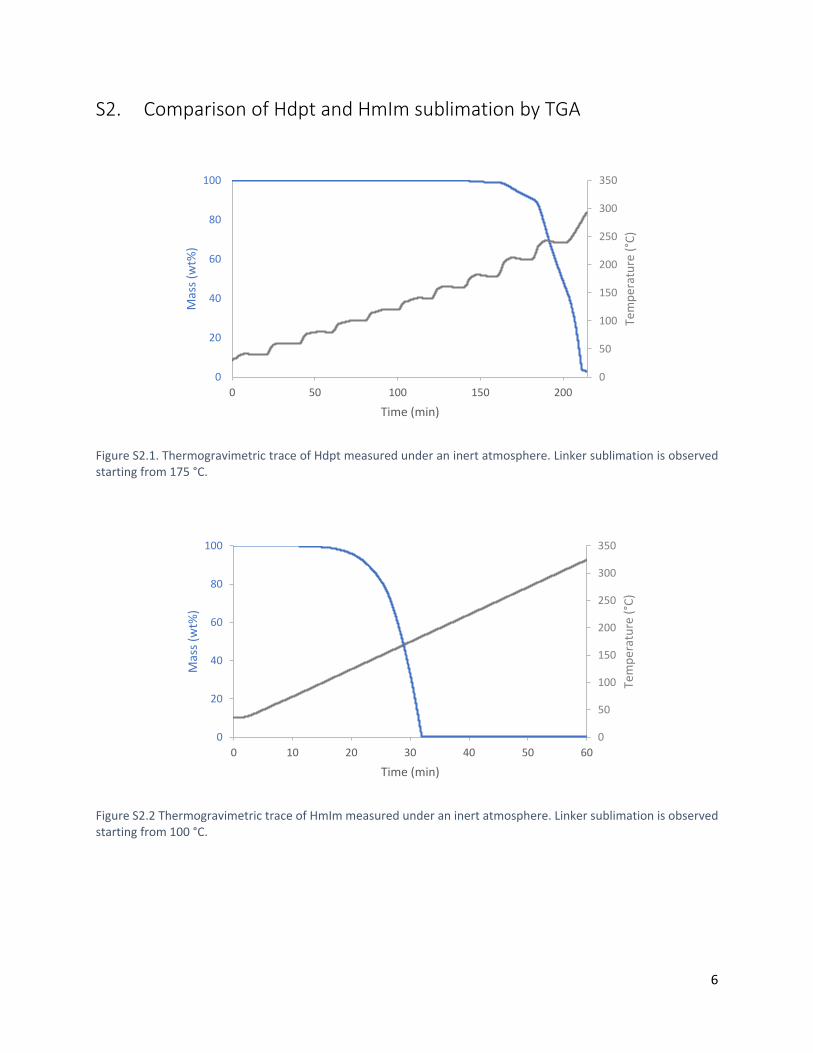
S2. Comparison of Hdpt and HmIm sublimation by TGA
Figure S2.1. Thermogravimetric trace of Hdpt measured under an inert atmosphere. Linker sublimation is observed starting from 175 °C.
Figure S2.2 Thermogravimetric trace of HmIm measured under an inert atmosphere. Linker sublimation is observed starting from 100 °C.
0
50
100
150
200
250
300
350
0
20
40
60
80
100
0 50 100 150 200
Tem
per
atu
re (
°C)
Mas
s (w
t%)
Time (min)
0
20
40
60
80
100
0 10 20 30 40 50 60
0
50
100
150
200
250
300
350
Mas
s (w
t%)
Time (min)
Tem
per
atu
re (
°C)
7
S3. MAF-252 CVD parameter space
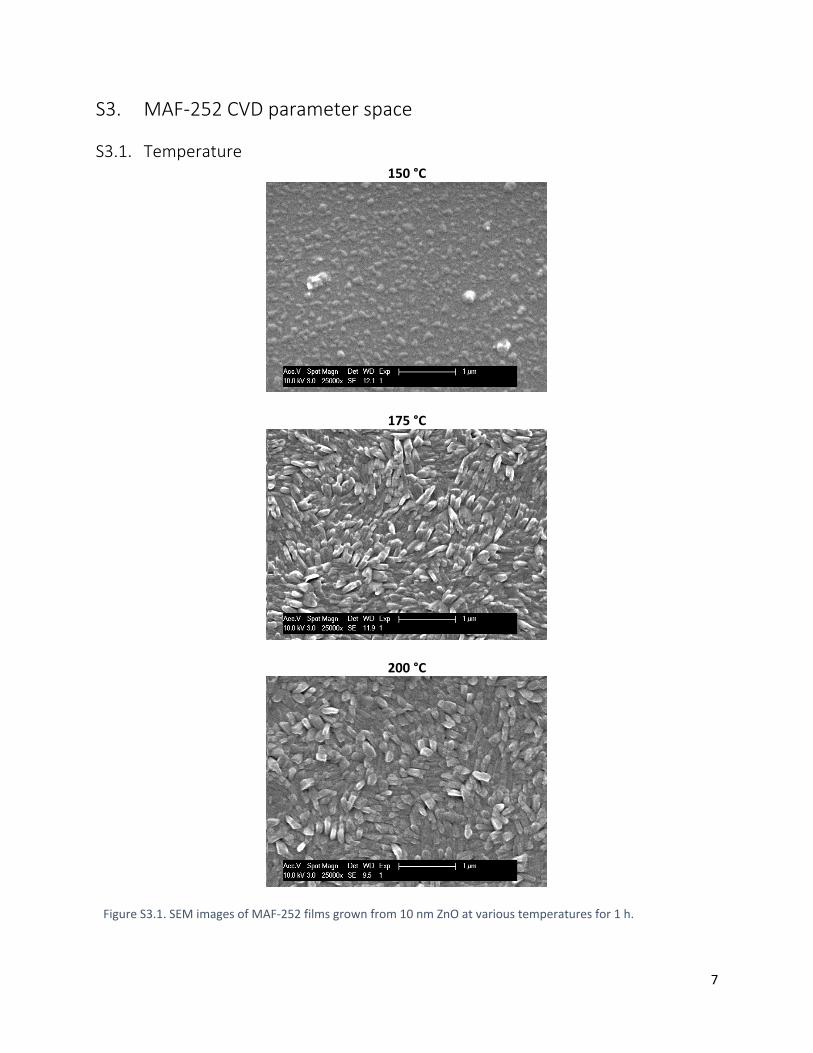
S3.1. Temperature 150 °C
175 °C
200 °C
Figure S3.1. SEM images of MAF-252 films grown from 10 nm ZnO at various temperatures for 1 h.

8
S3.2. Time and ZnO thickness
SEM 1 nm ZnO 4 nm ZnO 11 nm ZnO
5 min
10 min
15 min
30 min
60 min
16 h
Figure S3.2. SEM images of MAF-252 films grown at 200 °C from increasing ZnO thicknesses and reaction times.
Scale bar = 1 µm
9
AFM
Figure S3.3. AFM images of MAF-252 films grown at 200 °C from 11 nm ZnO at various reaction times. Scale bar = 1 µm
10
Ellipsometry
Total film thickness [0 - 1 h]
Total film thickness [0 - 16 h]
Film expansion factor [0 - 1 h]
Film expansion factor [0 - 16 h]
Figure S3.4. Total film thickness (top) and calculated film expansion factor (bottom) from ellipsometry data for MAF-252 films grown from 1 nm ZnO (grey triangles), 4 nm ZnO (blue circles) and 11 nm ZnO (orange squares) at 200 °C at various reaction times. Full time scale (right) and magnification of the first hour (left).
0
20
40
60
80
100
120
0 0.5 1
Tota
l film
th
ickn
ess
(nm
)
Time (h)
11 nm ZnO4 nm ZnO1 nm ZnO
0
20
40
60
80
100
120
0 4 8 12 16
Tota
l film
th
ickn
ess
(nm
)Time (h)
11 nm ZnO4 nm ZnO1 nm ZnO
1
4
7
10
13
16
19
22
25
0 0.5 1
Film
exp
ansi
on
fac
tor
Time (h)
11 nm ZnO4 nm ZnO1 nm ZnO
1
4
7
10
13
16
19
22
25
0 4 8 12 16
Film
exp
ansi
on
fac
tor
Time (h)
11 nm ZnO4 nm ZnO1 nm ZnO
11
S3.3. ZnO crystallinity and orientation
Amorphous ZnO
(100) oriented ZnO
(002) oriented ZnO
12
Figure S3.5. Synchrotron GIXRD plots (left) and SEM images (right) of MAF-252 films grown from amorphous ZnO (top), (100)-oriented ZnO (centre) and (002)-oriented ZnO (bottom) at 200 °C for 16 h.
Figure S3.6. Intensity distribution as a function of 2𝜃 extracted from GIXRD patterns displayed in Figure S3.5.
S3.4. Substrate composition
3 nm ZnO / Au / Cr / SiO2 / Si
10 nm ZnO / TiO2 / TiN / Si
4 nm ZnO / SiO2 / Si 11 nm ZnO / SiO2 / Si
13
Figure S3.7. SEM images of MAF-252 films deposited on a variety of substrates.
14
S3.5. Film aging
Fresh
3 months of aging
15 min
30 min
60 min
16 h
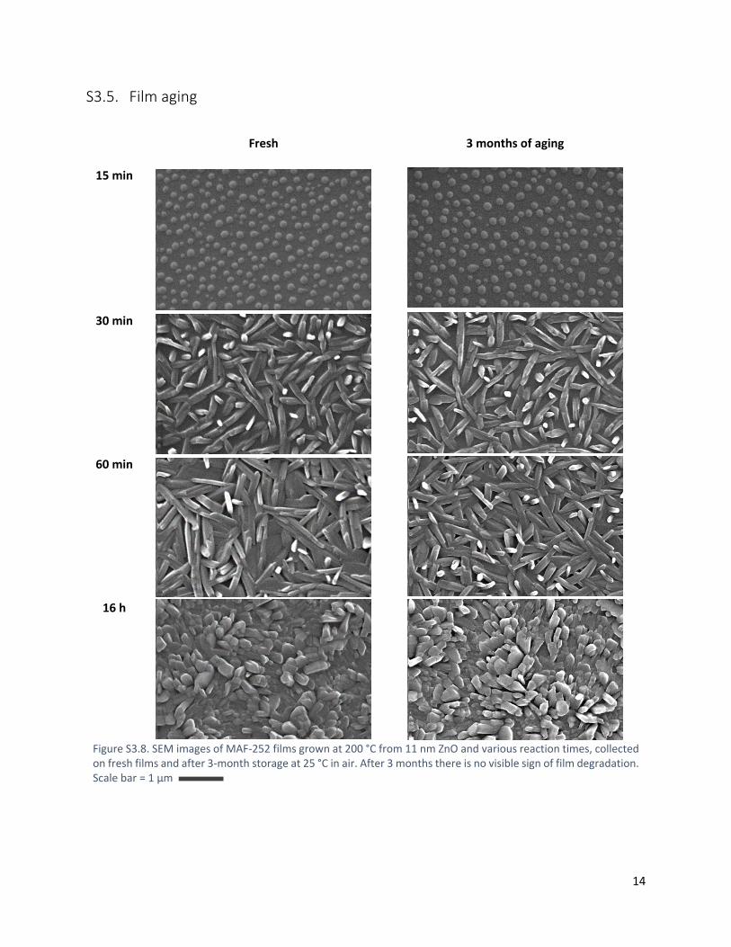
Figure S3.8. SEM images of MAF-252 films grown at 200 °C from 11 nm ZnO and various reaction times, collected on fresh films and after 3-month storage at 25 °C in air. After 3 months there is no visible sign of film degradation. Scale bar = 1 µm
15
S4. Thermal treatment
S4.1. MAF-252 powder: TGA
Figure S4.1. Thermogravimetric trace of MAF-252 measured in air with a heating rate of 5 °C min-1.
Table S4.1. MAF-252 TGA summary.
MAF-252 [Zn(3-(2-Pyridyl)-5-(4-pyridyl)-1,2,4-triazolate)2] molar mass 510 g mol-1 ZnO molar mass 81 g mol-1 Theoretical weight loss upon decomposition of MAF-252 to ZnO 84% Experimental weight loss [415-750 °C] 83%
16
S4.2. MAF-252 powder: temperature-dependent PXRD
Figure S4.2. Temperature-dependent PXRD patterns of MAF-252 measured in air. The diffractograms are stacked for clarity.
17
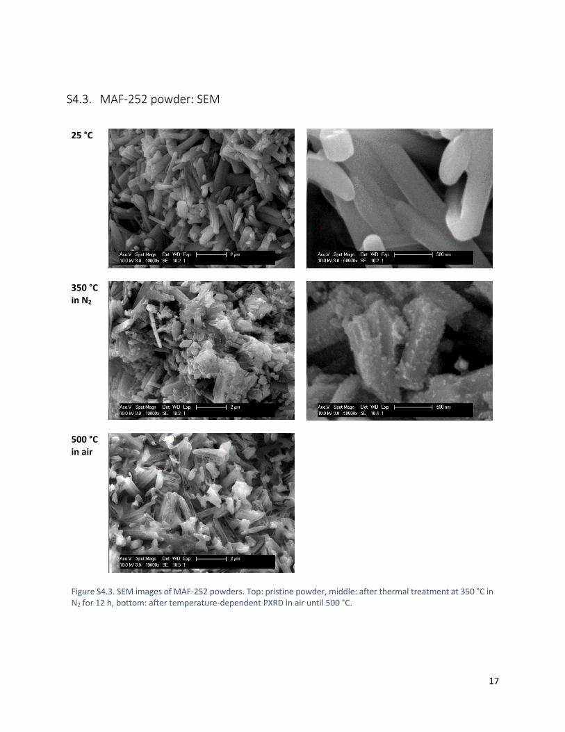
S4.3. MAF-252 powder: SEM
25 °C
350 °C in N2
500 °C in air
Figure S4.3. SEM images of MAF-252 powders. Top: pristine powder, middle: after thermal treatment at 350 °C in N2 for 12 h, bottom: after temperature-dependent PXRD in air until 500 °C.
18
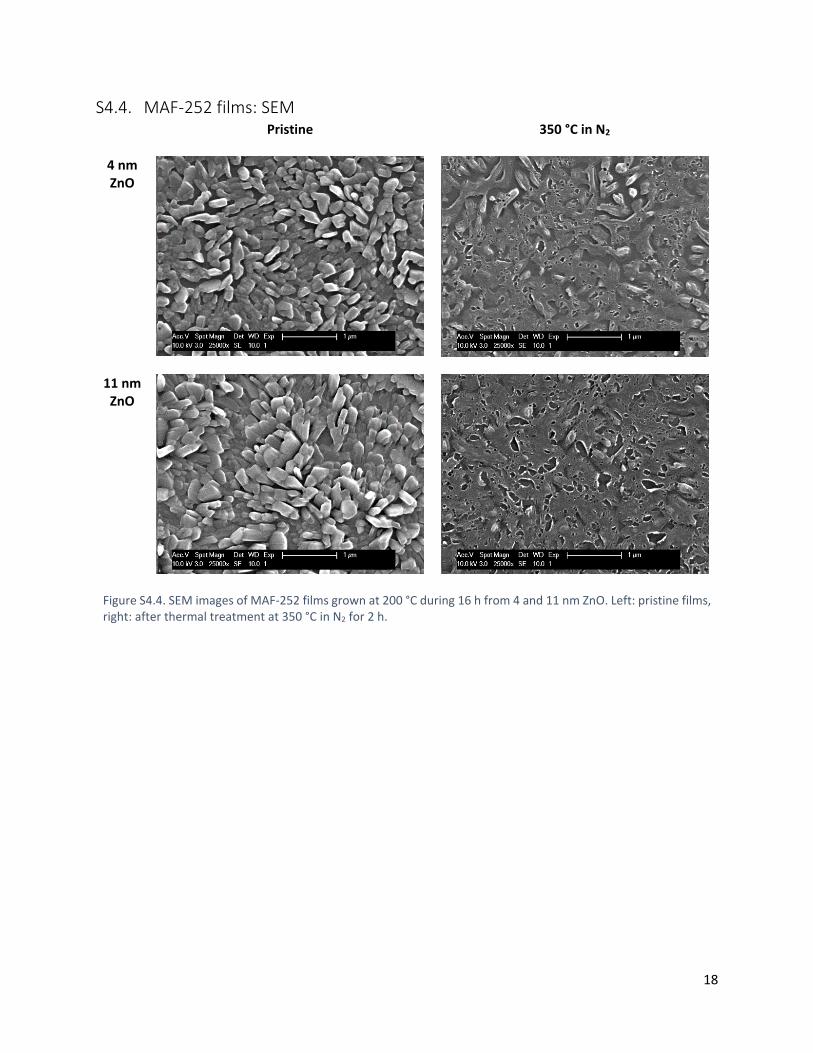
S4.4. MAF-252 films: SEM Pristine
350 °C in N2
4 nm ZnO
11 nm ZnO
Figure S4.4. SEM images of MAF-252 films grown at 200 °C during 16 h from 4 and 11 nm ZnO. Left: pristine films, right: after thermal treatment at 350 °C in N2 for 2 h.
19
S5. References
1 A. J. Cruz, I. Stassen, M. Krishtab, K. Marcoen, T. Stassin, S. Rodríguez-Hermida, J. Teyssandier, S. Pletincx, R. Verbeke, V. Rubio-Giménez, S. Tatay, C. Martí-Gastaldo, J. Meersschaut, P. Vereecken, S. De Feyter, T. Hauffman and R. Ameloot, An Integrated Cleanroom Process for the Vapor Phase Deposition of Large-Area Zeolitic Imidazolate Framework Thin Films, 2019.
2 J. Pilz, A. Perrotta, G. Leising and A. M. Coclite, Phys. Status Solidi A, 0, 1900256. 3 B. Schrode, S. Pachmajer, M. Dohr, C. Röthel, J. Domke, T. Fritz, R. Resel and O. Werzer, J. Appl.
Crystallogr., 2019, 52, 683–689. 4 I. Horcas, R. Fernández, J. M. Gómez-Rodríguez, J. Colchero, J. Gómez-Herrero and A. M. Baro, Rev. Sci.
Instrum., 2007, 78, 013705. 5 I. Stassen, M. Styles, G. Grenci, H. V. Gorp, W. Vanderlinden, S. D. Feyter, P. Falcaro, D. D. Vos, P.
Vereecken and R. Ameloot, Nat. Mater., 2016, 15, 304–310.

download fileview on ChemRxiv190927_SI_MAF252-CVD_v7.pdf (4.95 MiB)


