

AMB Oberlungwitz GmbH – Obere Hauptstraße 20 – D-09228 Chemnitz (OT-Wittgensdorf)
PRODUKTKATALOG 2020
Seilrollen, Treibscheiben und Zubehör
für Neuanlagen, Modernisierungen und als Ersatzteile für Bestandsanlagen
Stand 01.10.2020
Produktkatalog Seil- und
Treibscheiben für Aufzüge nach Maß
I Hinweise und Lieferbedingungen / Details and Terms of Delivery
II Wälzlagerseilrollen, normale Belastung, Standardprogramm Typ “W“ ab Seite
Ø 160 bis 240mm für Rillenabstand 6 bis 10mm ................................................................... 1
Ø 330 bis 410mm für Rillenabstand 14 bis 18mm ................................................................. 2
Ø 450 bis 660mm für Rillenabstand 16 bis 18mm ................................................................. 3
Ø 160 bis 240mm für Rillenabstand 11 bis 14mm ................................................................. 6
Ø 330 bis 660mm für Rillenabstand 19 bis 21mm ................................................................. 7
III Wälzlagerseilrollen, erhöhte Belastung Standardprogramm Typ “WE“
Ø 160 bis 240mm für Rillenabstand 6 bis 10mm ................................................................. 11
Ø 330 bis 410mm für Rillenabstand 14 bis 18mm ............................................................... 12
Ø 450 bis 810mm für Rillenabstand 16 bis 25mm ............................................................... 13
Ø 160 bis 240mm für Rillenabstand 11 bis 14mm ............................................................... 17
Ø 330 bis 560mm für Rillenabstand 19 bis 21mm ............................................................... 18
Ø 610 bis 810mm für Rillenabstand 19 bis 32mm ............................................................... 21
IV Wälzlagerseilrollen, erhöhte Belastung Sondertypen Typ “WES“
Ø 240 bis 520mm für Rillenabstand 10 bis 22mm ............................................................... 23
Ø 560 bis 650mm für Rillenabstand 14 bis 18mm ............................................................... 24
V Übersicht zur allgemeinen Einordnung lieferbarer Seilrollenabmessungen ................ 25
VI Anhang – Datenblätter und Maßskizzen für Anfragen/ Bestellungen
Achshalterausführung .............................................................................................................
Lagerbockausführung .............................................................................................................
Sonderausführung ..................................................................................................................
Gleitlagerausführung...............................................................................................................
Treibscheibe, einteilig .............................................................................................................
Treibscheibe, einteilig, kegelige Bohrung ................................................................................
Treibscheibenkranz ................................................................................................................
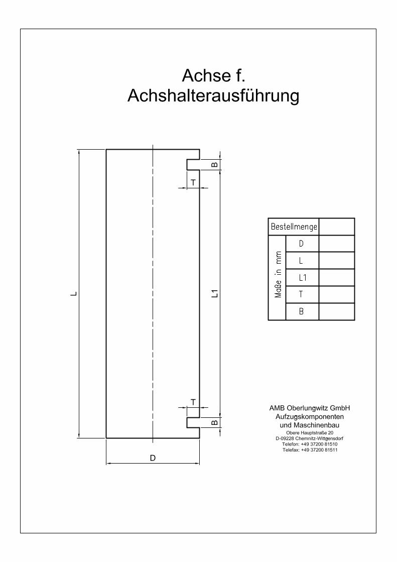
Achse für Achshalterausführung .............................................................................................

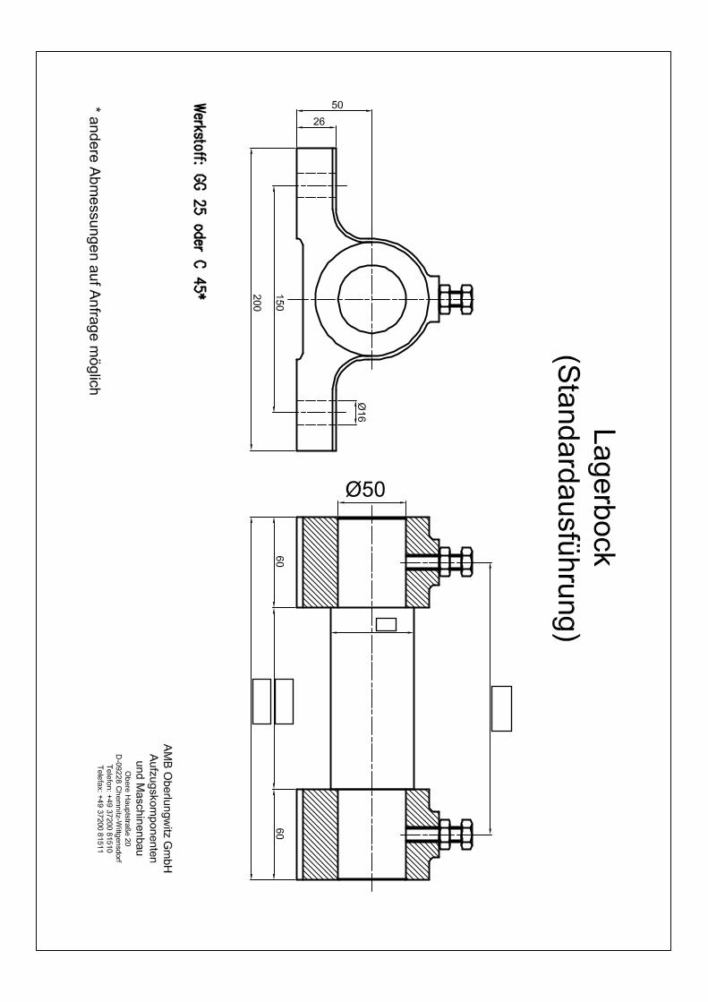
Achse mit Lagerbock für Lagerbockausführung ......................................................................
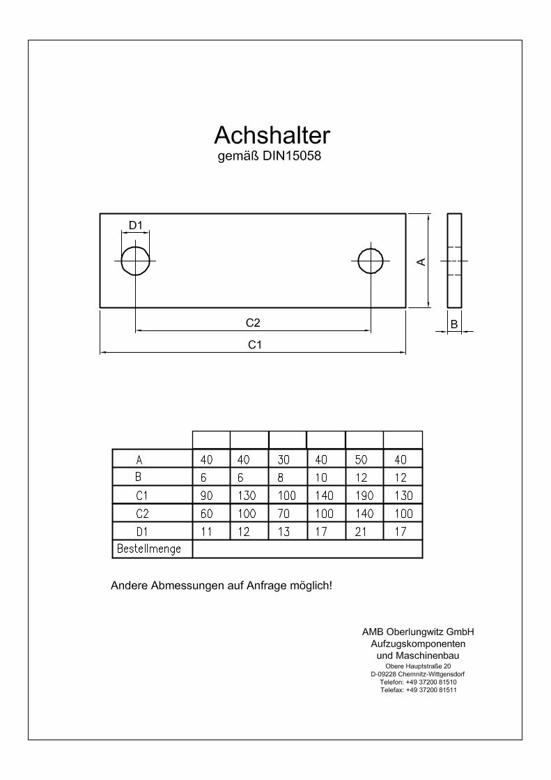
Achshalter für Achshalterausführung ......................................................................................
Distanzring für Achshalter und Lagerbockausführung .............................................................
Treibscheibenklemme .............................................................................................................
Anleitung/ Hilfestellung für Aufmaß Seilrolle – Vorgehensweise .............................................
VII Antwort-Fax .............................................................................................................
VIII Anfahrt Skizze ....................................................................................................................

Hinweise und Lieferbedingungen Bezeichnung der Seilrollen und Treibscheiben Bei Anfragen und Bestellungen bitten wir Sie, unsere Bezeichnung zu verwenden. Zum
besseren Verständnis sei dies nachfolgend einmal erklärt. Bitte beachten Sie, dass in unseren
Maßblättern ebenfalls auf diese Bezeichnung zurückgegriffen wird.
WES 334 – 18 – X
Lagerbezeichnung (z.B. 6211-2Z o. 22212) oder Bohrung bei
Treibscheiben bzw. Gleitlagerseilrollen
Rillenabstand (von Mitte Rille zu Mitte Rille)
Anzahl der Seile
Wirkdurchmesser x 10mm
Artikel W Wälzlager
WE Wälzlagerseilrolle, erhöhte Belastung
WES Wälzlagerseilrolle, erhöhte Belastung - Sondertyp
G Gleitlagerseilrolle
TR Treibscheibe, einteilig
TRK Treibscheibenkranz
Sollten Sie einmal eine Seilrolle nicht in unserem Katalog finden, können wir Ihnen im
Rahmen einer Anfrage mittels unserer Anfrageformulare im Anhang ganz bestimmt
weiterhelfen.
Werkstoffe Unsere Produkte werden aus qualitativ hochwertigen Werkstoffen gefertigt.
Für unsere Seilrollen verwenden wir GG25 mit einer Härte von 210-240 HB. Diese
Gussrohlinge beziehen wir ausschließlich von deutschen Gießereien.
Die Achsen werden aus C 45 gefertigt. Die Mindestzugfestigkeit liegt bei Rm = 550 N/mm2.
(zum Vergleich dazu hat St 52-3 eine Mindestzugfestigkeit von Rm =510 N/mm2) Lagerböcke
können sowohl in Gussausführung für stehende Montage als auch in Stahl für hängende
Montage angeboten werden.
Wälzlager Die in unseren Produkten Verwendung findenden Wälzlager werden uns von der Firma ZKL
geliefert. Auf Wunsch und gegen Aufpreis komplettieren wir unsere Seilrollen auch mit Lagern
anderer Hersteller.
Alle Rillenkugellager werden lebensdauergeschmiert in der Ausführung 2Z oder 2RS (mit
Deckscheiben) eingebaut.
Für besondere Einsatzfälle ist die Verwendung von Schrägkugel-, Zylinderrollen- und
Pendelrollenlagern möglich.

Toleranzen Unsere Produkte werden, sofern nichts anderes angegeben ist, mit den Allgemeintoleranzen
nach ISO 2897 — mittel — gefertigt.
Unsere Achsen werden zum Zweck einer verbesserten Montagefreundlichkeit mit der
Passung f8 hergestellt.
Bemessung und Lebensdauer Bei der Bemessung einer Seilrolle sind die nachfolgend aufgeführten Punkte zu beachten. Die
Rollenbelastung (Achslast) setzt sich aus verschiedenen Arten der Belastung zusammen.
1. Statische Last
Die auf eine Seilrolle wirkende statische Belastung lässt sich mit nachfolgender Formel
sehr einfach berechnen.
F = 2 x Fs x sin (αu/2) Fs - Seillast [kg]
αu - Umschlingungswinkel
Unter der Seillast versteht man entweder die Summe die sich aus der Masse der Kabine
und der Nutzlast ergibt oder die Masse des Gegengewichtes.
2. Dynamische Last
Bei der dynamischen Beanspruchung ist die durch die Einbringung von Schwingungen
zusätzlich hinzukommende Last zu berücksichtigen. Im Allgemeinen sollte versucht
werden Schwingungen in Aufzügen soweit zu reduzieren, dass diese nicht mehr
wahrnehmbar sind und die Belastung im Aufzug nicht vergrößern. Sollte die Berechnung
dieser zusätzlichen Schwingungsbelastungen nicht möglich sein, ist eine Verringerung
der im Katalog genannten Tragfähigkeit der Seilrolle um 40 % vorzunehmen.
3. Stoßbelastungen
Im Aufzug auftretende zusätzliche Stoßbelastungen, welche natürlich auch auf die
Seilrollen wirken, müssen zusätzlich zur statischen Belastung bei der Bemessung
Beachtung finden.
Achsberechnungen sind durch den Aufzugskonstrukteur vorzunehmen. Hierbei ist zu
beachten, dass die Einspannlänge der Achse (Abstand zwischen Stegblech und Lagermitte)
so kurz wie möglich gehalten wird.
Die Lebensdauer unserer Wälzlager ist entsprechend der Angaben der Wälzlagerhersteller
auf eine Betriebsstundenzeit von 8000 Stunden ausgelegt. Sollte eine andere
Betriebsstundenzahl erforderlich sein, so ist dies gesondert anzugeben. Zudem wurde eine
Geschwindigkeit von 0,63 m/s angenommen.
Lieferumfang Alle Seilrollen werden standardmäßig ohne Zubehör ausgeliefert.
Seilrollenzubehör, wie Achsen, Achshalter, Lagerböcke und Distanzringe sind gesondert zu
bestellen und werden nach Kundenwunsch angefertigt.
Die Seilrollen bzw. Treibscheiben sind in Verkehrsgelb bleifrei grundiert und werden
standardmäßig komplett bzw. auf Sonderwunsch mit metallisch blanken Seilrillen geliefert.
Hinweis/ Tipp der Firma AMB GmbH ! Anleitung für die Ermittlung der Maße einer Seilrolle in Bestandsanlagen im Blick auf
einen Austausch bzw. Modernisierung.
Siehe dazu Grafik auf letzter Seite des Anhang von diesem Katalog oder auf der Website (www.amb-seilrollen.de), welche im Bedarfsfall dem Monteur als Hilfsmittel/ Anleitung zur Verfügung steht, damit im Fall einer Ersatzteilanfrage keine notwendigen Daten fehlen!

Details and Terms of Delivery
Designation of the deflection pulleys and traction sheaves
For any inquiries and orders, please be so kind as to use our designation. In the following, we
will explain this designation in order to make it more clear to you. Please pay attention to the
fact that these designations are also used on our dimensioned drawings.
WES 334 – 18 – X
bearing Code (for example 6211-2Z or 22212) or bore in traction
sheaves or deflection pulley with sleeve bearings
Distance of the grooves (middle groove to middle groove)
Number of ropes
Effective diameter x 10mm
Kind of pulley W deflection pulley with roller bearings
WE deflection pulley with roller bearings
WES deflection pulley with roller bearings - special version
G deflection pulley with sleeve bearings
TR traction sheave, one-piece
TRK traction sheave (screw connection)
If it happens that you do not find the rope pulley you need in our catalogue, we will certainly
be able to help you within the framework of a special product manufactured according to your
specifications.
Materials
Our products are made of high-grade materials.
For our rope pulleys, we use GG25 having a minimum hardness of 220HB. We buy our
castings exclusively from German foundries.
Our axles are made of C35. The minimum tensile strength amounts to Rm = 550 N/mm².
(In comparison with that, St 52-3 has a minimum tensile strength of Rm = 510 N/mm².)
We can offer bearing blocks both as castings for the assembly as upright components and as
products made of steel for the assembly as hanging components.
Roller bearings
The rolling bearings (meeting the standard DIN 625) that are used in our products are
supplied by the company ZKL. On request and for an extra charge, we also complete our rope
pulleys with bearings of FAG or SKF.
All deep-groove ball bearings are mounted with lifetime lubrication in the version -2Z (with
cover disks).
For particular cases of application, it is possible to use two-row angular ball bearings and
cylindrical roller bearings.
Tolerances
Unless otherwise specified, our products are manufactured meeting the general tolerances
according to ISO 2897 - medium.
The maximum radial and axial run-outs of the rope pulleys amount to 0.2 mm.
In order to facilitate their assembly, our axles are manufactured with the fit f8.
Dimensioning and service life
The following aspects must be taken into account for the dimensioning of a rope pulley.
The pulley load (axle load) is composed of various kinds of load.
1. Static load
The static load acting on a rope pulley can be very easily calculated by means of the
following formula:
F = 2 x Fs x sin (au/2)Fs - rope load (kgs)
au - wrap angle
By the rope load, there is either the sum understood that results from the mass of the
cage and the loading capacity or it is the mass of the counterweight understood.
2. Dynamic load
As far as the dynamic stress is concerned, the load that is added due to the occurence of
vibrations must be taken into account. In general, vibrations in elevators should be
reduced to such an extent that they are no longer perceptible and thus do not increase
the load in the elevator. If it is not possible to calculate these additional stresses due to
vibrations, the load-carrying capacity of the rope pulley that is specified in the catalogue
must be reduced by 40 %.
3. Impact loads
Any additional impact loads occuring in the elevator that will, of course, also act on the
rope pulleys are to be taken into account for the dimensioning in addition to the static
load.
The axle calculations are to be made by the designing office of the elevator. These
calculations must take into account that the clamping length of the axle (distance between
web plate and bearing centre) should be as short as possible.
According to the specifications of the manufacturers of the rolling bearings, the service life of
our rolling bearings is designed for an operating time of 8,000 operating hours. If another
number of operating hours is required, this must be separately specified.
Scope of delivery
All rope pulleys are supplied as standard articles without accessories.
Any rope-pulley accessories such as axles, axle holders, bearing blocks and distance rings
are to be ordered separately.
The rope pulleys are coated in RAL 1003 lead-free traffic-yellow. The standard rope pulleys
are completely coated, alternatively on special request they are delivered with metallic blank
ropes.
Note / tip of the company AMB GmbH!
Guidance for determining the dimensions of a pulley in existing installations with a
view to replacement or modernization.
See graphics on the last page of the annex of this catalog or on the website (www.amb-seilrollen.de), which is available to the fitter as an aid / guide, so that in case of a spare parts request no necessary data are missing!

Seite 1
Gültig ab
01.10.2020
Seilrollen-
typ
Seilrollen-
durchmesser
Rillen-
anzahl
Seil-
durchmesser
Rillen-
abstand
Kranz-
breite
Naben-
breite
Achsdurch-
messer
Achslänge
gesamt
Achslänge
zw. Nuten
Belastung
bis (kN)Lagertyp
ca.
Gewicht kg
Pulley-
Type
Pulley-
Diameter
Number of
Grooves
Rope-
Diameter
Distance
between Ropes
Ring-
Width
Hub-
VVidth
Axle-
Diameter
Axle-
Length
Axle-Length
between Slots
max.
Loading
Type of
Bearing
Weight
W 168 160 8 3 - 7,5 6 -10 95 95 55 147 123 22 2x 6211 10
W 1610 160 10 3 - 7,5 6 -10 118 118 55 170 146 22 2x 6211 12
W 1612 160 12 3 - 7,5 6 -10 138 138 55 190 166 28 2x 3211 15
W 1614 160 14 3 - 7,5 6 -10 158 158 55 210 186 28 2x 3211 16
W 243 240 3 4 - 8 6 -10 94 95 55 147 123 26 2x 6211 20
W 244 240 4 4 - 8 6 -10 94 95 55 147 123 26 2x 6211 20
W 243 240 3 4 - 8 6 -10 94 95 55 147 123 26 2x 6211 20
W 244 240 4 4 - 8 6 -10 94 95 55 147 123 26 2x 6211 20
W 243 240 3 4 - 8 6 -10 94 95 55 147 123 26 2x 6211 20
W 244 240 4 4 - 8 6 -10 94 95 55 147 123 26 2x 6211 20
W 245 240 5 4 - 8 6 -10 94 95 55 147 123 26 2x 6211 20
W 246 240 6 4 - 8 6 -10 94 95 55 147 123 26 2x 6211 20
W 247 240 7 4 - 8 6 -10 94 95 55 147 123 26 2x 6211 20
W 248 240 8 4 - 8 6 -10 94 95 55 147 123 26 2x 6211 20
W 249 240 9 4 - 8 6 -10 113 118 55 170 146 36 4x 6211 24
W 2410 240 10 4 - 8 6 -10 113 118 55 170 146 36 4x 6211 24
W 2411 240 11 4 - 8 6 -10 134 138 55 190 166 36 4x 6211 26
W 2412 240 12 4 - 8 6 -10 134 138 55 190 166 36 4x 6211 26
W 2413 240 13 4 - 8 6 -10 154 158 55 210 186 36 4x 6211 28
W 2414 240 14 4 - 8 6 -10 154 158 55 210 186 36 4x 6211 28
Maßtabelle für Wälzlager-SeilrollenDimensiontable of Deflection-Pulleys with Roller-Bearings
(in mm)Normale Belastung
(siehe Auslegung S. 4 Katalog)
for normal loading
Weitere Abmessungen und Achsdurchmesser auf Anfrage jederzeit möglich oder auf den folgenden Seiten u. a. im Kapitel erhöhte
Belastung und Sondertypen!
Seite 2
Gültig ab
01.10.2020
Seilrollen-
typ
Seilrollen-
durchmesser
Rillen-
anzahl
Seil-
durchmesser
Rillen-
abstand
Kranz-
breite
Naben-
breite
Achsdurch-
messer
Achslänge
gesamt
Achslänge
zw. Nuten
Belastung
bis (kN)Lagertyp
ca.
Gewicht kg
Pulley-
Type
Pulley-
Diameter
Number of
Grooves
Rope-
Diameter
Distance
between Ropes
Ring-
Width
Hub-
VVidth
Axle-
Diameter
Axle-
Length
Axle-Length
between Slots
max.
Loading
Type of
Bearing
Weight
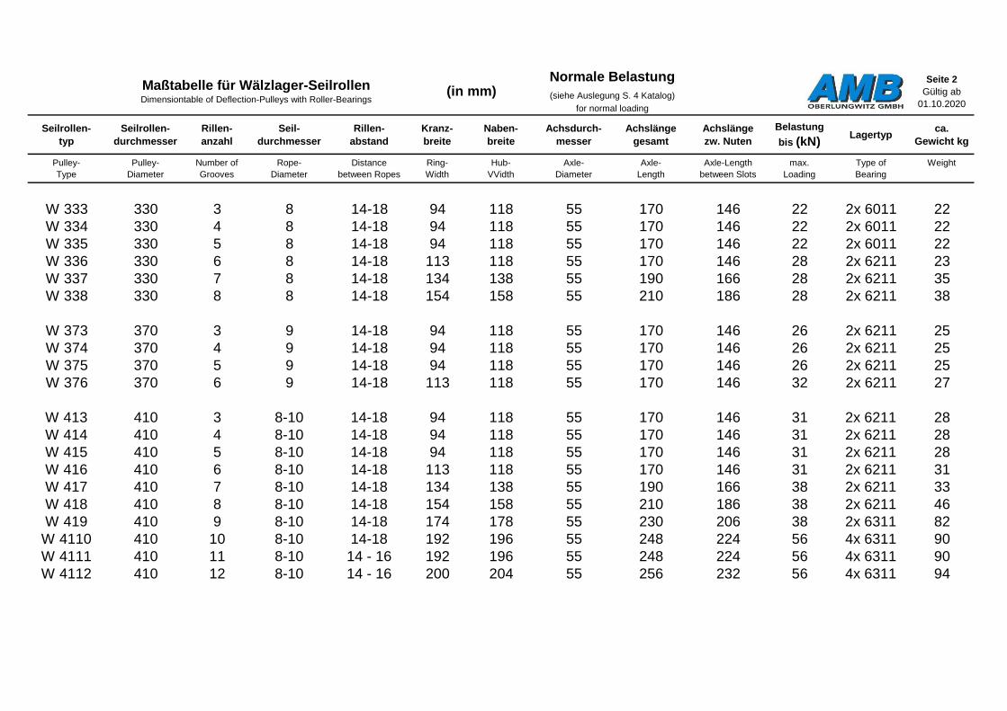
W 333 330 3 8 14-18 94 118 55 170 146 22 2x 6011 22
W 334 330 4 8 14-18 94 118 55 170 146 22 2x 6011 22
W 335 330 5 8 14-18 94 118 55 170 146 22 2x 6011 22
W 336 330 6 8 14-18 113 118 55 170 146 28 2x 6211 23
W 337 330 7 8 14-18 134 138 55 190 166 28 2x 6211 35
W 338 330 8 8 14-18 154 158 55 210 186 28 2x 6211 38
W 373 370 3 9 14-18 94 118 55 170 146 26 2x 6211 25
W 374 370 4 9 14-18 94 118 55 170 146 26 2x 6211 25
W 375 370 5 9 14-18 94 118 55 170 146 26 2x 6211 25
W 376 370 6 9 14-18 113 118 55 170 146 32 2x 6211 27
W 413 410 3 8-10 14-18 94 118 55 170 146 31 2x 6211 28
W 414 410 4 8-10 14-18 94 118 55 170 146 31 2x 6211 28
W 415 410 5 8-10 14-18 94 118 55 170 146 31 2x 6211 28
W 416 410 6 8-10 14-18 113 118 55 170 146 31 2x 6211 31
W 417 410 7 8-10 14-18 134 138 55 190 166 38 2x 6211 33
W 418 410 8 8-10 14-18 154 158 55 210 186 38 2x 6211 46
W 419 410 9 8-10 14-18 174 178 55 230 206 38 2x 6311 82
W 4110 410 10 8-10 14-18 192 196 55 248 224 56 4x 6311 90
W 4111 410 11 8-10 14 - 16 192 196 55 248 224 56 4x 6311 90
W 4112 410 12 8-10 14 - 16 200 204 55 256 232 56 4x 6311 94
Maßtabelle für Wälzlager-SeilrollenDimensiontable of Deflection-Pulleys with Roller-Bearings
(in mm)Normale Belastung
(siehe Auslegung S. 4 Katalog)
for normal loading

Seite 3
Gültig ab
01.10.2020
Seilrollen-
typ
Seilrollen-
durchmesser
Rillen-
anzahl
Seil-
durchmesser
Rillen-
abstand
Kranz-
breite
Naben-
breite
Achsdurch-
messer
Achslänge
gesamt
Achslänge
zw. Nuten
Belastung
bis (kN)Lagertyp
ca.
Gewicht kg
Pulley-
Type
Pulley-
Diameter
Number of
Grooves
Rope-
Diameter
Distance
between Ropes
Ring-
Width
Hub-
VVidth
Axle-
Diameter
Axle-
Length
Axle-Length
between Slots
max.
Loading
Type of
Bearing
Weight
W 453 450 3 8-11 14-18 94 118 55 170 146 34 2x 6211 32
W 454 450 4 8-11 14-18 94 118 55 170 146 34 2x 6211 32
W 455 450 5 8-11 14-18 96 118 55 170 146 34 2x 6211 32
W 456 450 6 8-11 14-18 113 118 55 170 146 43 3x 6211 38
W 457 450 7 8-11 14-18 134 138 55 190 166 43 3x 6211 44
W 458 450 8 8-11 14-18 154 158 55 210 186 48 2x 6311 68
W 459 450 9 8-11 14-18 174 178 55 230 206 48 2x 6311 90
W 463 460 3 8-11 14-18 94 118 55 170 146 39 2x 6211 33
W 464 460 4 8-11 14-18 94 118 55 170 146 39 2x 6211 33
W 465 460 5 8-11 14-18 96 118 55 170 146 39 2x 6211 33
W 466 460 6 8-11 14-18 113 118 55 170 146 48 3x 6211 41
W 467 460 7 8-11 14-18 134 138 55 190 166 48 3x 6211 46
W 468 460 8 8-11 14-18 154 158 55 210 186 48 2x 6311 85
W 469 460 9 8-11 14-18 174 178 55 230 206 48 2x 6311 90
W 482 480 2 10-12 16-18 91 95 55 147 123 35 2x 6211 48
W 483 480 3 10-12 16-18 91 95 55 147 123 35 2x 6211 48
W 484 480 4 10-12 16-18 91 95 55 147 123 35 2x 6211 48
W 485 480 5 10-12 16-18 113 118 60 170 146 66 2x 6312 55
W 486 480 6 10-12 16-18 113 118 60 170 146 66 2x 6312 55
W 487 480 7 10-12 16-18 134 138 60 190 166 66 2x 6312 65
W 488 480 8 10-12 16-18 154 158 60 210 186 66 2x 6312 80
W 489 480 9 10-12 16-18 172 178 60 230 206 66 2x 6312 96
Maßtabelle für Wälzlager-SeilrollenDimensiontable of Deflection-Pulleys with Roller-Bearings
(in mm)Normale Belastung
(siehe Auslegung S. 4 Katalog)
for normal loading

Seite 4
Gültig ab
01.10.2020
Seilrollen-
typ
Seilrollen-
durchmesser
Rillen-
anzahl
Seil-
durchmesser
Rillen-
abstand
Kranz-
breite
Naben-
breite
Achsdurch-
messer
Achslänge
gesamt
Achslänge
zw. Nuten
Belastung
bis (kN)Lagertyp
ca.
Gewicht kg
Pulley-
Type
Pulley-
Diameter
Number of
Grooves
Rope-
Diameter
Distance
between Ropes
Ring-
Width
Hub-
VVidth
Axle-
Diameter
Axle-
Length
Axle-Length
between Slots
max.
Loading
Type of
Bearing
Weight
W 513 510 3 10-12 16-18 94 118 55 170 146 39 2x 6211 34
W 514 510 4 10-12 16-18 94 118 55 170 146 39 2x 6211 34
W 515 510 5 10-12 16-18 94 118 55 170 146 48 3x 6211 34
W 516 510 6 10-12 16-18 113 118 55 170 146 48 3x 6211 43
W 517 510 7 10-12 16-18 134 138 55 190 166 48 3x 6211 48
W 518 510 8 10-12 16-18 154 158 55 210 186 59 2x 6311 65
W 522 520 2 10-13 16-18 91 95 55 147 123 41 2x 6211 55
W 523 520 3 10-13 16-18 94 118 55 170 146 41 2x 6211 60
W 524 520 4 10-13 16-18 94 118 55 170 146 41 2x 6211 60
W 525 520 5 10-13 16-18 94 118 55 170 146 41 2x 6211 60
W 526 520 6 10-13 16-18 113 118 55 170 146 41 2x 6211 65
W 527 520 7 10-13 16-18 134 138 55 190 166 50 3x 6211 75
W 528 520 8 10-13 16-18 154 158 55 210 186 50 4x 6211 80
W 529 520 9 10-13 16-18 174 178 60 230 206 68 2x 6312 100
W 533 530 3 10-13 16-18 94 118 55 170 146 41 2x 6211 60
W 534 530 4 10-13 16-18 94 118 55 170 146 41 2x 6211 60
W 535 530 5 10-13 16-18 94 118 55 170 146 41 2x 6211 60
W 536 530 6 10-13 16-18 113 118 55 170 146 41 2x 6211 65
W 537 530 7 10-13 16-18 134 138 55 190 166 50 3x 6211 75
W 538 530 8 10-13 16-18 154 158 55 210 186 50 3x 6211 80
Maßtabelle für Wälzlager-SeilrollenDimensiontable of Deflection-Pulleys with Roller-Bearings
(in mm)Normale Belastung
(siehe Auslegung S. 4 Katalog)
for normal loading

Seite 5
Gültig ab
01.10.2020
Seilrollen-
typ
Seilrollen-
durchmesser
Rillen-
anzahl
Seil-
durchmesser
Rillen-
abstand
Kranz-
breite
Naben-
breite
Achsdurch-
messer
Achslänge
gesamt
Achslänge
zw. Nuten
Belastung
bis (kN)Lagertyp
ca.
Gewicht kg
Pulley-
Type
Pulley-
Diameter
Number of
Grooves
Rope-
Diameter
Distance
between Ropes
Ring-
Width
Hub-
VVidth
Axle-
Diameter
Axle-
Length
Axle-Length
between Slots
max.
Loading
Type of
Bearing
Weight
W563 560 3 10-13 16-18 94 118 55 170 146 39 2x 6211 41
W564 560 4 10-13 16-18 94 118 55 170 146 39 2x 6211 41
W565 560 5 10-13 16-18 96 118 55 170 146 39 2x 6211 41
W566 560 6 10-13 16-18 113 118 55 170 146 39 2x 6211 52
W567 560 7 10-13 16-18 134 138 55 190 166 48 3x 6211 67
W568 560 8 10-13 16-18 154 158 55 210 186 48 3x 6211 72
W613 610 3 12-15 16-18 94 118 55 170 146 39 2x 6211 61
W614 610 4 12-15 16-18 94 118 55 170 146 39 2x 6211 61
W615 610 5 12-15 16-18 96 118 55 170 146 39 2x 6211 61
W616 610 6 12-15 16-18 113 118 55 170 146 48 3x 6211 65
W617 610 7 12-15 16-18 134 138 55 190 166 48 3x 6211 73
W618 611 8 12-15 16-18 154 158 55 210 186 62 2x 6311 83
W653 650 3 13-16 16-18 94 118 55 170 146 39 2x 6211 78
W654 650 4 13-16 16-18 94 118 55 170 146 39 2x 6211 78
W655 650 5 13-16 16-18 96 118 55 170 146 39 2x 6211 78
W656 650 6 13-16 16-18 113 118 55 170 146 48 3x 6211 84
W657 650 7 13-16 16-18 134 138 55 190 166 48 3x 6211 93
W658 650 8 13-16 16-18 154 158 55 210 186 48 3x 6211 102
W659 650 9 13-16 16-18 174 178 55 230 206 48 3x 6211 112
W663 660 3 13-16 16-18 94 118 55 170 146 39 2x 6211 80
W664 660 4 13-16 16-18 113 118 55 170 146 39 2x 6211 88
W665 660 5 13-16 16-18 113 118 55 170 146 39 2x 6211 88
W666 660 6 13-16 16-18 134 138 55 190 166 48 3x 6211 98
Maßtabelle für Wälzlager-SeilrollenDimensiontable of Deflection-Pulleys with Roller-Bearings
(in mm)Normale Belastung
(siehe Auslegung S. 4 Katalog)
for normal loading
Seite 6
Gültig ab
01.10.2020
Seilrollen-
typ
Seilrollen-
durchmesser
Rillen-
anzahl
Seil-
durchmesser
Rillen-
abstand
Kranz-
breite
Naben-
breite
Achsdurch-
messer
Achslänge
gesamt
Achslänge
zw. Nuten
Belastung
bis (kN)Lagertyp
ca.
Gewicht kg
Pulley-
Type
Pulley-
Diameter
Number of
Grooves
Rope-
Diameter
Distance
between Ropes
Ring-
Width
Hub-
VVidth
Axle-
Diameter
Axle-
Length
Axle-Length
between Slots
max.
Loading
Type of
Bearing
Weight
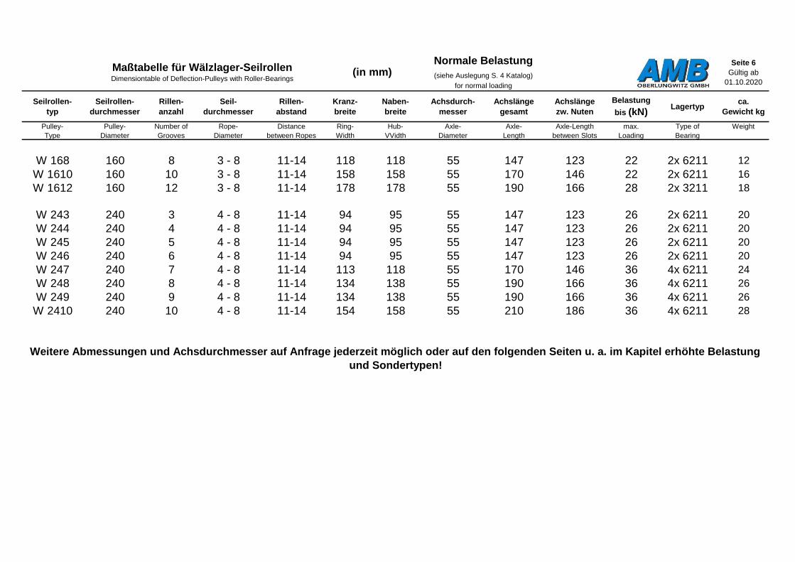
W 168 160 8 3 - 8 11-14 118 118 55 147 123 22 2x 6211 12
W 1610 160 10 3 - 8 11-14 158 158 55 170 146 22 2x 6211 16
W 1612 160 12 3 - 8 11-14 178 178 55 190 166 28 2x 3211 18
W 243 240 3 4 - 8 11-14 94 95 55 147 123 26 2x 6211 20
W 244 240 4 4 - 8 11-14 94 95 55 147 123 26 2x 6211 20
W 245 240 5 4 - 8 11-14 94 95 55 147 123 26 2x 6211 20
W 246 240 6 4 - 8 11-14 94 95 55 147 123 26 2x 6211 20
W 247 240 7 4 - 8 11-14 113 118 55 170 146 36 4x 6211 24
W 248 240 8 4 - 8 11-14 134 138 55 190 166 36 4x 6211 26
W 249 240 9 4 - 8 11-14 134 138 55 190 166 36 4x 6211 26
W 2410 240 10 4 - 8 11-14 154 158 55 210 186 36 4x 6211 28
Maßtabelle für Wälzlager-SeilrollenDimensiontable of Deflection-Pulleys with Roller-Bearings
(in mm)Normale Belastung
(siehe Auslegung S. 4 Katalog)
for normal loading
Weitere Abmessungen und Achsdurchmesser auf Anfrage jederzeit möglich oder auf den folgenden Seiten u. a. im Kapitel erhöhte Belastung
und Sondertypen!
Seite 7
Gültig ab
01.10.2020
Seilrollen-
typ
Seilrollen-
durchmesser
Rillen-
anzahl
Seil-
durchmesser
Rillen-
abstand
Kranz-
breite
Naben-
breite
Achsdurch-
messer
Achslänge
gesamt
Achslänge
zw. Nuten
Belastung
bis (kN)Lagertyp
ca.
Gewicht kg
Pulley-
Type
Pulley-
Diameter
Number of
Grooves
Rope-
Diameter
Distance
between Ropes
Ring-
Width
Hub-
VVidth
Axle-
Diameter
Axle-
Length
Axle-Length
between Slots
max.
Loading
Type of
Bearing
Weight
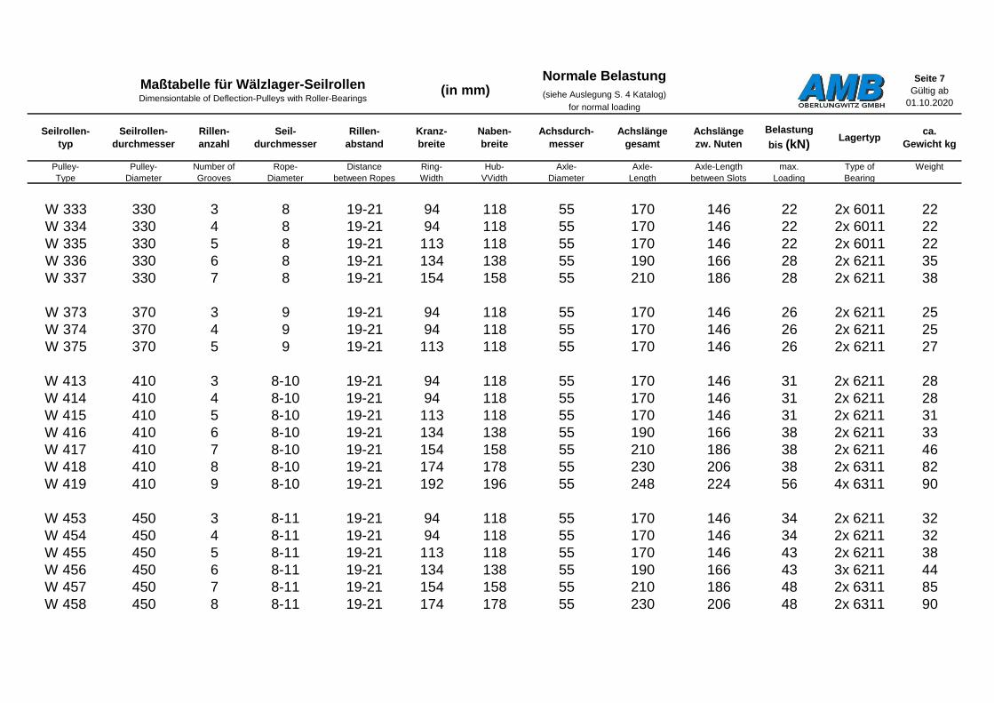
W 333 330 3 8 19-21 94 118 55 170 146 22 2x 6011 22
W 334 330 4 8 19-21 94 118 55 170 146 22 2x 6011 22
W 335 330 5 8 19-21 113 118 55 170 146 22 2x 6011 22
W 336 330 6 8 19-21 134 138 55 190 166 28 2x 6211 35
W 337 330 7 8 19-21 154 158 55 210 186 28 2x 6211 38
W 373 370 3 9 19-21 94 118 55 170 146 26 2x 6211 25
W 374 370 4 9 19-21 94 118 55 170 146 26 2x 6211 25
W 375 370 5 9 19-21 113 118 55 170 146 26 2x 6211 27
W 413 410 3 8-10 19-21 94 118 55 170 146 31 2x 6211 28
W 414 410 4 8-10 19-21 94 118 55 170 146 31 2x 6211 28
W 415 410 5 8-10 19-21 113 118 55 170 146 31 2x 6211 31
W 416 410 6 8-10 19-21 134 138 55 190 166 38 2x 6211 33
W 417 410 7 8-10 19-21 154 158 55 210 186 38 2x 6211 46
W 418 410 8 8-10 19-21 174 178 55 230 206 38 2x 6311 82
W 419 410 9 8-10 19-21 192 196 55 248 224 56 4x 6311 90
W 453 450 3 8-11 19-21 94 118 55 170 146 34 2x 6211 32
W 454 450 4 8-11 19-21 94 118 55 170 146 34 2x 6211 32
W 455 450 5 8-11 19-21 113 118 55 170 146 43 2x 6211 38
W 456 450 6 8-11 19-21 134 138 55 190 166 43 3x 6211 44
W 457 450 7 8-11 19-21 154 158 55 210 186 48 2x 6311 85
W 458 450 8 8-11 19-21 174 178 55 230 206 48 2x 6311 90
Maßtabelle für Wälzlager-SeilrollenDimensiontable of Deflection-Pulleys with Roller-Bearings
(in mm)Normale Belastung
(siehe Auslegung S. 4 Katalog)
for normal loading
Seite 8
Gültig ab
01.10.2020
Seilrollen-
typ
Seilrollen-
durchmesser
Rillen-
anzahl
Seil-
durchmesser
Rillen-
abstand
Kranz-
breite
Naben-
breite
Achsdurch-
messer
Achslänge
gesamt
Achslänge
zw. Nuten
Belastung
bis (kN)Lagertyp
ca.
Gewicht kg
Pulley-
Type
Pulley-
Diameter
Number of
Grooves
Rope-
Diameter
Distance
between Ropes
Ring-
Width
Hub-
VVidth
Axle-
Diameter
Axle-
Length
Axle-Length
between Slots
max.
Loading
Type of
Bearing
Weight
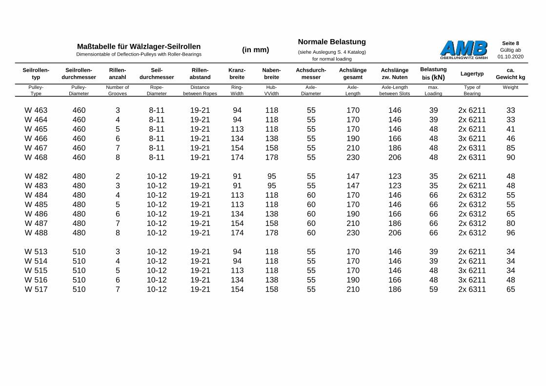
W 463 460 3 8-11 19-21 94 118 55 170 146 39 2x 6211 33
W 464 460 4 8-11 19-21 94 118 55 170 146 39 2x 6211 33
W 465 460 5 8-11 19-21 113 118 55 170 146 48 2x 6211 41
W 466 460 6 8-11 19-21 134 138 55 190 166 48 3x 6211 46
W 467 460 7 8-11 19-21 154 158 55 210 186 48 2x 6311 85
W 468 460 8 8-11 19-21 174 178 55 230 206 48 2x 6311 90
W 482 480 2 10-12 19-21 91 95 55 147 123 35 2x 6211 48
W 483 480 3 10-12 19-21 91 95 55 147 123 35 2x 6211 48
W 484 480 4 10-12 19-21 113 118 60 170 146 66 2x 6312 55
W 485 480 5 10-12 19-21 113 118 60 170 146 66 2x 6312 55
W 486 480 6 10-12 19-21 134 138 60 190 166 66 2x 6312 65
W 487 480 7 10-12 19-21 154 158 60 210 186 66 2x 6312 80
W 488 480 8 10-12 19-21 174 178 60 230 206 66 2x 6312 96
W 513 510 3 10-12 19-21 94 118 55 170 146 39 2x 6211 34
W 514 510 4 10-12 19-21 94 118 55 170 146 39 2x 6211 34
W 515 510 5 10-12 19-21 113 118 55 170 146 48 3x 6211 34
W 516 510 6 10-12 19-21 134 138 55 190 166 48 3x 6211 48
W 517 510 7 10-12 19-21 154 158 55 210 186 59 2x 6311 65
Maßtabelle für Wälzlager-SeilrollenDimensiontable of Deflection-Pulleys with Roller-Bearings
(in mm)Normale Belastung
(siehe Auslegung S. 4 Katalog)
for normal loading

Seite 9
Gültig ab
01.10.2020
Seilrollen-
typ
Seilrollen-
durchmesser
Rillen-
anzahl
Seil-
durchmesser
Rillen-
abstand
Kranz-
breite
Naben-
breite
Achsdurch-
messer
Achslänge
gesamt
Achslänge
zw. Nuten
Belastung
bis (kN)Lagertyp
ca.
Gewicht kg
Pulley-
Type
Pulley-
Diameter
Number of
Grooves
Rope-
Diameter
Distance
between Ropes
Ring-
Width
Hub-
VVidth
Axle-
Diameter
Axle-
Length
Axle-Length
between Slots
max.
Loading
Type of
Bearing
Weight
W 522 520 2 10-13 19-21 91 95 55 147 123 41 2x 6211 55
W 523 520 3 10-13 19-21 94 118 55 170 146 41 2x 6211 60
W 524 520 4 10-13 19-21 94 118 55 170 146 41 2x 6211 60
W 525 520 5 10-13 19-21 113 118 55 170 146 41 2x 6211 65
W 526 520 6 10-13 19-21 134 138 55 190 166 41 2x 6211 75
W 527 520 7 10-13 19-21 154 158 55 210 186 50 4x 6211 80
W 528 520 8 10-13 19-21 174 178 60 230 206 68 2x 6312 100
W 533 530 3 10-13 19-21 94 118 55 170 146 41 2x 6211 60
W 534 530 4 10-13 19-21 94 118 55 170 146 41 2x 6211 60
W 535 530 5 10-13 19-21 113 118 55 170 146 41 2x 6211 65
W 536 530 6 10-13 19-21 134 138 55 190 166 50 3x 6211 75
W 537 530 7 10-13 19-21 154 158 55 210 186 50 3x 6211 80
W563 560 3 10-13 19-21 94 118 55 170 146 39 2x 6211 41
W564 560 4 10-13 19-21 94 118 55 170 146 39 2x 6211 41
W565 560 5 10-13 19-21 113 118 55 170 146 39 2x 6211 52
W566 560 6 10-13 19-21 134 138 55 190 166 48 3x 6211 67
W567 560 7 10-13 19-21 154 158 55 210 186 48 3x 6211 72
Maßtabelle für Wälzlager-SeilrollenDimensiontable of Deflection-Pulleys with Roller-Bearings
(in mm)Normale Belastung
(siehe Auslegung S. 4 Katalog)
for normal loading
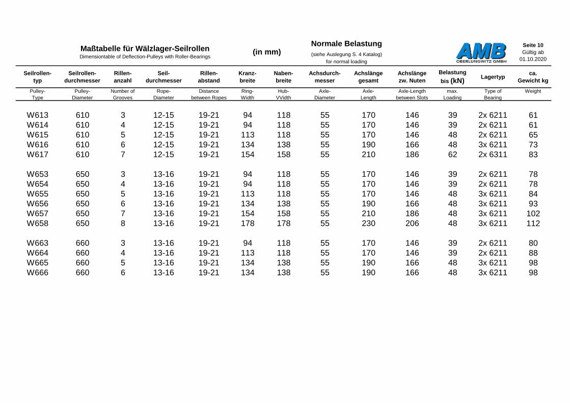
Seite 10
Gültig ab
01.10.2020
Seilrollen-
typ
Seilrollen-
durchmesser
Rillen-
anzahl
Seil-
durchmesser
Rillen-
abstand
Kranz-
breite
Naben-
breite
Achsdurch-
messer
Achslänge
gesamt
Achslänge
zw. Nuten
Belastung
bis (kN)Lagertyp
ca.
Gewicht kg
Pulley-
Type
Pulley-
Diameter
Number of
Grooves
Rope-
Diameter
Distance
between Ropes
Ring-
Width
Hub-
VVidth
Axle-
Diameter
Axle-
Length
Axle-Length
between Slots
max.
Loading
Type of
Bearing
Weight
W613 610 3 12-15 19-21 94 118 55 170 146 39 2x 6211 61
W614 610 4 12-15 19-21 94 118 55 170 146 39 2x 6211 61
W615 610 5 12-15 19-21 113 118 55 170 146 48 2x 6211 65
W616 610 6 12-15 19-21 134 138 55 190 166 48 3x 6211 73
W617 610 7 12-15 19-21 154 158 55 210 186 62 2x 6311 83
W653 650 3 13-16 19-21 94 118 55 170 146 39 2x 6211 78
W654 650 4 13-16 19-21 94 118 55 170 146 39 2x 6211 78
W655 650 5 13-16 19-21 113 118 55 170 146 48 3x 6211 84
W656 650 6 13-16 19-21 134 138 55 190 166 48 3x 6211 93
W657 650 7 13-16 19-21 154 158 55 210 186 48 3x 6211 102
W658 650 8 13-16 19-21 178 178 55 230 206 48 3x 6211 112
W663 660 3 13-16 19-21 94 118 55 170 146 39 2x 6211 80
W664 660 4 13-16 19-21 113 118 55 170 146 39 2x 6211 88
W665 660 5 13-16 19-21 134 138 55 190 166 48 3x 6211 98
W666 660 6 13-16 19-21 134 138 55 190 166 48 3x 6211 98
Maßtabelle für Wälzlager-SeilrollenDimensiontable of Deflection-Pulleys with Roller-Bearings
(in mm)Normale Belastung
(siehe Auslegung S. 4 Katalog)
for normal loading

Seite 11
Gültig ab
01.10.2020
Seilrollen-
typ
Seilrollen-
durchmesser
Rillen-
anzahl
Seil-
durchmesser
Rillen-
abstand
Kranz-
breite
Naben-
breite
Achsdurch-
messer
Achslänge
gesamt
Achslänge
zw. Nuten
Belastung
bis (kN)Lagertyp
ca.
Gewicht kg
Pulley-
Type
Pulley-
Diameter
Number of
Grooves
Rope-
Diameter
Distance
between Ropes
Ring-
Width
Hub-
VVidth
Axle-
Diameter
Axle-
Length
Axle-Length
between Slots
max.
Loading
Type of
Bearing
Weight
WE 168 160 8 3 - 7,5 6 -10 118 118 55 147 123 31 4x 6211 13
WE 1610 160 10 3 - 7,5 6 -10 118 118 55 170 146 31 4x 6211 14
WE 1612 160 12 3 - 7,5 6 -10 138 138 55 190 166 38 4x 6211 16
WE 1614 160 14 3 - 7,5 6 -10 158 158 55 210 186 38 4x 6211 18
WE 243 240 3 4 - 8 6 -10 94 95 60 147 123 34 2x 6212 20
WE 244 240 4 4 - 8 6 -10 94 95 60 147 123 34 2x 6212 20
WE 245 240 5 4 - 8 6 -10 94 95 60 147 123 34 2x 6212 20
WE 246 240 6 4 - 8 6 -10 94 95 60 147 123 34 2x 6212 20
WE 247 240 7 4 - 8 6 -10 94 95 60 147 123 34 2x 6212 20
WE 248 240 8 4 - 8 6 -10 94 95 60 147 123 34 2x 6212 20
WE 249 240 9 4 - 8 6 -10 113 118 60 170 146 34 2x 6212 24
WE 2410 240 10 4 - 8 6 -10 113 118 60 170 146 34 2x 6212 24
WE 2411 240 11 4 - 8 6 -10 134 138 60 190 166 48 4x 6212 26
WE 2412 240 12 4 - 8 6 -10 134 138 60 190 166 48 4x 6212 26
WE 2413 240 13 4 - 8 6 -10 154 158 60 210 186 48 4x 6212 28
WE 2414 240 14 4 - 8 6 -10 154 158 60 210 186 48 4x 6212 28
Weitere Abmessungen und Achsdurchmesser auf Anfrage jederzeit möglich oder auf den folgenden Seiten u. a. im Kapitel erhöhte Belastung
und Sondertypen!
Maßtabelle für Wälzlager-SeilrollenDimensiontable of Deflection-Pulleys with Roller-Bearings
(in mm)Erhöhte Belastung
(siehe Auslegung S. 4 Katalog)
for normal loading

Seite 12
Gültig ab
01.10.2020
Seilrollen-
typ
Seilrollen-
durchmesser
Rillen-
anzahl
Seil-
durchmesser
Rillen-
abstand
Kranz-
breite
Naben-
breite
Achsdurch-
messer
Achslänge
gesamt
Achslänge
zw. Nuten
Belastung
bis (kN)Lagertyp
ca.
Gewicht kg
Pulley-
Type
Pulley-
Diameter
Number of
Grooves
Rope-
Diameter
Distance
between Ropes
Ring-
Width
Hub-
VVidth
Axle-
Diameter
Axle-
Length
Axle-Length
between Slots
max.
Loading
Type of
Bearing
Weight
WE 333 330 3 8 14-18 94 118 55 170 146 28 2x 6211 23
WE 334 330 4 8 14-18 94 118 55 170 146 28 2x 6211 23
WE 335 330 5 8 14-18 94 118 55 170 146 28 2x 6211 23
WE 336 330 6 8 14-18 113 118 55 170 146 31 3x 6211 24
WE 337 330 7 8 14-18 134 138 60 190 166 38 2x 6212 36
WE 338 330 8 8 14-18 154 158 60 210 186 38 2x 6212 39
WE 373 370 3 9 14-18 94 118 60 170 146 39 2x 6212 26
WE 374 370 4 9 14-18 94 118 60 170 146 39 2x 6212 26
WE 375 370 5 9 14-18 96 118 60 170 146 39 2x 6212 26
WE 376 370 6 9 14-18 113 118 60 170 146 39 2x 6212 28
WE 413 410 3 8-10 14-18 94 118 60 170 146 48 2x 6212 29
WE 414 410 4 8-10 14-18 94 118 60 170 146 48 2x 6212 29
WE 415 410 5 8-10 14-18 94 118 60 170 146 48 2x 6212 29
WE 416 410 6 8-10 14-18 113 118 60 170 146 56 3x 6212 32
WE 417 410 7 8-10 14-18 134 138 60 190 166 60 2x 3212 41
WE 418 410 8 8-10 14-18 154 158 60 210 186 60 2x 3212 47
WE 419 410 9 8-10 14-18 174 178 60 230 206 60 2x 3212 82
WE 4110 410 10 8-10 14-18 192 196 60 248 224 80 4x 6312 90
WE 4111 410 11 8-10 14 - 16 192 196 60 248 224 80 4x 6312 90
WE 4112 410 12 8-10 14 - 16 200 204 60 256 232 80 4x 6312 94
Maßtabelle für Wälzlager-SeilrollenDimensiontable of Deflection-Pulleys with Roller-Bearings
(in mm)Erhöhte Belastung
(siehe Auslegung S. 4 Katalog)
for normal loading

Seite 13
Gültig ab
01.10.2020
Seilrollen-
typ
Seilrollen-
durchmesser
Rillen-
anzahl
Seil-
durchmesser
Rillen-
abstand
Kranz-
breite
Naben-
breite
Achsdurch-
messer
Achslänge
gesamt
Achslänge
zw. Nuten
Belastung
bis (kN)Lagertyp
ca.
Gewicht kg
Pulley-
Type
Pulley-
Diameter
Number of
Grooves
Rope-
Diameter
Distance
between Ropes
Ring-
Width
Hub-
VVidth
Axle-
Diameter
Axle-
Length
Axle-Length
between Slots
max.
Loading
Type of
Bearing
Weight
WE 453 450 3 8-11 14-18 94 118 60 170 146 48 2x 6212 34
WE 454 450 4 8-11 14-18 94 118 60 170 146 48 2x 6212 34
WE 455 450 5 8-11 14-18 96 118 60 170 146 48 2x 6212 34
WE 456 450 6 8-11 14-18 113 118 60 170 146 56 3x 6212 40
WE 457 450 7 8-11 14-18 134 138 60 190 166 60 2x 3212 46
WE 458 450 8 8-11 14-18 154 158 70 210 186 100 2x 22214 85
WE 459 450 9 8-11 14-18 174 178 70 230 206 110 2x 22214 90
WE 463 460 3 8-11 14-18 94 118 60 170 146 48 2x 6212 35
WE 464 460 4 8-11 14-18 94 118 60 170 146 48 2x 6212 35
WE 465 460 5 8-11 14-18 96 118 60 170 146 48 2x 6212 35
WE 466 460 6 8-11 14-18 113 118 60 170 146 56 3x 6212 42
WE 467 460 7 8-11 14-18 134 138 60 190 166 60 2x 3212 49
WE 468 460 8 8-11 14-18 154 158 70 210 186 100 2x 22214 85
WE 469 460 9 8-11 14-18 174 178 70 230 206 100 2x 22214 90
WE 4610 460 10 8-11 14-17 180 184 70 236 212 100 2x 22214 93
WE 482 480 2 10-12 16-18 91 95 60 147 123 47 2x 6212 49
WE 483 480 3 10-12 16-18 91 95 60 147 123 47 2x 6212 49
WE 484 480 4 10-12 16-18 91 95 60 147 123 47 2x 6212 49
WE 485 480 5 10-12 16-18 113 118 60 170 146 66 2x 6312 55
WE 486 480 6 10-12 16-18 113 118 60 170 146 66 2x 6312 55
WE 487 480 7 10-12 16-18 134 138 60 190 166 66 2x 6312 67
WE 488 480 8 10-12 16-18 154 158 80 210 186 110 2x 22216 83
WE 489 480 9 10-12 16-18 174 178 80 230 206 110 2x 22216 99
Maßtabelle für Wälzlager-SeilrollenDimensiontable of Deflection-Pulleys with Roller-Bearings
(in mm)Erhöhte Belastung
(siehe Auslegung S. 4 Katalog)
for normal loading
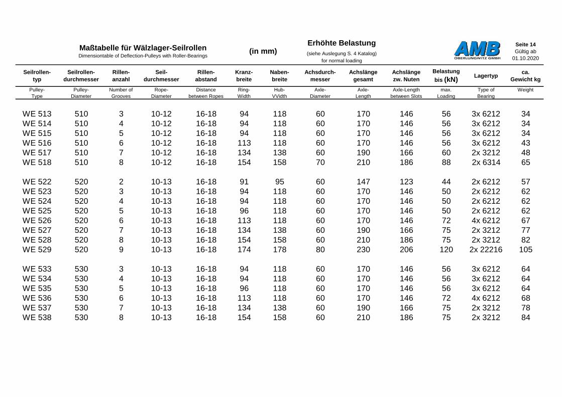
Seite 14
Gültig ab
01.10.2020
Seilrollen-
typ
Seilrollen-
durchmesser
Rillen-
anzahl
Seil-
durchmesser
Rillen-
abstand
Kranz-
breite
Naben-
breite
Achsdurch-
messer
Achslänge
gesamt
Achslänge
zw. Nuten
Belastung
bis (kN)Lagertyp
ca.
Gewicht kg
Pulley-
Type
Pulley-
Diameter
Number of
Grooves
Rope-
Diameter
Distance
between Ropes
Ring-
Width
Hub-
VVidth
Axle-
Diameter
Axle-
Length
Axle-Length
between Slots
max.
Loading
Type of
Bearing
Weight
WE 513 510 3 10-12 16-18 94 118 60 170 146 56 3x 6212 34
WE 514 510 4 10-12 16-18 94 118 60 170 146 56 3x 6212 34
WE 515 510 5 10-12 16-18 94 118 60 170 146 56 3x 6212 34
WE 516 510 6 10-12 16-18 113 118 60 170 146 56 3x 6212 43
WE 517 510 7 10-12 16-18 134 138 60 190 166 60 2x 3212 48
WE 518 510 8 10-12 16-18 154 158 70 210 186 88 2x 6314 65
WE 522 520 2 10-13 16-18 91 95 60 147 123 44 2x 6212 57
WE 523 520 3 10-13 16-18 94 118 60 170 146 50 2x 6212 62
WE 524 520 4 10-13 16-18 94 118 60 170 146 50 2x 6212 62
WE 525 520 5 10-13 16-18 96 118 60 170 146 50 2x 6212 62
WE 526 520 6 10-13 16-18 113 118 60 170 146 72 4x 6212 67
WE 527 520 7 10-13 16-18 134 138 60 190 166 75 2x 3212 77
WE 528 520 8 10-13 16-18 154 158 60 210 186 75 2x 3212 82
WE 529 520 9 10-13 16-18 174 178 80 230 206 120 2x 22216 105
WE 533 530 3 10-13 16-18 94 118 60 170 146 56 3x 6212 64
WE 534 530 4 10-13 16-18 94 118 60 170 146 56 3x 6212 64
WE 535 530 5 10-13 16-18 96 118 60 170 146 56 3x 6212 64
WE 536 530 6 10-13 16-18 113 118 60 170 146 72 4x 6212 68
WE 537 530 7 10-13 16-18 134 138 60 190 166 75 2x 3212 78
WE 538 530 8 10-13 16-18 154 158 60 210 186 75 2x 3212 84
Maßtabelle für Wälzlager-SeilrollenDimensiontable of Deflection-Pulleys with Roller-Bearings
(in mm)Erhöhte Belastung
(siehe Auslegung S. 4 Katalog)
for normal loading
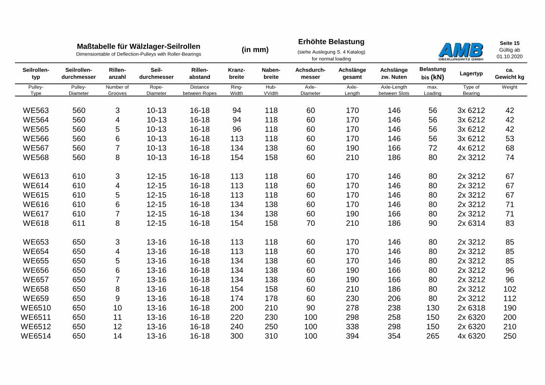
Seite 15
Gültig ab
01.10.2020
Seilrollen-
typ
Seilrollen-
durchmesser
Rillen-
anzahl
Seil-
durchmesser
Rillen-
abstand
Kranz-
breite
Naben-
breite
Achsdurch-
messer
Achslänge
gesamt
Achslänge
zw. Nuten
Belastung
bis (kN)Lagertyp
ca.
Gewicht kg
Pulley-
Type
Pulley-
Diameter
Number of
Grooves
Rope-
Diameter
Distance
between Ropes
Ring-
Width
Hub-
VVidth
Axle-
Diameter
Axle-
Length
Axle-Length
between Slots
max.
Loading
Type of
Bearing
Weight
WE563 560 3 10-13 16-18 94 118 60 170 146 56 3x 6212 42
WE564 560 4 10-13 16-18 94 118 60 170 146 56 3x 6212 42
WE565 560 5 10-13 16-18 96 118 60 170 146 56 3x 6212 42
WE566 560 6 10-13 16-18 113 118 60 170 146 56 3x 6212 53
WE567 560 7 10-13 16-18 134 138 60 190 166 72 4x 6212 68
WE568 560 8 10-13 16-18 154 158 60 210 186 80 2x 3212 74
WE613 610 3 12-15 16-18 113 118 60 170 146 80 2x 3212 67
WE614 610 4 12-15 16-18 113 118 60 170 146 80 2x 3212 67
WE615 610 5 12-15 16-18 113 118 60 170 146 80 2x 3212 67
WE616 610 6 12-15 16-18 134 138 60 170 146 80 2x 3212 71
WE617 610 7 12-15 16-18 134 138 60 190 166 80 2x 3212 71
WE618 611 8 12-15 16-18 154 158 70 210 186 90 2x 6314 83
WE653 650 3 13-16 16-18 113 118 60 170 146 80 2x 3212 85
WE654 650 4 13-16 16-18 113 118 60 170 146 80 2x 3212 85
WE655 650 5 13-16 16-18 134 138 60 170 146 80 2x 3212 85
WE656 650 6 13-16 16-18 134 138 60 190 166 80 2x 3212 96
WE657 650 7 13-16 16-18 134 138 60 190 166 80 2x 3212 96
WE658 650 8 13-16 16-18 154 158 60 210 186 80 2x 3212 102
WE659 650 9 13-16 16-18 174 178 60 230 206 80 2x 3212 112
WE6510 650 10 13-16 16-18 200 210 90 278 238 130 2x 6318 190
WE6511 650 11 13-16 16-18 220 230 100 298 258 150 2x 6320 200
WE6512 650 12 13-16 16-18 240 250 100 338 298 150 2x 6320 210
WE6514 650 14 13-16 16-18 300 310 100 394 354 265 4x 6320 250
Maßtabelle für Wälzlager-SeilrollenDimensiontable of Deflection-Pulleys with Roller-Bearings
(in mm)Erhöhte Belastung
(siehe Auslegung S. 4 Katalog)
for normal loading

Seite 16
Gültig ab
01.10.2020
Seilrollen-
typ
Seilrollen-
durchmesser
Rillen-
anzahl
Seil-
durchmesser
Rillen-
abstand
Kranz-
breite
Naben-
breite
Achsdurch-
messer
Achslänge
gesamt
Achslänge
zw. Nuten
Belastung
bis (kN)Lagertyp
ca.
Gewicht kg
Pulley-
Type
Pulley-
Diameter
Number of
Grooves
Rope-
Diameter
Distance
between Ropes
Ring-
Width
Hub-
VVidth
Axle-
Diameter
Axle-
Length
Axle-Length
between Slots
max.
Loading
Type of
Bearing
Weight
WE663 660 3 13-16 16-18 113 118 60 170 146 80 2x 3212 90
WE664 660 4 13-16 16-18 113 118 60 170 146 80 2x 3212 90
WE665 660 5 13-16 16-18 134 138 60 190 166 80 2x 3212 90
WE666 660 6 13-16 16-18 134 138 60 190 166 80 2x 3212 100
WE667 660 7 13-16 16-18 134 138 60 190 166 80 2x 3212 100
WE806 800 6 13-20 16-22 170 180 90 268 228 140 2x 6318 380
WE807 800 7 13-20 16-22 195 205 90 293 253 140 2x 6318 400
WE808 800 8 13-20 16-22 220 230 100 318 278 160 2x 6320 425
WE809 800 9 13-20 16-22 245 255 100 343 303 160 2x 6320 450
WE8010 800 10 13-20 16-22 270 280 100 368 328 285 4x 6320 470
WE816 810 6 13-20 16-22 170 180 90 268 228 140 2x 6318 380
WE817 810 7 13-20 16-22 195 205 90 293 253 140 2x 6318 400
WE818 810 8 13-20 16-22 220 230 100 318 278 160 2x 6320 425
WE819 810 9 13-20 16-22 245 255 100 343 303 160 2x 6320 450
WE8110 810 10 13-20 16-22 270 280 100 368 328 285 4x 6320 470
Maßtabelle für Wälzlager-SeilrollenDimensiontable of Deflection-Pulleys with Roller-Bearings
(in mm)Erhöhte Belastung
(siehe Auslegung S. 4 Katalog)
for normal loading

Seite 17
Gültig ab
01.10.2020
Seilrollen-
typ
Seilrollen-
durchmesser
Rillen-
anzahl
Seil-
durchmesser
Rillen-
abstand
Kranz-
breite
Naben-
breite
Achsdurch-
messer
Achslänge
gesamt
Achslänge
zw. Nuten
Belastung
bis (kN)Lagertyp
ca.
Gewicht kg
Pulley-
Type
Pulley-
Diameter
Number of
Grooves
Rope-
Diameter
Distance
between Ropes
Ring-
Width
Hub-
VVidth
Axle-
Diameter
Axle-
Length
Axle-Length
between Slots
max.
Loading
Type of
Bearing
Weight
WE 168 160 8 3 - 8 11-14 118 118 55 147 123 31 4x 6211 13
WE 1610 160 10 3 - 8 11-14 158 158 55 170 146 31 4x 6211 14
WE 1612 160 12 3 - 8 11-14 178 178 55 190 166 38 4x 6211 16
WE 243 240 3 4 - 8 11-14 94 95 60 147 123 34 2x 6212 20
WE 244 240 4 4 - 8 11-14 94 95 60 147 123 34 2x 6212 20
WE 245 240 5 4 - 8 11-14 94 95 60 147 123 34 2x 6212 20
WE 246 240 6 4 - 8 11-14 94 95 60 147 123 34 2x 6212 20
WE 247 240 7 4 - 8 11-14 113 118 60 170 146 34 2x 6212 24
WE 248 240 8 4 - 8 11-14 134 138 60 190 166 48 4x 6212 26
WE 249 240 9 4 - 8 11-14 134 138 60 190 166 48 4x 6212 26
WE 2410 240 10 4 - 8 11-14 154 158 60 210 186 48 4x 6212 28
Maßtabelle für Wälzlager-SeilrollenDimensiontable of Deflection-Pulleys with Roller-Bearings
(in mm)Erhöhte Belastung
(siehe Auslegung S. 4 Katalog)
for normal loading
Weitere Abmessungen und Achsdurchmesser auf Anfrage jederzeit möglich oder auf den folgenden Seiten u. a. im Kapitel erhöhte Belastung und
Sondertypen!

Seite 18
Gültig ab
01.10.2020
Seilrollen-
typ
Seilrollen-
durchmesser
Rillen-
anzahl
Seil-
durchmesser
Rillen-
abstand
Kranz-
breite
Naben-
breite
Achsdurch-
messer
Achslänge
gesamt
Achslänge
zw. Nuten
Belastung
bis (kN)Lagertyp
ca.
Gewicht kg
Pulley-
Type
Pulley-
Diameter
Number of
Grooves
Rope-
Diameter
Distance
between Ropes
Ring-
Width
Hub-
VVidth
Axle-
Diameter
Axle-
Length
Axle-Length
between Slots
max.
Loading
Type of
Bearing
Weight
WE 333 330 3 8 19-21 94 118 55 170 146 28 2x 6211 23
WE 334 330 4 8 19-21 94 118 55 170 146 28 2x 6211 23
WE 335 330 5 8 19-21 113 118 55 170 146 31 3x 6211 23
WE 336 330 6 8 19-21 134 138 60 190 166 38 2x 6212 36
WE 337 330 7 8 19-21 154 158 60 210 186 38 2x 6212 39
WE 373 370 3 9 19-21 94 118 60 170 146 39 2x 6212 26
WE 374 370 4 9 19-21 94 118 60 170 146 39 2x 6212 26
WE 375 370 5 9 19-21 113 118 60 170 146 39 2x 6212 28
WE 413 410 3 8-10 19-21 94 118 60 170 146 48 2x 6212 29
WE 414 410 4 8-10 19-21 94 118 60 170 146 48 2x 6212 29
WE 415 410 5 8-10 19-21 113 118 60 170 146 56 3x 6212 32
WE 416 410 6 8-10 19-21 134 138 60 190 166 80 2x 3212 41
WE 417 410 7 8-10 19-21 154 158 60 210 186 80 2x 3212 47
WE 419 410 9 8-10 19-21 174 178 60 230 206 60 2x 3212 82
WE 4110 410 10 8-10 19-21 192 196 60 248 224 80 4x 6312 90
WE 453 450 3 8-11 19-21 94 118 60 170 146 48 2x 6212 34
WE 454 450 4 8-11 19-21 94 118 60 170 146 48 2x 6212 34
WE 455 450 5 8-11 19-21 113 118 60 170 146 56 3x 6212 40
WE 456 450 6 8-11 19-21 134 138 60 190 166 75 2x 3212 46
WE 457 450 7 8-11 19-21 154 158 70 210 186 100 2x 22214 85
WE 458 450 8 8-11 19-21 174 178 70 230 206 100 2x 22214 90
Maßtabelle für Wälzlager-SeilrollenDimensiontable of Deflection-Pulleys with Roller-Bearings
(in mm)Erhöhte Belastung
(siehe Auslegung S. 4 Katalog)
for normal loading
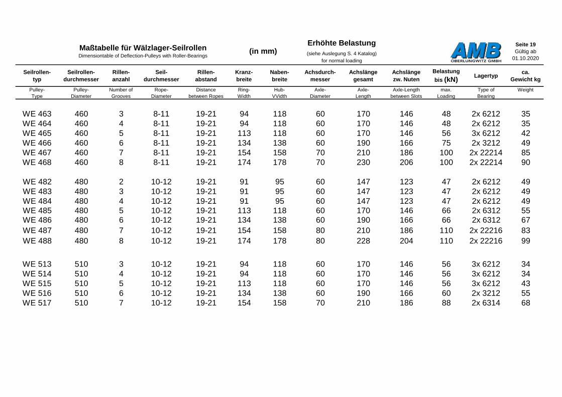
Seite 19
Gültig ab
01.10.2020
Seilrollen-
typ
Seilrollen-
durchmesser
Rillen-
anzahl
Seil-
durchmesser
Rillen-
abstand
Kranz-
breite
Naben-
breite
Achsdurch-
messer
Achslänge
gesamt
Achslänge
zw. Nuten
Belastung
bis (kN)Lagertyp
ca.
Gewicht kg
Pulley-
Type
Pulley-
Diameter
Number of
Grooves
Rope-
Diameter
Distance
between Ropes
Ring-
Width
Hub-
VVidth
Axle-
Diameter
Axle-
Length
Axle-Length
between Slots
max.
Loading
Type of
Bearing
Weight
WE 463 460 3 8-11 19-21 94 118 60 170 146 48 2x 6212 35
WE 464 460 4 8-11 19-21 94 118 60 170 146 48 2x 6212 35
WE 465 460 5 8-11 19-21 113 118 60 170 146 56 3x 6212 42
WE 466 460 6 8-11 19-21 134 138 60 190 166 75 2x 3212 49
WE 467 460 7 8-11 19-21 154 158 70 210 186 100 2x 22214 85
WE 468 460 8 8-11 19-21 174 178 70 230 206 100 2x 22214 90
WE 482 480 2 10-12 19-21 91 95 60 147 123 47 2x 6212 49
WE 483 480 3 10-12 19-21 91 95 60 147 123 47 2x 6212 49
WE 484 480 4 10-12 19-21 91 95 60 147 123 47 2x 6212 49
WE 485 480 5 10-12 19-21 113 118 60 170 146 66 2x 6312 55
WE 486 480 6 10-12 19-21 134 138 60 190 166 66 2x 6312 67
WE 487 480 7 10-12 19-21 154 158 80 210 186 110 2x 22216 83
WE 488 480 8 10-12 19-21 174 178 80 228 204 110 2x 22216 99
WE 513 510 3 10-12 19-21 94 118 60 170 146 56 3x 6212 34
WE 514 510 4 10-12 19-21 94 118 60 170 146 56 3x 6212 34
WE 515 510 5 10-12 19-21 113 118 60 170 146 56 3x 6212 43
WE 516 510 6 10-12 19-21 134 138 60 190 166 60 2x 3212 55
WE 517 510 7 10-12 19-21 154 158 70 210 186 88 2x 6314 68
Maßtabelle für Wälzlager-SeilrollenDimensiontable of Deflection-Pulleys with Roller-Bearings
(in mm)Erhöhte Belastung
(siehe Auslegung S. 4 Katalog)
for normal loading
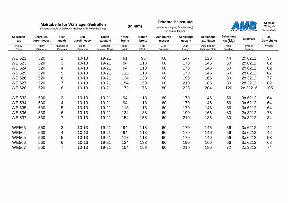
Seite 20
Gültig ab
01.10.2020
Seilrollen-
typ
Seilrollen-
durchmesser
Rillen-
anzahl
Seil-
durchmesser
Rillen-
abstand
Kranz-
breite
Naben-
breite
Achsdurch-
messer
Achslänge
gesamt
Achslänge
zw. Nuten
Belastung
bis (kN)Lagertyp
ca.
Gewicht kg
Pulley-
Type
Pulley-
Diameter
Number of
Grooves
Rope-
Diameter
Distance
between Ropes
Ring-
Width
Hub-
VVidth
Axle-
Diameter
Axle-
Length
Axle-Length
between Slots
max.
Loading
Type of
Bearing
Weight
WE 522 520 2 10-13 19-21 91 95 60 147 123 44 2x 6212 57
WE 523 520 3 10-13 19-21 94 118 60 170 146 50 2x 6212 62
WE 524 520 4 10-13 19-21 94 118 60 170 146 50 2x 6212 62
WE 525 520 5 10-13 19-21 113 118 60 170 146 50 2x 6212 67
WE 526 520 6 10-13 19-21 134 138 60 190 166 80 2x 3212 77
WE 527 520 7 10-13 19-21 154 158 60 210 186 80 2x 3212 82
WE 528 520 8 10-13 19-21 172 176 80 228 204 120 2x 22216 105
WE 533 530 3 10-13 19-21 94 118 60 170 146 56 3x 6212 64
WE 534 530 4 10-13 19-21 94 118 60 170 146 56 3x 6212 64
WE 535 530 5 10-13 19-21 113 118 60 170 146 56 3x 6212 64
WE 536 530 6 10-13 19-21 134 138 60 190 166 80 2x 3212 78
WE 537 530 7 10-13 19-21 154 158 60 210 186 80 2x 3212 84
WE563 560 3 10-13 19-21 94 118 60 170 146 56 3x 6212 42
WE564 560 4 10-13 19-21 94 118 60 170 146 56 3x 6212 42
WE565 560 5 10-13 19-21 113 118 60 170 146 56 3x 6212 53
WE566 560 6 10-13 19-21 134 138 60 190 166 56 3x 6212 68
WE567 560 7 10-13 19-21 154 158 60 210 186 72 2x 3212 74
Maßtabelle für Wälzlager-SeilrollenDimensiontable of Deflection-Pulleys with Roller-Bearings
(in mm)Erhöhte Belastung
(siehe Auslegung S. 4 Katalog)
for normal loading

Seite 21
Gültig ab
01.10.2020
Seilrollen-
typ
Seilrollen-
durchmesser
Rillen-
anzahl
Seil-
durchmesser
Rillen-
abstand
Kranz-
breite
Naben-
breite
Achsdurch-
messer
Achslänge
gesamt
Achslänge
zw. Nuten
Belastung
bis (kN)Lagertyp
ca.
Gewicht kg
Pulley-
Type
Pulley-
Diameter
Number of
Grooves
Rope-
Diameter
Distance
between Ropes
Ring-
Width
Hub-
VVidth
Axle-
Diameter
Axle-
Length
Axle-Length
between Slots
max.
Loading
Type of
Bearing
Weight
WE613 610 3 12-15 19-23 113 118 60 170 146 80 2x 3212 67
WE614 610 4 12-15 19-23 113 118 60 170 146 80 2x 3212 67
WE615 610 5 12-15 19-23 134 138 60 170 146 80 2x 3212 67
WE616 610 6 12-15 19-23 154 158 60 190 166 80 2x 3212 71
WE653 650 3 13-16 19-23 113 118 60 170 146 80 2x 3212 85
WE654 650 4 13-16 19-23 113 118 60 170 146 80 2x 3212 85
WE655 650 5 13-16 19-23 134 138 60 170 146 80 2x 3212 85
WE656 650 6 13-16 19-23 154 158 60 190 166 80 2x 3212 96
WE657 650 7 13-16 19-23 174 178 60 210 186 80 2x 3212 102
WE658 650 8 13-16 19-23 200 210 60 230 206 80 2x 6318 189
WE659 650 9 13-16 19-23 220 230 100 298 258 150 2x 6320 210
WE6510 650 10 13-16 19-23 240 250 100 338 298 150 2x 6320 210
WE6511 650 11 13-16 19-23 265 275 100 378 338 150 2x 6320 210
WE6512 650 12 13-16 19-23 330 350 100 378 338 150 2x 6320 245
WE6514 650 14 13-16 19-23 330 350 100 438 398 265 4x 6320 250
WE663 660 3 13-16 19-23 113 118 60 170 146 80 2x 3212 90
WE664 660 4 13-16 19-23 113 118 60 170 146 80 2x 3212 90
WE665 660 5 13-16 19-23 134 138 60 190 166 80 2x 3212 100
Maßtabelle für Wälzlager-SeilrollenDimensiontable of Deflection-Pulleys with Roller-Bearings
(in mm)Erhöhte Belastung
(siehe Auslegung S. 4 Katalog)
for normal loading

Seite 22
Gültig ab
01.10.2020
Seilrollen-
typ
Seilrollen-
durchmesser
Rillen-
anzahl
Seil-
durchmesser
Rillen-
abstand
Kranz-
breite
Naben-
breite
Achsdurch-
messer
Achslänge
gesamt
Achslänge
zw. Nuten
Belastung
bis (kN)Lagertyp
ca.
Gewicht kg
Pulley-
Type
Pulley-
Diameter
Number of
Grooves
Rope-
Diameter
Distance
between Ropes
Ring-
Width
Hub-
VVidth
Axle-
Diameter
Axle-
Length
Axle-Length
between Slots
max.
Loading
Type of
Bearing
Weight
WE806 800 6 13-20 23-32 195 205 90 293 253 140 2x 6318 380
WE807 800 7 13-20 23-32 230 240 90 328 288 140 2x 6318 400
WE808 800 8 13-20 23-32 260 280 100 368 328 160 2x 6320 425
WE816 810 6 13-20 23-32 195 205 90 293 253 140 2x 6318 380
WE817 810 7 13-20 23-32 230 240 90 328 288 140 2x 6318 400
WE818 810 8 13-20 23-32 260 280 100 368 328 160 2x 6320 425
Erhöhte Belastung
(siehe Auslegung S. 4 Katalog)
for normal loading
Maßtabelle für Wälzlager-SeilrollenDimensiontable of Deflection-Pulleys with Roller-Bearings
(in mm)
Sondertypen für spezielle Einsatz- und Belastungsfälle => siehe nächste Seite!
Special types for special applications and load cases => see next page!

Seite 23
Gültig ab
01.10.2020
Seilrollen-
typ
Seilrollen-
durchmesser
Rillen-
anzahl
Seil-
durchmesser
Rillen-
abstand
Kranz-
breite
Naben-
breite
Achsdurch-
messer
Achslänge
gesamt
Achslänge
zw. Nuten
Belastung
bis (kN)Lagertyp
ca.
Gewicht kg
Pulley-
Type
Pulley-
Diameter
Number of
Grooves
Rope-
Diameter
Distance
between Ropes
Ring-
Width
Hub-
VVidth
Axle-
Diameter
Axle-
Length
Axle-Length
between Slots
max.
Loading
Type of
Bearing
Weight
WES246 240 6 4 - 8 10-14 113 118 55 170 146 48 2x 22211 24
WES2410 240 10 4 - 8 10-14 154 158 55 210 186 48 2x 22211 28
WES336 330 6 6 - 8 14-18 113 118 55 170 146 52 2x 22211 24
WES3310 330 10 6 - 8 10-14 154 158 55 210 186 56 2x 22211 39
WES416 410 6 8-10 16-18 113 118 60 170 146 65 2x 22212 32
WES418 410 8 8-10 16-18 154 158 60 210 186 65 2x 22212 47
WES4110 410 10 8-10 12-14 154 158 60 210 186 65 2x 22212 47
WES4110 410 10 8-10 14 - 18 174 178 60 230 206 65 2x 22212 82
WES4111 410 11 8-10 14 - 16 192 196 70 248 224 80 2x 22214 90
WES4112 410 12 8-10 14 - 16 200 204 70 256 232 80 2x 22214 94
WES466 460 6 8-11 16-18 113 118 60 170 146 72 2x 22212 42
WES468 460 8 8-11 14-16 134 138 60 190 166 72 2x 22212 49
WES468 460 8 8-11 17 - 18 154 158 70 210 186 95 2x 22214 85
WES4610 460 10 8-11 16 - 17 180 184 70 236 212 95 2x 22214 93
WES516 510 6 10-12 16-18 113 118 60 170 146 80 2x 22212 43
WES516 510 6 10-12 19-22 134 138 60 190 166 80 2x 22212 48
WES518 510 8 10-12 16-18 154 158 70 210 186 100 2x 22214 59
Maßtabelle für Wälzlager-SeilrollenDimensiontable of Deflection-Pulleys with Roller-Bearings
(in mm) Erhöhte Belastungfor heavier loading
Sondertypen für spezielle Einsatz- und Belastungsfälle Special types for special applications and load cases
"S" = Sondertyp (Special types) => v = 1,6 m/s; L = 10.000 h
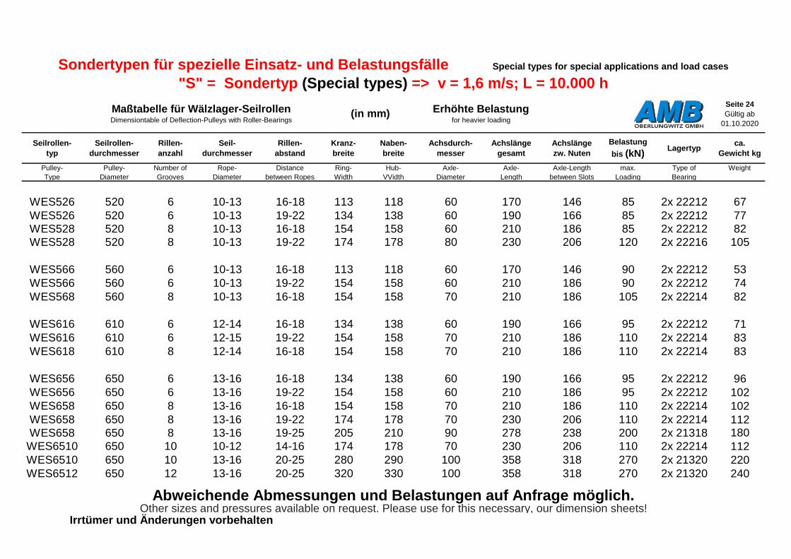
Seite 24
Gültig ab
01.10.2020
Seilrollen-
typ
Seilrollen-
durchmesser
Rillen-
anzahl
Seil-
durchmesser
Rillen-
abstand
Kranz-
breite
Naben-
breite
Achsdurch-
messer
Achslänge
gesamt
Achslänge
zw. Nuten
Belastung
bis (kN)Lagertyp
ca.
Gewicht kg
Pulley-
Type
Pulley-
Diameter
Number of
Grooves
Rope-
Diameter
Distance
between Ropes
Ring-
Width
Hub-
VVidth
Axle-
Diameter
Axle-
Length
Axle-Length
between Slots
max.
Loading
Type of
Bearing
Weight
WES526 520 6 10-13 16-18 113 118 60 170 146 85 2x 22212 67
WES526 520 6 10-13 19-22 134 138 60 190 166 85 2x 22212 77
WES528 520 8 10-13 16-18 154 158 60 210 186 85 2x 22212 82
WES528 520 8 10-13 19-22 174 178 80 230 206 120 2x 22216 105
WES566 560 6 10-13 16-18 113 118 60 170 146 90 2x 22212 53
WES566 560 6 10-13 19-22 154 158 60 210 186 90 2x 22212 74
WES568 560 8 10-13 16-18 154 158 70 210 186 105 2x 22214 82
WES616 610 6 12-14 16-18 134 138 60 190 166 95 2x 22212 71
WES616 610 6 12-15 19-22 154 158 70 210 186 110 2x 22214 83
WES618 610 8 12-14 16-18 154 158 70 210 186 110 2x 22214 83
WES656 650 6 13-16 16-18 134 138 60 190 166 95 2x 22212 96
WES656 650 6 13-16 19-22 154 158 60 210 186 95 2x 22212 102
WES658 650 8 13-16 16-18 154 158 70 210 186 110 2x 22214 102
WES658 650 8 13-16 19-22 174 178 70 230 206 110 2x 22214 112WES658 650 8 13-16 19-25 205 210 90 278 238 200 2x 21318 180
WES6510 650 10 10-12 14-16 174 178 70 230 206 110 2x 22214 112
WES6510 650 10 13-16 20-25 280 290 100 358 318 270 2x 21320 220
WES6512 650 12 13-16 20-25 320 330 100 358 318 270 2x 21320 240
Abweichende Abmessungen und Belastungen auf Anfrage möglich.
Irrtümer und Änderungen vorbehaltenOther sizes and pressures available on request. Please use for this necessary, our dimension sheets!
Maßtabelle für Wälzlager-SeilrollenDimensiontable of Deflection-Pulleys with Roller-Bearings
(in mm) Erhöhte Belastungfor heavier loading
Sondertypen für spezielle Einsatz- und Belastungsfälle Special types for special applications and load cases
"S" = Sondertyp (Special types) => v = 1,6 m/s; L = 10.000 h
Durchmesser-
bereich
P
max.
Kranzbreite
A
max.
Nabenbreite
V
Durchmesser-
bereich
P
max.
Kranzbreite
A
max.
Nabenbreite
V
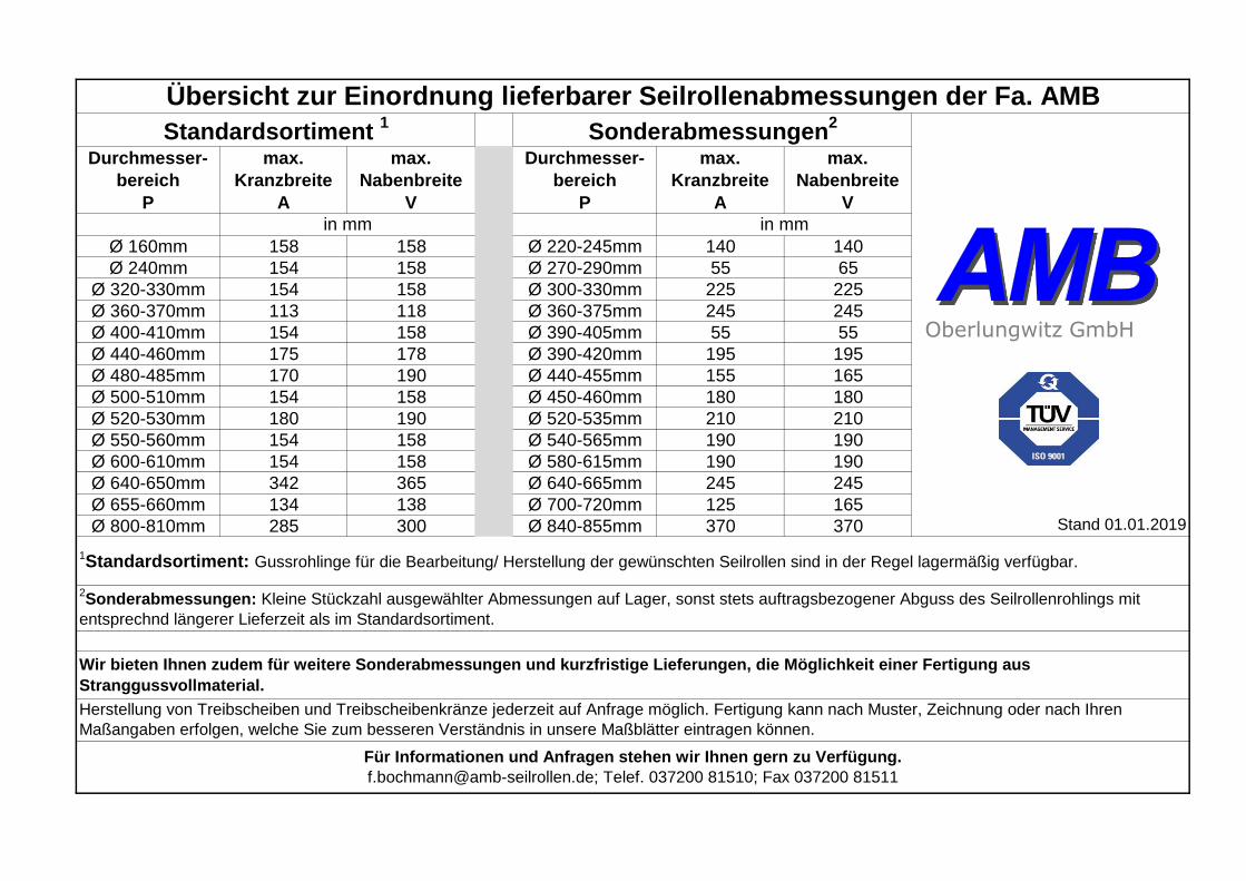
Ø 160mm 158 158 Ø 220-245mm 140 140
Ø 240mm 154 158 Ø 270-290mm 55 65
Ø 320-330mm 154 158 Ø 300-330mm 225 225
Ø 360-370mm 113 118 Ø 360-375mm 245 245
Ø 400-410mm 154 158 Ø 390-405mm 55 55
Ø 440-460mm 175 178 Ø 390-420mm 195 195
Ø 480-485mm 170 190 Ø 440-455mm 155 165
Ø 500-510mm 154 158 Ø 450-460mm 180 180
Ø 520-530mm 180 190 Ø 520-535mm 210 210
Ø 550-560mm 154 158 Ø 540-565mm 190 190
Ø 600-610mm 154 158 Ø 580-615mm 190 190
Ø 640-650mm 342 365 Ø 640-665mm 245 245
Ø 655-660mm 134 138 Ø 700-720mm 125 165
Ø 800-810mm 285 300 Ø 840-855mm 370 370
Herstellung von Treibscheiben und Treibscheibenkränze jederzeit auf Anfrage möglich. Fertigung kann nach Muster, Zeichnung oder nach Ihren
Maßangaben erfolgen, welche Sie zum besseren Verständnis in unsere Maßblätter eintragen können.
Für Informationen und Anfragen stehen wir Ihnen gern zu Verfügung.
[email protected]; Telef. 037200 81510; Fax 037200 81511
Übersicht zur Einordnung lieferbarer Seilrollenabmessungen der Fa. AMB
in mm in mm
Standardsortiment 1
Sonderabmessungen2
Stand 01.01.2019
1Standardsortiment: Gussrohlinge für die Bearbeitung/ Herstellung der gewünschten Seilrollen sind in der Regel lagermäßig verfügbar.
2Sonderabmessungen: Kleine Stückzahl ausgewählter Abmessungen auf Lager, sonst stets auftragsbezogener Abguss des Seilrollenrohlings mit
entsprechnd längerer Lieferzeit als im Standardsortiment.
Wir bieten Ihnen zudem für weitere Sonderabmessungen und kurzfristige Lieferungen, die Möglichkeit einer Fertigung aus
Stranggussvollmaterial.
Oberlungwitz GmbH
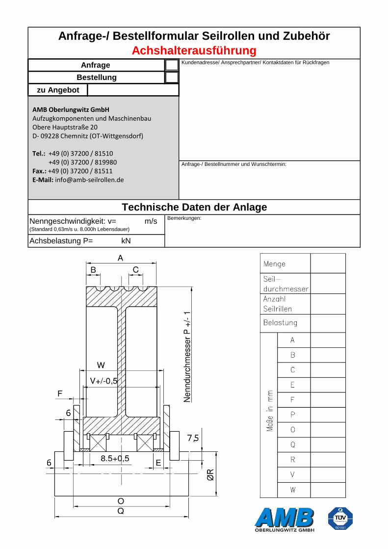
zu Angebot
Anfrage-/ Bestellnummer und Wunschtermin:
Technische Daten der Anlage Bemerkungen:
Anfrage-/ Bestellformular Seilrollen und Zubehör
Achshalterausführung Kundenadresse/ Ansprechpartner/ Kontaktdaten für RückfragenAnfrage
Bestellung
Nenngeschwindigkeit: v= m/s(Standard 0,63m/s u. 8.000h Lebensdauer)
Achsbelastung P= kN
AMB Oberlungwitz GmbH Aufzugkomponenten und Maschinenbau Obere Hauptstraße 20 D- 09228 Chemnitz (OT-Wittgensdorf) Tel.: +49 (0) 37200 / 81510 +49 (0) 37200 / 819980 Fax.: +49 (0) 37200 / 81511 E-Mail: [email protected]

zu Angebot
Anfrage-/ Bestellnummer und Wunschtermin:
Technische Daten der Anlage Bemerkungen:
Anfrage-/ Bestellformular Seilrollen und Zubehör
Lagerbockausführung Kundenadresse/ Ansprechpartner/ Kontaktdaten für RückfragenAnfrage
Bestellung
Nenngeschwindigkeit: v= m/s(Standard 0,63m/s u. 8.000h Lebensdauer)
Achsbelastung P= kN
AMB Oberlungwitz GmbH Aufzugkomponenten und Maschinenbau Obere Hauptstraße 20 D- 09228 Chemnitz (OT-Wittgensdorf) Tel.: +49 (0) 37200 / 81510 +49 (0) 37200 / 819980 Fax.: +49 (0) 37200 / 81511 E-Mail: [email protected]

28

zu Angebot
Anfrage-/ Bestellnummer und Wunschtermin:
Technische Daten der Anlage Bemerkungen:
Anfrage-/ Bestellformular Seilrollen und Zubehör
Gleitlagerausführung Kundenadresse/ Ansprechpartner/ Kontaktdaten für RückfragenAnfrage
Bestellung
Nenngeschwindigkeit: v= m/s(Standard 0,63m/s u. 8.000h Lebensdauer)
Achsbelastung P= kN
AMB Oberlungwitz GmbH Aufzugkomponenten und Maschinenbau Obere Hauptstraße 20 D- 09228 Chemnitz (OT-Wittgensdorf) Tel.: +49 (0) 37200 / 81510 +49 (0) 37200 / 819980 Fax.: +49 (0) 37200 / 81511 E-Mail: [email protected]

zu Angebot
Anfrage-/ Bestellnummer und Wunschtermin:
Technische Daten der Anlage Bemerkungen:
Anfrage-/ Bestellformular Treibscheiben und Zubehör
einteilig Kundenadresse/ Ansprechpartner/ Kontaktdaten für RückfragenAnfrage
Bestellung
Nenngeschwindigkeit: v= m/s(Standard 0,63m/s u. 8.000h Lebensdauer)
Achsbelastung P= kN
AMB Oberlungwitz GmbH Aufzugkomponenten und Maschinenbau Obere Hauptstraße 20 D- 09228 Chemnitz (OT-Wittgensdorf) Tel.: +49 (0) 37200 / 81510 +49 (0) 37200 / 819980 Fax.: +49 (0) 37200 / 81511 E-Mail: [email protected]

zu Angebot
Anfrage-/ Bestellnummer und Wunschtermin:
Technische Daten der Anlage Bemerkungen:
Anfrage-/ Bestellformular Treibscheiben und Zubehör
einteilig, kegelige Bohrung Kundenadresse/ Ansprechpartner/ Kontaktdaten für RückfragenAnfrage
Bestellung
Nenngeschwindigkeit: v= m/s(Standard 0,63m/s u. 8.000h Lebensdauer)
Achsbelastung P= kN
AMB Oberlungwitz GmbH Aufzugkomponenten und Maschinenbau Obere Hauptstraße 20 D- 09228 Chemnitz (OT-Wittgensdorf) Tel.: +49 (0) 37200 / 81510 +49 (0) 37200 / 819980 Fax.: +49 (0) 37200 / 81511 E-Mail: [email protected]

Ø50

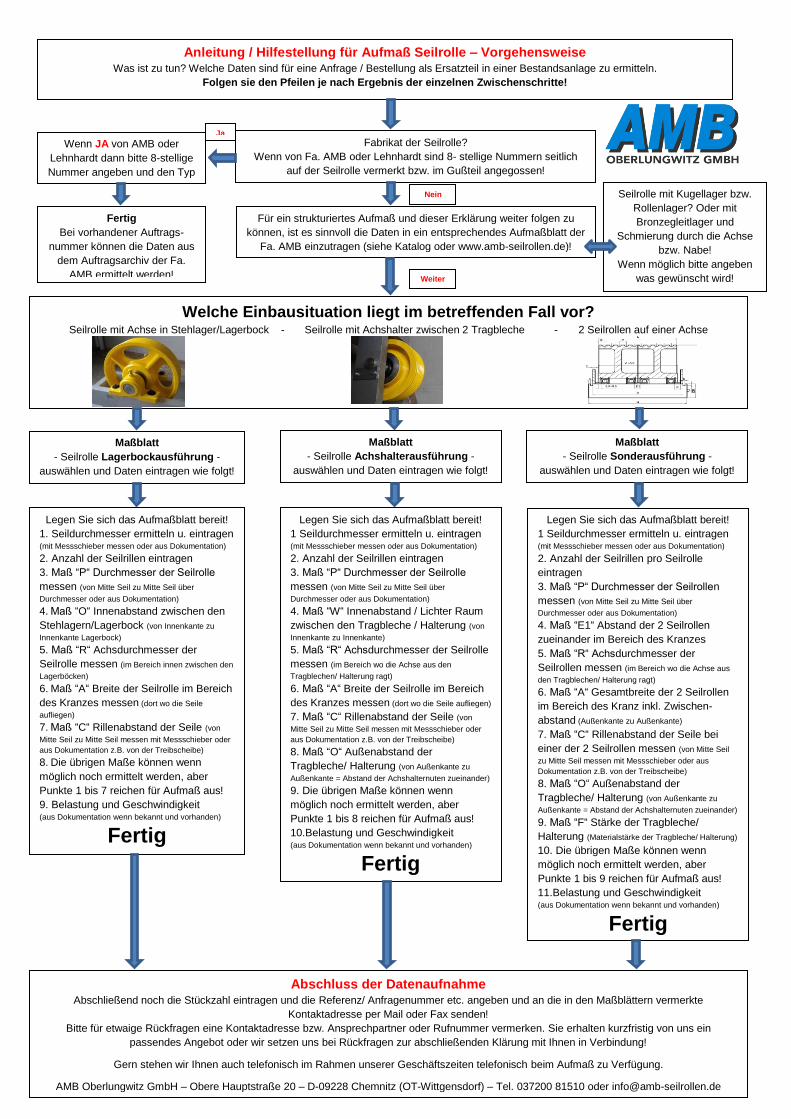
Anleitung / Hilfestellung für Aufmaß Seilrolle – Vorgehensweise Was ist zu tun? Welche Daten sind für eine Anfrage / Bestellung als Ersatzteil in einer Bestandsanlage zu ermitteln.
Folgen sie den Pfeilen je nach Ergebnis der einzelnen Zwischenschritte!
Fabrikat der Seilrolle?
Wenn von Fa. AMB oder Lehnhardt sind 8- stellige Nummern seitlich
auf der Seilrolle vermerkt bzw. im Gußteil angegossen!
Wenn JA von AMB oder
Lehnhardt dann bitte 8-stellige
Nummer angeben und den Typ
Nummern seitlich der Seilrolle
vermerkt mit bzw. im Gußteil
angegossen! Fertig
Bei vorhandener Auftrags-
nummer können die Daten aus
dem Auftragsarchiv der Fa.
AMB ermittelt werden!
Für ein strukturiertes Aufmaß und dieser Erklärung weiter folgen zu
können, ist es sinnvoll die Daten in ein entsprechendes Aufmaßblatt der
Fa. AMB einzutragen (siehe Katalog oder www.amb-seilrollen.de)!
Ja
Nein
Welche Einbausituation liegt im betreffenden Fall vor? Seilrolle mit Achse in Stehlager/Lagerbock - Seilrolle mit Achshalter zwischen 2 Tragbleche - 2 Seilrollen auf einer Achse
Weiter
Seilrolle mit Kugellager bzw.
Rollenlager? Oder mit
Bronzegleitlager und
Schmierung durch die Achse
bzw. Nabe!
Wenn möglich bitte angeben
was gewünscht wird!
Maßblatt
- Seilrolle Lagerbockausführung -
auswählen und Daten eintragen wie folgt!
Maßblatt
- Seilrolle Achshalterausführung -
auswählen und Daten eintragen wie folgt!
Maßblatt
- Seilrolle Sonderausführung -
auswählen und Daten eintragen wie folgt!
Legen Sie sich das Aufmaßblatt bereit!
1. Seildurchmesser ermitteln u. eintragen (mit Messschieber messen oder aus Dokumentation)
2. Anzahl der Seilrillen eintragen
3. Maß “P“ Durchmesser der Seilrolle
messen (von Mitte Seil zu Mitte Seil über
Durchmesser oder aus Dokumentation)
4. Maß “O“ Innenabstand zwischen den
Stehlagern/Lagerbock (von Innenkante zu
Innenkante Lagerbock)
5. Maß “R“ Achsdurchmesser der
Seilrolle messen (im Bereich innen zwischen den
Lagerböcken)
6. Maß “A“ Breite der Seilrolle im Bereich
des Kranzes messen (dort wo die Seile
aufliegen)
7. Maß “C“ Rillenabstand der Seile (von
Mitte Seil zu Mitte Seil messen mit Messschieber oder
aus Dokumentation z.B. von der Treibscheibe)
8. Die übrigen Maße können wenn
möglich noch ermittelt werden, aber
Punkte 1 bis 7 reichen für Aufmaß aus!
9. Belastung und Geschwindigkeit (aus Dokumentation wenn bekannt und vorhanden)
Fertig
Legen Sie sich das Aufmaßblatt bereit!
1 Seildurchmesser ermitteln u. eintragen (mit Messschieber messen oder aus Dokumentation)
2. Anzahl der Seilrillen eintragen
3. Maß “P“ Durchmesser der Seilrolle
messen (von Mitte Seil zu Mitte Seil über
Durchmesser oder aus Dokumentation)
4. Maß “W“ Innenabstand / Lichter Raum
zwischen den Tragbleche / Halterung (von
Innenkante zu Innenkante)
5. Maß “R“ Achsdurchmesser der Seilrolle
messen (im Bereich wo die Achse aus den
Tragblechen/ Halterung ragt)
6. Maß “A“ Breite der Seilrolle im Bereich
des Kranzes messen (dort wo die Seile aufliegen)
7. Maß “C“ Rillenabstand der Seile (von
Mitte Seil zu Mitte Seil messen mit Messschieber oder
aus Dokumentation z.B. von der Treibscheibe)
8. Maß “O“ Außenabstand der
Tragbleche/ Halterung (von Außenkante zu
Außenkante = Abstand der Achshalternuten zueinander)
9. Die übrigen Maße können wenn
möglich noch ermittelt werden, aber
Punkte 1 bis 8 reichen für Aufmaß aus!
10.Belastung und Geschwindigkeit (aus Dokumentation wenn bekannt und vorhanden)
Fertig
Legen Sie sich das Aufmaßblatt bereit!
1 Seildurchmesser ermitteln u. eintragen (mit Messschieber messen oder aus Dokumentation)
2. Anzahl der Seilrillen pro Seilrolle
eintragen
3. Maß “P“ Durchmesser der Seilrollen
messen (von Mitte Seil zu Mitte Seil über
Durchmesser oder aus Dokumentation)
4. Maß “E1“ Abstand der 2 Seilrollen
zueinander im Bereich des Kranzes
5. Maß “R“ Achsdurchmesser der
Seilrollen messen (im Bereich wo die Achse aus
den Tragblechen/ Halterung ragt)
6. Maß “A“ Gesamtbreite der 2 Seilrollen
im Bereich des Kranz inkl. Zwischen-
abstand (Außenkante zu Außenkante)
7. Maß “C“ Rillenabstand der Seile bei
einer der 2 Seilrollen messen (von Mitte Seil
zu Mitte Seil messen mit Messschieber oder aus
Dokumentation z.B. von der Treibscheibe)
8. Maß “O“ Außenabstand der
Tragbleche/ Halterung (von Außenkante zu
Außenkante = Abstand der Achshalternuten zueinander)
9. Maß “F“ Stärke der Tragbleche/
Halterung (Materialstärke der Tragbleche/ Halterung)
10. Die übrigen Maße können wenn
möglich noch ermittelt werden, aber
Punkte 1 bis 9 reichen für Aufmaß aus!
11.Belastung und Geschwindigkeit (aus Dokumentation wenn bekannt und vorhanden)
Fertig
Abschluss der Datenaufnahme Abschließend noch die Stückzahl eintragen und die Referenz/ Anfragenummer etc. angeben und an die in den Maßblättern vermerkte
Kontaktadresse per Mail oder Fax senden!
Bitte für etwaige Rückfragen eine Kontaktadresse bzw. Ansprechpartner oder Rufnummer vermerken. Sie erhalten kurzfristig von uns ein
passendes Angebot oder wir setzen uns bei Rückfragen zur abschließenden Klärung mit Ihnen in Verbindung!
Gern stehen wir Ihnen auch telefonisch im Rahmen unserer Geschäftszeiten telefonisch beim Aufmaß zu Verfügung.
AMB Oberlungwitz GmbH – Obere Hauptstraße 20 – D-09228 Chemnitz (OT-Wittgensdorf) – Tel. 037200 81510 oder [email protected]

Antwort - Fax
Unsere Fax-Nummer: 037200 81511
An: Von:
AMB Oberlungwitz GmbH
Aufzugskomponenten und Maschinenbau
Obere Hauptstraße 20
D-09228 Chemnitz OT Wittgensdorf
Tel.: 0049 (0)37200 81510
Wir nehmen Bezug auf Ihre Firmenofferte:
Bitte senden Sie uns mehr Informationsmaterial
Wir bitten um eine persönliche Beratung
Wir bitten um telefonischen Rückruf
Bitte unterbreiten Sie uns ein konkretes Angebot*
* Wenn möglich, verwenden Sie die beiliegenden Maßblätter, damit eine optimale Bearbeitung möglich ist.
… oder besuchen Sie uns doch ganz einfach im Internet
www.amb-seilrollen.de

@
AMB Oberlungwitz GmbH
Aufzugskomponenten und
Maschinenbau
Obere Hauptstraße 20
D-09228 Chemnitz OT Wittgensdorf
(037200) 8 15 10
(037200) 8 15 11
www.amb-seilrollen.de
4
72 AMB Oberlungwitz GmbH


