
Kurzbeschreibung
Brief description
Steuerung ControllerCECC-X-M1-MV
– Deutsch– English
80407621511NH[8040763]
Steuerung CECC

Festo CECC-X-M1-MV 1511NH 2
Deutsch 3. . . . . . . . . . . . . . . . . . . . . . . . . . . . . . . . . . . . . . . . . . .
CANopen®, CODESYS®, EtherCAT®, EtherNet/IP®, IO-Link®, undMODBUS® sind eingetragene Warenzeichen der jeweiligen Markeninhaber in gewissen Ländern.
Dieses Produkt verwendet Opensource Software, welche der “GNUGeneral Public License, Version 2” unterliegt. Die Lizenzbedingungen der GPL sind im Engineering Tool bzw. unter folgenderAdresse verfügbar: http://www.gnu.org/copyleft/gpl.html
English 29. . . . . . . . . . . . . . . . . . . . . . . . . . . . . . . . . . . . . . . . . . . .
CANopen®, CODESYS®, EtherCAT®, EtherNet/IP®, IO-Link®, andMODBUS® are registered trademarks of their respective trademarkholders in certain countries.
This product uses opensource software which is subject to the“GNU General Public License, Version 2”. The licensing conditionsof the GPL are located either in the product’s engineering tool or atthe following address: http://www.gnu.org/copyleft/gpl.html
Edition: 1511NHOriginal: de
© (Festo AG & Co. KG, 73726 Esslingen, Germany, 2015)Internet: �http://www.festo.comE-Mail: �[email protected]
Festo CECC-X-M1-MV 1511NH Deutsch 3
Deutsch1 Sicherheit
1.1 Allgemeine Sicherheitshinweise
� Die Sicherheitshinweise in den entsprechenden Kapiteln beachten.
Die speziellen Sicherheitsvorschriften stehen direkt vor derHandlungsanweisung.
Warnung
Elektrische SpannungVerletzung durch Stromschlag, Schäden an Maschine und Anlage.Gefahr eines elektrischen Schlags bei Spannungsquellen.Vor Montage, Installations und/oder Wartungsarbeiten:� Versorgungsspannung abschalten und gegen unbeabsichtigtes
Wiedereinschalten sichern.� Ausschließlich Stromquellen verwenden, die eine sichere
elektrische Trennung der Betriebsspannung nachIEC�602041/EN�602041 gewährleisten.
� Spannungen erst nach Abschluss der Arbeiten wieder einschalten.
Hinweis
Unberechtigte Zugriffe auf das Produkt können Schäden oder Fehlfunktionen verursachen.Beim Anschluss des Produkts an ein Netzwerk:� Netzwerk vor unberechtigten Zugriffen schützen.Maßnahmen zum Schutz des Netzwerks sind z. B.: Firewall, IntrusionPrevention System (IPS), Netzwerk-Segmentierung, Virtuelles LAN(VLAN), Virtual Private Network (VPN), Sicherheit auf physikalischerZugangsebene (Port Security).Weitere Hinweise � Richtlinien und Normen zur Sicherheit in derInformationstechnik, z.�B.�IEC 62443, ISO/IEC 27001. Ein Zugangskennwort schützt ausschließlich gegen versehentliches Ändern.
Festo CECC-X-M1-MV 1511NH Deutsch4
1.2 Bestimmungsgemäße Verwendung
Die in dieser Kurzbeschreibung dokumentierte Steuerung ist ausschließlich zum Einbau in eine Maschine oder eine automatisierungstechnischeAnlage bestimmt.
Das Produkt ist nur folgendermaßen zu benutzen:– bestimmungsgemäß im Industriebereich– zum Einbau in einen Schaltschrank
� Das Produkt nur im Originalzustand ohne eigenmächtige Veränderungverwenden.
� Die zulässigen Grenzwerte und Spezifikationen einhalten��13�Technische Daten.
� Das Produkt nur in technisch einwandfreiem Zustand verwenden.
HinweisBei Schäden, die durch unbefugte Eingriffe oder nicht bestimmungsgemäßer Verwendung entstehen, erlischt derGewährleistungs- und Haftungsanspruch gegenüber demHersteller.

Festo CECC-X-M1-MV 1511NH Deutsch 5
2 Voraussetzungen für den Produkteinsatz
� Stellen Sie diese Kurzbeschreibung dem Konstrukteur, Monteur unddem für die Inbetriebnahme zuständigen Personal der Maschine oderAnlage, an der diese Produkte zum Einsatz kommen, zur Verfügung.
� Stellen Sie sicher, dass die Vorgaben der Dokumentation stets eingehalten werden. Berücksichtigen Sie hierbei auch die Dokumentationenzu weiteren Komponenten und Modulen ��13�Technische Daten.
� Berücksichtigen Sie für den Bestimmungsort geltenden gesetzlichenRegelungen sowie:– Vorschriften und Normen– Regelungen der Prüforganisationen und Versicherungen– nationale Bestimmungen
2.1 Qualifikation des Fachpersonals
Folgende Arbeitsschritte dürfen nur von qualifiziertem Fachpersonalvorgenommen werden:– Einbau– Installation– Inbetriebnahme– Pflege– Reparatur
Das Fachpersonal muss vertraut sein mit:– elektrischer Steuerungstechnik– den geltenden Vorschriften zum Betrieb sicherheitstechnischer
Anlagen– den geltenden Vorschriften zur Unfallverhütung und Arbeitssicherheit
Festo CECC-X-M1-MV 1511NH Deutsch6
3 Lieferumfang
– Steuerung CECC-X-M1-MV– Diese Kurzbeschreibung
Software für das Produkt finden Sie im Support-Portal vonFesto���www.festo.com/sp.
4 Zubehör
– Kamera– Steckersortiment
Katalog ��www.festo.com/sp
Bitte wenden Sie sich bei Fragen zur Technik und zum Zubehör an Ihrenregionalen Ansprechpartner von Festo.
Festo CECC-X-M1-MV 1511NH Deutsch 7
5 Übersicht
aF
aD
aE
4
1
2
3
5 6 7 8 aJ aA
aB
aC
9
aH aG
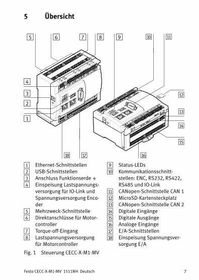
1 Ethernet-Schnittstellen2 USB-Schnittstellen3 Anschluss Funktionserde��4 Einspeisung Lastspannungs
versorgung für IO-Link undSpannungsversorgung Encoder
5 Mehrzweck-Schnittstelle6 Direktanschlüsse für Motor
controller7 Torque-off-Eingang8 Lastspannungsversorgung
für�Motorcontroller
9 Status-LEDsaJ Kommunikationsschnitt
stellen: ENC, RS232, RS422,RS485 und IO-Link
aA CANopen-Schnittstelle CAN�1aB MicroSD-KartensteckplatzaC CANopen-Schnittstelle CAN�2aD Digitale EingängeaE Digitale AusgängeaF Analoge EingängeaG E/A-SchnittstellenaH Einspeisung Spannungsver
sorgung E/A
Fig. 1 Steuerung CECC-X-M1-MV

Festo CECC-X-M1-MV 1511NH Deutsch8
6 Installation
HinweisBeschädigung des Produkts durch unsachgemäße Handhabung.� Stecker und Schnittstellen nie unter Spannung abziehen
oder einstecken.� Handhabungsvorschriften für elektrostatisch gefährdete
Bauelemente beachten.
Das Produkt kann auf einer Hutschiene oder an einer ebenen Fläche inbeliebiger Einbaulage montiert werden.
� Genügend Raum freihalten:– oberhalb und unterhalb des Produkts für Anschlussleitungen– rechts des Produkts für Kaltlufteintritt und Zugang zum MicroSD-
Kartensteckplatz.
81mm
122,2 mm
bJ
aI
20mm
bA
aI Befestigungslasche
bA Abstand
bJ Montagebohrungen
Fig. 2
Festo CECC-X-M1-MV 1511NH Deutsch 9
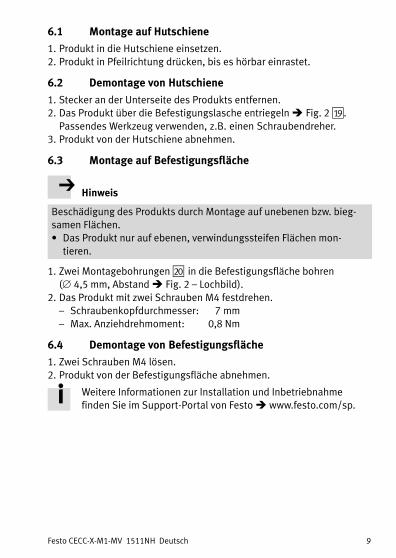
6.1 Montage auf Hutschiene
1. Produkt in die Hutschiene einsetzen.2. Produkt in Pfeilrichtung drücken, bis es hörbar einrastet.
6.2 Demontage von Hutschiene
1. Stecker an der Unterseite des Produkts entfernen.2. Das Produkt über die Befestigungslasche entriegeln ��Fig. 2�aI ��.
Passendes Werkzeug verwenden, z.�B. einen Schraubendreher.3. Produkt von der Hutschiene abnehmen.
6.3 Montage auf Befestigungsfläche
Hinweis
Beschädigung des Produkts durch Montage auf unebenen bzw. biegsamen Flächen.� Das Produkt nur auf ebenen, verwindungssteifen Flächen mon
tieren.
1. Zwei Montagebohrungen�bJ� in die Befestigungsfläche bohren(�4,5 mm, Abstand � Fig. 2 – Lochbild).
2. Das Produkt mit zwei Schrauben M4 festdrehen.– Schraubenkopfdurchmesser: 7�mm– Max. Anziehdrehmoment: 0,8 Nm
6.4 Demontage von Befestigungsfläche
1. Zwei Schrauben M4 lösen.2. Produkt von der Befestigungsfläche abnehmen.
Weitere Informationen zur Installation und Inbetriebnahmefinden Sie im Support-Portal von Festo � www.festo.com/sp.
Festo CECC-X-M1-MV 1511NH Deutsch10
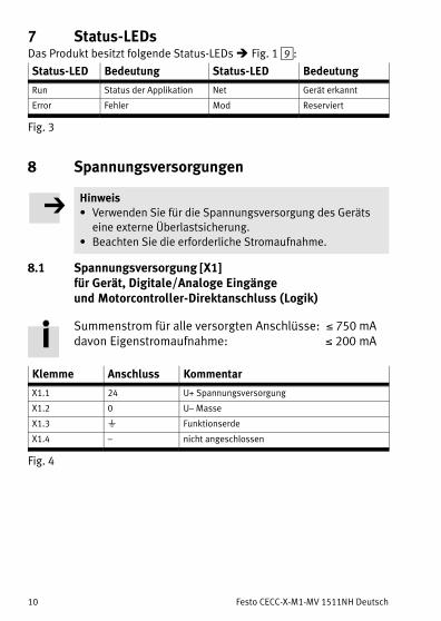
7 Status-LEDsDas Produkt besitzt folgende Status-LEDs ��Fig. 1 9:
Status-LED Bedeutung Status-LED Bedeutung
Run Status der Applikation Net Gerät erkannt
Error Fehler Mod Reserviert
Fig. 3
8 Spannungsversorgungen
Hinweis� Verwenden Sie für die Spannungsversorgung des Geräts
eine externe Überlastsicherung.� Beachten Sie die erforderliche Stromaufnahme.
8.1 Spannungsversorgung [X1]für Gerät, Digitale/Analoge Eingänge und Motorcontroller-Direktanschluss (Logik)
Summenstrom für alle versorgten Anschlüsse: 750 mAdavon Eigenstromaufnahme: �200�mA
Klemme Anschluss Kommentar
X1.1 24 U+ Spannungsversorgung
X1.2 0 U– Masse
X1.3 � Funktionserde
X1.4 – nicht angeschlossen
Fig. 4

Festo CECC-X-M1-MV 1511NH Deutsch 11
8.2 Spannungsversorgung [X5] für Digitale Ausgänge
Summenstrom für alle versorgten Anschlüsse: �5 A
Klemme Anschluss Kommentar
X5.1 24 U+ Spannungsversorgung
X5.2 0 U– Masse
Fig. 5
8.3 Lastspannungsversorgung [X21] für Motorcontroller
Summenstrom für alle versorgten Anschlüsse: �8 A
Klemme Kommentar
X21.1 24�V/48�V Einspeisung Lastspannungsversorgung
X21.2 GND
Fig. 6
Hinweis
Beschädigung des Produkts bei Überlast.Bei Belastung aller digitalen Ausgänge mit jeweils 0,5�A kann der Summenstrom überschritten werden, sobald weitere Verbraucher genutztwerden.� Berücksichtigen Sie alle Strombelastungen.� Wenden Sie sich bei besonderen Konfigurationen an den lokalen
Service von Festo.
Festo CECC-X-M1-MV 1511NH Deutsch12
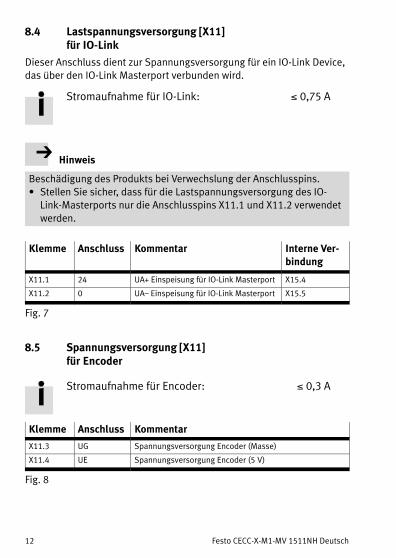
8.4 Lastspannungsversorgung [X11] für IO-Link
Dieser Anschluss dient zur Spannungsversorgung für ein IOLink Device,das über den IOLink Masterport verbunden wird.
Stromaufnahme für IO-Link: �0,75 A
Hinweis
Beschädigung des Produkts bei Verwechslung der Anschlusspins.� Stellen Sie sicher, dass für die Lastspannungsversorgung des IO-
Link-Masterports nur die Anschlusspins X11.1 und X11.2 verwendetwerden.
Klemme Anschluss Kommentar Interne Verbindung
X11.1 24 UA+ Einspeisung für IO-Link Masterport X15.4
X11.2 0 UA– Einspeisung für IO-Link Masterport X15.5
Fig. 7
8.5 Spannungsversorgung [X11] für Encoder
Stromaufnahme für Encoder: �0,3 A
Klemme Anschluss Kommentar
X11.3 UG Spannungsversorgung Encoder (Masse)
X11.4 UE Spannungsversorgung Encoder (5�V)
Fig. 8

Festo CECC-X-M1-MV 1511NH Deutsch 13
9 Schnittstellen vorne
[X6][X10][X8]
[X1]
[X9][X7]
[X11] [X12] [X13] [X14] [X15] [X16]
[X2] [X3] [X4] [X5]
Fig. 9
9.1 E/A-Schnittstelle [X2, X3, X4]
Klemme Kommentar
X2.0 … X2.1 2 schnelle digitale Eingänge (200 kHz)
X2.2 … X2.71),2) 6 digitale Eingänge (1 kHz, IEC�Typ�1)
X3.0 … X3.5 6 digitale Eingänge (1 kHz, IEC�Typ�1)
X4.0 … X4.73) 8 digitale Ausgänge (0,7�A pro Kanal, PNP, SSR4))
1) X2.2 und X2.3 dienen optional auch als MachineVision-Eingänge (z.�B. Trigger)
2) X2.3 dient auch als LatchEingang für den Encoder über die Mehrfachschnittstelle X14
3) X4.0 ... X4.2 dienen optional auch als MachineVision-Ausgänge (z.�B. Blitzausgang)
4) SSR: Solid State Relay
Fig. 10

Festo CECC-X-M1-MV 1511NH Deutsch14
9.2 CANopen-Schnittstelle CAN�1 [X6]
Pin Anschluss Kommentar
1 – nicht angeschlossen
2 CAN1_L1) CANBusSignal�1 (dominant low)
3 CAN_GND CAN Ground
4 – nicht angeschlossen
5 CAN_SHLD Verbindung zu Funktionserde
6 CAN_GND CAN Ground (optional)
7 CAN1_H1) CANBusSignal�1 (dominant high)
8 – nicht angeschlossen
9 – nicht angeschlossen
1) Bei Anschluss des Geräts am Leitungsende: Pin�2 und Pin�7 über Widerstand verbinden.
Einen passenden Stecker mit Widerstand (120 Ω/0,25 W) finden Sie im Zubehör von
Festo�� www.festo.com/catalogue
Fig. 11
9.3 USB-Schnittstellen [X7, X9]
Die USB-Schnittstellen � Fig. 1�2 � sind kompatibel mit den StandardsUSB�3.0 und USB�2.0. Sie sind für USB-Stecker Typ A geeignet.Folgende Funktionen werden unterstützt (Leitungslänge� 3�m):– Übertragung von Boot-Projekten– Generelle Datenspeicherung– Anschluss einer Kamera– Anschluss von Hardware-Erweiterungen
Hinweis
Beschädigung des Produkts.� Ausschließlich USB-Komponenten mit einem Stromver
brauch��0,9 A verwenden.
Bitte wenden Sie sich bei Fragen zu Erweiterungen an Ihren regionalenAnsprechpartner von Festo.
Festo CECC-X-M1-MV 1511NH Deutsch 15
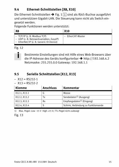
9.4 Ethernet-Schnittstellen [X8, X10]
Die Ethernet-Schnittstellen � Fig. 1�1 � sind als RJ45-Buchse ausgeführtund unterstützen Gigabit-LAN. Die Steuerung kann nicht als Switch eingesetzt werden.Folgende Funktionen werden unterstützt:
X8 X10
– TCP/IP (z.�B. Modbus TCP)– UDP (z.�B. Netzwerkvariablen, EasyIP)– EtherNet/IP (z.�B. Generic IODevice)
– EtherCATMaster
Fig. 12
Bestimmte Einstellungen sind mit Hilfe eines WebBrowsers überdie IP-Adresse des Geräts konfigurierbar���http://192.168.4.2Netzmaske: 255.255.0.0 Gateway:�192.168.1.1
9.5 Serielle Schnittstellen [X12, X13]
– X12 = RS232-1– X13 = RS232-2
Klemme Anschluss Kommentar
X12.1, X13.1 G Masse
X12.2, X13.2 Tx Sendedaten1) (Ausgang)
X12.3, X13.3 Rx Empfangsdaten1) (Eingang)
X12.4, X13.4 S Schirm, Verbindung zu Funktionserde
1) Max. Pegel: Low –15�V High +15�V; TTLPegel nicht zulässig!
Fig. 13
Festo CECC-X-M1-MV 1511NH Deutsch16
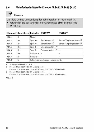
9.6 Mehrfachschnittstelle Encoder/RS422/RS485 [X14]
Hinweis
Die gleichzeitige Verwendung der Schnittstellen ist nicht möglich.� Verwenden Sie ausschließlich die Anschlüsse einer Schnittstelle
��Fig. 14.
Klemme Anschluss Encoder RS4221) RS4851)
X14.1 G Masse
X14.2 A+ Spur A�+ Sendedaten�+2) Sende-/Empfangsdaten�+2)
X14.3 A– Spur A�– Sendedaten�–2) Sende-/Empfangsdaten�–2)
X14.4 B+ Spur B�+ Empfangsdaten�+ 3) –
X14.5 B– Spur B�– Empfangsdaten�– 3) –
X14.6 N+ Nullspur�+ – –
X14.7 N– Nullspur�–� – –
X14.8 S Schirm, Verbindung zu Funktionserde
1) Zulässige Datenrate �1�MHz
2) Bei Anschluss des Geräts am Leitungsende:
Klemmen X14.2 und X14.3 über Widerstand�(120 Ω/0,25 W) verbinden.
3) Bei Anschluss des Geräts am Leitungsende:
Klemmen X14.4 und X14.5 über Widerstand�(120 Ω/0,25 W) verbinden.
Fig. 14
Festo CECC-X-M1-MV 1511NH Deutsch 17
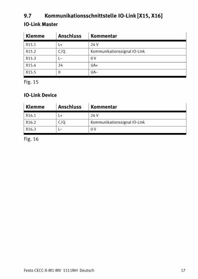
9.7 Kommunikationsschnittstelle IO-Link [X15, X16]
IO-Link Master
Klemme Anschluss Kommentar
X15.1 L+ 24 V
X15.2 C/Q Kommunikationssignal IO-Link
X15.3 L– 0 V
X15.4 24 UA+
X15.5 0 UA–
Fig. 15
IO-Link Device
Klemme Anschluss Kommentar
X16.1 L+ 24 V
X16.2 C/Q Kommunikationssignal IO-Link
X16.3 L– 0 V
Fig. 16

Festo CECC-X-M1-MV 1511NH Deutsch18
10 Direktanschlüsse oben
[X21] [X24]
[X25] [X28]
[X23] Antrieb�B[X22] Antrieb�A
[X27] Antrieb�D[X26] Antrieb�C
1 2 3 4 5 6 7 8 9 10
1 2 3 4 5 6 7 8 9 10
1 2 3 4 5 6 7 8 9 10
1 2 3 4 5 6 7 8 9 10
1 2 3
1 2 3
1 2
1 2
Fig. 17
10.1 Motorcontroller A, B, C, D [X22,�X23,�X26,�X27]mit CANopen-Schnittstelle�CAN�2
Summenstrom für alle Anschlüsse: �8 ALeitungslänge: �3�m
Klemme Anschluss Kommentar Interne Verbindung
X2x.1 24/48�VDC Lastspannungsversorgung Motor
controller1)X21.1
X2x.2 GND X21.2
X2x.3 24�VDC Spannungsversorgung Motorcon
troller (Logik)X1.1
X2x.4 GND X1.2
X2x.5 CAN2_H CANBusSignal�2 (dominant�high) X18.1
X2x.6 CAN2_L CANBusSignal�2 (dominant�low) X18.2
X2x.7 CAN_GND CAN Ground X18.3
X2x.8 CAN_SHLD Verbindung zu Funktionserde X18.4
1) Dauerlast pro Ausgang: �2,0�A
Impulsstrom pro Ausgang: �4,2�A

Festo CECC-X-M1-MV 1511NH Deutsch 19
Klemme Anschluss Kommentar Interne Verbindung
X2x.9 GPIO Home-Signal (Digital In) X17.0.2/X17.1.2 2)
Mehrzweck-Signal X24.2/X28.2 3)
X2x.10 GND Spannungsversorgung (Logik) X1.2
2) Home-Signal: X22.9 (Antrieb�A) an X17.0.2; X26.9 (Antrieb�C) an X17.1.2
3) Mehrzweck-Signal: X23.9 (Antrieb�B) an X24.2; X27.9 (Antrieb�D) an X28.2
Fig. 18
10.2 Mehrzweck-Schnittstelle [X24, X28]
Klemme Anschluss Kommentar
X2x.1 24�VDC Spannungsversorgung
X2x.2 Signal Mehrzweck-Signal
X2x.3 GND Masse
Fig. 19
10.3 Torque-off-Eingang [X25]
Klemme Anschluss Kommentar
X25.1 Signal Torque-Off-Eingang
X25.2 24�VDC Spannungsversorgung
Fig. 20
Lastspannungsversorgung [X21]���8.3.
Festo CECC-X-M1-MV 1511NH Deutsch20
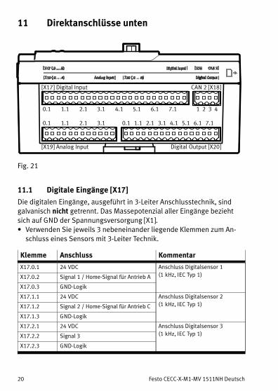
11 Direktanschlüsse unten
[X19] Analog Input Digital Output [X20]
[X17] Digital Input CAN 2 [X18]
0.1 1.1 2.1 3.1 4.1 5.1 6.1 7.1 1 2 3 4
0.1 1.1 3.12.1 0.1 1.1 2.1 3.1 4.1 5.1 6.1 7.1
Fig. 21
11.1 Digitale Eingänge�[X17]
Die digitalen Eingänge, ausgeführt in 3-Leiter Anschlusstechnik, sindgalvanisch nicht getrennt. Das Massepotenzial aller Eingänge beziehtsich auf GND der Spannungsversorgung [X1].� Verwenden Sie jeweils 3 nebeneinander liegende Klemmen zum An
schluss eines Sensors mit 3-Leiter Technik.
Klemme Anschluss Kommentar
X17.0.1 24�VDC Anschluss Digitalsensor�1
(1�kHz, IEC�Typ�1)X17.0.2 Signal�1 / Home-Signal für Antrieb A
X17.0.3 GND-Logik
X17.1.1 24�VDC Anschluss Digitalsensor�2
(1�kHz, IEC�Typ�1)X17.1.2 Signal�2 / Home-Signal für Antrieb C
X17.1.3 GND-Logik
X17.2.1 24�VDC Anschluss Digitalsensor�3
(1�kHz, IEC�Typ�1)X17.2.2 Signal 3
X17.2.3 GND-Logik

Festo CECC-X-M1-MV 1511NH Deutsch 21
Klemme KommentarAnschluss
X17.3.1 24�VDC Anschluss Digitalsensor�4
(1�kHz, IEC�Typ�1)X17.3.2 Signal 4
X17.3.3 GND-Logik
X17.4.1 24�VDC Anschluss Digitalsensor�5
(1�kHz, IEC�Typ�1)X17.4.2 Signal 5
X17.4.3 GND-Logik
X17.5.1 24�VDC Anschluss Digitalsensor�6
(1�kHz, IEC�Typ�1)X17.5.2 Signal 6
X17.5.3 GND-Logik
X17.6.1 24�VDC Anschluss Digitalsensor�7
(1�kHz, IEC�Typ�1)X17.6.2 Signal 7
X17.6.3 GND-Logik
X17.7.1 24�VDC Anschluss Digitalsensor�8
(1�kHz, IEC�Typ�1)X17.7.2 Signal 8
X17.7.3 GND-Logik
Fig. 22
Die Eingänge sind einstellbar für PNP- oder NPN-Sensoren.Die Konfiguration erfolgt via Codesys-Parameter im Steuerungsprojekt für alle Eingänge gemeinsam.
11.2 CANopen-Schnittstelle CAN�2 [X18]
Klemme Anschluss Kommentar
X18.1 CAN2_H1) CANBusSignal�2 (dominant high)
X18.2 CAN2_L1) CANBusSignal�2 (dominant low)
X18.3 CAN_GND CAN Ground
X18.4 CAN_SHLD Verbindung zu Funktionserde
1) Kein Abschlusswiderstand erforderlich, Anschlüsse sind intern über Widerstand verbunden.
Fig. 23

Festo CECC-X-M1-MV 1511NH Deutsch22
11.3 Analoge Eingänge [X19]
Die analogen Eingänge, ausgeführt in 3-Leiter Anschlusstechnik, sindgalvanisch nicht getrennt. Das Massepotenzial aller Eingänge beziehtsich auf GND der Spannungsversorgung [X1].Ein eingehendes Signal wird mit einer Auflösung von 14�Bit digitalisiert.
Klemme Anschluss Kommentar
X19.0.1 24�VDC Anschluss Analogsensor 1
(0 ... 10�V; 0 ... 20�mA)X19.0.2 Signal
X19.0.3 GND
X19.1.1 24�VDC Anschluss Analogsensor 2
(0 ... 10�V; 0 ... 20�mA)X19.1.2 Signal
X19.1.3 GND
X19.2.1 24�VDC Anschluss Analogsensor 3
(0 ... 10�V; 0 ... 20�mA)X19.2.2 Signal
X19.2.3 GND
X19.3.1 24�VDC Anschluss Analogsensor 4
(0 ... 10�V; 0 ... 20�mA)X19.3.2 Signal
X19.3.3 GND
Fig. 24
Die Eingänge können wahlweise mit Spannungssignal (0�... 10�V)oder Stromsignal (0�... 20�mA) betrieben werden.Die Konfiguration erfolgt über Codesys-Parameter im Steuerungsprojekt für jeden Eingang getrennt.

Festo CECC-X-M1-MV 1511NH Deutsch 23
11.4 Digitale Ausgänge [X20]
Die digitalen Ausgänge, ausgeführt in 2-Leiter Anschlusstechnik, sindgalvanisch getrennt. Die Strombelastung je Ausgang beträgt 0,5�A.Das Massepotenzial aller Ausgänge bezieht sich auf GND derSpannungsversorgung�[X5].Alle Ausgänge sind gegen Kurzschluss und thermische Überlast geschützt.
Die Ausgänge sind einstellbar auf PNP- oder NPN-Schalttechnik.Die Konfiguration erfolgt via Codesys-Parameter im Steuerungsprojekt für alle Eingänge gemeinsam.
24�V IO
GND IO
P
N
X5.1
X5.2
X20.x.1
X20.x.2
PNP-Schalttechnik
24�V IO
GND IO
P
N
X5.1
X5.2
X20.x.1
X20.x.2
NPN-Schalttechnik
Fig. 25
� Verwenden Sie jeweils 2 nebeneinander liegende Klemmen zum Anschluss eines Verbrauchers.
Klemme Anschluss Kommentar
X20.0.1 Signal P Anschluss Ausgang 1
(0,5�A pro Kanal, SSR1))X20.0.2 Signal N
X20.1.1 Signal P Anschluss Ausgang 2
(0,5�A pro Kanal, SSR)X20.1.2 Signal N
X20.2.1 Signal P Anschluss Ausgang 3
(0,5�A pro Kanal, SSR)X20.2.2 Signal N
X20.3.1 Signal P Anschluss Ausgang 4
(0,5�A pro Kanal, SSR)X20.3.2 Signal N
1) SSR: Solid State Relay
Festo CECC-X-M1-MV 1511NH Deutsch24
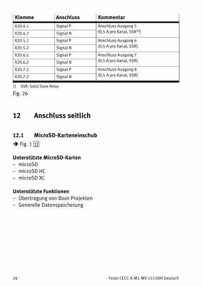
Klemme KommentarAnschluss
X20.4.1 Signal P Anschluss Ausgang 5
(0,5�A pro Kanal, SSR1))X20.4.2 Signal N
X20.5.1 Signal P Anschluss Ausgang 6
(0,5�A pro Kanal, SSR)X20.5.2 Signal N
X20.6.1 Signal P Anschluss Ausgang 7
(0,5�A pro Kanal, SSR)X20.6.2 Signal N
X20.7.1 Signal P Anschluss Ausgang 8
(0,5�A pro Kanal, SSR)X20.7.2 Signal N
1) SSR: Solid State Relay
Fig. 26
12 Anschluss seitlich
12.1 MicroSD-Karteneinschub
� Fig. 1 aB��
Unterstützte MicroSD-Karten– microSD– microSD HC– microSD XC
Unterstützte Funktionen– Übertragung von Boot-Projekten– Generelle Datenspeicherung

Festo CECC-X-M1-MV 1511NH Deutsch 25
13 Technische Daten
Steuerung CECC-X-M1-MV
Betriebsspannung [X1, X5] [V�DC] 19,2 … 30
Betriebsspannung [X21] [V�DC] 19,2 … 50
Stromaufnahme nominal bei�24 VDC [mA] 200
Integrierter Bremschopper
Spannungsbegrenzung Einschalt
schwelle
[V] Betriebsspannung [X21] +�2,0
Spannungsbegrenzung Ausschalt
schwelle
[V] Betriebsspannung [X21] +�0,5
Nominalleistung [W] 18
Dauerleistung [W] �5
Impulsleistung bei Pulsfrequenz�1�Hz
(Einschaltdauer �10%)
[W] �50
Bremswiderstand [Ω] 15
Verpolungsschutz nein
Zulassung RCM
CE-Zeichen � Konformitätserklärung
� www.festo.com/sp
nach EU-EMV-Richtlinie1),2)
Leitungslänge USB-Kabel [m] �3
Leitungslänge Motor-Kabel [m] �3
Sonstige Leitungslängen [m] �10
Schutzart IP20
Schutzklasse III
Schwing- und Schockfestigkeit
(nach�IEC/EN 60068-2-6)
SG1 3)
MicroSD-Speicherkarte
Unterstützte Typen microSD, microSDHC, microSDXC
Kapazität [GByte] �32
Dateisystem FAT32
1) Das Produkt ist für den Einsatz im Industriebereich vorgesehen.
Im Wohnbereich müssen evtl. Maßnahmen zur Funkentstörung getroffen werden.
2) Das Produkt ist nach EN 61131-2:2007 in Zone�A eingestuft.
3) ��13.2 Erläuterung zu Schwingung und Schock – Schärfegrad

Festo CECC-X-M1-MV 1511NH Deutsch26
Steuerung CECC-X-M1-MV
Analoge Eingänge
Eingangssignal [U] 0 ... 10�V
Eingangssignal [I] 0 ... 20�mA
Auflösung Bit 14
Hardware
Prozessor (CPU) Dual Core, 2 x 866 MHz
Arbeitsspeicher gesamt MByte 512
Speicher für ProjektDaten (tempo
rär)
MByte 19,5
Speicher für ProjektDaten
(permanent)
MByte 8
Remanenter Speicher ��13.1 KByte 4
Umgebungstemperatur [°C] 0 … 55
Lagertemperatur [°C] –25 … 70
Produktgewicht [g] 410
Lüftergeräusch LpAeq (1�m Abstand) [dB(A)] 35,7
1) Das Produkt ist für den Einsatz im Industriebereich vorgesehen.
Im Wohnbereich müssen evtl. Maßnahmen zur Funkentstörung getroffen werden.
2) Das Produkt ist nach EN 61131-2:2007 in Zone�A eingestuft.
3) ��13.2 Erläuterung zu Schwingung und Schock – Schärfegrad
Fig. 27
13.1 Remanente Variablen
Zur Speicherung von remanenten Variablen stehen der Steuerung max.4096�Byte zur Verfügung. Die Aufteilung erfolgt dabei automatisch aufBasis der VariablenDeklaration innerhalb der Applikation.Folgende beispielhafte Kombinationen zur Verteilung des remanentenSpeichers sind möglich.
RETAIN Variable PERSISTENT RETAIN Variable
4096 Byte 0�Byte (nur falls keine PERSISTENT Variablenliste angelegt ist)
0 Byte 4052 (44 Byte für Identifikation)
300 Byte 4052 – 300 Byte = 3752 Byte (44 Byte für Identifikation)
x Byte 4052 – x Byte (44 Byte für Identifikation)
Fig. 28

Festo CECC-X-M1-MV 1511NH Deutsch 27
Hinweis
� Stellen Sie bei der Programmierung sicher, dass die Gesamtgrößealler remanenten Daten den max. zur Verfügung stehenden Bereichvon 4096 Byte nicht überschreitet.
Auf diese Weise vermeiden Sie Fehler während der Übertragung einerApplikation auf die Steuerung.
Weitere Informationen finden Sie im Support-Portal vonFesto�� www.festo.com/sp.
Festo CECC-X-M1-MV 1511NH Deutsch28
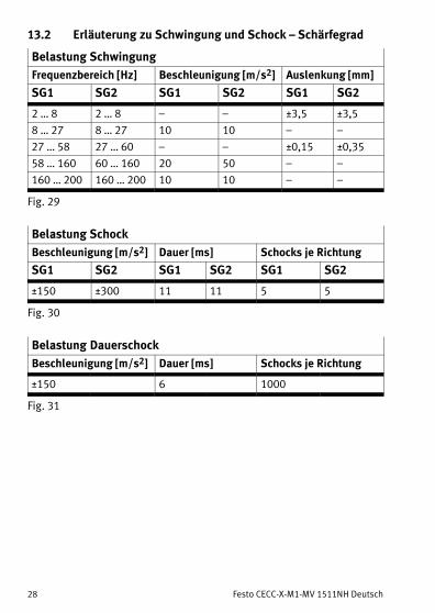
13.2 Erläuterung zu Schwingung und Schock – Schärfegrad
Belastung Schwingung
Frequenzbereich [Hz] Beschleunigung [m/s2] Auslenkung [mm]
SG1 SG2 SG1 SG2 SG1 SG2
2 … 8 2 … 8 – – ±3,5 ±3,5
8 … 27 8 … 27 10 10 – –
27 … 58 27 … 60 – – ±0,15 ±0,35
58 … 160 60 … 160 20 50 – –
160 … 200 160 … 200 10 10 – –
Fig. 29
Belastung Schock
Beschleunigung [m/s2] Dauer [ms] Schocks je Richtung
SG1 SG2 SG1 SG2 SG1 SG2
±150 ±300 11 11 5 5
Fig. 30
Belastung Dauerschock
Beschleunigung [m/s2] Dauer [ms] Schocks je Richtung
±150 6 1000
Fig. 31

Festo CECC-X-M1-MV 1511NH English 29
English1 Safety
1.1 General safety information
� Observe the safety instructions in the corresponding chapters.
Special safety regulations are placed immediately before thetask instruction.
Warning
Electric voltageRisk of injuries caused by electric shock, damage to the machine andsystem.Danger of electric shock from voltage sources.Before carrying out mounting, installation and/or maintenance work:� Switch off the supply voltage and safeguard it against being
switched on again unintentionally.� Use only power sources which guarantee reliable electrical isolation
of the operating voltage in accordance withIEC�60204-1/EN�60204-1.
� Switch the voltages back on only after completion of work.
Note
Unauthorised access to the product can cause damage or malfunctions.When connecting the product to a network:� Protect the network from unauthorised access.Measures to protect the network include: firewall, Intrusion PreventionSystem (IPS), network segmentation, virtual LAN (VLAN), virtualprivate network (VPN), security at physical access level (port security).Further information � Directives and standards on information technology security, e.g. IEC 62443, ISO/IEC 27001. An access passwordprotects only against accidental changes.
Festo CECC-X-M1-MV 1511NH English30
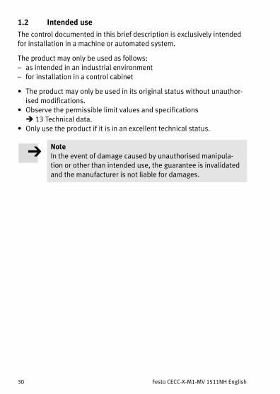
1.2 Intended use
The control documented in this brief description is exclusively intendedfor installation in a machine or automated system.
The product may only be used as follows:– as intended in an industrial environment– for installation in a control cabinet
� The product may only be used in its original status without unauthorised modifications.
� Observe the permissible limit values and specifications� 13�Technical data.
� Only use the product if it is in an excellent technical status.
NoteIn the event of damage caused by unauthorised manipulation or other than intended use, the guarantee is invalidatedand the manufacturer is not liable for damages.

Festo CECC-X-M1-MV 1511NH English 31
2 Requirements for product use
� Make this brief description available to the design engineer, installerand personnel responsible for commissioning of the machine or system in which these products are used.
� Make sure that the specifications of the documentation are alwayscomplied with. Also consider the documentation for the other components and modules � 13�Technical data.
� Take into consideration the legal regulations applicable at the installation site, as well as:– regulations and standards– regulations of the testing organisations and insurers– national specifications
2.1 Training of skilled personnel
The following steps must only be carried out by qualified specialists:– mounting– installation– commissioning– maintenance– repair
The trained personnel must be familiar with:– electrical control technology– the applicable regulations for operating safety-engineered systems– the applicable regulations for accident prevention and occupational
safety

Festo CECC-X-M1-MV 1511NH English32
3 Scope of delivery
– Controller CECC-X-M1-MV– This brief description
Software for the product can be found in the Festo SupportPortal � www.festo.com/sp.
4 Accessories
– Camera– Plug assortment
Catalogue � www.festo.com/sp
Please consult your regional Festo contact if you have any technicalqueries or questions regarding the accessories.
Festo CECC-X-M1-MV 1511NH English 33
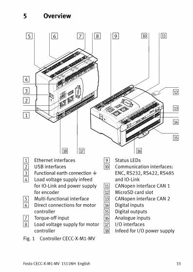
5 Overview
aF
aD
aE
4
1
2
3
5 6 7 8 aJ aA
aB
aC
9
aH aG
1 Ethernet interfaces2 USB interfaces3 Functional earth connection��4 Load voltage supply infeed
for IO-Link and power supplyfor encoder
5 Multi-functional interface6 Direct connections for motor
controller7 Torque-off input8 Load voltage supply for motor
controller
9 Status LEDsaJ Communication interfaces:
ENC, RS232, RS422, RS485and IO-Link
aA CANopen interface CAN�1aB MicroSD card slotaC CANopen interface CAN�2aD Digital inputsaE Digital outputsaF Analogue inputsaG I/O interfacesaH Infeed for I/O power supply
Fig. 1 Controller CECC-X-M1-MV
Festo CECC-X-M1-MV 1511NH English34
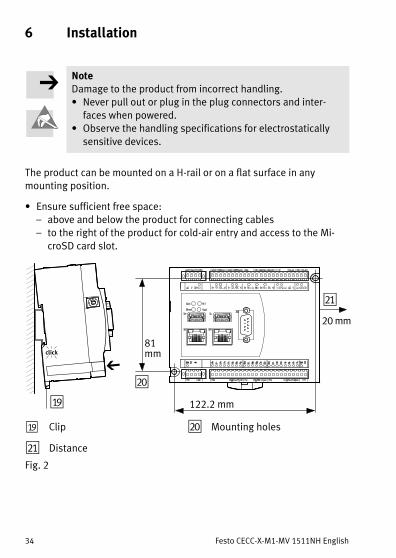
6 Installation
NoteDamage to the product from incorrect handling.� Never pull out or plug in the plug connectors and inter
faces when powered.� Observe the handling specifications for electrostatically
sensitive devices.
The product can be mounted on a H-rail or on a flat surface in anymounting position.
� Ensure sufficient free space:– above and below the product for connecting cables– to the right of the product for cold-air entry and access to the Mi
croSD card slot.
81 mm
122.2 mm
bJ
aI
20 mm
bA
aI Clip
bA Distance
bJ Mounting holes
Fig. 2
Festo CECC-X-M1-MV 1511NH English 35
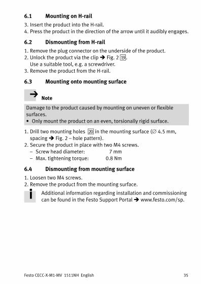
6.1 Mounting on H-rail
3. Insert the product into the H-rail.4. Press the product in the direction of the arrow until it audibly engages.
6.2 Dismounting from H-rail
1. Remove the plug connector on the underside of the product.2. Unlock the product via the clip � Fig. 2�aI ��.
Use a suitable tool, e.g. a screwdriver.3. Remove the product from the H-rail.
6.3 Mounting onto mounting surface
Note
Damage to the product caused by mounting on uneven or flexiblesurfaces.� Only mount the product on an even, torsionally rigid surface.
1. Drill two mounting holes bJ� in the mounting surface (�4.5 mm,spacing � Fig. 2 – hole pattern).
2. Secure the product in place with two M4 screws.– Screw head diameter: 7 mm– Max. tightening torque: 0.8 Nm
6.4 Dismounting from mounting surface
1. Loosen two M4 screws.2. Remove the product from the mounting surface.
Additional information regarding installation and commissioningcan be found in the Festo Support Portal � www.festo.com/sp.

Festo CECC-X-M1-MV 1511NH English36
7 Status LEDsThe product is equipped with the following status LEDs � Fig. 1 9:
Status LED Meaning Status LED Meaning
Run Application status Net Device detected
Error Error Mod Reserved
Fig. 3
8 Power supplies
Note� Use an external overload protection for the power supply
of the device.� Pay attention to the required current consumption.
8.1 Power supply [X1]for device, digital/analogue inputs and motor controller direct connection (logic)
Residual current for all supplied ports: 750 mAof which intrinsic current consumption: �200 mA
Terminal Port Comments
X1.1 24 U+ power supply
X1.2 0 U– load
X1.3 � Functional earth
X1.4 – Not connected
Fig. 4
Festo CECC-X-M1-MV 1511NH English 37
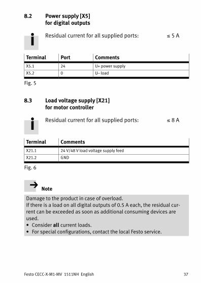
8.2 Power supply [X5] for digital outputs
Residual current for all supplied ports: �5 A
Terminal Port Comments
X5.1 24 U+ power supply
X5.2 0 U– load
Fig. 5
8.3 Load voltage supply [X21] for motor controller
Residual current for all supplied ports: �8 A
Terminal Comments
X21.1 24 V/48 V load voltage supply feed
X21.2 GND
Fig. 6
Note
Damage to the product in case of overload.If there is a load on all digital outputs of 0.5 A each, the residual current can be exceeded as soon as additional consuming devices areused.� Consider all current loads.� For special configurations, contact the local Festo service.

Festo CECC-X-M1-MV 1511NH English38
8.4 Load voltage supply [X11] for IO-Link
This port is used for the power supply of an IO-Link device that is connected via the IO-Link master port.
Current consumption for IO-Link: �0.75 A
Note
Damage to the product in the event of a mix-up of the connecting pins.� When establishing the load voltage supply for the IO-Link master
port, make sure that only connecting pins X11.1 and X11.2 areused.
Terminal Port Comments Internalconnection
X11.1 24 UA+ Infeed for IO-Link master port X15.4
X11.2 0 UA– Infeed for IO-Link master port X15.5
Fig. 7
8.5 Power supply [X11] for encoder
Encoder current consumption: �0.3 A
Terminal
Port Comments
X11.3 UG Encoder power supply (ground)
X11.4 UE Encoder power supply (5 V)
Fig. 8

Festo CECC-X-M1-MV 1511NH English 39
9 Interfaces, front
[X6][X10][X8]
[X1]
[X9][X7]
[X11] [X12] [X13] [X14] [X15] [X16]
[X2] [X3] [X4] [X5]
Fig. 9
9.1 I/O interface [X2, X3, X4]
Terminal Comments
X2.0 … X2.1 2 high-speed digital inputs (200 kHz)
X2.2 … X2.71),2) 6 digital inputs (1 kHz, IEC type�1)
X3.0 … X3.5 6 digital inputs (1 kHz, IEC type�1)
X4.0 … X4.73) 8 digital outputs (0.7 A per channel, PNP, SSR4))
1) X2.2 and X2.3 optionally also serve as MachineVision inputs (e.g. Trigger)
2) X2.3 also serves as a latch input for the encoder via the multiple interface X14
3) X4.0 ... X4.2 optionally also serve as MachineVision outputs (e.g. flash output)
4) SSR: Solid State Relay
Fig. 10

Festo CECC-X-M1-MV 1511NH English40
9.2 CANopen interface CAN�1 [X6]
Pin Port Comments
1 – Not connected
2 CAN1_L1) CANBus signal�1 (dominant low)
3 CAN_GND CAN Ground
4 – Not connected
5 CAN_SHLD Connection to functional earth
6 CAN_GND CAN Ground (optional)
7 CAN1_H1) CANBus signal�1 (dominant high)
8 – Not connected
9 – Not connected
1) For connection of the device at the end of the line: Connect Pin2 and Pin7 via a resistor.
A corresponding plug with resistor (120 Ω/0.25 W) can be found in Festo's accessor
ies�� www.festo.com/catalogue
Fig. 11
9.3 USB interfaces [X7, X9]
The USB interfaces � Fig. 1 2 are compatible with the USB 3.0 and USB2.0 standards. They are suitable for USB plug type A.The following functions are supported (cable length� 3 m):– Transfer of boot projects– General data storage– Connection of a camera– Connection of hardware extensions
Note
Damage to the product.� Only use USB components with a current consumption �0.9 A.
Please consult your regional Festo contact if you have any queries regarding the extensions.

Festo CECC-X-M1-MV 1511NH English 41
9.4 Ethernet interfaces [X8, X10]
The Ethernet interfaces � Fig. 1 1 are designed as an RJ45 socket andsupport Gigabit LAN. The controller cannot be used as a switch.The following functions are supported:
X8 X10
– TCP/IP (e.g. Modbus TCP)– UDP (e.g. network variables, EasyIP)– EtherNet/IP (e.g. Generic IODevice)
– EtherCATMaster
Fig. 12
Certain settings can be configured using a web browser and theIP address of the device � http://192.168.4.2 net mask:255.255.0.0 gateway:�192.168.1.1
9.5 Serial interfaces [X12, X13]
– X12 = RS232-1– X13 = RS232-2
Terminal Port Comments
X12.1, X13.1 G Load
X12.2, X13.2 Tx Transmitted data1) (output)
X12.3, X13.3 Rx Received data1) (input)
X12.4, X13.4 S Screening, connection to functional earth
1) Max. level: low –15�V high +15�V; TTL level not permissible!
Fig. 13
Festo CECC-X-M1-MV 1511NH English42
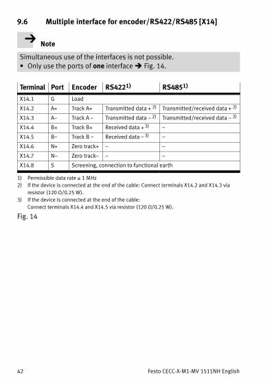
9.6 Multiple interface for encoder/RS422/RS485 [X14]
Note
Simultaneous use of the interfaces is not possible.� Only use the ports of one interface � Fig. 14.
Terminal Port Encoder RS4221) RS4851)
X14.1 G Load
X14.2 A+ Track A+ Transmitted data + 2) Transmitted/received data + 2)
X14.3 A– Track A�– Transmitted data – 2) Transmitted/received data�– 2)
X14.4 B+ Track B+ Received data + 3) –
X14.5 B– Track B�– Received data – 3) –
X14.6 N+ Zero track+ – –
X14.7 N– Zero track– – –
X14.8 S Screening, connection to functional earth
1) Permissible data rate �1 MHz
2) If the device is connected at the end of the cable: Connect terminals X14.2 and X14.3 via
resistor�(120 Ω/0.25 W).
3) If the device is connected at the end of the cable:
Connect terminals X14.4 and X14.5 via resistor�(120 Ω/0.25 W).
Fig. 14

Festo CECC-X-M1-MV 1511NH English 43
9.7 Communication interface for IO-Link [X15, X16]
IO-Link Master
Terminal Port Comments
X15.1 L+ 24 V
X15.2 C/Q IO-Link communication signal
X15.3 L– 0 V
X15.4 24 UA+
X15.5 0 UA–
Fig. 15
IO-Link device
Terminal Port Comments
X16.1 L+ 24 V
X16.2 C/Q IO-Link communication signal
X16.3 L– 0 V
Fig. 16

Festo CECC-X-M1-MV 1511NH English44
10 Direct connections, top
[X21] [X24]
[X25] [X28]
[X23] Drive�B[X22] Drive�A
[X27] Drive��D[X26] Drive��C
1 2 3 4 5 6 7 8 9 10
1 2 3 4 5 6 7 8 9 10
1 2 3 4 5 6 7 8 9 10
1 2 3 4 5 6 7 8 9 10
1 2 3
1 2 3
1 2
1 2
Fig. 17
10.1 Motor controller A, B, C, D [X22,�X23,�X26,�X27]with CANopen interface CAN�2
Residual current for all supplied ports: �8 Acable length: �3 m
Terminal Port Comments Internalconnection
X2x.1 24/48 VDC Load voltage supply for motor
controller1)X21.1
X2x.2 GND X21.2
X2x.3 24 VDC Power supply for motor controller
(logic)X1.1
X2x.4 GND X1.2
X2x.5 CAN2_H CANBus signal�2 (dominant high) X18.1
X2x.6 CAN2_L CANBus signal�2 (dominant low) X18.2
X2x.7 CAN_GND CAN Ground X18.3
X2x.8 CAN_SHLD Connection to functional earth X18.4
1) Continuous load per output: �2.0 A
Impulse current per output: �4.2 A
Festo CECC-X-M1-MV 1511NH English 45
Terminal Port Comments Internalconnection
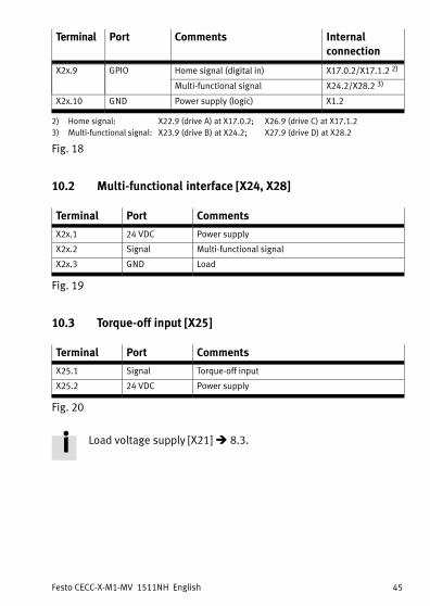
X2x.9 GPIO Home signal (digital in) X17.0.2/X17.1.2 2)
Multi-functional signal X24.2/X28.2 3)
X2x.10 GND Power supply (logic) X1.2
2) Home signal: X22.9 (drive�A) at X17.0.2; X26.9 (drive�C) at X17.1.2
3) Multi-functional signal: X23.9 (drive�B) at X24.2; X27.9 (drive�D) at X28.2
Fig. 18
10.2 Multi-functional interface [X24, X28]
Terminal Port Comments
X2x.1 24 VDC Power supply
X2x.2 Signal Multi-functional signal
X2x.3 GND Load
Fig. 19
10.3 Torque-off input [X25]
Terminal Port Comments
X25.1 Signal Torque-off input
X25.2 24 VDC Power supply
Fig. 20
Load voltage supply [X21]�� 8.3.

Festo CECC-X-M1-MV 1511NH English46
11 Direct connections, bottom
[X19] Analogue input Digital output [X20]
[X17] Digital input CAN 2 [X18]
0.1 1.1 2.1 3.1 4.1 5.1 6.1 7.1 1 2 3 4
0.1 1.1 3.12.1 0.1 1.1 2.1 3.1 4.1 5.1 6.1 7.1
Fig. 21
11.1 Digital inputs [X17]
The digital inputs, configured in 3-wire connection technology, are notgalvanically separated. The ground potential for all inputs relates to GNDof the power supply [X1].� Always use 3 adjacent terminals when connecting a sensor with a
3-wire configuration.
Terminal Port Comments
X17.0.1 24 VDC Connection for digital sensor�1
(1 kHz, IEC type�1)X17.0.2 Signal�1 / home signal for drive A
X17.0.3 GND logic
X17.1.1 24 VDC Connection for digital sensor�2
(1 kHz, IEC type�1)X17.1.2 Signal�2 / home signal for drive C
X17.1.3 GND logic
X17.2.1 24 VDC Connection for digital sensor�3
(1 kHz, IEC type�1)X17.2.2 Signal 3
X17.2.3 GND logic

Festo CECC-X-M1-MV 1511NH English 47
Terminal CommentsPort
X17.3.1 24 VDC Connection for digital sensor�4
(1 kHz, IEC type�1)X17.3.2 Signal 4
X17.3.3 GND logic
X17.4.1 24 VDC Connection for digital sensor�5
(1 kHz, IEC type�1)X17.4.2 Signal 5
X17.4.3 GND logic
X17.5.1 24 VDC Connection for digital sensor 6
(1 kHz, IEC type�1)X17.5.2 Signal 6
X17.5.3 GND logic
X17.6.1 24 VDC Connection for digital sensor�7
(1 kHz, IEC type�1)X17.6.2 Signal 7
X17.6.3 GND logic
X17.7.1 24 VDC Connection for digital sensor�8
(1 kHz, IEC type�1)X17.7.2 Signal 8
X17.7.3 GND logic
Fig. 22
The inputs can be adjusted for PNP or NPN sensors.Configuration is effected via CoDeSys parameters in the controlproject for all inputs together.
11.2 CANopen interface CAN�2 [X18]
Terminal Port Comments
X18.1 CAN2_H1) CANBus signal�2 (dominant high)
X18.2 CAN2_L1) CANBus signal�2 (dominant low)
X18.3 CAN_GND CAN Ground
X18.4 CAN_SHLD Connection to functional earth
1) No terminating resistor necessary; ports are connected internally via a resistor.
Fig. 23
Festo CECC-X-M1-MV 1511NH English48
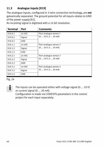
11.3 Analogue inputs [X19]
The analogue inputs, configured in 3-wire connection technology, are notgalvanically separated. The ground potential for all inputs relates to GNDof the power supply [X1].An incoming signal is digitised with a 14 bit resolution.
Terminal Port Comments
X19.0.1 24 VDC Port analogue sensor 1
(0 ... 10 V; 0 ... 20 mA)X19.0.2 Signal
X19.0.3 GND
X19.1.1 24 VDC Port analogue sensor 2
(0 ... 10 V; 0 ... 20 mA)X19.1.2 Signal
X19.1.3 GND
X19.2.1 24 VDC Port analogue sensor 3
(0 ... 10 V; 0 ... 20 mA)X19.2.2 Signal
X19.2.3 GND
X19.3.1 24 VDC Port analogue sensor 4
(0 ... 10 V; 0 ... 20 mA)X19.3.2 Signal
X19.3.3 GND
Fig. 24
The inputs can be operated either with voltage signal (0 ... 10 V)or current signal (0�... 20 mA).Configuration is made via CODESYS parameters in the controlproject for each input separately.
Festo CECC-X-M1-MV 1511NH English 49
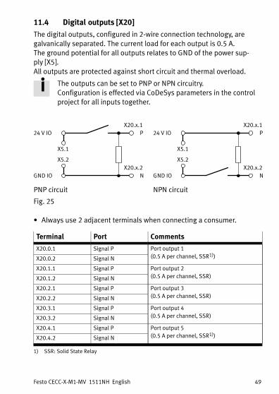
11.4 Digital outputs [X20]
The digital outputs, configured in 2-wire connection technology, aregalvanically separated. The current load for each output is 0.5 A.The ground potential for all outputs relates to GND of the power supply [X5].All outputs are protected against short circuit and thermal overload.
The outputs can be set to PNP or NPN circuitry.Configuration is effected via CoDeSys parameters in the controlproject for all inputs together.
24 V IO
GND IO
P
N
X5.1
X5.2
X20.x.1
X20.x.2
PNP circuit
24 V IO
GND IO
P
N
X5.1
X5.2
X20.x.1
X20.x.2
NPN circuit
Fig. 25
� Always use 2 adjacent terminals when connecting a consumer.
Terminal Port Comments
X20.0.1 Signal P Port output 1
(0.5 A per channel, SSR1))X20.0.2 Signal N
X20.1.1 Signal P Port output 2
(0.5 A per channel, SSR)X20.1.2 Signal N
X20.2.1 Signal P Port output 3
(0.5 A per channel, SSR)X20.2.2 Signal N
X20.3.1 Signal P Port output 4
(0.5 A per channel, SSR)X20.3.2 Signal N
X20.4.1 Signal P Port output 5
(0.5 A per channel, SSR1))X20.4.2 Signal N
1) SSR: Solid State Relay

Festo CECC-X-M1-MV 1511NH English50
Terminal CommentsPort
X20.5.1 Signal P Port output 6
(0.5 A per channel, SSR)X20.5.2 Signal N
X20.6.1 Signal P Port output 7
(0.5 A per channel, SSR)X20.6.2 Signal N
X20.7.1 Signal P Port output 8
(0.5 A per channel, SSR)X20.7.2 Signal N
1) SSR: Solid State Relay
Fig. 26
12 Port on side
12.1 MicroSD card slot
� Fig. 1 aB��
Supported MicroSD cards– microSD– microSD HC– microSD XC
Supported functions– Transfer of boot projects– General data storage

Festo CECC-X-M1-MV 1511NH English 51
13 Technical data
Controller CECC-X-M1-MV
Operating voltage [X1, X5] [V�DC] 19.2 … 30
Operating voltage [X21] [V�DC] 19.2 … 50
Current consumption nominal at 24 VDC [mA] 200
Integrated brake chopper
Voltage limitation switch-on
threshold
[V] Operating voltage [X21] +�2.0
Voltage limitation switch-off
threshold
[V] Operating voltage [X21] +�0.5
Nominal power [W] 18
Continuous power [W] �5
Pulse power with pulse frequency
1 Hz (switch-on duration �10 %)
[W] �50
Braking resistor [Ω] 15
Protection against incorrect polarity No
Certification RCM
CE marking � Declaration of conformity
� www.festo.com/sp
in accordance with EU EMC Direct
ive 1),2)
USB cable length [m] �3
Motor cable length [m] �3
Other cable lengths [m] �10
Degree of protection IP20
Protection class III
Vibration and shock resistance (in ac
cordance with IEC/EN 60068-2-6)
SL1 3)
MicroSD memory card
Supported types microSD, microSDHC, microSDXC
Capacity [GByte] �32
File system FAT32
1) The product is intended for use in industrial environments.
Measures for interference suppression may need to be implemented in residential areas.
2) The product is classified in zone A in accordance with EN 61131-2:2007.
3) ��13.2 Explanation on vibration and shock – severity level
Festo CECC-X-M1-MV 1511NH English52
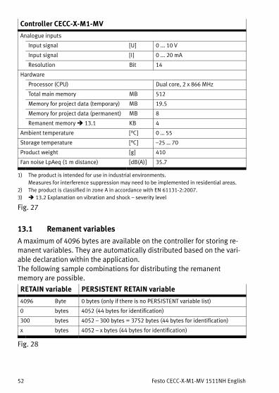
Controller CECC-X-M1-MV
Analogue inputs
Input signal [U] 0 ... 10 V
Input signal [I] 0 ... 20 mA
Resolution Bit 14
Hardware
Processor (CPU) Dual core, 2 x 866 MHz
Total main memory MB 512
Memory for project data (temporary) MB 19.5
Memory for project data (permanent) MB 8
Remanent memory � 13.1 KB 4
Ambient temperature [°C] 0 … 55
Storage temperature [°C] –25 … 70
Product weight [g] 410
Fan noise LpAeq (1 m distance) [dB(A)] 35.7
1) The product is intended for use in industrial environments.
Measures for interference suppression may need to be implemented in residential areas.
2) The product is classified in zone A in accordance with EN 61131-2:2007.
3) ��13.2 Explanation on vibration and shock – severity level
Fig. 27
13.1 Remanent variables
A maximum of 4096 bytes are available on the controller for storing remanent variables. They are automatically distributed based on the variable declaration within the application.The following sample combinations for distributing the remanentmemory are possible.
RETAIN variable PERSISTENT RETAIN variable
4096 Byte 0 bytes (only if there is no PERSISTENT variable list)
0 bytes 4052 (44 bytes for identification)
300 bytes 4052 – 300 bytes = 3752 bytes (44 bytes for identification)
x bytes 4052 – x bytes (44 bytes for identification)
Fig. 28
Festo CECC-X-M1-MV 1511NH English 53
Note
� Make sure during programming that the total size of all the remanent data does not exceed the maximum available range of4096 bytes.
This will avoid errors when transferring an application to the controller.
Additional information can be found in the Festo SupportPortal � www.festo.com/sp.
Festo CECC-X-M1-MV 1511NH English54
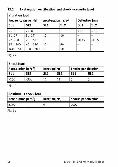
13.2 Explanation on vibration and shock – severity level
Vibration load
Frequency range [Hz] Acceleration [m/s2] Deflection [mm]
SL1 SL2 SL1 SL2 SL1 SL2
2 … 8 2 … 8 – – ±3.5 ±3.5
8 … 27 8 … 27 10 10 – –
27 … 58 27 … 60 – – ±0.15 ±0.35
58 … 160 60 … 160 20 50 – –
160 … 200 160 … 200 10 10 – –
Fig. 29
Shock load
Acceleration [m/s2] Duration [ms] Shocks per direction
SL1 SL2 SL1 SL2 SL1 SL2
±150 ±300 11 11 5 5
Fig. 30
Continuous shock load
Acceleration [m/s2] Duration [ms] Shocks per direction
±150 6 1000
Fig. 31


