
www.lumberg.com 09/2015
0322
*a Dichtunggasketjoint d’étanchéité
*c Schirmungshieldingblindage
Polbilder, von der Lötseite gesehenPin configurations, solder side viewSchémas de raccordement, vus du côté à souder
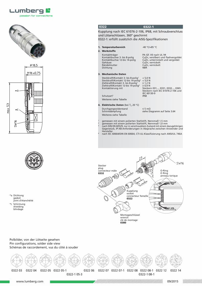
Kupplung nach IEC 61076-2-106, IP68, mit Schraub verschlussund Löt an schlüs sen, 360° geschirmt0322-1: erfüllt zusätzlich die AISG-Spezifikationen
1. Temperaturbereich -40 °C/+85 °C
2. Werkstoffe
Kontaktträger PA GF, V0 nach UL 94Kontaktbuchse 3- bis 8-polig CuZn, versilbert und flashvergoldetKontaktbuchse 12-bis 14-polig CuZn, unternickelt und vergoldetGehäuse CuZn, vernickeltRändelmutter CuZn, vernickeltDichtung NBR
3. Mechanische Daten
Steckkraft/Kontakt 3- bis 8-polig1 < 5,0 NSteckkraft/Kontakt 12-bis 14-polig2 < 5,0 NZiehkraft/Kontakt 3- bis 8-polig1 ≥ 1,2 NZiehkraft/Kontakt 12-bis 14-polig2 ≥ 0,9 NKontaktierung mit Steckern 031..., 0331, 0332..., 0365
Steckern nach IEC 61076-2-106 undIEC 60130-9
Schutzart3 IP68
Weiteres siehe Tabelle
4. Elektrische Daten (bei TU 20 °C)
Durchgangswiderstand ≤ 5 mΩSchirmdämpfung siehe Diagramm auf Seite 3.64
Weiteres siehe Tabelle
1 gemessen mit einem polierten Stahlstift, Nennmaß 1,5 mm2 gemessen mit einem polierten Stahlstift, Nennmaß 1,0 mm3 nach DIN EN 60529, nur in verschraubtem Zustand mit einem dazugehörigen
Gegenstück, IP-X8-Anforderungen in Absprache zwischen Anwender und Hersteller
4 nach IEC 60664/DIN EN 60664, CTI-UL-Klassifizierung nach ANSI/UL 746A
Montageschlüsselwrenchclé de montage0380
Kupplungsocketconnecteur femelle0322
Steckerplugconnecteur mâle0332
O-RingO Ringanneau torique
0322-1
0322 03 0322 04 0322 05 0322 05-1 0322 06 0322 07 0322 07-1 0322 08 0322 08-1 0322 12 0322 140322-1 05-3 0322-1 08-1
www.lumberg.com 09/2015
Rundsteckverbinder mit Schraubverschluss nach IEC 61076-2-106 und AISG-Spezifikation, IP68Circular connectors with threaded joint acc. to IEC 61076-2-106 and AISG specification, IP68
Connecteurs circulaires avec verrouillage à vis suivant CEI 61076-2-106 et spécification AISG, IP68
0322 0322
Socket acc. to IEC 61076-2-106, IP68, with threaded jointand solder terminals, 360° shielded0322-1: also complies with AISG specifications
1. Temperature range -40 °C/+85 °C
2. Materials
Insulating body PA GF, V0 according to UL 94Contact bush 3 to 8 poles CuZn, silver and flash gold-platedContact bush 12 to 14 poles CuZn, pre-nickel and gold-platedHousing CuZn, nickel-platedKnurled nut CuZn, nickel-platedGasket NBR
3. Mechanical data
Insertion force/contact 3–8 poles1 < 5.0 NInsertion force/contact 12–14 poles2 < 5.0 NWithdrawal force/contact 3–8 poles1 ≥ 1.2 NWithdrawal force/cont. 12–14 poles2 ≥ 0.9 NMating with plugs 031..., 0331, 0332..., 0365
plugs according to IEC 61076-2-106and IEC 60130-9
Protection3 IP68
For further information see table
4. Electrical data (at Tamb 20 °C)
Contact resistance ≤ 5 mΩAttenuation see graph on page 3.64
For further information see table
1 measured with a polished steel pin, nominal thickness 1.5 mm2 measured with a polished steel pin, nominal thickness 1.0 mm3 according to DIN EN 60529, only in locked position with a proper counter
part, IP X8 requirements under agreement between user and manufac-turer
4 acc. to IEC 60664/DIN EN 60664, CTI UL classification acc. to ANSI/UL 746A
Connecteur femelle suivant CEI 61076-2-106, IP68, avec ver-rouillage à vis et connexion par soudure, blindé à 360°0322-1: aussi conforme aux spécifications AISG
1. Température d’utilisation -40 °C/+85 °C
2. Matériaux
Corps isobody PA GF, V0 suivant UL 94Prise de contact 3 à 8 pôles CuZn, argenté et doré flashPrise de contact 12 à 14 pôles CuZn, sous-nickelé et doréBoîtier CuZn, nickeléÉcrou moleté CuZn, nickeléJoint d’étanchéité NBR
3. Caractéristiques mécaniques
Force d’insertion/contact 3–8 pôles1 < 5,0 NForce d’insertion/cont. 12–14 pôles2 < 5,0 NForce de séparation/con. 3–8 pôles1 ≥ 1,2 NForce de séparation/cont. 12–14 pôles2 ≥ 0,9 NRaccordement avec connecteurs mâles 031..., 0331,
0332..., 0365connecteurs mâles suivantCEI 61076-2-106 et CEI 60130-9
Protection3 IP68
Pour plus de détails, voir tableau
4. Caractéristiques électriques (à Tamb 20 °C)
Résistance de contact ≤ 5 mΩAtténuation voir graphique à la page 3.64
Pour plus de détails, voir tableau
1 mesurée avec une tige d’acier poli, épaisseur nominale 1,5 mm2 mesurée avec une tige d’acier poli, épaisseur nominale 1,0 mm3 suivant DIN EN 60529, uniquement à l’état verrouillé avec un propre
pendant, exigences IP X8 après entente entre utilisateur et fabricant4 suivant CEI 60664/DIN EN 60664, classification CTI UL suivant ANSI/UL 746A
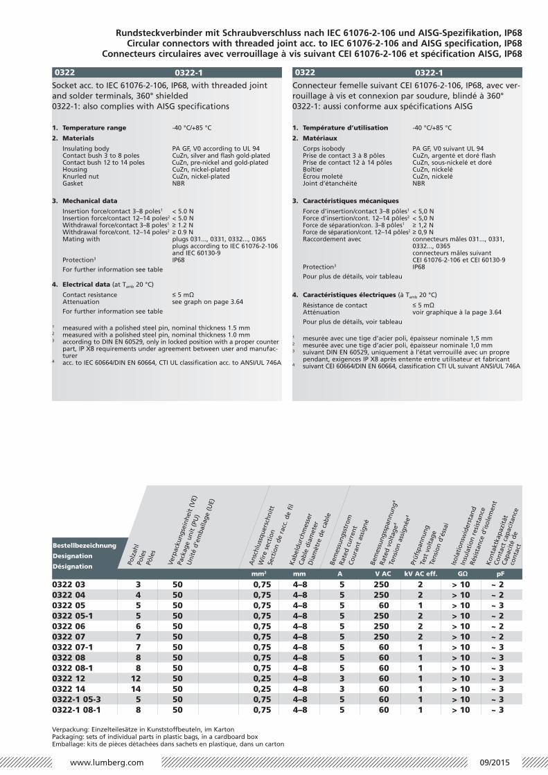
Verpackung: Einzelteilesätze in Kunststoffbeuteln, im KartonPackaging: sets of individual parts in plastic bags, in a cardboard boxEmballage: kits de pièces détachées dans sachets en plastique, dans un carton
Bestellbezeichnung
Designation
Désignation
0322 03 3 50 0,75 4–8 5 250 2 > 10 ~ 20322 04 4 50 0,75 4–8 5 250 2 > 10 ~ 20322 05 5 50 0,75 4–8 5 60 1 > 10 ~ 30322 05-1 5 50 0,75 4–8 5 250 2 > 10 ~ 20322 06 6 50 0,75 4–8 5 250 2 > 10 ~ 20322 07 7 50 0,75 4–8 5 250 2 > 10 ~ 20322 07-1 7 50 0,75 4–8 5 60 1 > 10 ~ 30322 08 8 50 0,75 4–8 5 60 1 > 10 ~ 30322 08-1 8 50 0,75 4–8 5 60 1 > 10 ~ 30322 12 12 50 0,25 4–8 3 60 1 > 10 ~ 30322 14 14 50 0,25 4–8 3 60 1 > 10 ~ 30322-1 05-3 5 50 0,75 4–8 5 60 1 > 10 ~ 30322-1 08-1 8 50 0,75 4–8 5 60 1 > 10 ~ 3
Polz
ahl
Pole
sPô
les
Verp
acku
ngse
inhe
it (
VE)
Pack
age
unit
(PU
)U
nité
d’e
mba
llage
(U
E)
Ans
chlu
ssqu
ersc
hnit
t
Wir
e se
ctio
nSe
ctio
n de
rac
c. d
e fi
lK
abel
durc
hmes
ser
Cabl
e di
amet
erD
iam
ètre
de
cabl
eBe
mes
sung
sstr
omRa
ted
curr
ent
Cour
ant
assi
gné
Bem
essu
ngss
pann
ung
4
Rate
d vo
ltag
e4
Tens
ion
assi
gnée
4
Prüf
span
nung
Test
vol
tage
Tens
ion
d’és
sai
Isol
atio
nsw
ider
stan
d
Insu
lati
on r
esis
tanc
e
Rési
stan
ce d
’isol
emen
tK
onta
ktka
pazi
tät
Cont
act
capa
cita
nce
Capa
cité
de
cont
act
mm2 mm A V AC kV AC eff. GΩ pF
0322-1 0322-1


