Center for Nondestructive Evaluation Zerstörungsfreie Charakterisierung der Degradation von Werkstoffen und Bauteilen im Einsatz Nach wie vor eine Herausforderung für konventionelle und moderne Werkstoffe zur Anwendung im Leichtbau Norbert Meyendorf
Transcript
Center for Nondestructive Evaluation
Zerstörungsfreie Charakterisierung der Degradation von Werkstoffen und Bauteilen im
Einsatz
Nach wie vor eine Herausforderung für konventionelle und moderne Werkstoffe zur Anwendung im Leichtbau
Norbert Meyendorf
Center for Nondestructive Evaluation2
de Havilland CometBOAC Flight 781 and South African Airways Flight 201
Two de Havilland Comet passenger jets broke up in mid-air and crashed within a few months of each other in 1954. As a result, systematic tests were conducted on a fuselage immersed and pressurized in a water tank. After the equivalent of 3,000 flights investigators at the Royal Aircraft Establishment (RAE) were able to conclude that the crash had been due to failure of the pressure cabin at the forward Automatic Direction Finder window in the roof. This 'window' was in fact one of two apertures for the aerials of an electronic navigation system in which opaque fiberglass panels took the place of the window 'glass'. The failure was a result of metal fatigue caused by the repeated pressurization and de-pressurization of the aircraft cabin.
CC BY‐SA 3.0, https://commons.wikimedia.org/w/index.php?curid=2088812
Center for Nondestructive Evaluation3
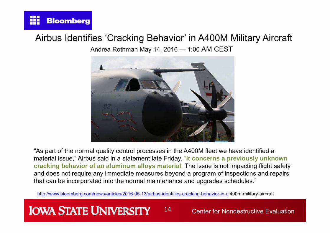
Damage Airbus Cracks
Airbus orders more frequent A380 wing inspections due to fatigue checks
Europe's Airbus (AIR.PA) has ordered more frequent inspections of the wings of the world's largest passenger jet after discovering unexpected levels of metal fatigue during testing on an A380 factory mock-up, industry sources said on Thursday.
New MaterialsThe introduction of new materials and technologies requires a multitude of investigations and verifications known as testing pyramid starting with coupons and components to complete aircraft structures. Static and dynamic properties are examined
Coupon test Panel test Barrel test Full scale fatigue testCurved Panel test
Center for Nondestructive Evaluation6
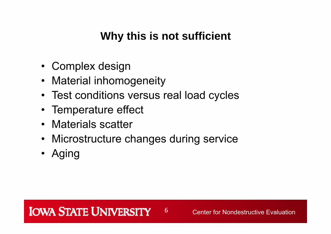
Why this is not sufficient
• Complex design• Material inhomogeneity• Test conditions versus real load cycles• Temperature effect • Materials scatter • Microstructure changes during service• Aging
Center for Nondestructive Evaluation7
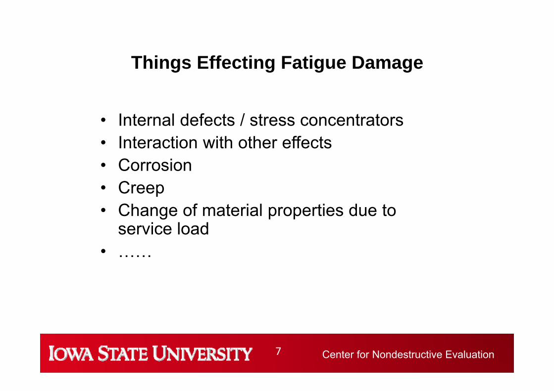
Things Effecting Fatigue Damage
• Internal defects / stress concentrators• Interaction with other effects• Corrosion • Creep• Change of material properties due to
service load• ……
Center for Nondestructive Evaluation8
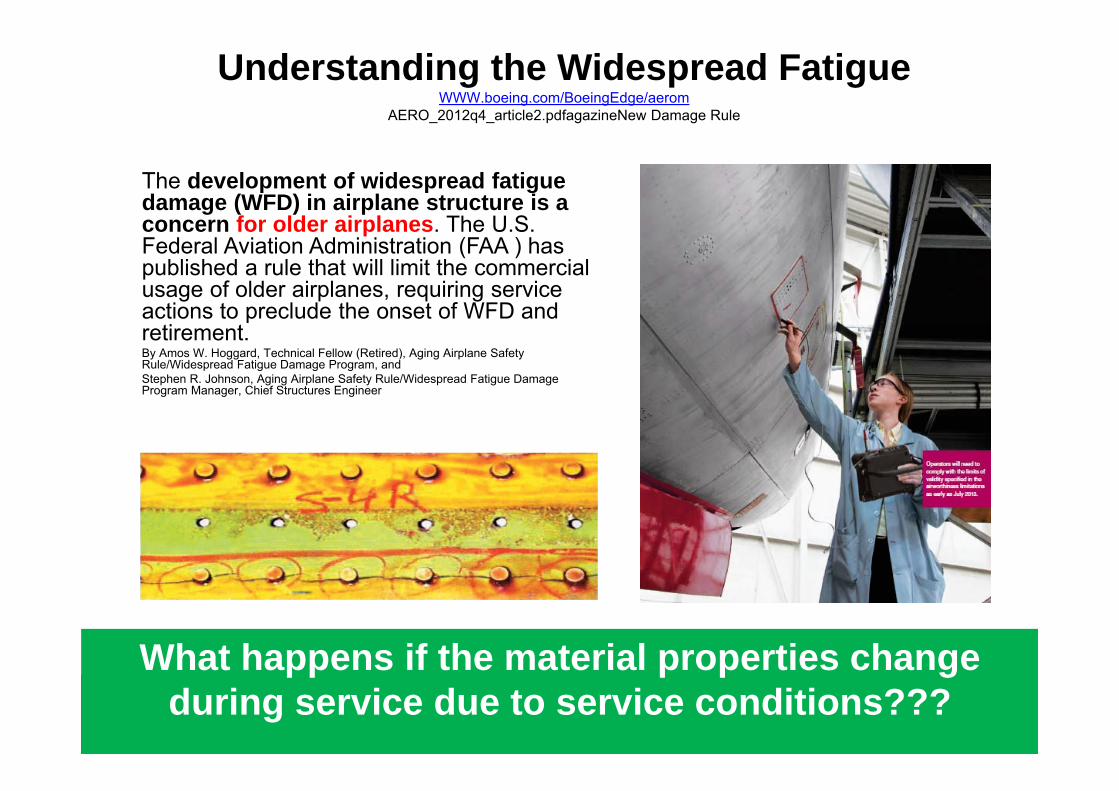
Understanding the Widespread FatigueWWW.boeing.com/BoeingEdge/aerom
AERO_2012q4_article2.pdfagazineNew Damage Rule
The development of widespread fatigue damage (WFD) in airplane structure is a concern for older airplanes. The U.S. Federal Aviation Administration (FAA ) has published a rule that will limit the commercial usage of older airplanes, requiring service actions to preclude the onset of WFD and retirement.By Amos W. Hoggard, Technical Fellow (Retired), Aging Airplane SafetyRule/Widespread Fatigue Damage Program, andStephen R. Johnson, Aging Airplane Safety Rule/Widespread Fatigue DamageProgram Manager, Chief Structures Engineer
What happens if the material properties change during service due to service conditions???
Center for Nondestructive Evaluation9
WB 36 — fracture toughness at crack initiation.
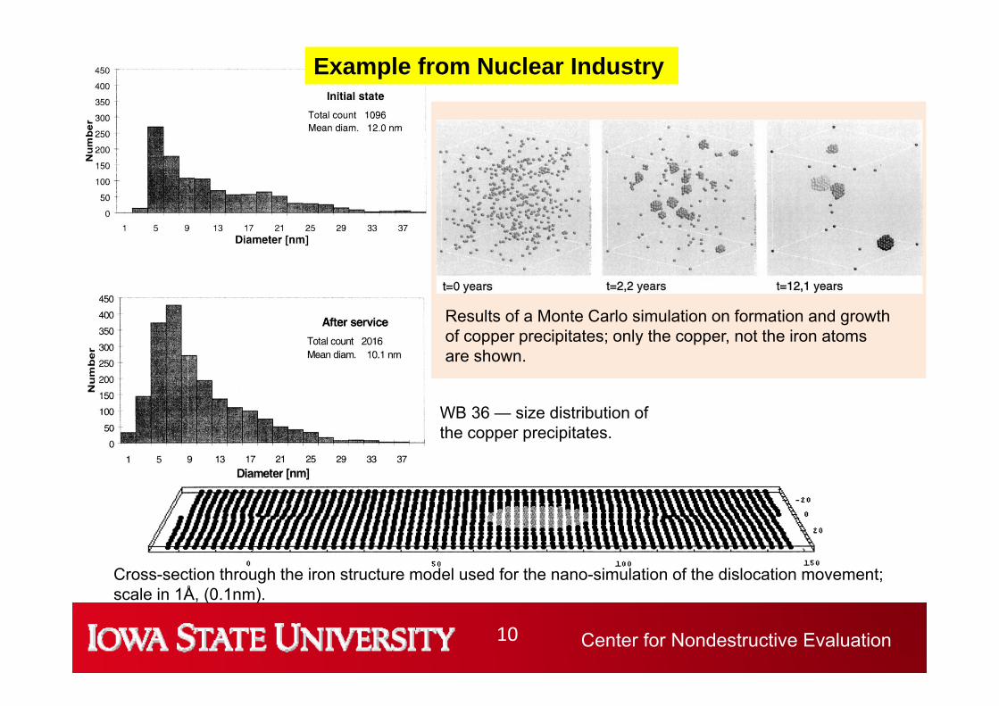
Example from Nuclear Industry
Center for Nondestructive Evaluation10
Results of a Monte Carlo simulation on formation and growth of copper precipitates; only the copper, not the iron atomsare shown.
Cross-section through the iron structure model used for the nano-simulation of the dislocation movement; scale in 1Å, (0.1nm).
WB 36 — size distribution of the copper precipitates.
Example from Nuclear Industry
Center for Nondestructive Evaluation11
2L
PINNING POINTS
MIDDLE PRECIPITATE
Interaction of precipitates with dislocation
Fine phase precipitates Coarse phase precipitatesReference: Edited by J. Hatch, Aluminum: Properties and Physical Metallurgy, American Society for Metals, 1984, p145
Reference: S. Kuhr, A Microstructural Characterization of Aluminum 7075-T6 Treated with the Retrogression and Re-Aging Process
“As part of the normal quality control processes in the A400M fleet we have identified a material issue,” Airbus said in a statement late Friday. “It concerns a previously unknown cracking behavior of an aluminum alloys material. The issue is not impacting flight safety and does not require any immediate measures beyond a program of inspections and repairs that can be incorporated into the normal maintenance and upgrades schedules.”
Center for Nondestructive Evaluation15
That is behind the Cracks in the Airbus FuselageDas steckt hinter den Rissen im Airbus-Rumpf,
Die Welt 26.04.16
• Already in 2011 an AL Zn alloy showed an unknown material behavior. First indication during full scale fatigue test in Dresden
Hinter den Kulissen gibt es aber Aufregung um die Abläufe. So räumt die für den A400M-Bau verantwortliche Rüstungs- und Sicherheitssparte ein, dass bereits 2011 eine Aluminium-Legierung "ein vorher unbekanntes Materialverhalten" zeigte. Da hatte das erste A400M-Modell schon längst seinen Erstflug. In Branchenkreisen ist zu hören, dass 2011 die Auffälligkeiten bei Bauteilen aus modernen Aluminium-Zink-Legierungen bei einem Zeitraffer-Belastungstest am Boden auffielen. Dabei wurde bei einer A400M in einer Testhalle in Dresden ein komplettes Flugzeugleben simuliert.
• The material was approved for application since 2008 Die Experten standen vor einem Rätsel, zumal das Material der Alu-Legierung bereits seit 2008 für den Einsatz zugelassen war. Daher begannen auch ab Herbst 2013 die A400M-Auslieferungen, zuerst an Frankreich. Eingekreist wurde die Risse-Ursache erst zwei Jahre nach dem Belastungstests in Airbus-Laboren in einer ersten Ursachenvermutung.
• Explanation in 2015: Mixture of chemical composition, pressure, stress, temperature (service conditions). It is not corrosion!
Nach weiteren Forschungen und Tests gelang es 2015, eine Erklärung herauszufiltern. Die Rede ist von einem komplexen Mix aus der chemischen Zusammensetzung der Alu-Zink-Legierung und anderen Faktoren wie Druck, Dehnung und Temperatur, kurz Umwelteinflüssen. Laut Airbus handelt es sich nicht um Korrosion.
• The AL Zn alloy will also be used for A 350Im Fokus stehe der Rumpfabschnitt, der die Belastungen der Tragflächen aushalten muss. Bislang sind gut zwei Dutzend A400M-Modelle ausgeliefert. In Luftfahrtkreisen ist zu hören, dass Bauteile aus der umstrittenen Aluminium-Zink-Legierung auch beim neuen Langstreckenmodell A350 zum Einsatz kommen – allerdings im kleinen Maßstab.
• For insiders the A400M material fiasco is a proof for risks (that might result) from the competition for new aircraft materials
Für Branchenkenner ist das A400M-Materialdebakel ein Beleg für die Risiken aus dem Wettbewerb um neue Flugzeugwerkstoffe. Auf der einen Seite stehen die großen Hersteller von Aluminium-Legierungen, wie Alcoa (USA) oder Constellium (Niederlande), die Angst um ihr Geschäft haben, seitdem hochfeste und leichte Kohlefaserwerkstoffe (CFK) in den Flugzeugbau Einzug halten.
Center for Nondestructive Evaluation16
The Material?
EN AW-7030 ; Al Zn5.5Mg1Cu???
• Well known as: Al Zn5.5Mg1Cu AA7075• Can be compared but has higher Copper content• General 7075 characteristics and uses (from Alcoa):The T7351
temper (can be compared to RRA) offers high strength and improved stress-corrosion cracking resistance.
• Applications: Aircraft fittings, gears and shafts, fuse parts, meter shafts and gears, missile parts, regulating valve parts, worm gears, keys, aircraft, aerospace and defense applications; bike frames, all terrain vehicle (ATV) sprockets.
• Mechanical properties and SCC are very sensitive to heat treatment.
Center for Nondestructive Evaluation17
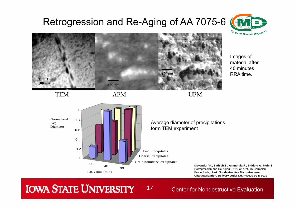
Images of material after 40 minutes RRA time.
2040
60
Grain boundary Precipitates
Coarse PrecipitatesFine Precipitates
0
0.2
0.4
0.6
0.8
1
RRA time (min)
NormalizedAvg.Diameter
Average diameter of precipitations form TEM experiment
Retrogression and Re-Aging of AA 7075-6
Meyendorf N., Sathish S., Ananthula R., Siddoju A., Kuhr S.Retrogression and Re-Aging (RRA) of 7075-T6 Corrosion Prone Parts; Part: Nondestructive Microstructure Characterization, Delivery Order No. F42620-00-D-0039
Center for Nondestructive Evaluation18
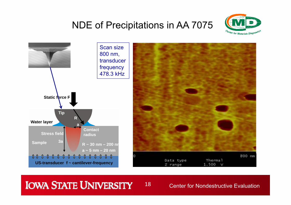
Scan size 800 nm, transducer frequency 478.3 kHz
NDE of Precipitations in AA 7075
Sample
Tip
Water layer
Stress field
3a
Static force F
Contact radius
aR
R ~ 30 nm – 200 nma ~ 5 nm – 20 nm
US-transducer f ~ cantilever-frequency
Center for Nondestructive Evaluation19
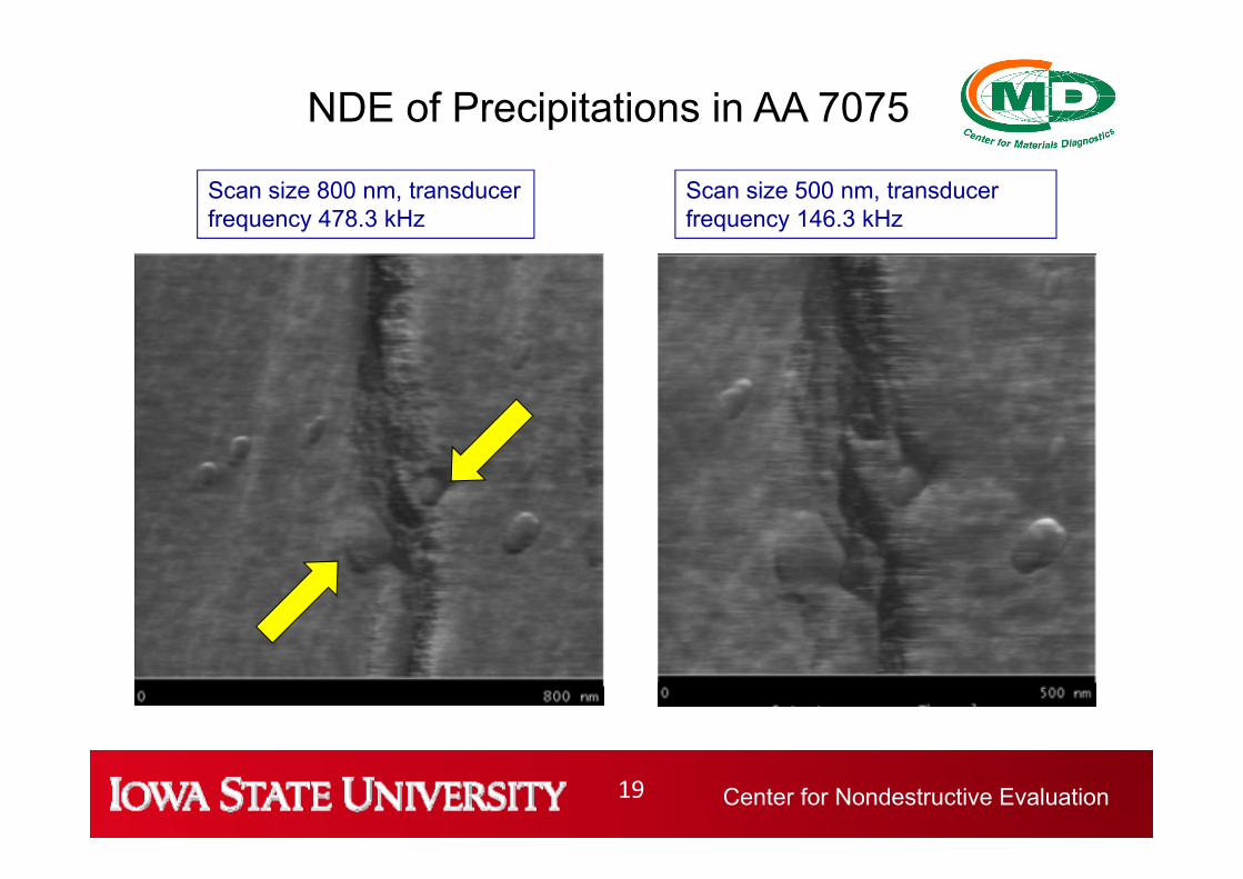
Scan size 800 nm, transducer frequency 478.3 kHz
NDE of Precipitations in AA 7075
Scan size 500 nm, transducer frequency 146.3 kHz
Center for Nondestructive Evaluation20
Conclusion
• New high tech materials might change their designed properties due to service conditions
• Usually modeling and lab tests do not consider these effects
• NDE or continuous monitoring (SHM) will be required even if no fatigue is predicted by the designers of the structure
Center for Nondestructive Evaluation21
Accidents by fatigue• Others• The 1862 Hartley Colliery Disaster was caused by the fracture of a steam engine beam and killed 220 people.• The 1919 Great Molasses Flood has been attributed to a fatigue failure.• The 1948 Northwest Airlines Flight 421 crash due to fatigue failure in a wing spar root• The 1957 "Mt. Pinatubo", presidential plane of Philippine President Ramon Magsaysay, crashed due to engine failure
caused by metal fatigue.• The 1965 capsize of the UK's first offshore oil platform, the Sea Gem, was due to fatigue in part of the suspension system
linking the hull to the legs.• The 1968 Los Angeles Airways Flight 417 lost one of its main rotor blades due to fatigue failure.• The 1968 MacRobertson Miller Airlines Flight 1750 that lost a wing due to improper maintenance leading to fatigue failure• The 1977 Dan-Air Boeing 707 crash caused by fatigue failure resulting in the loss of the right horizontal stabilizer• The 1980 LOT Flight 7 that crashed due to fatigue in an engine turbine shaft resulting in engine disintegration leading to
loss of control• The 1985 Japan Airlines Flight 123 crashed after the aircraft lost its vertical stabilizer due to faulty repairs on the rear
bulkhead.• The 1988 Aloha Airlines Flight 243 suffered an explosive decompression due to fatigue failure.• The 1989 United Airlines Flight 232 lost its tail engine due to fatigue failure in a fan disk hub.• The 1992 El Al Flight 1862 lost both engines on its right-wing due to fatigue failure in the pylon mounting of the #3 Engine.• The 1998 Eschede train disaster was caused by fatigue failure of a single composite wheel.• The 2000 Hatfield rail crash was likely caused by rolling contact fatigue.• The 2002 China Airlines Flight 611 had disintegrated in-flight due to fatigue failure.• The 2005 Chalk's Ocean Airways Flight 101 lost its right wing due to fatigue failure brought about by inadequate
maintenance practices.• The 2009 Viareggio train derailment due to fatigue failure.
The failure of an axle on the wagon that derailed is being investigated as a possible cause.[13][19] Italian Transport Minister Altero Matteoli informed the Italian Parliament on 1 July that a defective axle may have caused the accident.[16]
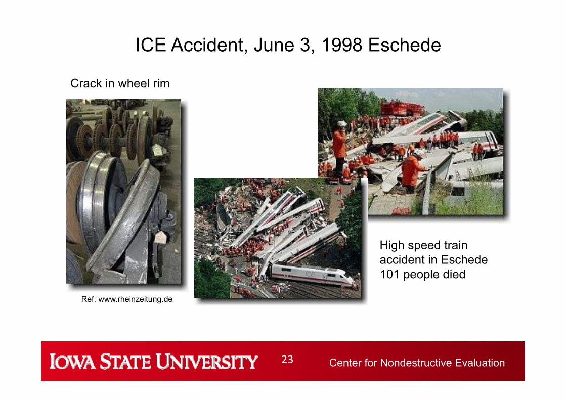
Center for Nondestructive Evaluation23
Ref: www.rheinzeitung.de
Crack in wheel rim
ICE Accident, June 3, 1998 Eschede
High speed train accident in Eschede101 people died
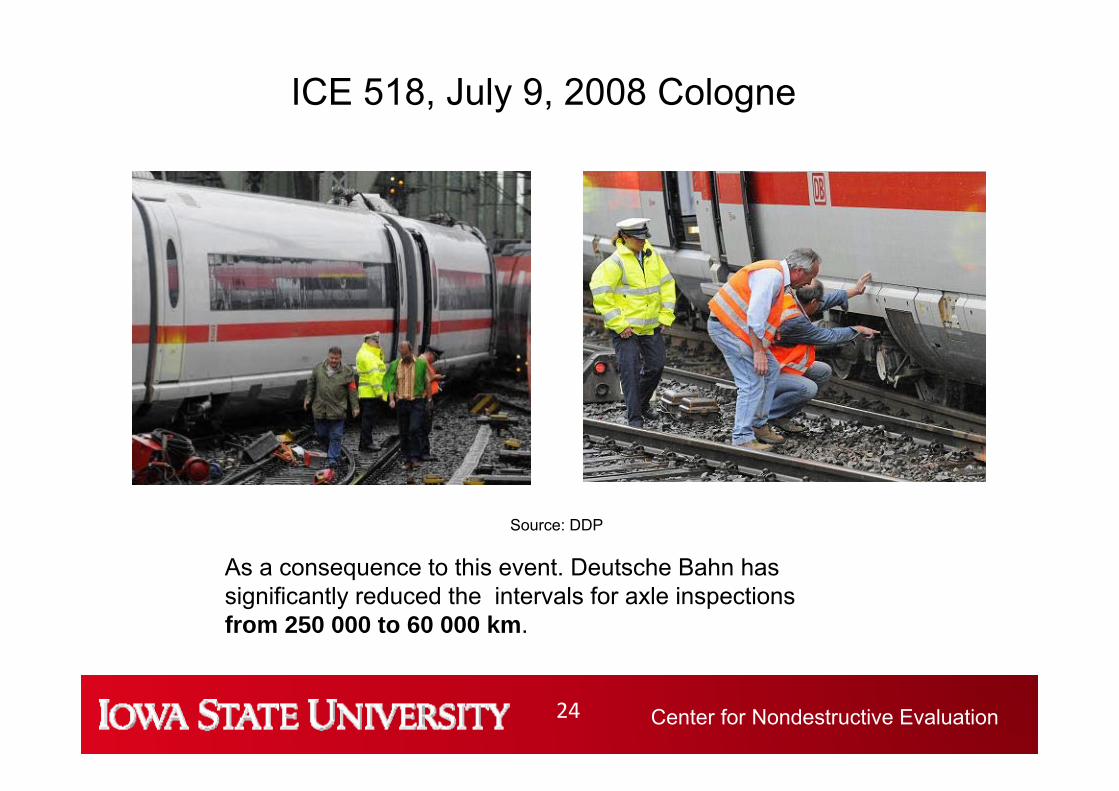
Center for Nondestructive Evaluation24
Source: DDP
ICE 518, July 9, 2008 Cologne
As a consequence to this event. Deutsche Bahn has significantly reduced the intervals for axle inspectionsfrom 250 000 to 60 000 km.
Center for Nondestructive Evaluation25
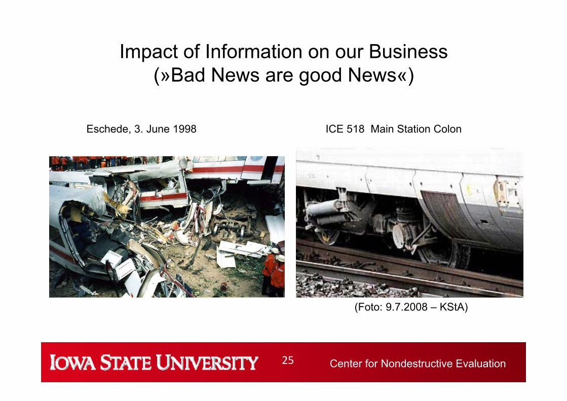
Impact of Information on our Business (»Bad News are good News«)
(Foto: 9.7.2008 – KStA)
ICE 518 Main Station ColonEschede, 3. June 1998
Center for Nondestructive Evaluation26
Why is this happening??
Material Properties are known Loading conditions are knownModelling of the structure is doneTesting for all structural dimensions performed
Usually coincidence of undetected defect(s) (inclusion, pores) and cyclic loading
Deutsche Bahn has significantly reduced the intervals for axle inspections from 250,000 to 60,000 km as a consequence of the Accident in Cologne
On Train Wheel set inspection system
Mobile Hollow Axle Testing System
Center for Nondestructive Evaluation29
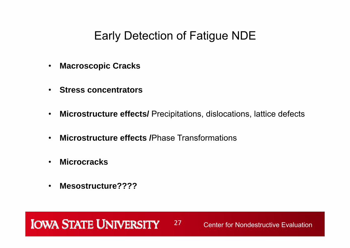
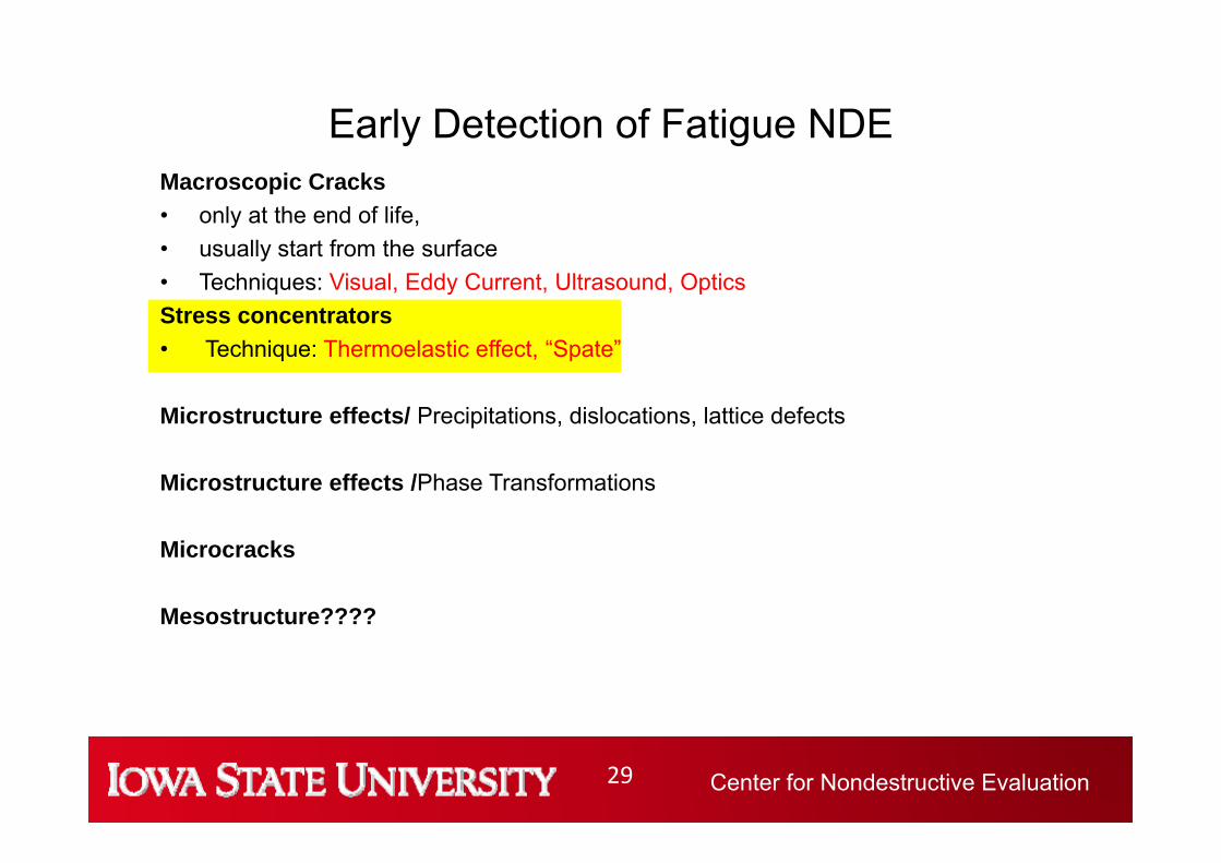
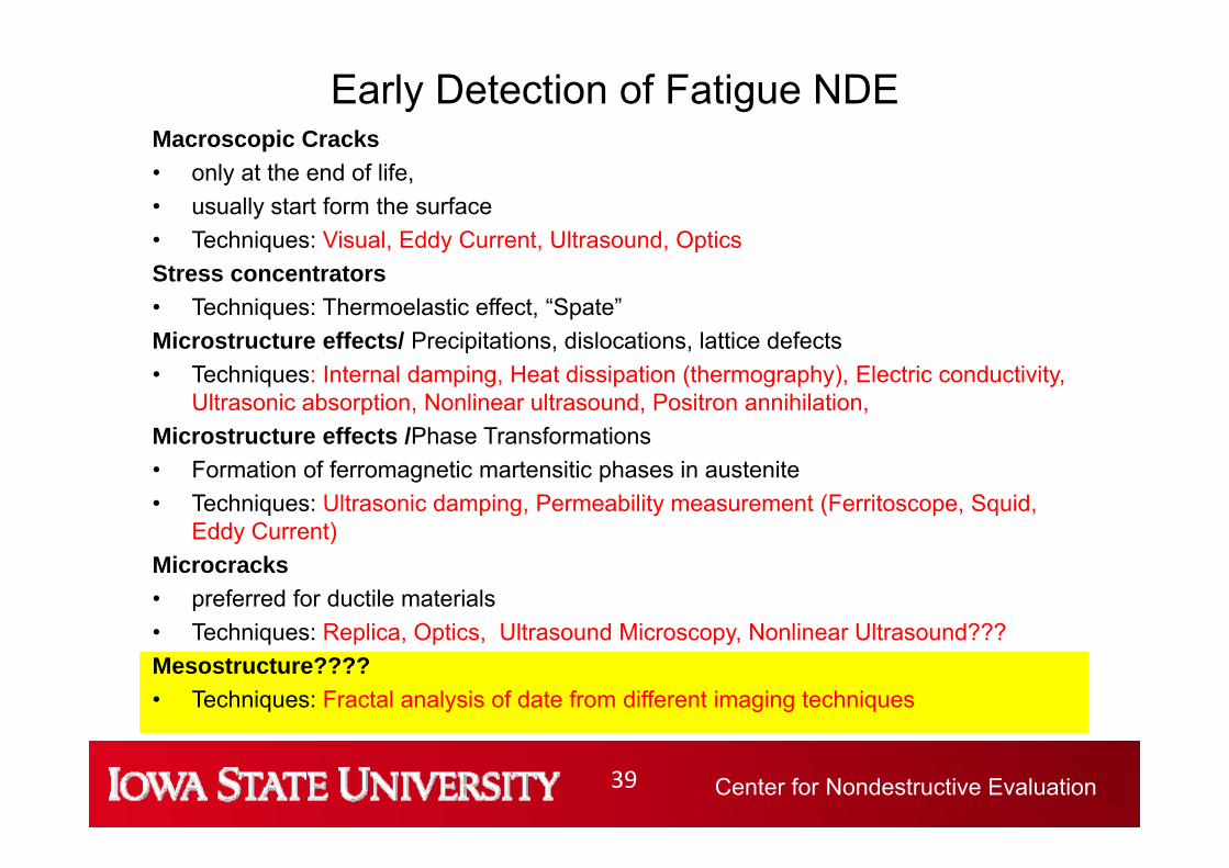
Early Detection of Fatigue NDEMacroscopic Cracks• only at the end of life, • usually start from the surface• Techniques: Visual, Eddy Current, Ultrasound, Optics Stress concentrators • Technique: Thermoelastic effect, “Spate”
Thermoelastic Effect DeltaTherm 1000 image of the stresses in a chain link loaded at 10Hz. Image acquisition time: 30s. Courtesy Stress Photonics, Madison, WI.
T
t
TT0
t
Center for Nondestructive Evaluation31
Early Detection of Fatigue NDEMacroscopic Cracks• only at the end of life, • usually start form the surface• Techniques: Visual, Eddy Current, Ultrasound, Optics Stress concentrators • Technique: Thermoelastic effect, “Spate”Microstructure effects/ Precipitations, dislocations, lattice defects• Techniques: Internal damping, Heat dissipation (thermography), Electric conductivity,
MEASUREMENT OF INTERNAL DAMPING30 Hz 20 kHz 10 MHz
Center for Nondestructive Evaluation35
Early Detection of Fatigue NDEMacroscopic Cracks• only at the end of life, • usually start form the surface• Techniques: Visual, Eddy Current, Ultrasound, Optics Stress concentrators• Techniques: Thermoelastic effect, “Spate”Microstructure effects/ Precipitations, dislocations, lattice defects• Techniques: Internal damping, Heat dissipation (thermography), Electric conductivity,
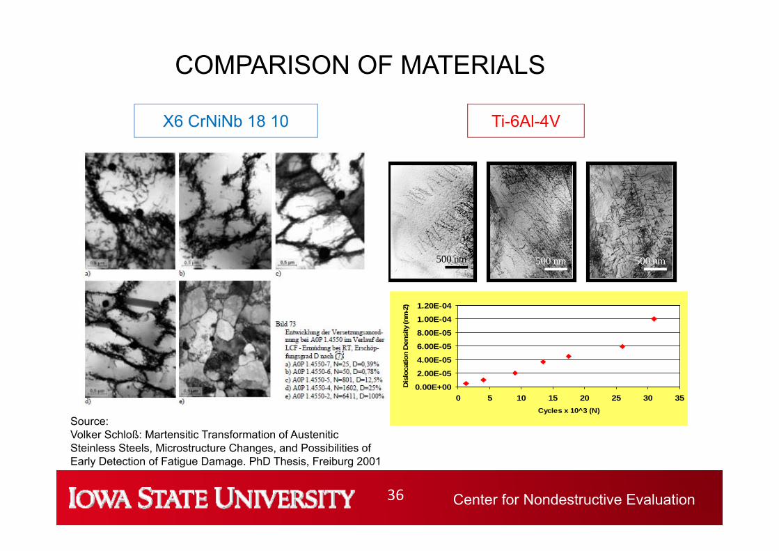
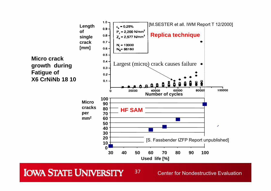
Source:Volker Schloß: Martensitic Transformation of Austenitic Steinless Steels, Microstructure Changes, and Possibilities of Early Detection of Fatigue Damage. PhD Thesis, Freiburg 2001
Center for Nondestructive Evaluation37
0102030405060708090
100
30 40 50 60 70 80 90 100Used life [%]
Microcrackspermm2
HF SAM
[S. Fassbender IZFP Report unpublished]
Number of cycles
Length ofsingle crack[mm]
Replica technique
Largest (micro) crack causes failure
[M.SESTER et all. IWM Report T 12/2000]
Micro crack growth during Fatigue ofX6 CrNiNb 18 10
Center for Nondestructive Evaluation38
Cra
ck le
ngth
Consumed Fatigue Life
Ti-6Al-4V
X6 CrNiNb 18 10
Limit for NDE Detection
0 100 %
Dis
loca
tion
dens
ity
Formation of subgrains
X6 CrNiNb 18 10Ti-6Al-4V
COMPARISON OF MATERIALS
Center for Nondestructive Evaluation39
Early Detection of Fatigue NDEMacroscopic Cracks• only at the end of life, • usually start form the surface• Techniques: Visual, Eddy Current, Ultrasound, Optics Stress concentrators• Techniques: Thermoelastic effect, “Spate”Microstructure effects/ Precipitations, dislocations, lattice defects• Techniques: Internal damping, Heat dissipation (thermography), Electric conductivity,
Eddy Current)Microcracks• preferred for ductile materials• Techniques: Replica, Optics, Ultrasound Microscopy, Nonlinear Ultrasound???Mesostructure???? • Techniques: Fractal analysis of date from different imaging techniques
Center for Nondestructive Evaluation40
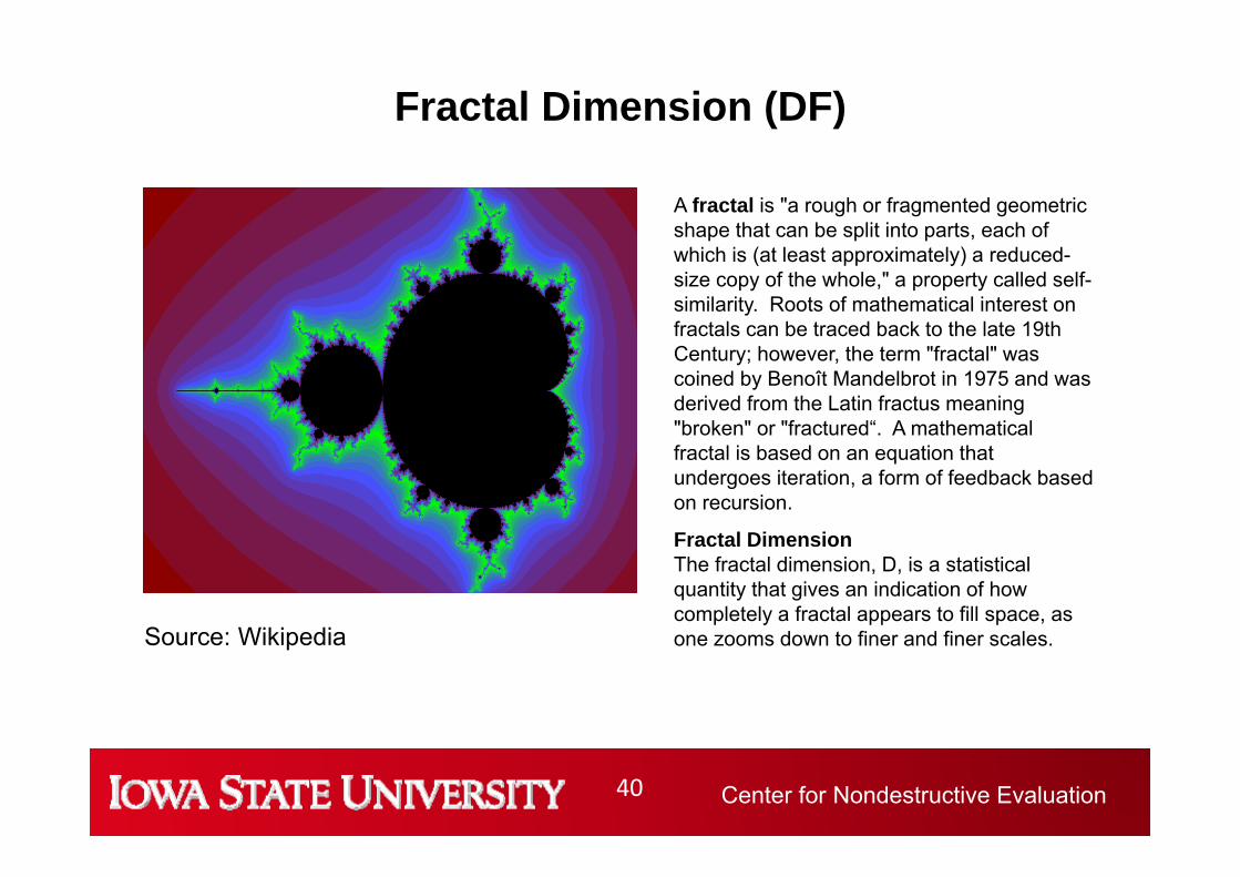
Fractal Dimension (DF)
A fractal is "a rough or fragmented geometric shape that can be split into parts, each of which is (at least approximately) a reduced-size copy of the whole," a property called self-similarity. Roots of mathematical interest on fractals can be traced back to the late 19th Century; however, the term "fractal" was coined by Benoît Mandelbrot in 1975 and was derived from the Latin fractus meaning "broken" or "fractured“. A mathematical fractal is based on an equation that undergoes iteration, a form of feedback based on recursion.
Fractal DimensionThe fractal dimension, D, is a statistical quantity that gives an indication of how completely a fractal appears to fill space, as one zooms down to finer and finer scales. Source: Wikipedia
Center for Nondestructive Evaluation41
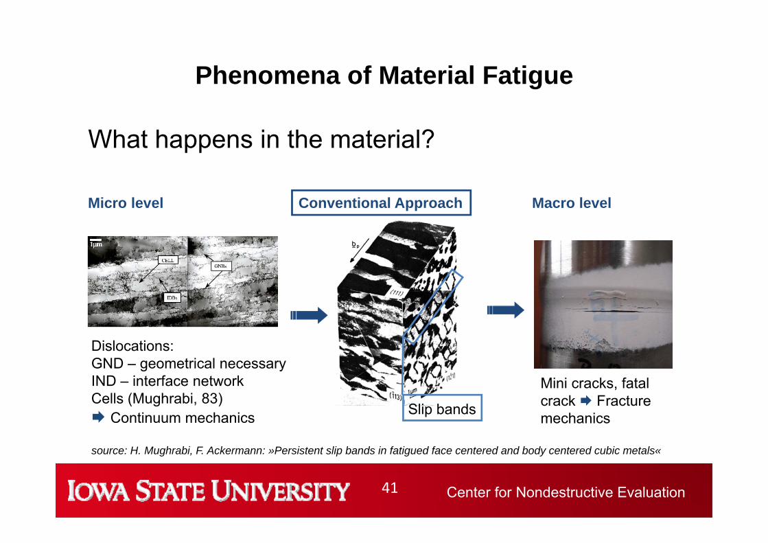
Phenomena of Material Fatigue
What happens in the material?
source: H. Mughrabi, F. Ackermann: »Persistent slip bands in fatigued face centered and body centered cubic metals«
Mini cracks, fatal crack Fracture mechanicsSlip bands
Conventional Approach
Center for Nondestructive Evaluation42
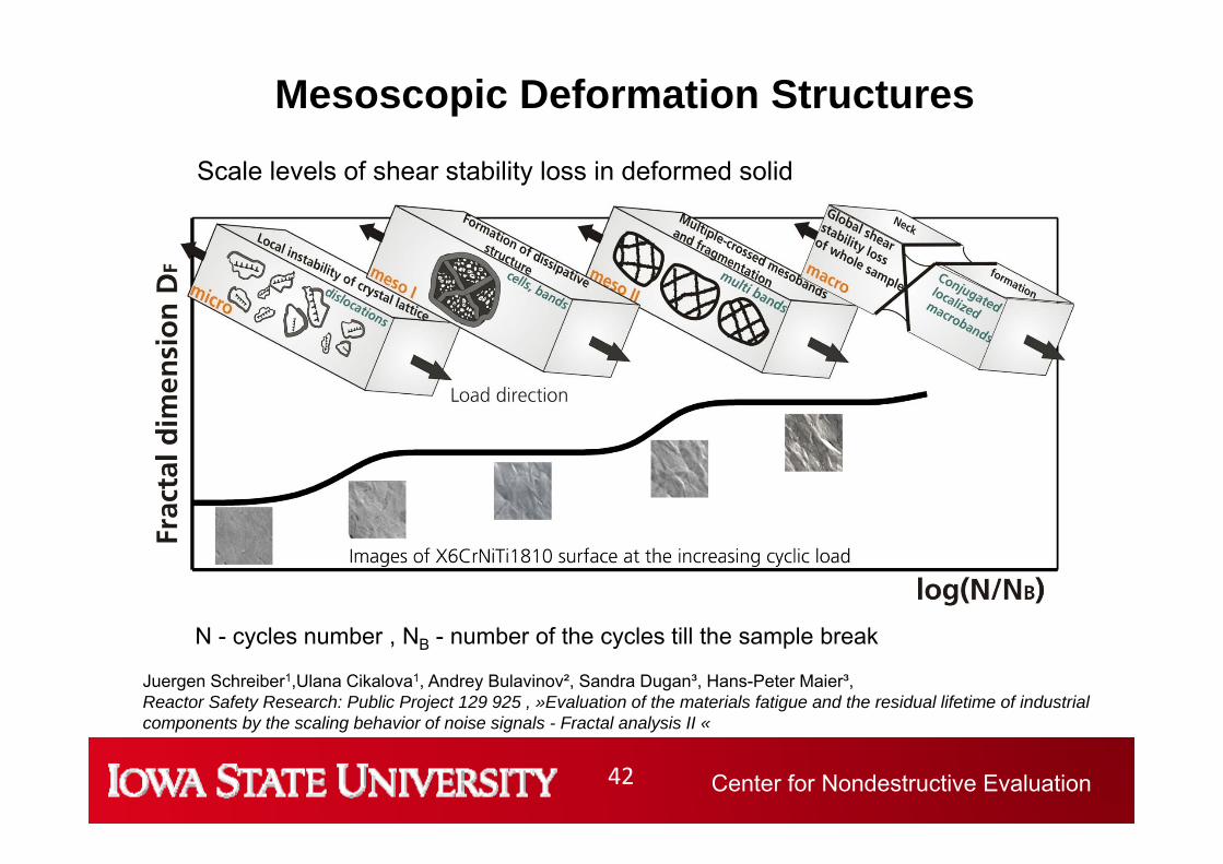
Mesoscopic Deformation Structures
N - cycles number , NB - number of the cycles till the sample break
Juergen Schreiber1,Ulana Cikalova1, Andrey Bulavinov², Sandra Dugan³, Hans-Peter Maier³,Reactor Safety Research: Public Project 129 925 , »Evaluation of the materials fatigue and the residual lifetime of industrial components by the scaling behavior of noise signals - Fractal analysis II «
Scale levels of shear stability loss in deformed solid
Center for Nondestructive Evaluation43
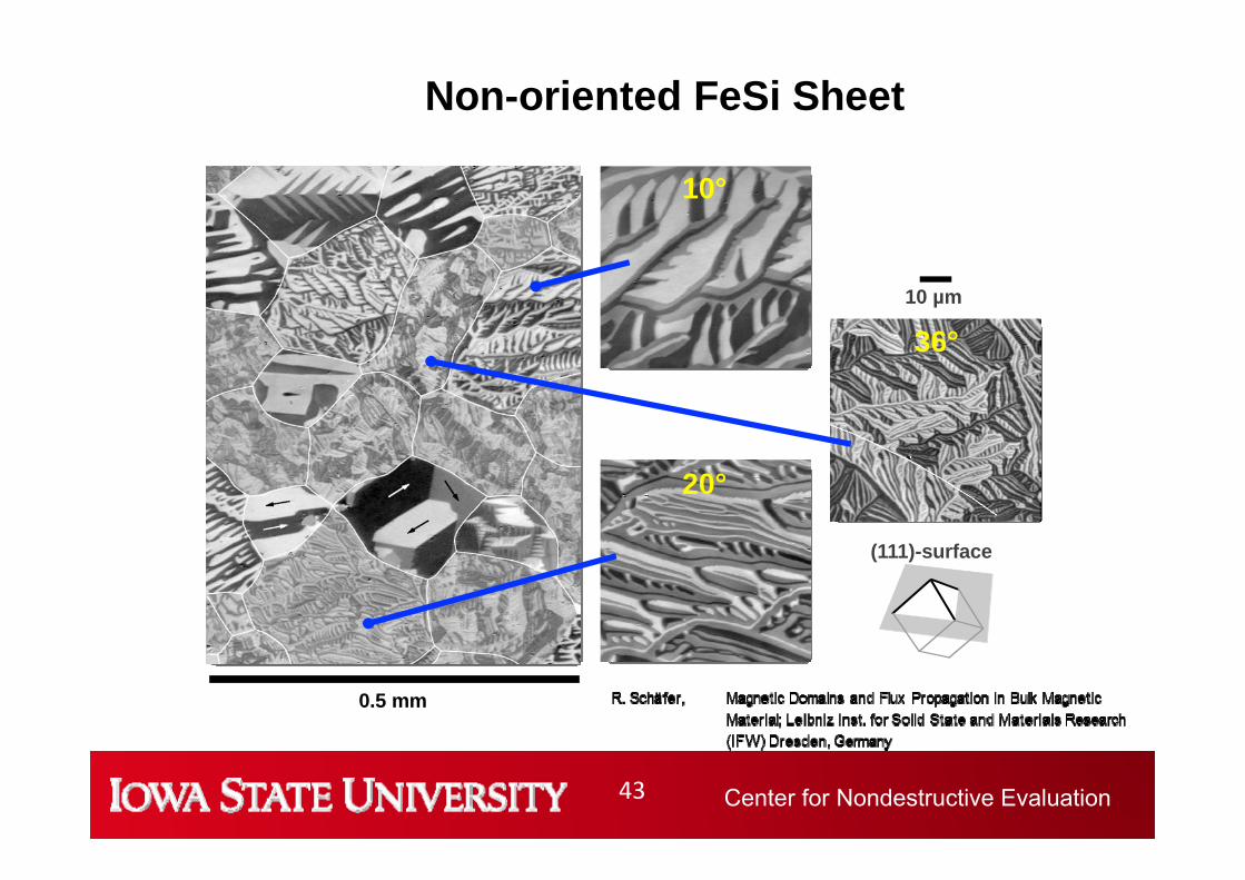
0.5 mm
10 µm
36°
(111)-surface
10°
20°
Non-oriented FeSi Sheet
Center for Nondestructive Evaluation44
0
1
2
3
4
5
6
8
10
12
-4
-2
0
2
4
RMS
Y-Ach
se [c
m]
X-Achse [cm]
Barkhausen Map of Fatigued CT Sample22 NiMoCr 37
0
1
2
3
4
5
1.1
1.2
1.3
1.4
1.5
-4
-2
0
2
4
Fractal dimension D
F
Y-Ach
se [c
m]
X-Achse [cm]
RMS ~ Residual Stress Fractal Dimension
Crack
Center for Nondestructive Evaluation45
Fatigue in Composite Materials
• In metals the nucleation and growth of damage is well understood.
• Many decades of experience exist
• For composite materials damage nucleation and growth is still a matter of research
• Practical experience for material behavior under service conditions is limited
• For these materials NDE Techniques can help to examine degradation processes
Center for Nondestructive Evaluation46 46
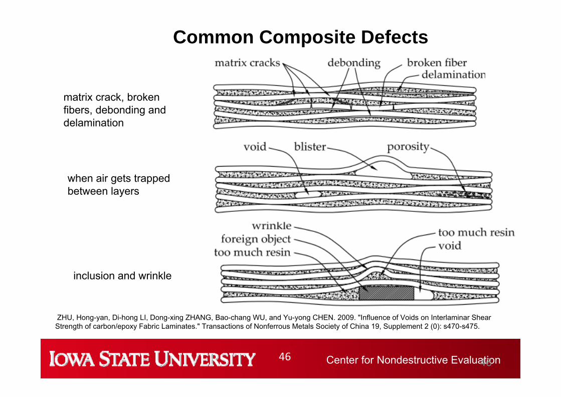
inclusion and wrinkle
Common Composite Defects
matrix crack, broken fibers, debonding and delamination
when air gets trapped between layers
ZHU, Hong-yan, Di-hong LI, Dong-xing ZHANG, Bao-chang WU, and Yu-yong CHEN. 2009. "Influence of Voids on Interlaminar ShearStrength of carbon/epoxy Fabric Laminates." Transactions of Nonferrous Metals Society of China 19, Supplement 2 (0): s470-s475.
Center for Nondestructive Evaluation47 47
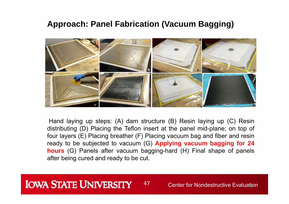
Approach: Panel Fabrication (Vacuum Bagging)
Hand laying up steps: (A) dam structure (B) Resin laying up (C) Resindistributing (D) Placing the Teflon insert at the panel mid-plane; on top offour layers (E) Placing breather (F) Placing vacuum bag and fiber and resinready to be subjected to vacuum (G) Applying vacuum bagging for 24hours (G) Panels after vacuum bagging-hard (H) Final shape of panelsafter being cured and ready to be cut.
Center for Nondestructive Evaluation48
Characterization Methods Applied
Imaging Techniques• X-ray Imaging and Laminography (BAM)• UT Volume Scans (TU Dresden and AMIC GmbH)• HF Eddy Current (IKTS)• Pulsed- and Pulsed Phase Thermography (NanoTest GmbH)• Look in Thermography (NanoTest GmbH)
Integral Characterization Methods• Thermal Conductivity (NanoTest GmbH)• X-ray Refraction (BAM)
Destructive Techniques• Serial Sectioning (Univ. Dayton)• Fatigue Test (Univ. Dayton)
Center for Nondestructive Evaluation49
ThermographyNanoTest GmbH
50 MHz UTTU Dresden
7 MHz ECIKTS
X‐ray binaryX‐ray
Comparison of Images for the Similar Coupon
BAM
Center for Nondestructive Evaluation50
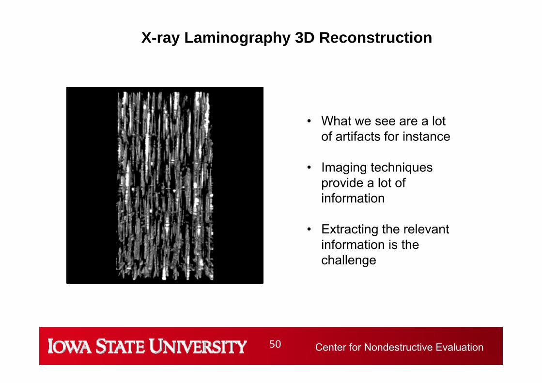
X-ray Laminography 3D Reconstruction
• What we see are a lot of artifacts for instance
• Imaging techniques provide a lot of information
• Extracting the relevant information is the challenge
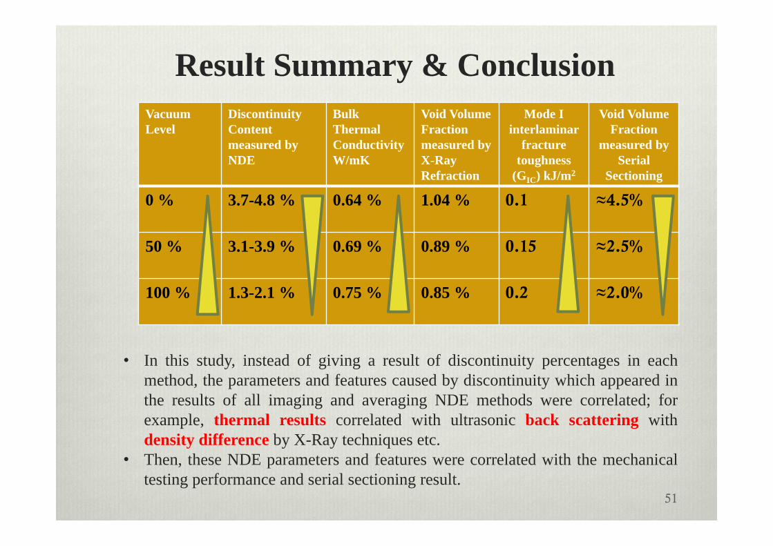
Result Summary & ConclusionVacuum Level
Discontinuity Contentmeasured by NDE
Bulk Thermal Conductivity W/mK
Void Volume Fraction measured by X-Ray Refraction
Mode I interlaminar
fracture toughness
(GIC) kJ/m2
Void Volume Fraction
measured by Serial
Sectioning
0 % 3.7-4.8 % 0.64 % 1.04 % 0.1 ≈4.5%
50 % 3.1-3.9 % 0.69 % 0.89 % 0.15 ≈2.5%
100 % 1.3-2.1 % 0.75 % 0.85 % 0.2 ≈2.0%
51
• In this study, instead of giving a result of discontinuity percentages in eachmethod, the parameters and features caused by discontinuity which appeared inthe results of all imaging and averaging NDE methods were correlated; forexample, thermal results correlated with ultrasonic back scattering withdensity difference by X-Ray techniques etc.
• Then, these NDE parameters and features were correlated with the mechanicaltesting performance and serial sectioning result.
Center for Nondestructive Evaluation52
Not a Summary
• NDE can provide a lot of useful (or useless) data about the structure, loading conditions, and health of a material or component.
• However, it is very unlikely that only by processing of NDE data and combining this with any kind of modelling reliable life predictions are successful, due to the complexity of design, material structure, and real world loading conditions (combines mechanical, thermal, chemical…).
• After decades of research worldwide we don’t have applicable solutions for metallic components, for composites the situation is even more complex.
• The worst case will be additive manufacturing, where uncertainties in the printing process and the resulting microstructure arise.
Center for Nondestructive Evaluation53
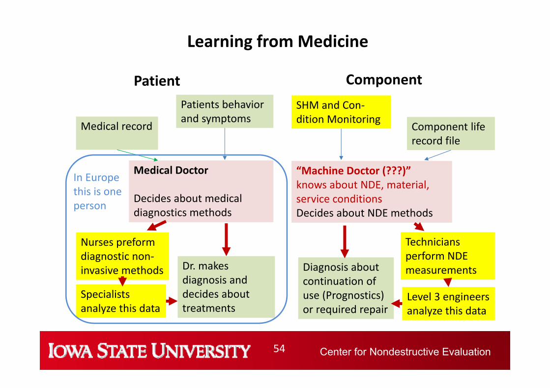
We need a new way of thinking in NDE
The traditional NDE philosophy:
=> One Component, One Inspector, One Instrument, Decisions based on rules and standards,will not satisfy future challenges where we theoretically print a complete aircraft.
We shall learn from medicine how to be successful in the future.
Center for Nondestructive Evaluation54
Learning from Medicine
Patient
Medical record
Patients behavior and symptoms
Medical Doctor
Decides about medical diagnostics methods
Nurses preform diagnostic non‐invasive methods Dr. makes
diagnosis and decides about treatments
Specialists analyze this data
Component
Component life record file
SHM and Con‐dition Monitoring
Technicians perform NDE measurementsDiagnosis about
continuation of use (Prognostics) or required repair
“Machine Doctor (???)” knows about NDE, material, service conditionsDecides about NDE methods
Level 3 engineers analyze this data
In Europethis is oneperson
Center for Nondestructive Evaluation55
Conclusion• Todays technology provides us with excellent measurement tools, affordable,
simple to handle, and high performance that we can access from everywhere, but we have to know what data we need and how to analyze.
• The Internet allows to use specialists worldwide to discuss results and decisions, but we have to know whom to ask.
• Powerful modeling tools make us believe that we can understand everything, but it is all based on assumptions.
• What we need to face future challenges in a world of composites, 3D printed components, smart structures and materials, and infinite data and information is a:
“Machine Doctor” who knows about the potential of NDE methods but also the materials structure and properties, design concept and service


![POTENTIALINDUZIERTE DEGRADATION (PID ... - tuv.com · 1200 Rp [:] Time [min] PIDcon Test - Encapsulant 1 PIDcon Test ... Modultests haben SEMI Task-Force “PV Material Degradation”](https://static.unterlagen.site/doc/80x56/5b145c627f8b9a397c8cb2e5/potentialinduzierte-degradation-pid-tuvcom-1200-rp-time-min-pidcon.jpg)


