UPnP and DPWS Differences and Similarities Seminar zur Erlangung des akademischen Grades Bachelor of Science im Rahmen des Studiums Medieninformatik eingereicht von Stefan Reichhard Matrikelnummer 0208213 an der Fakultät für Informatik der Technischen Universität Wien Betreuung: Ao.Univ.-Prof. Dr. Wolfgang Kastner Mitwirkung: Wien, 04.11.2013 (Unterschrift Verfasser) (Unterschrift Betreuung) Technische Universität Wien A-1040 Wien Karlsplatz 13 Tel. +43-1-58801-0 www.tuwien.ac.at
Transcript
UPnP and DPWS
Differences and Similarities
Seminar
zur Erlangung des akademischen Grades
Bachelor of Science
im Rahmen des Studiums
Medieninformatik
eingereicht von
Stefan ReichhardMatrikelnummer 0208213
an derFakultät für Informatik der Technischen Universität Wien
Betreuung: Ao.Univ.-Prof. Dr. Wolfgang KastnerMitwirkung:
Technische Universität WienA-1040 Wien � Karlsplatz 13 � Tel. +43-1-58801-0 � www.tuwien.ac.at
Erklärung zur Verfassung der Arbeit
Stefan ReichhardNeustiftgasse 15/11, 1070 Wien
Hiermit erkläre ich, dass ich diese Arbeit selbständig verfasst habe, dass ich die verwende-ten Quellen und Hilfsmittel vollständig angegeben habe und dass ich die Stellen der Arbeit -einschließlich Tabellen, Karten und Abbildungen -, die anderen Werken oder dem Internet imWortlaut oder dem Sinn nach entnommen sind, auf jeden Fall unter Angabe der Quelle als Ent-lehnung kenntlich gemacht habe.
UPnP is an acronym for Universal Plug and Play. UPnP is one of the first attempts to define anarchitecture which can fulfil a zero-configuration scenario for a different set of devices. In itsearly days, it was a technology developed by Microsoft and embedded in its operating systemWindows. In 1999, a forum was established, nowadays consisting of more than 900 companieswho are industry leaders in a great variation of different sectors (e.g. consumer electronics,computing, home automation, mobile devices) to define UPnP.
UPnP is more than just a simple extension of the Plug and Play peripheral model. A UPnPenabled device can dynamically join a network (and obtain all necessary information like an IPaddress), announce itself and its capabilities to the (UPnP) network, and learn about the presenceand capabilities of other devices currently connected to the same network. It does so with trulyzero configuration, the only thing a user has to do is to plug in the device into the network.Devices can subsequently communicate with each other directly, thereby further enabling peerto peer networking.
Universal Plug and Play utilizes a well-known protocol stack, which is tested for many years.The protocols included are IP, TCP, UDP, HTTP and XML. Because of this it is quite easy andstable to expand an existing network with the capabilities of UPnP. Relying on protocols insteadof Application Programming Interfaces (API) makes the UPnP architecture also independentfrom any given operating system and also from a specific programming language [1].
1.2 Use Case
Within this thesis, use cases will be combined to demonstrate the power of a UPnP enabledhousehold.
Imagine your UPnP alarm clock or even your stereo or TV wakes you up one hour earlierthan ordinary, just because you have added an important meeting in your personal UPnP enabled
1
calendar the day before. This meeting record has created a UPnP notification. The alarm clockwas listening to it and adjusted the wake up time accordingly. Also, the HVAC system wasinterested in this notification and uses the new alarm time to adjust the set-point temperatureaccordingly, so you will not freeze when you getting up. When you leave the house you push the“away”-switch resulting in turning off all lights, TVs, stereos and switching the HVAC systemto “away”-mode.
At work the meeting went well and your boss gives you some days off. On the web-browseryou set the vacation flag for the next day.
Later the day, when you are back home you decide to watch a movie. On a control deviceyou select “theatre”-mode, and all involved devices will respond immediately (the lights willdim down, the window blinds lower, the receiver will turn on and select the corresponding input,and last but not least, the TV will be turned on as well). You are able to enjoy the cinema feelingwithout the hassle of setup this scenario manually.
The next day you leave town with a couple of friends. You already set the vacation flagthe day before via Internet, so during your absence your house is not quiet at all; it is actingautonomously for different reasons that may include:
• periodically turning on and off the lights on a random pattern to simulate you are still athome (security)
• lowering the heat or turning it off (energy saving)
• recording your favorite shows, so you can watch it later (comfort)
All this can be done with UPnP enabled devices and some scripts to automate different scenarioslike “theatre”-, “vacation”- or “away”-mode.
1.3 Components of a UPnP Network
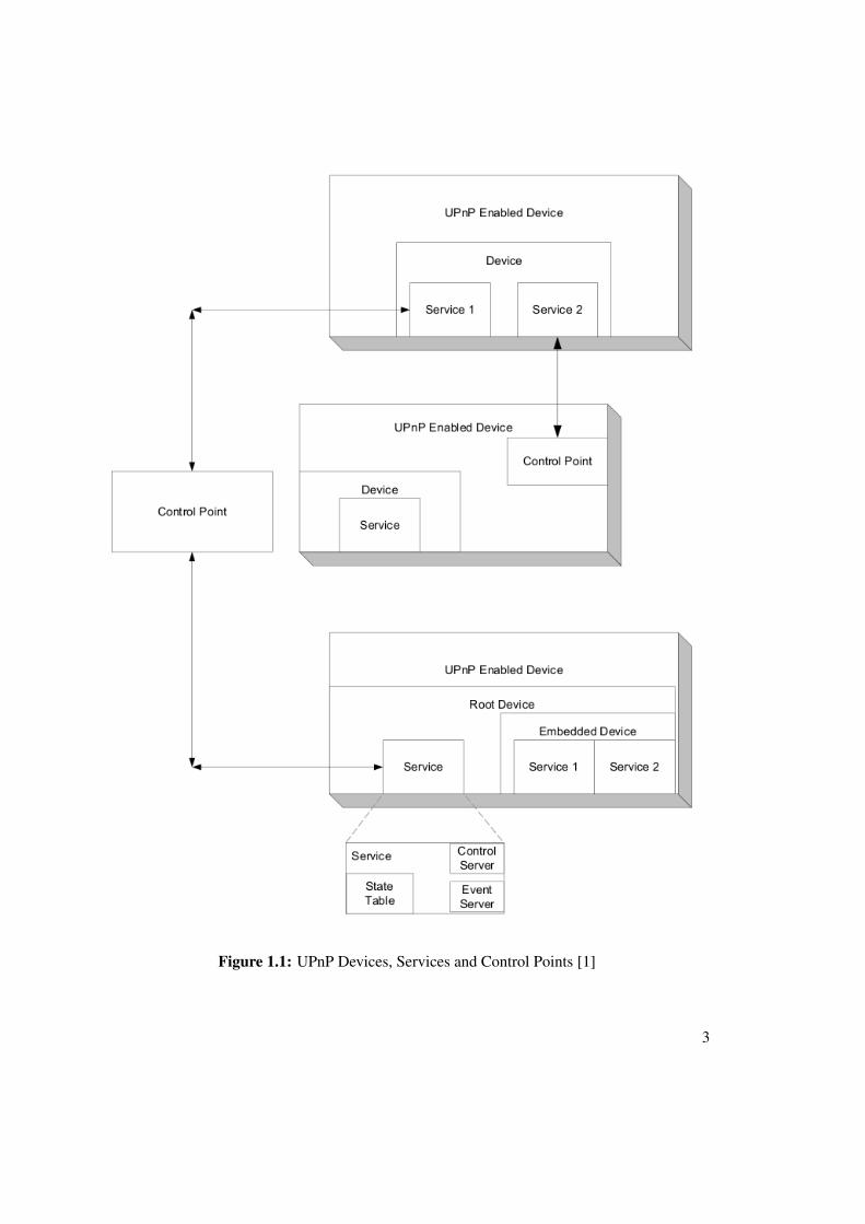
A UPnP network consists of 3 major components. These are devices, services and control points.In Figure 1.1, a quick overview is given on how the structure of a UPnP network looks like.
UPnP Device
A UPnP device acts like a container of services, nested services and control points. For instance,a Personal Video Recorder (PVR) could be such a device, with an integrated tuner service,playback service and a clock service. These services may differ widely depending on the device.Thus, a printer will implement other services as an Internet gateway or the earlier mentionedPVR device. Hence, it is the goal of different working groups to standardize the correspondingset of services that a particular device type will provide. The resulting device description isrepresented in Extended Markup Language (XML).
2
Figure 1.1: UPnP Devices, Services and Control Points [1]
3
UPnP Service
A service is the elementary part of a UPnP network. The task of a service is to expose its actions,and modelling its state with state variables. You may argue it has similarities with a Java class(it encapsulates actions/methods and holds its public or private state variables). Like the devicedescription, the service description is also represented in XML.
Every service will contain a state table, a control server and an event server. The state tableholds the state information of a service and will update its variables when appropriate. Thecontrol server executes actions when receiving an action request, updates the state table andreturns responses to the caller. The event server will notify any interested subscriber every timethe state changes.
UPnP Control Point
Like the name might suggest, the purpose of a control point is to discover and control otherdevices via their services. The workflow is like following:
• retrieve the device description of devices in a UPnP network and get a list of encapsulatedservices
• retrieve service descriptions and remember the interesting ones
• invoke actions on the services to control the device
• make a subscription to the event server, so the control point will be notified every time thestate changes
1.4 Concept of a UPnP Network
To define how the basic components of a UPnP network work together, different UPnP phaseswere introduced. They specify a basic pattern, a workflow, each UPnP device utilizes to providethe basic communication between them. These phases are named like following:
• Addressing
• Description
• Discovery
• Control
• Eventing
• Presentation
The phases will be described in more detail shortly. The protocols used for communication inthese stages will be listed before.
4
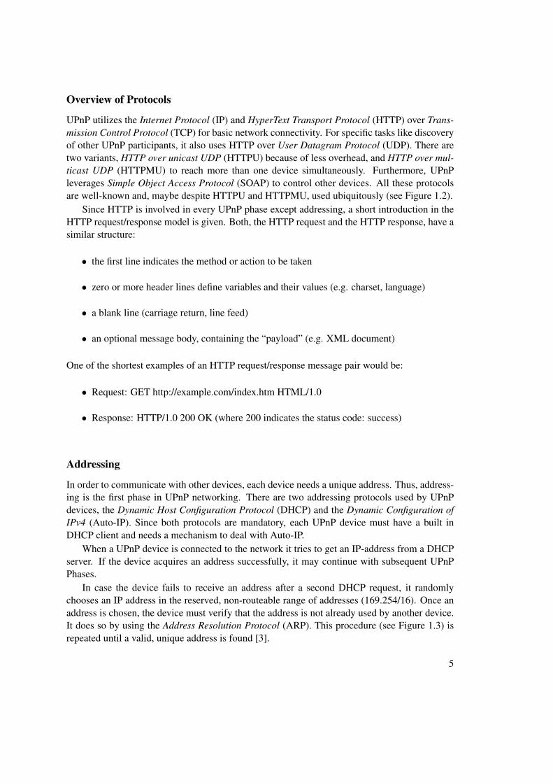
Overview of Protocols
UPnP utilizes the Internet Protocol (IP) and HyperText Transport Protocol (HTTP) over Trans-mission Control Protocol (TCP) for basic network connectivity. For specific tasks like discoveryof other UPnP participants, it also uses HTTP over User Datagram Protocol (UDP). There aretwo variants, HTTP over unicast UDP (HTTPU) because of less overhead, and HTTP over mul-ticast UDP (HTTPMU) to reach more than one device simultaneously. Furthermore, UPnPleverages Simple Object Access Protocol (SOAP) to control other devices. All these protocolsare well-known and, maybe despite HTTPU and HTTPMU, used ubiquitously (see Figure 1.2).
Since HTTP is involved in every UPnP phase except addressing, a short introduction in theHTTP request/response model is given. Both, the HTTP request and the HTTP response, have asimilar structure:
• the first line indicates the method or action to be taken
• zero or more header lines define variables and their values (e.g. charset, language)
• a blank line (carriage return, line feed)
• an optional message body, containing the “payload” (e.g. XML document)
One of the shortest examples of an HTTP request/response message pair would be:
• Request: GET http://example.com/index.htm HTML/1.0
• Response: HTTP/1.0 200 OK (where 200 indicates the status code: success)
Addressing
In order to communicate with other devices, each device needs a unique address. Thus, address-ing is the first phase in UPnP networking. There are two addressing protocols used by UPnPdevices, the Dynamic Host Configuration Protocol (DHCP) and the Dynamic Configuration ofIPv4 (Auto-IP). Since both protocols are mandatory, each UPnP device must have a built inDHCP client and needs a mechanism to deal with Auto-IP.
When a UPnP device is connected to the network it tries to get an IP-address from a DHCPserver. If the device acquires an address successfully, it may continue with subsequent UPnPPhases.
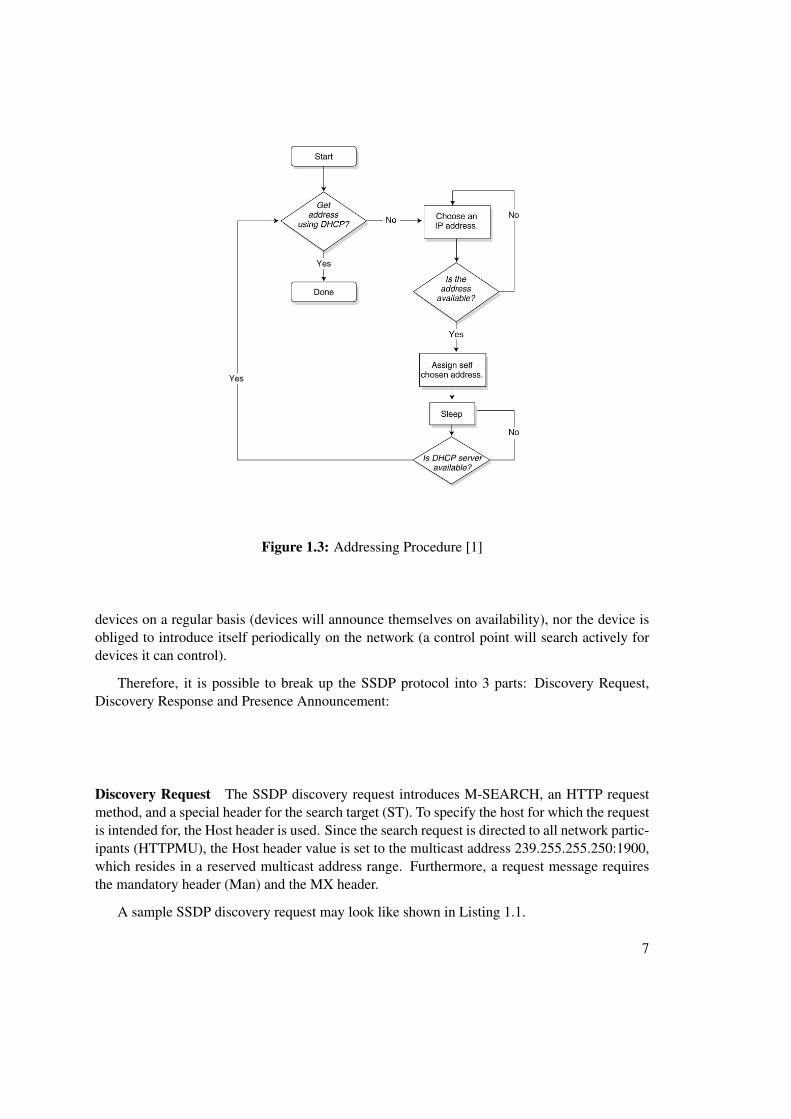
In case the device fails to receive an address after a second DHCP request, it randomlychooses an IP address in the reserved, non-routeable range of addresses (169.254/16). Once anaddress is chosen, the device must verify that the address is not already used by another device.It does so by using the Address Resolution Protocol (ARP). This procedure (see Figure 1.3) isrepeated until a valid, unique address is found [3].
5
Figure 1.2: UPnP Protocol Stack
Discovery
After acquiring an address, a UPnP device is ready to propagate its capabilities in form of ser-vices to control points. Discovery also allows control points to actively search for (distinct)devices and services on the network.
The Simple Service Discovery Protocol (SSDP), a discovery solution for HTTP-based re-sources on the local area network, is used for this purpose. It is designed to be simple anddoesn’t require any configuration, management or administration by the user.
SSDP leverages a subset of ordinary HTTP communication in conjunction with some specialheaders, required for the discovery process.
To save network bandwidth, the SSDP protocol uses a combination of actively searching re-sources on the network (SSDP request/response) as well as an automatic presence announcementmechanism. Whenever a device gets online and after obtaining an address, it sends a multicastmessage (a presence announcement) to introduce itself on the network. A control point sends aSSDP requests to know what devices are available, respectively.
This combination of SSDP request/response and presence announcement is very effectivein a distributed network without central intelligence. All devices have the same knowledgeabout the UPnP members without the necessity for a control point to search the network for new
6
Figure 1.3: Addressing Procedure [1]
devices on a regular basis (devices will announce themselves on availability), nor the device isobliged to introduce itself periodically on the network (a control point will search actively fordevices it can control).
Therefore, it is possible to break up the SSDP protocol into 3 parts: Discovery Request,Discovery Response and Presence Announcement:
Discovery Request The SSDP discovery request introduces M-SEARCH, an HTTP requestmethod, and a special header for the search target (ST). To specify the host for which the requestis intended for, the Host header is used. Since the search request is directed to all network partic-ipants (HTTPMU), the Host header value is set to the multicast address 239.255.255.250:1900,which resides in a reserved multicast address range. Furthermore, a request message requiresthe mandatory header (Man) and the MX header.
A sample SSDP discovery request may look like shown in Listing 1.1.
7
Type of Search Syntax DescriptionAll devices ssdp:all Search for all UPnP devices.
Root devices upnp:rootdevice Only root devices will respond; embeddeddevices will not.
Specific device uuid:device-uuid Search for a particular device by thedevice’s unique ID. The unique ID is
supplied by the device vendor.Devices of aspecific type
urn:schemas-upnp-org:device:deviceType:version
The device type is defined by a workingcommittee of the UPnP Forum. This kindof search will locate all devices of a given
type.Services of aspecific type
urn:schemas-upnp-org:service:serviceType:version
Like the device type search, this searchwill find all services of a given type.
The mandatory header “ssdp:discover” ensures the HTTP server is capable of the SSDPprotocol. The MX header indicates how many seconds the device waits for an answer to thisrequest. In the example above, all devices have to answer to the request within a random timebetween 0 and 3 seconds. With this mechanism, the responses do not arrive all at the same timeat the request initiating device and shifting the network load at the same time. The possiblevalues for the ST header are listed in Table 1.1.
Discovery Response Once a device or service notices a control point is searching for it, it mustrespond to the sender with a unicast message (HTTPU). The most important HTTP responseheaders are the ST header, a unique service name header and the location header. All others,except Date, are required as well and are listed in Table 1.2.
8
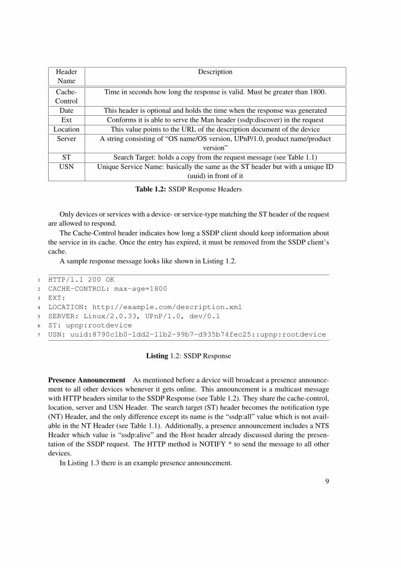
HeaderName
Description
Cache-Control
Time in seconds how long the response is valid. Must be greater than 1800.
Date This header is optional and holds the time when the response was generatedExt Conforms it is able to serve the Man header (ssdp:discover) in the request
Location This value points to the URL of the description document of the deviceServer A string consisting of “OS name/OS version, UPnP/1.0, product name/product
version”ST Search Target: holds a copy from the request message (see Table 1.1)
USN Unique Service Name: basically the same as the ST header but with a unique ID(uuid) in front of it
Table 1.2: SSDP Response Headers
Only devices or services with a device- or service-type matching the ST header of the requestare allowed to respond.
The Cache-Control header indicates how long a SSDP client should keep information aboutthe service in its cache. Once the entry has expired, it must be removed from the SSDP client’scache.
A sample response message looks like shown in Listing 1.2.
Presence Announcement As mentioned before a device will broadcast a presence announce-ment to all other devices whenever it gets online. This announcement is a multicast messagewith HTTP headers similar to the SSDP Response (see Table 1.2). They share the cache-control,location, server and USN Header. The search target (ST) header becomes the notification type(NT) Header, and the only difference except its name is the “ssdp:all” value which is not avail-able in the NT Header (see Table 1.1). Additionally, a presence announcement includes a NTSHeader which value is “ssdp:alive” and the Host header already discussed during the presen-tation of the SSDP request. The HTTP method is NOTIFY * to send the message to all otherdevices.
In Listing 1.3 there is an example presence announcement.
One important thing to mention is that a device sends multiple presence announcements toadvertise all its devices, whether embedded or not, and all of its services and nested services.There are 3 announcements for the root device, two advertisements for each embedded deviceand one advertisement for each service.
Prior a device leaves the network, it has to notify control points that it will go away bysending a bye-bye message to each advertisement it has previously sent. A bye-bye messagelooks like a presence advertisement but lacks the cache-control, location and server header. TheNTS header has the value “ssdp:bye-bye”.
Description
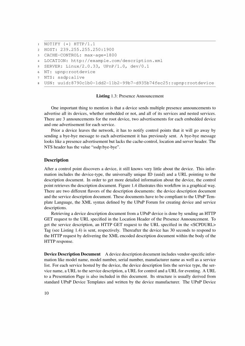
After a control point discovers a device, it still knows very little about the device. This infor-mation includes the device-type, the universally unique ID (uuid) and a URL pointing to thedescription document. In order to get more detailed information about the device, the controlpoint retrieves the description document. Figure 1.4 illustrates this workflow in a graphical way.There are two different flavors of the description documents: the device description documentand the service description document. These documents have to be compliant to the UPnP Tem-plate Language, the XML syntax defined by the UPnP Forum for creating device and servicedescriptions.
Retrieving a device description document from a UPnP device is done by sending an HTTPGET request to the URL specified in the Location Header of the Presence Announcement. Toget the service description, an HTTP GET request to the URL specified in the <SCPDURL>Tag (see Listing 1.4) is sent, respectively. Thereafter the device has 30 seconds to respond tothe HTTP request by delivering the XML encoded description document within the body of theHTTP response.
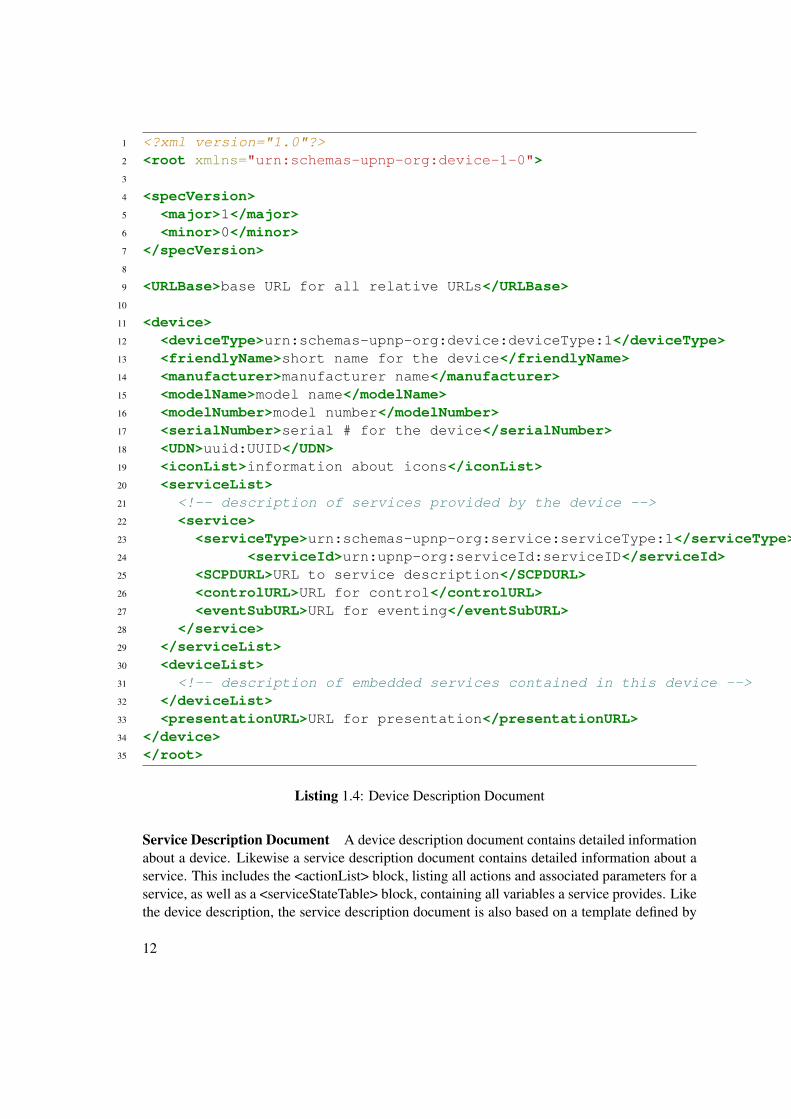
Device Description Document A device description document includes vendor-specific infor-mation like model name, model number, serial number, manufacturer name as well as a servicelist. For each service hosted by the device, the device description lists the service type, the ser-vice name, a URL to the service description, a URL for control and a URL for eventing. A URLto a Presentation Page is also included in this document. Its structure is usually derived fromstandard UPnP Device Templates and written by the device manufacturer. The UPnP Device
10
Figure 1.4: UPnP Description Phase
Templates are produced by a UPnP working committee. The Device Architecture Document [2]defines how a document has to look like in detail, but to get a quick overview how it might looklike, Listing 1.4 provides a sample device description.
9 <URLBase>base URL for all relative URLs</URLBase>10
11 <device>12 <deviceType>urn:schemas-upnp-org:device:deviceType:1</deviceType>13 <friendlyName>short name for the device</friendlyName>14 <manufacturer>manufacturer name</manufacturer>15 <modelName>model name</modelName>16 <modelNumber>model number</modelNumber>17 <serialNumber>serial # for the device</serialNumber>18 <UDN>uuid:UUID</UDN>19 <iconList>information about icons</iconList>20 <serviceList>21 <!-- description of services provided by the device -->22 <service>23 <serviceType>urn:schemas-upnp-org:service:serviceType:1</serviceType>24 <serviceId>urn:upnp-org:serviceId:serviceID</serviceId>25 <SCPDURL>URL to service description</SCPDURL>26 <controlURL>URL for control</controlURL>27 <eventSubURL>URL for eventing</eventSubURL>28 </service>29 </serviceList>30 <deviceList>31 <!-- description of embedded services contained in this device -->32 </deviceList>33 <presentationURL>URL for presentation</presentationURL>34 </device>35 </root>
Listing 1.4: Device Description Document
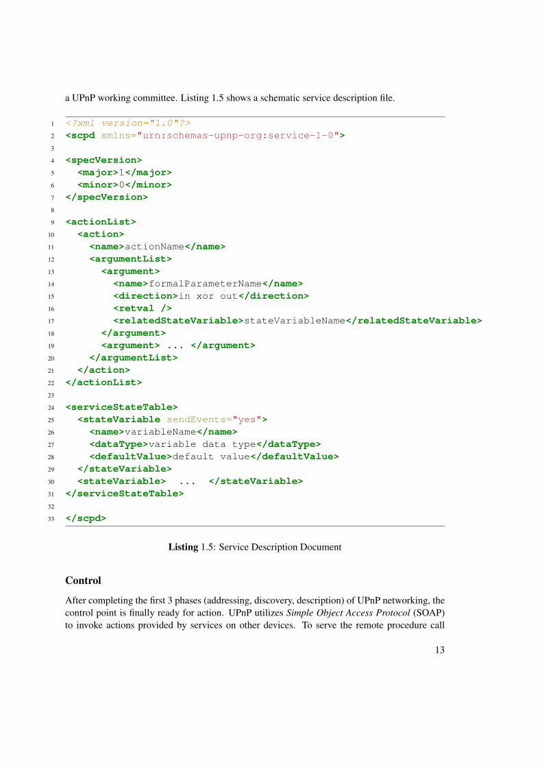
Service Description Document A device description document contains detailed informationabout a device. Likewise a service description document contains detailed information about aservice. This includes the <actionList> block, listing all actions and associated parameters for aservice, as well as a <serviceStateTable> block, containing all variables a service provides. Likethe device description, the service description document is also based on a template defined by
12
a UPnP working committee. Listing 1.5 shows a schematic service description file.
After completing the first 3 phases (addressing, discovery, description) of UPnP networking, thecontrol point is finally ready for action. UPnP utilizes Simple Object Access Protocol (SOAP)to invoke actions provided by services on other devices. To serve the remote procedure call
13
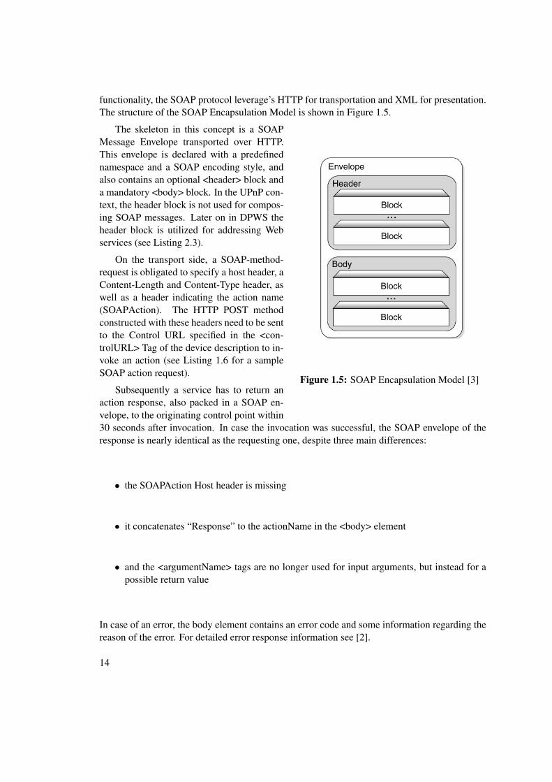
functionality, the SOAP protocol leverage’s HTTP for transportation and XML for presentation.The structure of the SOAP Encapsulation Model is shown in Figure 1.5.
Figure 1.5: SOAP Encapsulation Model [3]
The skeleton in this concept is a SOAPMessage Envelope transported over HTTP.This envelope is declared with a predefinednamespace and a SOAP encoding style, andalso contains an optional <header> block anda mandatory <body> block. In the UPnP con-text, the header block is not used for compos-ing SOAP messages. Later on in DPWS theheader block is utilized for addressing Webservices (see Listing 2.3).
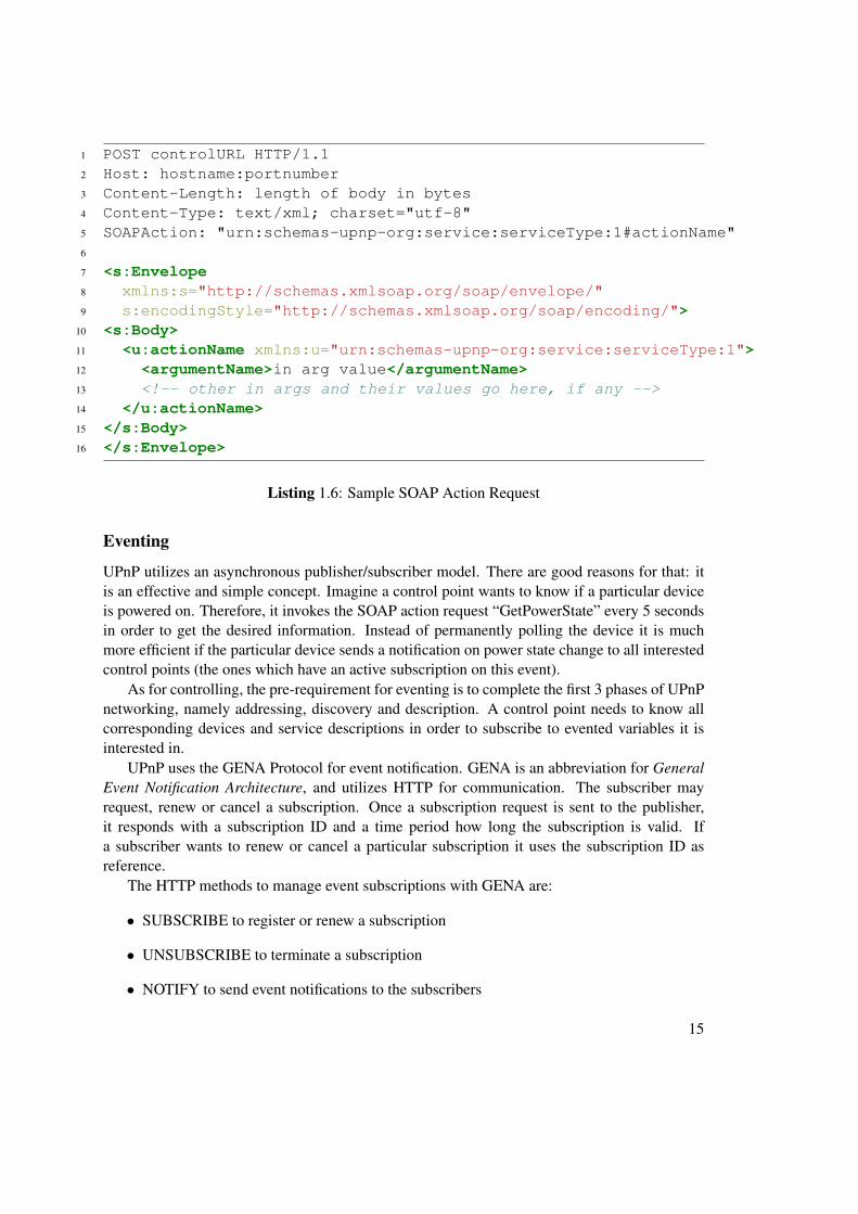
On the transport side, a SOAP-method-request is obligated to specify a host header, aContent-Length and Content-Type header, aswell as a header indicating the action name(SOAPAction). The HTTP POST methodconstructed with these headers need to be sentto the Control URL specified in the <con-trolURL> Tag of the device description to in-voke an action (see Listing 1.6 for a sampleSOAP action request).
Subsequently a service has to return anaction response, also packed in a SOAP en-velope, to the originating control point within30 seconds after invocation. In case the invocation was successful, the SOAP envelope of theresponse is nearly identical as the requesting one, despite three main differences:
• the SOAPAction Host header is missing
• it concatenates “Response” to the actionName in the <body> element
• and the <argumentName> tags are no longer used for input arguments, but instead for apossible return value
In case of an error, the body element contains an error code and some information regarding thereason of the error. For detailed error response information see [2].
14
1 POST controlURL HTTP/1.12 Host: hostname:portnumber3 Content-Length: length of body in bytes4 Content-Type: text/xml; charset="utf-8"5 SOAPAction: "urn:schemas-upnp-org:service:serviceType:1#actionName"6
10 <s:Body>11 <u:actionName xmlns:u="urn:schemas-upnp-org:service:serviceType:1">12 <argumentName>in arg value</argumentName>13 <!-- other in args and their values go here, if any -->14 </u:actionName>15 </s:Body>16 </s:Envelope>
Listing 1.6: Sample SOAP Action Request
Eventing
UPnP utilizes an asynchronous publisher/subscriber model. There are good reasons for that: itis an effective and simple concept. Imagine a control point wants to know if a particular deviceis powered on. Therefore, it invokes the SOAP action request “GetPowerState” every 5 secondsin order to get the desired information. Instead of permanently polling the device it is muchmore efficient if the particular device sends a notification on power state change to all interestedcontrol points (the ones which have an active subscription on this event).
As for controlling, the pre-requirement for eventing is to complete the first 3 phases of UPnPnetworking, namely addressing, discovery and description. A control point needs to know allcorresponding devices and service descriptions in order to subscribe to evented variables it isinterested in.
UPnP uses the GENA Protocol for event notification. GENA is an abbreviation for GeneralEvent Notification Architecture, and utilizes HTTP for communication. The subscriber mayrequest, renew or cancel a subscription. Once a subscription request is sent to the publisher,it responds with a subscription ID and a time period how long the subscription is valid. Ifa subscriber wants to renew or cancel a particular subscription it uses the subscription ID asreference.
The HTTP methods to manage event subscriptions with GENA are:
• SUBSCRIBE to register or renew a subscription
• UNSUBSCRIBE to terminate a subscription
• NOTIFY to send event notifications to the subscribers
15
It is also necessary to introduce a few new HTTP headers for GENA:
• CALLBACK the publisher uses this URL to send event notifications
• NT declares the type of notification
• NTS declares the sub-type of notification
• SID the already mentioned subscription ID
GENA’s simple publish/subscribe model maps easily to the UPnP object model: control pointsare subscribers while devices act as publishers, but there are a few aspects to consider usingGENA in a UPnP context.
One obvious thing is, a control point can only subscribe to variables declared with “send-Events=yes” in the service description. Another convention is the existence of an initial eventmessage. Whenever a control point subscribes to an event, it receives the name and value ofall evented variables provided by a service. This initial notification allows a control point tomodel the state of a service. Also each event notification contains an event key. Each time thesubscriber receives a notification, the event key will be incremented by one. This mechanism canbe used for simple error detection, because the control point can keep track of the notificationsand recognizes if it misses one.
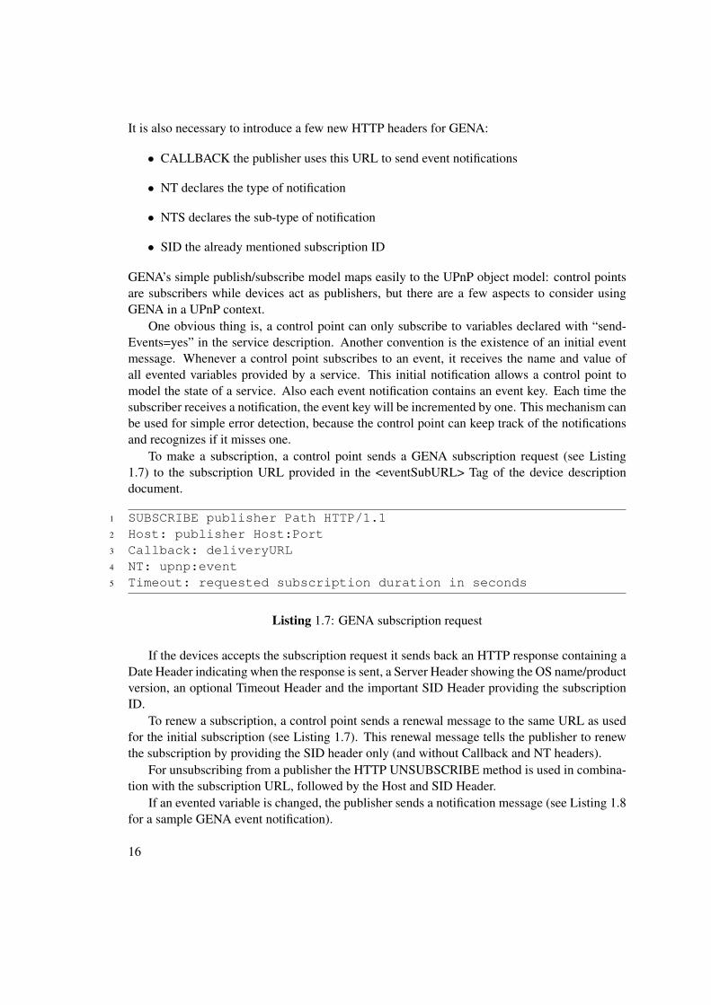
To make a subscription, a control point sends a GENA subscription request (see Listing1.7) to the subscription URL provided in the <eventSubURL> Tag of the device descriptiondocument.
If the devices accepts the subscription request it sends back an HTTP response containing aDate Header indicating when the response is sent, a Server Header showing the OS name/productversion, an optional Timeout Header and the important SID Header providing the subscriptionID.
To renew a subscription, a control point sends a renewal message to the same URL as usedfor the initial subscription (see Listing 1.7). This renewal message tells the publisher to renewthe subscription by providing the SID header only (and without Callback and NT headers).
For unsubscribing from a publisher the HTTP UNSUBSCRIBE method is used in combina-tion with the subscription URL, followed by the Host and SID Header.
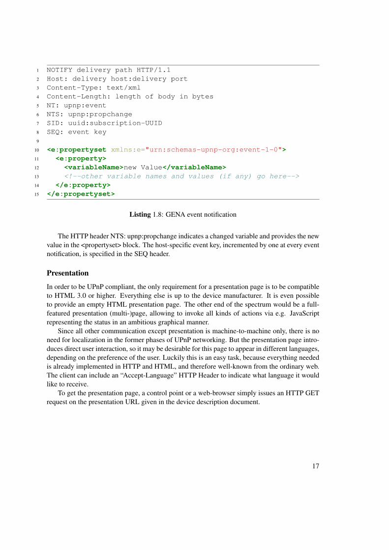
If an evented variable is changed, the publisher sends a notification message (see Listing 1.8for a sample GENA event notification).
16
1 NOTIFY delivery path HTTP/1.12 Host: delivery host:delivery port3 Content-Type: text/xml4 Content-Length: length of body in bytes5 NT: upnp:event6 NTS: upnp:propchange7 SID: uuid:subscription-UUID8 SEQ: event key9
10 <e:propertyset xmlns:e="urn:schemas-upnp-org:event-1-0">11 <e:property>12 <variableName>new Value</variableName>13 <!--other variable names and values (if any) go here-->14 </e:property>15 </e:propertyset>
Listing 1.8: GENA event notification
The HTTP header NTS: upnp:propchange indicates a changed variable and provides the newvalue in the <propertyset> block. The host-specific event key, incremented by one at every eventnotification, is specified in the SEQ header.
Presentation
In order to be UPnP compliant, the only requirement for a presentation page is to be compatibleto HTML 3.0 or higher. Everything else is up to the device manufacturer. It is even possibleto provide an empty HTML presentation page. The other end of the spectrum would be a full-featured presentation (multi-)page, allowing to invoke all kinds of actions via e.g. JavaScriptrepresenting the status in an ambitious graphical manner.
Since all other communication except presentation is machine-to-machine only, there is noneed for localization in the former phases of UPnP networking. But the presentation page intro-duces direct user interaction, so it may be desirable for this page to appear in different languages,depending on the preference of the user. Luckily this is an easy task, because everything neededis already implemented in HTTP and HTML, and therefore well-known from the ordinary web.The client can include an “Accept-Language” HTTP Header to indicate what language it wouldlike to receive.
To get the presentation page, a control point or a web-browser simply issues an HTTP GETrequest on the presentation URL given in the device description document.
17
CHAPTER 2Introduction DPWS
2.1 General Information
DPWS is an abbreviation for Device Profile for Web Services. It is basically a subset of or-dinary Web services a device must implement in order to be DPWS compliant. The DeviceProfile in the name indicates it is intended for (small) devices instead of powerful ones, result-ing in minimum requirements upon the device itself, and ensuring the possibility to run DPWSon resource-constrained embedded devices. Another key requirement for DPWS is to find aminimal set of Web service specifications, providing secure messaging, dynamic discovery, de-scription and eventing. Furthermore, this minimal set of Web services should not constrain richerimplementations.
DPWS was first introduced by Microsoft in 2004 as a successor of UPnP, designed to becompatible with the popular Web service standard. Nowadays, the DPWS Standard is definedand managed by the OASIS Consortium which represents over 600 organizations.
2.2 Components of a DPWS Network
The Device Profile for Web services aligns to the following Web service standards and protocols:
• SOAP 1.2
• WSDL 1.1 (Web Service Description Language)
• WS-Addressing 1.0
• WS-Discovery
• WS-Eventing
• WS-MetadataExchange
19
• WS-Policy
• WS-PolicyAttachment
• WS-Transfer
• WS-Security (non-normative)
Since the DPWS Profile is just a collection of Web services, the original Web service definitionsare normative unless explicitly superseded in the DPWS specification [5]. Because of that, theW3C Consortium is also responsibly for some normative references (e.g. SOAP, WSDL, WS-Addressing).
DPWS Participants
Figure 2.1 introduces the terminology of participants in a DPWS network and how these arelinked together.
Figure 2.1: DPWS Participants [5]
A device in the DPWS contextis a special type of service (a socalled Target Service) usually host-ing other services (hosted services).A hosted service is visible on thenetwork and capable of being ad-dressed separately from its host. Itslifetime is bound by the hosting Ser-vice (device). A client is a networkendpoint exchanging special typesof messages with Services. Mes-sages are responsible for discov-ery, description, control and event-ing and are always embedded in aSOAP Envelope, along with someHeaders for HTTP, TCP and IP.
2.3 Concept of DPWS
In Section 2.2 all components andparticipants of a DPWS network are introduced. Furthermore the basic interaction betweenthem is outlined. In this chapter, we take a closer look at these components and explain them indetail.
Overview of Protocols
In general, Web services are less specific regarding to the underlying transport mechanism thanUPnP. In order to be compliant to the Device Profile, SOAP over UDP must be supported (es-pecially for discovery) as well as a SOAP binding for HTTP has to be present. HTTP and UDP
20
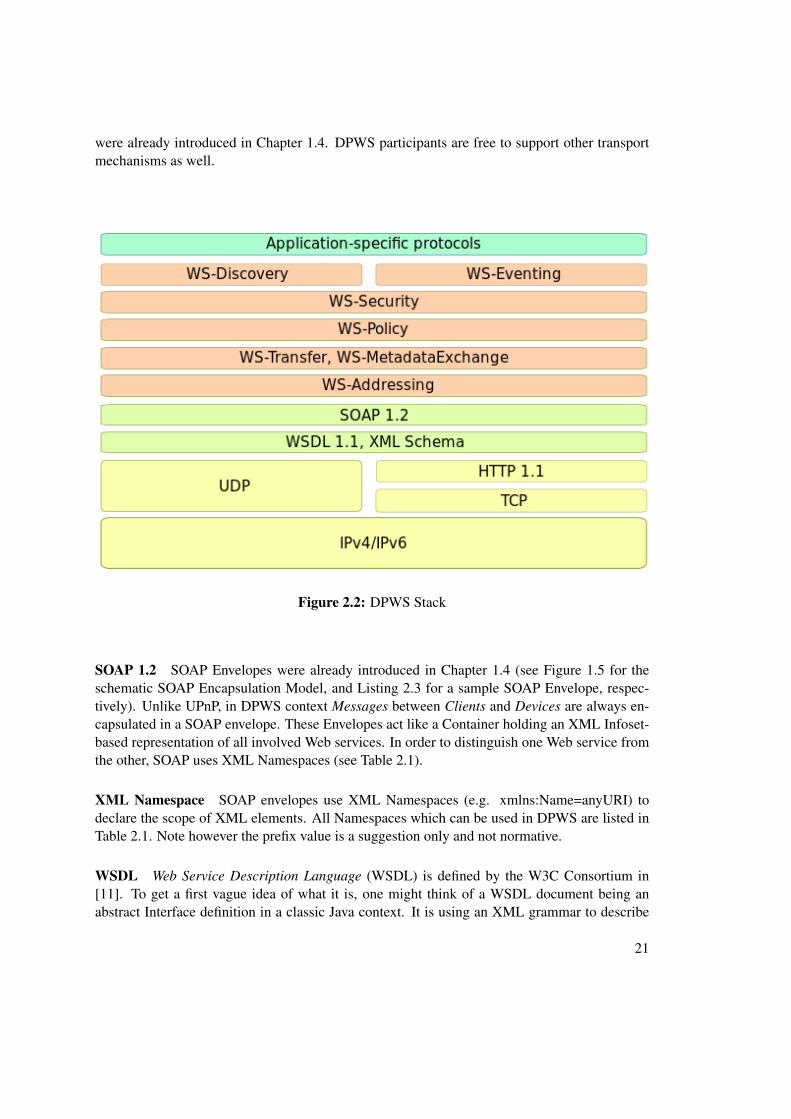
were already introduced in Chapter 1.4. DPWS participants are free to support other transportmechanisms as well.
Figure 2.2: DPWS Stack
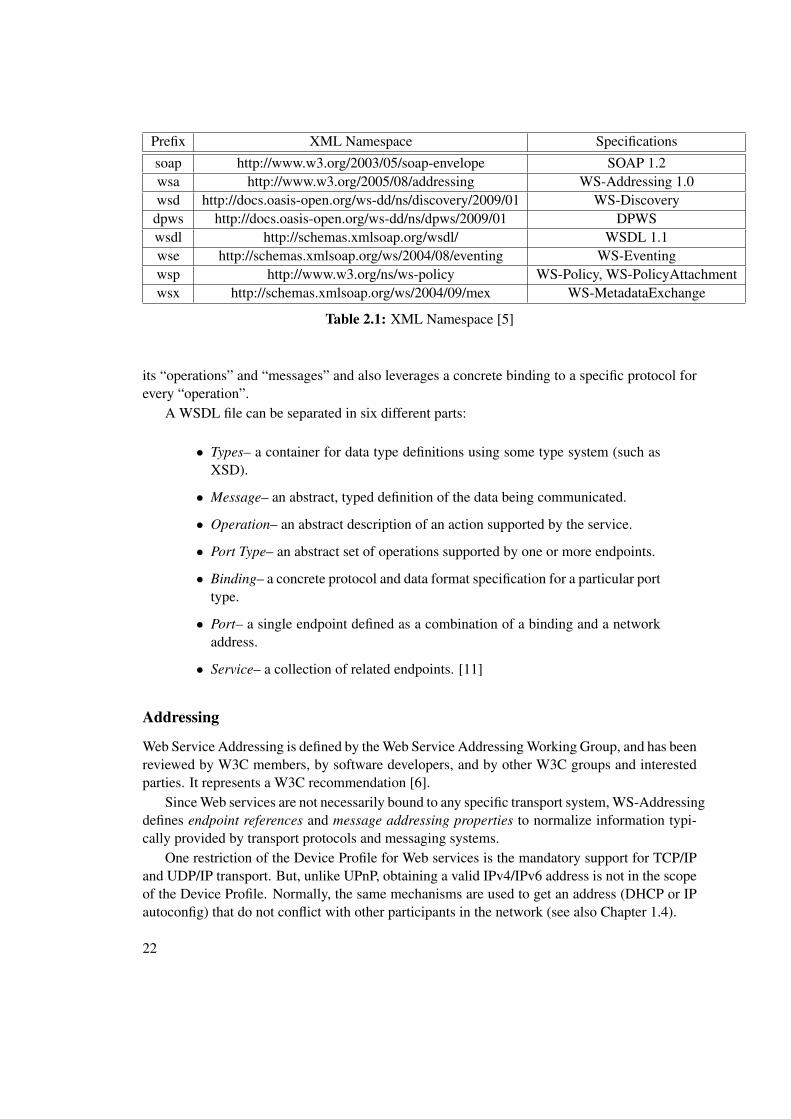
SOAP 1.2 SOAP Envelopes were already introduced in Chapter 1.4 (see Figure 1.5 for theschematic SOAP Encapsulation Model, and Listing 2.3 for a sample SOAP Envelope, respec-tively). Unlike UPnP, in DPWS context Messages between Clients and Devices are always en-capsulated in a SOAP envelope. These Envelopes act like a Container holding an XML Infoset-based representation of all involved Web services. In order to distinguish one Web service fromthe other, SOAP uses XML Namespaces (see Table 2.1).
XML Namespace SOAP envelopes use XML Namespaces (e.g. xmlns:Name=anyURI) todeclare the scope of XML elements. All Namespaces which can be used in DPWS are listed inTable 2.1. Note however the prefix value is a suggestion only and not normative.
WSDL Web Service Description Language (WSDL) is defined by the W3C Consortium in[11]. To get a first vague idea of what it is, one might think of a WSDL document being anabstract Interface definition in a classic Java context. It is using an XML grammar to describe
its “operations” and “messages” and also leverages a concrete binding to a specific protocol forevery “operation”.
A WSDL file can be separated in six different parts:
• Types– a container for data type definitions using some type system (such asXSD).
• Message– an abstract, typed definition of the data being communicated.
• Operation– an abstract description of an action supported by the service.
• Port Type– an abstract set of operations supported by one or more endpoints.
• Binding– a concrete protocol and data format specification for a particular porttype.
• Port– a single endpoint defined as a combination of a binding and a networkaddress.
• Service– a collection of related endpoints. [11]
Addressing
Web Service Addressing is defined by the Web Service Addressing Working Group, and has beenreviewed by W3C members, by software developers, and by other W3C groups and interestedparties. It represents a W3C recommendation [6].
Since Web services are not necessarily bound to any specific transport system, WS-Addressingdefines endpoint references and message addressing properties to normalize information typi-cally provided by transport protocols and messaging systems.
One restriction of the Device Profile for Web services is the mandatory support for TCP/IPand UDP/IP transport. But, unlike UPnP, obtaining a valid IPv4/IPv6 address is not in the scopeof the Device Profile. Normally, the same mechanisms are used to get an address (DHCP or IPautoconfig) that do not conflict with other participants in the network (see also Chapter 1.4).
22
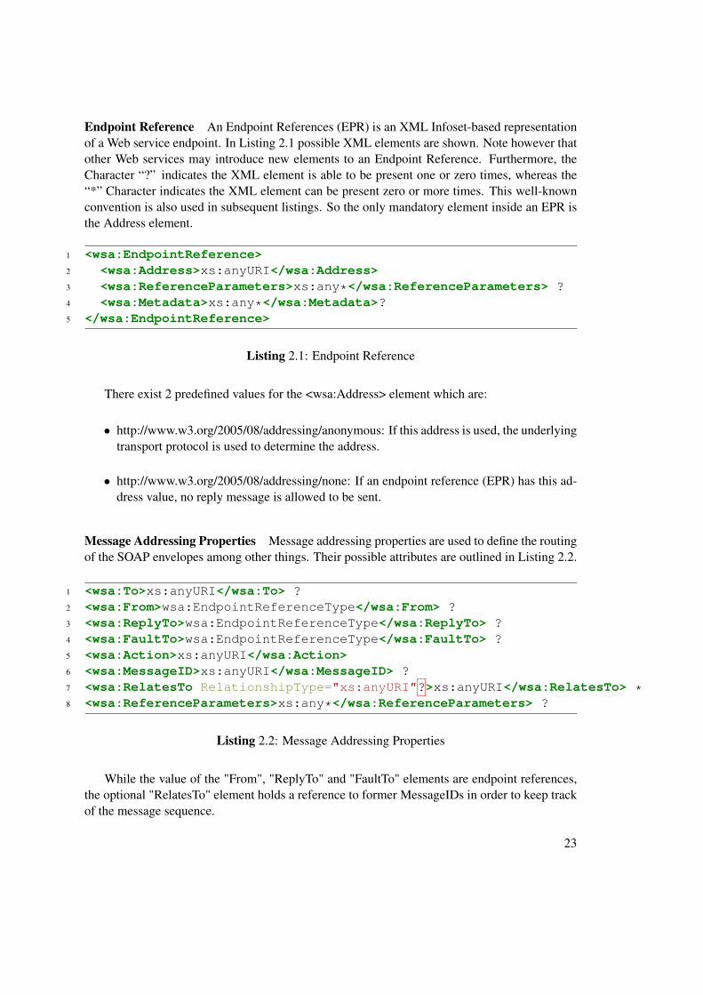
Endpoint Reference An Endpoint References (EPR) is an XML Infoset-based representationof a Web service endpoint. In Listing 2.1 possible XML elements are shown. Note however thatother Web services may introduce new elements to an Endpoint Reference. Furthermore, theCharacter “?” indicates the XML element is able to be present one or zero times, whereas the“*” Character indicates the XML element can be present zero or more times. This well-knownconvention is also used in subsequent listings. So the only mandatory element inside an EPR isthe Address element.
There exist 2 predefined values for the <wsa:Address> element which are:
• http://www.w3.org/2005/08/addressing/anonymous: If this address is used, the underlyingtransport protocol is used to determine the address.
• http://www.w3.org/2005/08/addressing/none: If an endpoint reference (EPR) has this ad-dress value, no reply message is allowed to be sent.
Message Addressing Properties Message addressing properties are used to define the routingof the SOAP envelopes among other things. Their possible attributes are outlined in Listing 2.2.
While the value of the "From", "ReplyTo" and "FaultTo" elements are endpoint references,the optional "RelatesTo" element holds a reference to former MessageIDs in order to keep trackof the message sequence.
23
WS-Addressing Example The 2 constructs of WS-Addressing, the endpoint reference andthe message addressing properties, are combined in a sample SOAP Envelope shown in Listing2.3.
Note that the addressing of a SOAP Envelope is always located in the header block. Alsothe XML Namespace usage can be seen in this example.
Discovery
WS-Discovery is defined by the OASIS Consortium [7] and is used to locate services on anetwork.
Similar to UPnP, WS-Discovery leverages a combination of active search for participants andpresence announcement if a new participant joins the network. To further reduce network trafficin the Device Profile, only devices are allowed to make themselves available for discovery (thereason a device is also called target service). So not every service sends a multicast messageto announce its presence to the network, minimizing traffic in a (possibly bandwidth-limited)network.
Multicast messages are always sent to port 3702 and use the address 239.255.255.250 forIPv4 and FF02::C for IPv6, respectively.
Hello A DPWS device will announce itself by sending a one-way multicast “Hello” messageif it joins a network or if its metadata changed. A Hello message looks like outlined it Listing2.4.
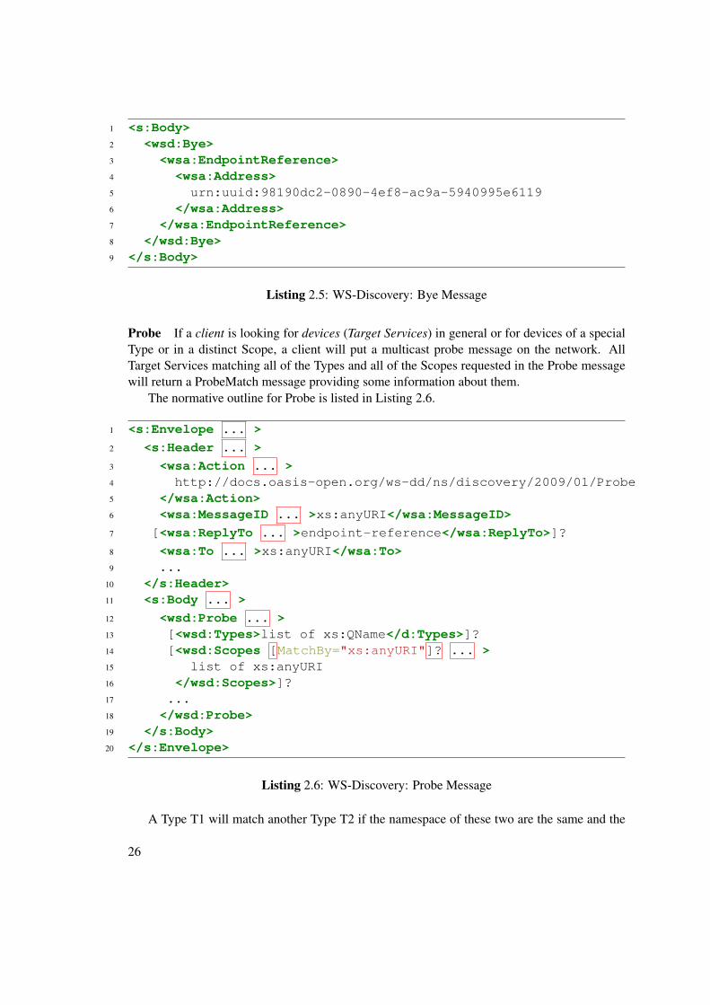
Bye When a Target Service prepares to leave the network it should send a bye message. Themessage is similar to the Hello message, but the <wsa:Action> element in the SOAP Headerchanges to “http://docs.oasis-open.org/ws-dd/ns/discovery/2009/01/Bye” and the SOAP Bodylooks like following:
Probe If a client is looking for devices (Target Services) in general or for devices of a specialType or in a distinct Scope, a client will put a multicast probe message on the network. AllTarget Services matching all of the Types and all of the Scopes requested in the Probe messagewill return a ProbeMatch message providing some information about them.
The normative outline for Probe is listed in Listing 2.6.
12 <wsd:Probe ... >13 [<wsd:Types>list of xs:QName</d:Types>]?14 [<wsd:Scopes [MatchBy="xs:anyURI"]? ... >15 list of xs:anyURI16 </wsd:Scopes>]?17 ...18 </wsd:Probe>19 </s:Body>20 </s:Envelope>
Listing 2.6: WS-Discovery: Probe Message
A Type T1 will match another Type T2 if the namespace of these two are the same and the
26
local name of T1 equals T2.To match a Scope S1 with another Scope S2, the rule used for matching has to be declared
by the MatchBy attribute inside the probe message. WS-Discovery knows the following fiverules:
• http://docs.oasis-open.org/ws-dd/ns/discovery/2009/01/none - according to this rule, a Tar-get Service only matches to a Probe if the Target Service does not have any Scope
• http://docs.oasis-open.org/ws-dd/ns/discovery/2009/01/strcmp0 - a case-sensitive string-compare is used for matching
• http://docs.oasis-open.org/ws-dd/ns/discovery/2009/01/ldap - used in a Lightweight Di-rectory Access Protocol (LDAP) Environment
• http://docs.oasis-open.org/ws-dd/ns/discovery/2009/01/uuid - compare the Universally UniqueIdentifier
• http://docs.oasis-open.org/ws-dd/ns/discovery/2009/01/rfc3986 - compare URIs e.g. "http://example.com/abc"matches "http://example.com/abc/def" in a case-insensitive manner because of the samescheme (http) and the same authority (example.com) [8]
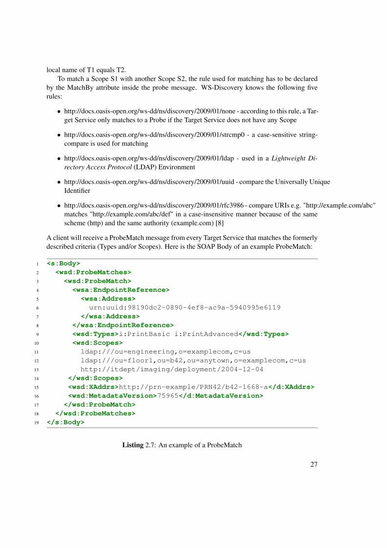
A client will receive a ProbeMatch message from every Target Service that matches the formerlydescribed criteria (Types and/or Scopes). Here is the SOAP Body of an example ProbeMatch:
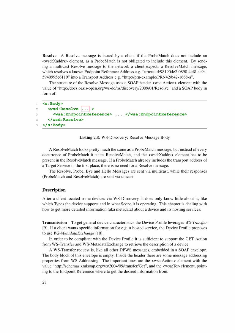
Resolve A Resolve message is issued by a client if the ProbeMatch does not include an<wsd:Xaddrs> element, as a ProbeMatch is not obligated to include this element. By send-ing a multicast Resolve message to the network a client expects a ResolveMatch message,which resolves a known Endpoint Reference Address e.g. “urn:uuid:98190dc2-0890-4ef8-ac9a-5940995e6119” into a Transport Address e.g. “http://prn-example/PRN42/b42-1668-a”.
The structure of the Resolve Message uses a SOAP header <wsa:Action> element with thevalue of “http://docs.oasis-open.org/ws-dd/ns/discovery/2009/01/Resolve” and a SOAP body inform of:
A ResolveMatch looks pretty much the same as a ProbeMatch message, but instead of everyoccurrence of ProbeMatch it states ResolveMatch, and the <wsd:Xaddrs> element has to bepresent in the ResolveMatch message. If a ProbeMatch already includes the transport address ofa Target Service in the first place, there is no need for a Resolve message.
The Resolve, Probe, Bye and Hello Messages are sent via multicast, while their responses(ProbeMatch and ResolveMatch) are sent via unicast.
Description
After a client located some devices via WS-Discovery, it does only know little about it, likewhich Types the device supports and in what Scope it is operating. This chapter is dealing withhow to get more detailed information (aka metadata) about a device and its hosting services.
Transmission To get general device characteristics the Device Profile leverages WS-Transfer[9]. If a client wants specific information for e.g. a hosted service, the Device Profile proposesto use WS-MetadataExchange [10].
In order to be compliant with the Device Profile it is sufficient to support the GET Actionfrom WS-Transfer and WS-MetadataExchange to retrieve the description of a device.
A WS-Transfer request is, like all other DPWS messages, embedded in a SOAP envelope.The body block of this envelope is empty. Inside the header there are some message addressingproperties from WS-Addressing. The important ones are the <wsa:Action> element with thevalue “http://schemas.xmlsoap.org/ws/2004/09/transfer/Get”, and the <wsa:To> element, point-ing to the Endpoint Reference where to get the desired information from.
28
The response to this WS-Transfer request is also a SOAP envelope using WS-Addressing inthe SOAP header, a <wsa:Action> element with the value “http://schemas.xmlsoap.org/ws/2004/09/transfer/GetResponse”and a SOAP body containing the payload of the requested information.
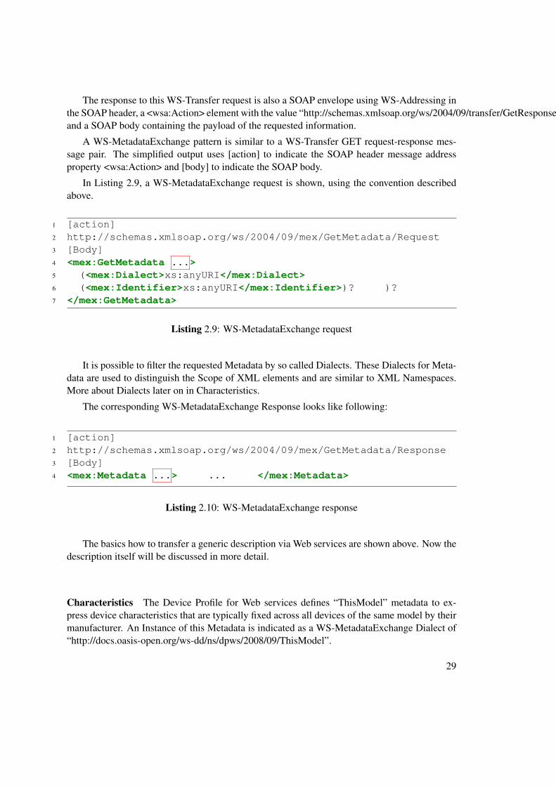
A WS-MetadataExchange pattern is similar to a WS-Transfer GET request-response mes-sage pair. The simplified output uses [action] to indicate the SOAP header message addressproperty <wsa:Action> and [body] to indicate the SOAP body.
In Listing 2.9, a WS-MetadataExchange request is shown, using the convention describedabove.
It is possible to filter the requested Metadata by so called Dialects. These Dialects for Meta-data are used to distinguish the Scope of XML elements and are similar to XML Namespaces.More about Dialects later on in Characteristics.
The corresponding WS-MetadataExchange Response looks like following:
The basics how to transfer a generic description via Web services are shown above. Now thedescription itself will be discussed in more detail.
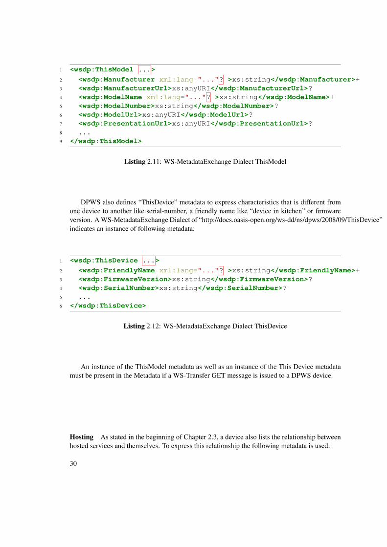
Characteristics The Device Profile for Web services defines “ThisModel” metadata to ex-press device characteristics that are typically fixed across all devices of the same model by theirmanufacturer. An Instance of this Metadata is indicated as a WS-MetadataExchange Dialect of“http://docs.oasis-open.org/ws-dd/ns/dpws/2008/09/ThisModel”.
DPWS also defines “ThisDevice” metadata to express characteristics that is different fromone device to another like serial-number, a friendly name like “device in kitchen” or firmwareversion. A WS-MetadataExchange Dialect of “http://docs.oasis-open.org/ws-dd/ns/dpws/2008/09/ThisDevice”indicates an instance of following metadata:
An instance of the ThisModel metadata as well as an instance of the This Device metadatamust be present in the Metadata if a WS-Transfer GET message is issued to a DPWS device.
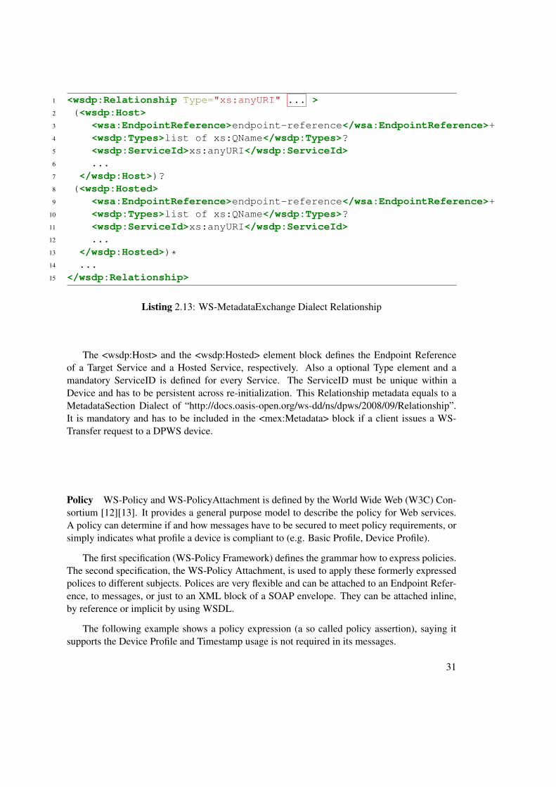
Hosting As stated in the beginning of Chapter 2.3, a device also lists the relationship betweenhosted services and themselves. To express this relationship the following metadata is used:
The <wsdp:Host> and the <wsdp:Hosted> element block defines the Endpoint Referenceof a Target Service and a Hosted Service, respectively. Also a optional Type element and amandatory ServiceID is defined for every Service. The ServiceID must be unique within aDevice and has to be persistent across re-initialization. This Relationship metadata equals to aMetadataSection Dialect of “http://docs.oasis-open.org/ws-dd/ns/dpws/2008/09/Relationship”.It is mandatory and has to be included in the <mex:Metadata> block if a client issues a WS-Transfer request to a DPWS device.
Policy WS-Policy and WS-PolicyAttachment is defined by the World Wide Web (W3C) Con-sortium [12][13]. It provides a general purpose model to describe the policy for Web services.A policy can determine if and how messages have to be secured to meet policy requirements, orsimply indicates what profile a device is compliant to (e.g. Basic Profile, Device Profile).
The first specification (WS-Policy Framework) defines the grammar how to express policies.The second specification, the WS-Policy Attachment, is used to apply these formerly expressedpolices to different subjects. Polices are very flexible and can be attached to an Endpoint Refer-ence, to messages, or just to an XML block of a SOAP envelope. They can be attached inline,by reference or implicit by using WSDL.
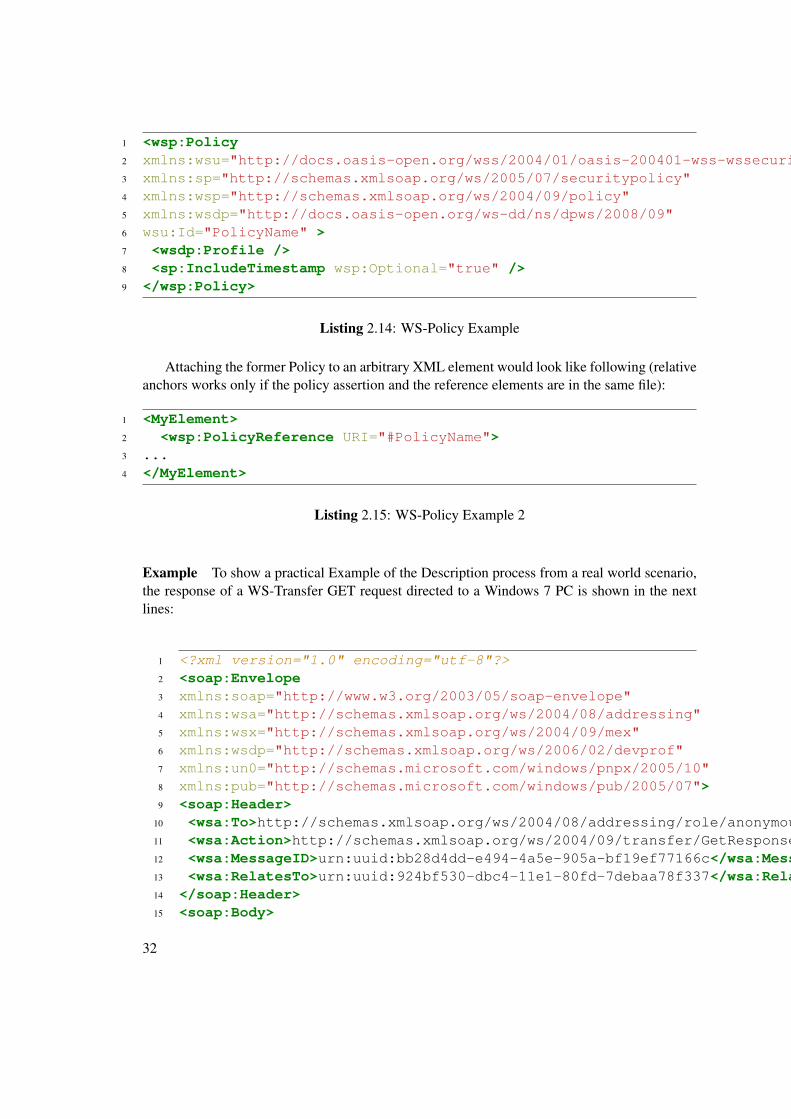
The following example shows a policy expression (a so called policy assertion), saying itsupports the Device Profile and Timestamp usage is not required in its messages.
Attaching the former Policy to an arbitrary XML element would look like following (relativeanchors works only if the policy assertion and the reference elements are in the same file):
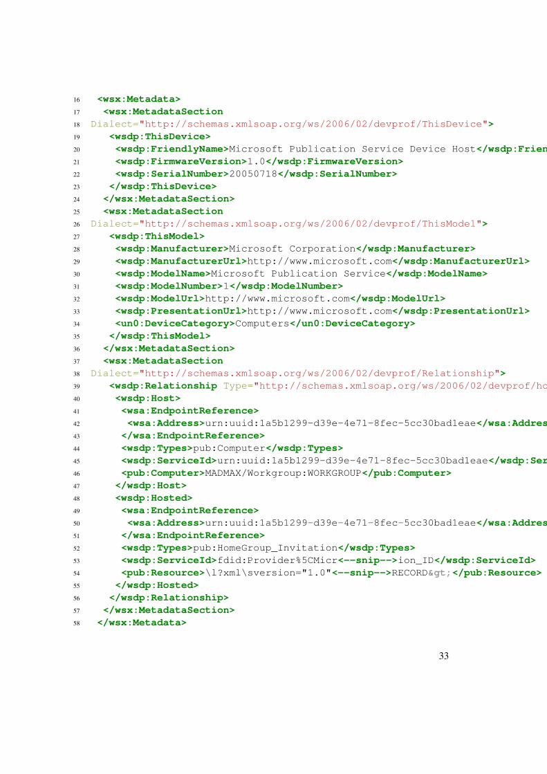
Example To show a practical Example of the Description process from a real world scenario,the response of a WS-Transfer GET request directed to a Windows 7 PC is shown in the nextlines:
Before a DPWS client is able invoke an action, it needs to know some information about it. Thisinformation can be found in the WSDL file, which was retrieved earlier in the description phase.
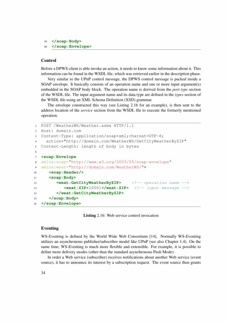
Very similar to the UPnP control message, the DPWS control message is packed inside aSOAP envelope. It basically consists of an operation name and one or more input argument(s)embedded in the SOAP body block. The operation name is derived from the port type sectionof the WSDL file. The input argument name and its data type are defined in the types section ofthe WSDL file using an XML Schema Definition (XSD) grammar.
The envelope constructed this way (see Listing 2.16 for an example), is then sent to theaddress location of the service section from the WSDL file to execute the formerly mentionedoperation.
1 POST /WeatherWS/Weather.asmx HTTP/1.12 Host: domain.com3 Content-Type: application/soap+xml;charset=UTF-8;4 action="http://domain.com/WeatherWS/GetCityWeatherByZIP"5 Content-Length: length of body in bytes6
WS-Eventing is defined by the World Wide Web Consortium [14]. Normally WS-Eventingutilizes an asynchronous publisher/subscriber model like UPnP (see also Chapter 1.4). On thesame time, WS-Eventing is much more flexible and extensible. For example, it is possible todefine more delivery modes (other than the standard asynchronous Push Mode).
In order a Web service (subscriber) receives notifications about another Web service (eventsource), it has to announce its interest by a subscription request. The event source then grants
34
the subscription or denies it. To improve robustness, a subscription is normally only valid for acertain amount of time and has to be renewed if there is still interest on notifications from theevent source.
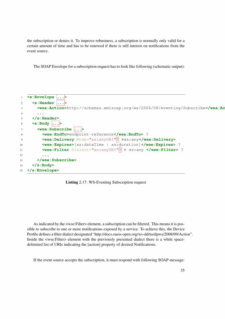
The SOAP Envelope for a subscription request has to look like following (schematic output):
As indicated by the <wse:Filter> element, a subscription can be filtered. This means it is pos-sible to subscribe to one or more notifications exposed by a service. To achieve this, the DeviceProfile defines a filter dialect designated “http://docs.oasis-open.org/ws-dd/ns/dpws/2008/09/Action”.Inside the <wse:Filter> element with the previously presented dialect there is a white space-delimited list of URIs indicating the [action] property of desired Notifications.
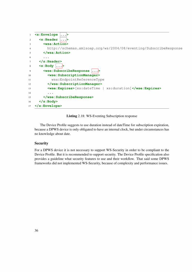
If the event source accepts the subscription, it must respond with following SOAP message:
The Device Profile suggests to use duration instead of dateTime for subscription expiration,because a DPWS device is only obligated to have an internal clock, but under circumstances hasno knowledge about date.
Security
For a DPWS device it is not necessary to support WS-Security in order to be compliant to theDevice Profile. But it is recommended to support security. The Device Profile specification alsoprovides a guideline what security features to use and their workflow. That said some DPWSframeworks did not implemented WS-Security, because of complexity and performance issues.
36
CHAPTER 3Comparison between UPnP and DPWS
3.1 General
In Chapter 1 and Chapter 2, UPnP and DPWS and their specifications were introduced. Inthis chapter these two specifications are compared to each other and their similarities will behighlighted as well as their differences.
One obvious thing is their similar logical concept. Almost for every UPnP phase (see Section1.4) there is a corresponding Web Service specification (see Section 2.3). The concept elementscommon in both specifications are Addressing, Discovery, Description, Control and Eventing.But there are also elements which do not have any direct counterparts like Presentation on theUPnP side, as well as WS-Policy and WS-Security on the DPWS side.
An important difference between UPnP and DPWS is the significant different degree of flex-ibility of these two specifications. In UPnP, almost everything is strictly standardized, from theunderlying transport mechanism to eventing there is no space for variation. Only the presenta-tion is completely up to the device manufacturer. Because of the tight specification it is ensuredthat two UPnP devices can talk to each other and are able to execute actions if available. Inthe DPWS specification, there is a lot more space for interpretation. It is possible to use differ-ent transport mechanisms for example, and especially regarding WS-Security and WS-Policy,it is not ensured that every DPWS devices can exchange messages with every other DPWS de-vice other than announce their existence and possibilities. On the other hand, with DPWS it ispossible to tailor the devices to the needs of different scenarios.
3.2 Addressing
Despite the same name, addressing has not much in common between UPnP and DPWS. In theUPnP context, addressing is all about obtaining a valid IP address in a network and uses DHCPand IP-autoconfig for this task to fulfil.
37
Since Web services are network agnostic, and DPWS is aligned to their specific Web ser-vice specifications, addressing in the DPWS context has another signification. In DPWS, everymessage is embedded in a SOAP message, and these messages can be addressed regardless oftheir underlying network. So addressing in DPWS is responsible for address routing ( e.g. spec-ify sender, receiver and who will get a response) among other things like references to formermessages and actions.
3.3 Discovery
The Discovery process in UPnP is similar to DPWS not only by name, but also by its conceptand workflow. Both uses a mix of active search of devices and a presence announcement whena new device joins the network. While UPnP is using a special protocol named SSDP (SimpleService Discovery Protocol) for Discovery, DPWS solely relies on information embedded inSOAP messages. In both specifications multicast messages are used to reach all participantsin a network with one message. The workflow can be divided into several parts and includespresence announcement, device search and a goodbye message.
Presence Announcement When a UPnP/DPWS device joins a network, it will announce itselfwith a Unique ID and a type indicating which kind of device it is. A UPnP device also gives adirection where to find detailed information of the device.
A UPnP device and a DPWS device have different approaches not only in their structure butalso in the amount of Presence announcements. While UPnP device is reporting every device(root and embedded) and every service to the network, a DPWS client is only broadcasting thetarget service.
Device Search Control-Points (UPnP) or Clients (DPWS) are able to search for devices andmay apply a filter, so only specific types of devices are replying. While these types of devicesare predefined in UPnP, in DPWS these types are declared by an XML namespace, which pointto a definition of the type. DPWS also offers to filter not only by types, but also by contextscope.
While UPnP includes the direction to a more detailed description inside its presence an-nouncement, DPWS may include a direction in its search response (a so called Probe Match). Ifthe direction (a transport address) is not included in the probe match, or only the unique ID of apresence announcement is available, the client has to issue a Resolve Request to the unique IDof the device to obtain a transport address.
Good Bye Both specifications want their devices to say good bye before leaving the network.This way, the other devices do have a clear picture of active participants on the network withoutpolling.
38
3.4 Description
The workflow how to obtain detailed description is similar in both specifications but they havetheir own way how to reach their goals.
After the Discovery phase a UPnP and a DPWS device have similar knowledge of otherdevices on the network. The information includes a unique ID (UUID) and an address where toget more information. The next step is to retrieve further information. A UPnP device retrieves aDevice Description Document located at the address specified in the LOCATION HTTP Headerof a Simple Service Discovery Protocol Response (see also Listing 1.2). A DPWS device issuesa WS-Transfer Get message to the address retrieved by a Probe or Resolve Message (see alsoListing 2.7). This way a device, whether it speaks UPnP or DPWS, gains information aboutthings like the model name, the serial number as well as the ID and the address of serviceshosted by the device.
A UPnP device can fetch more information about provided services by issuing a HTTP GETrequest to the service address (SCPDURL), and will retrieve a Service Description Documentincluding detailed information about the service capabilities and how to execute them. A DPWSdevice issues a WS-MetadataExchange request and will get a Web Service Description LanguageDocument in return. This way, the device knows all the functions a service is offering, and whatbindings they use.
It has to be noted that the DPWS approach is more flexible and the workflow is not as rigidas in UPnP. DPWS can use different ways to gain the same knowledge.
3.5 Control
Although the service definition heavily differs from DPWS and UPnP, the control messagesitself are very similar. The main difference is that UPnP uses SOAP1.1 binding and DPWS isobligated to use SOAP1.2 binding. Surprisingly, this has more affect on the HTTP headers ason the SOAP envelopes itself, which are almost identical despite their different namespaces.
While it is common sense in DPWS context to deploy your own functions including yourown function- and argument-names, this does not necessarily apply in the UPnP context. Nor-mally a UPnP forum working group defines standard services, actions, arguments and state vari-ables. If a UPnP vendor wants to extend a standard service there are some conventions to keepin mind. For example, action names and state variables have to begin with "X_" followed by avendor domain name and another underscore before the actual action or state variable name. Ifa UPnP vendor does not extend an existing service, but wants to define a completely new one, ithas to define a new serviceType within their own vendor domain name. See also Figure 4.6 foran example.
3.6 Eventing
Like in previous sections, UPnP and DPWS also use similar concepts for Eventing (asyn-chronous publish/subscribe model). But again, like in previous sections, DPWS is more flexibleand extensible than UPnP and can be extended to use other, so called Delivery Modes as well.
39
The ordinary asynchronous, event-based publish/subscriber model can be divided into sub-scribe, unsubscribe and notify.
Analogue to the discovery phase, where UPnP established a new protocol (SSDP), it alsointroduces a new protocol for the eventing task by creating new HTTP Headers. The name ofthe protocol is General Event Notification Architecture (GENA). On the other side, and alsoanalogue to its corresponding discovery phase, DPWS does not alter the HTTP Headers butencapsulates all eventing information inside a SOAP envelope.
40
CHAPTER 4Translation between UPnP and DPWS
4.1 Related Work
There are many papers covering the idea of making different home networks compatible to eachother. Basically this can be achieved in two different ways:
• translate between different networks directly,
• try to unite different home networks under one roof with the help of an intermediate pro-tocol/middleware.
A very generic approach is the Automatic Generation of Network Protocol Gateways [15].The idea is to describe the protocol in several configuration files and then use the providedcompiler to automatically generate the gateway binary.
Service-Oriented Device Communications Using the Devices Profile for Web Services [16]explains the DPWS architecture and did a performance test of an implementation of DPWSrunning on resource restricted devices. The paper also presents a gateway approach which trans-forms dumb or legacy devices into DPWS devices.
A bridge between UPnP and the fieldbus KNX (EIB) is presented and implemented by UPnPConnectivity for Home and Building Automation - A case Study for EIB [17]. The author createda bridge and a UPnP control point and succeeded in integrating KNX devices into a UPnPnetwork.
Web Services on Universal Networks [18] (WSUN) is a SOA-based framework supportingdynamic service discovery on different network environments like Jini [19], UPnP and DPWS.The services within WSUN also consider service location and service status during discovery.
The paper Using DPWS to Bridge Isolated OSGi Platforms [21] presents a solution to openup OSGi [20] platforms and make them DPWS enabled devices. This way, not only differentOSGi platforms can communicate to each other, but also native DPWS devices can utilize OSGiservices.
41
An already existing implementation for combining UPnP and DPWS networks is introducedin Home SOA – Facing Protocol Heterogeneity in Pervasive Application [22]. This very powerfulimplementation uses the OSGi platform to combine not only UPnP and DPWS but also fieldbusprotocols like X10 or ZigBee. Theoretically it can be extended via so called base drivers tosupport any other protocol as well.
4.2 Concept
The existence of a black box gateway is assumed. This gateway is able to speak UPnP andDPWS and is capable of translate between these two specifications. What functions this gatewayhas to provide exactly will be discussed in this chapter.
Translation Idea When the gateway receives a UPnP message, it has to analyse and parse themessage and hold the interesting parts in memory. These parts need to be filled into a suitableDPWS stub and then sent to the DPWS network.
If the gateway receives a DPWS message it also needs to extract certain parts and put it intoa UPnP stub. This generated message will be sent to the UPnP network. If the DPWS and UPnPdevices reside on the same network, it must be ensured the gateway does not translate its ownmessages (prevent a message-loop).
So the idea is to define what parts of a message have to be parsed or generated, to create aset of message stubs, and also to define where to put the former extracted parts into the stubs inorder to fulfil the protocol translation.
4.3 Address Mapping
There are a few requirements for the gateway regarding addressing. One is to support DHCPand Auto-IP. Also a Message ID and sometimes an AppSequence has to be generated and filledinto a suiting stub. See also next chapter or Figure 4.1 for more information and examples.
4.4 Discovery Mapping
A first step for a UPnP-DPWS gateway is to introduce all devices available in the network toall other devices, regardless if they speak UPnP or DPWS. So a UPnP Device needs to knowthe existence of a DPWS client in the network and vice versa. Therefore, it has to translatethe “presence announcement” as well as the “device searches” and “good-bye messages” fromUPnP to DPWS and from DPWS to UPnP.
Presence Announcement
UPnP to DPWS When the gateway receives a Simple Service Discovery Protocol MulticastMessage, it has to parse the USN header containing the UUID of the device, the NT headercontaining the device type, as well as the LOCATION header. On the USN header value, the
42
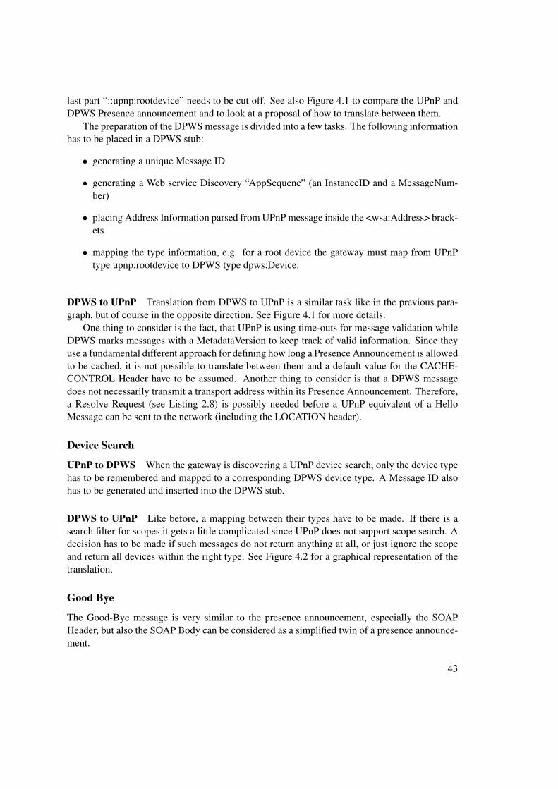
last part “::upnp:rootdevice” needs to be cut off. See also Figure 4.1 to compare the UPnP andDPWS Presence announcement and to look at a proposal of how to translate between them.
The preparation of the DPWS message is divided into a few tasks. The following informationhas to be placed in a DPWS stub:
• generating a unique Message ID
• generating a Web service Discovery “AppSequenc” (an InstanceID and a MessageNum-ber)
• placing Address Information parsed from UPnP message inside the <wsa:Address> brack-ets
• mapping the type information, e.g. for a root device the gateway must map from UPnPtype upnp:rootdevice to DPWS type dpws:Device.
DPWS to UPnP Translation from DPWS to UPnP is a similar task like in the previous para-graph, but of course in the opposite direction. See Figure 4.1 for more details.
One thing to consider is the fact, that UPnP is using time-outs for message validation whileDPWS marks messages with a MetadataVersion to keep track of valid information. Since theyuse a fundamental different approach for defining how long a Presence Announcement is allowedto be cached, it is not possible to translate between them and a default value for the CACHE-CONTROL Header have to be assumed. Another thing to consider is that a DPWS messagedoes not necessarily transmit a transport address within its Presence Announcement. Therefore,a Resolve Request (see Listing 2.8) is possibly needed before a UPnP equivalent of a HelloMessage can be sent to the network (including the LOCATION header).
Device Search
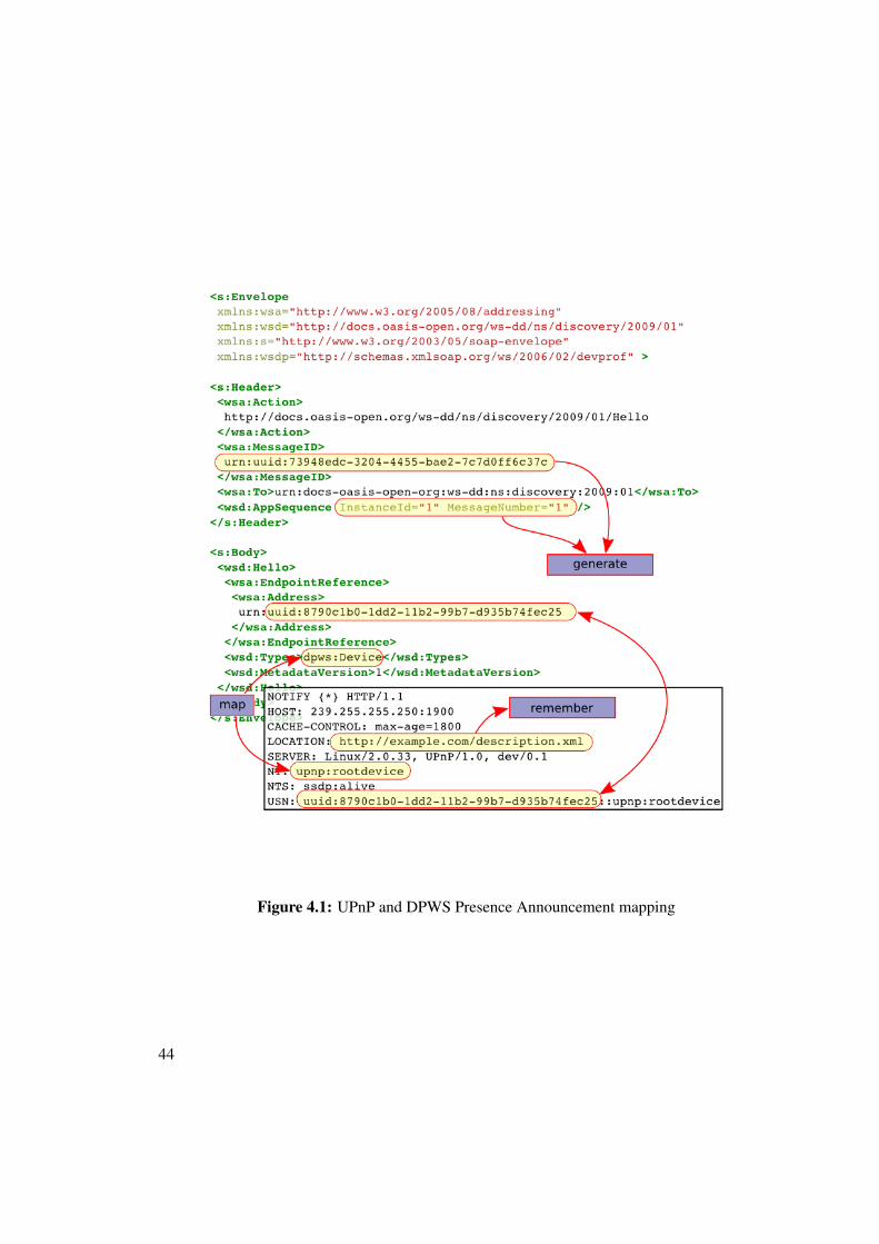
UPnP to DPWS When the gateway is discovering a UPnP device search, only the device typehas to be remembered and mapped to a corresponding DPWS device type. A Message ID alsohas to be generated and inserted into the DPWS stub.
DPWS to UPnP Like before, a mapping between their types have to be made. If there is asearch filter for scopes it gets a little complicated since UPnP does not support scope search. Adecision has to be made if such messages do not return anything at all, or just ignore the scopeand return all devices within the right type. See Figure 4.2 for a graphical representation of thetranslation.
Good Bye
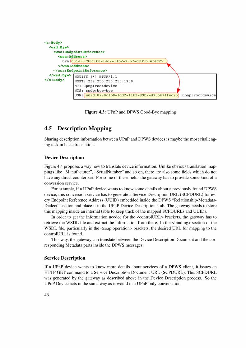
The Good-Bye message is very similar to the presence announcement, especially the SOAPHeader, but also the SOAP Body can be considered as a simplified twin of a presence announce-ment.
43
Figure 4.1: UPnP and DPWS Presence Announcement mapping
44
Figure 4.2: UPnP and DPWS Device Search mapping
UPnP to DPWS Parsing a UPnP Good-Bye message is easy since only the USN Header needto be remembered and placed in the DPWS stub. Within the Good-Bye message the namespaceand address declarations are the same as in the presence announcement despite a “Hello” be-comes a “Bye” in the <wsa:Action> brackets. Only the SOAP Body differs slightly. Thereforeand to keep things short Figure 4.3 misses the namespace and address declaration and only showthe SOAP Body of the DPWS Good-Bye stub.
DPWS to UPnP The <wsa:Address> value will be inserted in the UPnP stub at the USNHeader position and is extended by the string “::upnp:rootdevice”
45
Figure 4.3: UPnP and DPWS Good-Bye mapping
4.5 Description Mapping
Sharing description information between UPnP and DPWS devices is maybe the most challeng-ing task in basic translation.
Device Description
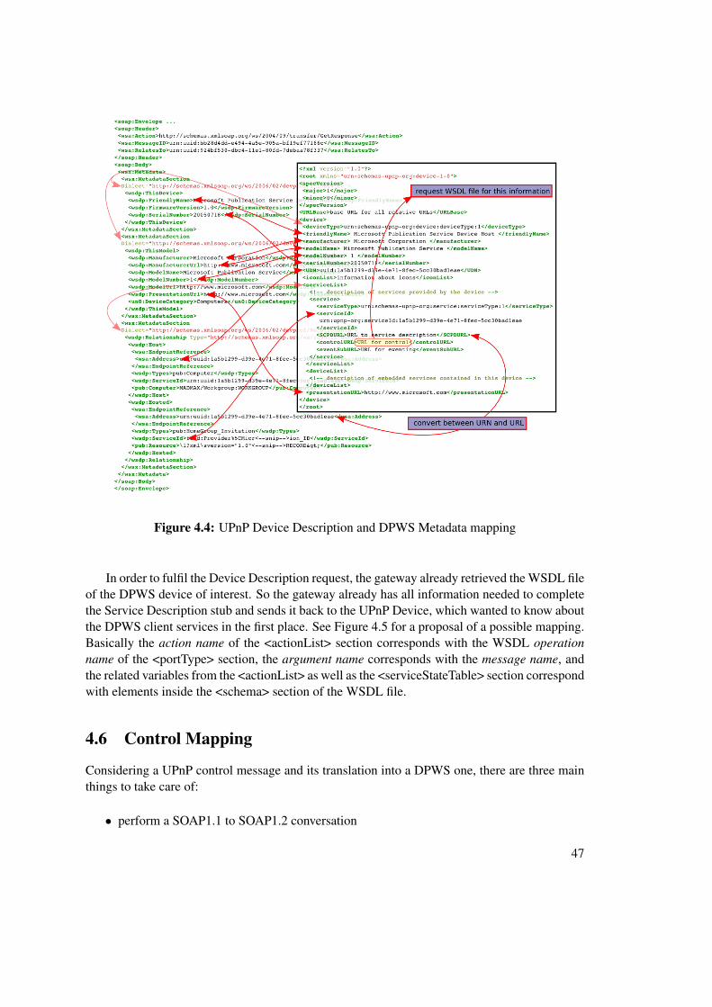
Figure 4.4 proposes a way how to translate device information. Unlike obvious translation map-pings like “Manufacturer”, “SerialNumber” and so on, there are also some fields which do nothave any direct counterpart. For some of these fields the gateway has to provide some kind of aconversion service.
For example, if a UPnP device wants to know some details about a previously found DPWSdevice, this conversion service has to generate a Service Description URL (SCPDURL) for ev-ery Endpoint Reference Address (UUID) embedded inside the DPWS “Relationship-Metadata-Dialect” section and place it in the UPnP Device Description stub. The gateway needs to storethis mapping inside an internal table to keep track of the mapped SCPDURLs and UUIDs.
In order to get the information needed for the <controlURL> brackets, the gateway has toretrieve the WSDL file and extract the information from there. In the <binding> section of theWSDL file, particularly in the <soap:operation> brackets, the desired URL for mapping to thecontrolURL is found.
This way, the gateway can translate between the Device Description Document and the cor-responding Metadata parts inside the DPWS messages.
Service Description
If a UPnP device wants to know more details about services of a DPWS client, it issues anHTTP GET command to a Service Description Document URL (SCPDURL). This SCPDURLwas generated by the gateway as described above in the Device Description process. So theUPnP Device acts in the same way as it would in a UPnP only conversation.
46
Figure 4.4: UPnP Device Description and DPWS Metadata mapping
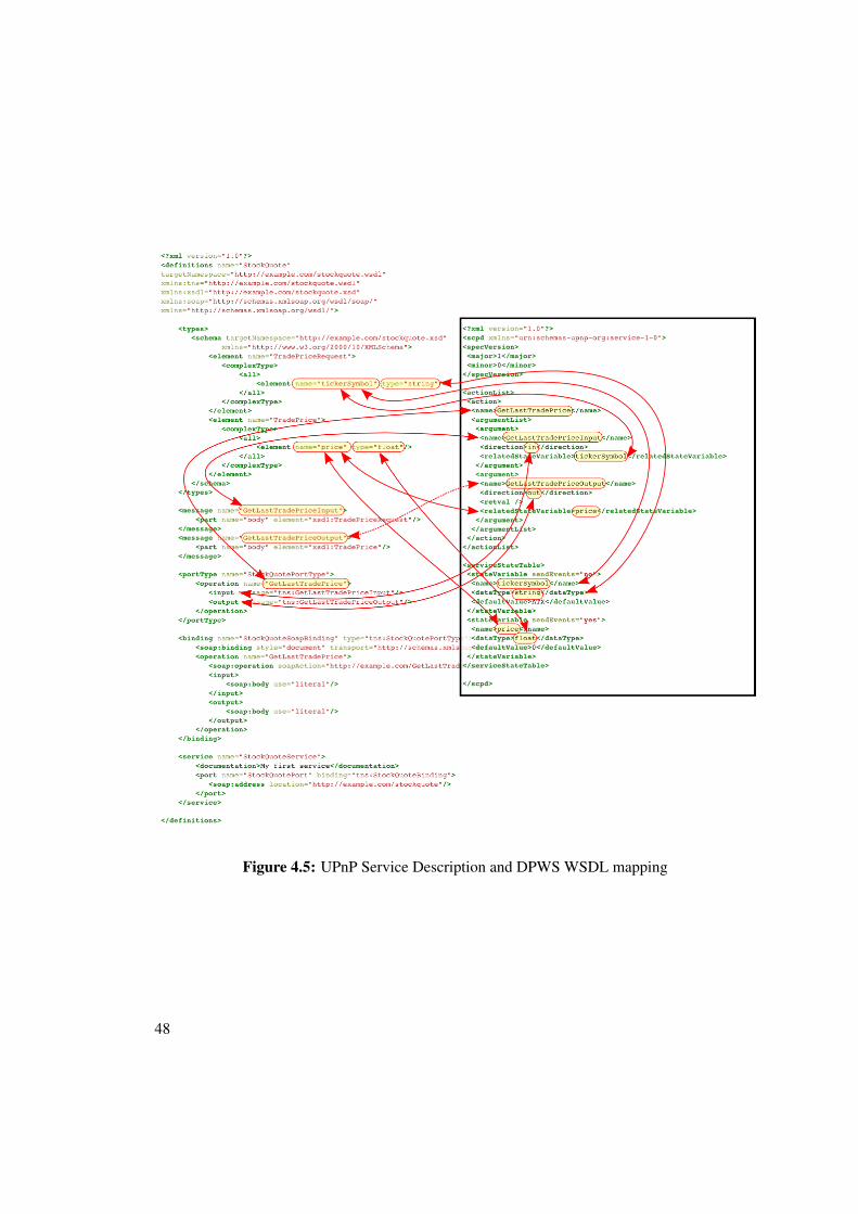
In order to fulfil the Device Description request, the gateway already retrieved the WSDL fileof the DPWS device of interest. So the gateway already has all information needed to completethe Service Description stub and sends it back to the UPnP Device, which wanted to know aboutthe DPWS client services in the first place. See Figure 4.5 for a proposal of a possible mapping.Basically the action name of the <actionList> section corresponds with the WSDL operationname of the <portType> section, the argument name corresponds with the message name, andthe related variables from the <actionList> as well as the <serviceStateTable> section correspondwith elements inside the <schema> section of the WSDL file.
4.6 Control Mapping
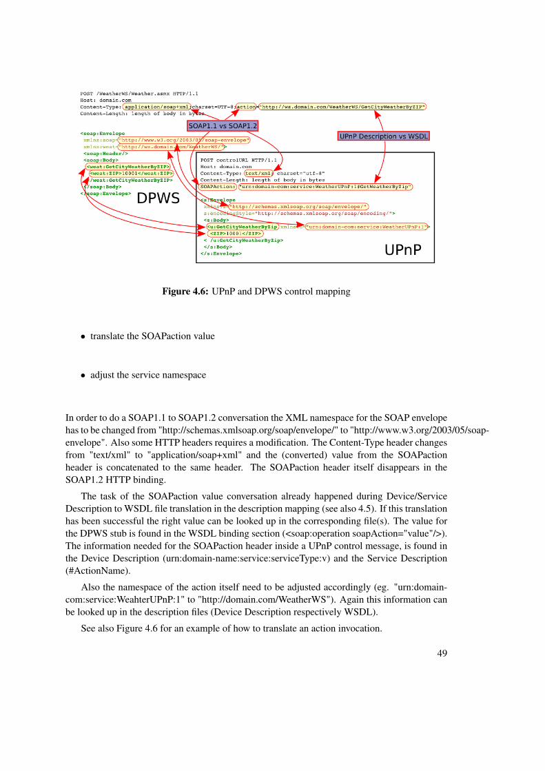
Considering a UPnP control message and its translation into a DPWS one, there are three mainthings to take care of:
• perform a SOAP1.1 to SOAP1.2 conversation
47
Figure 4.5: UPnP Service Description and DPWS WSDL mapping
48
Figure 4.6: UPnP and DPWS control mapping
• translate the SOAPaction value
• adjust the service namespace
In order to do a SOAP1.1 to SOAP1.2 conversation the XML namespace for the SOAP envelopehas to be changed from "http://schemas.xmlsoap.org/soap/envelope/" to "http://www.w3.org/2003/05/soap-envelope". Also some HTTP headers requires a modification. The Content-Type header changesfrom "text/xml" to "application/soap+xml" and the (converted) value from the SOAPactionheader is concatenated to the same header. The SOAPaction header itself disappears in theSOAP1.2 HTTP binding.
The task of the SOAPaction value conversation already happened during Device/ServiceDescription to WSDL file translation in the description mapping (see also 4.5). If this translationhas been successful the right value can be looked up in the corresponding file(s). The value forthe DPWS stub is found in the WSDL binding section (<soap:operation soapAction="value"/>).The information needed for the SOAPaction header inside a UPnP control message, is found inthe Device Description (urn:domain-name:service:serviceType:v) and the Service Description(#ActionName).
Also the namespace of the action itself need to be adjusted accordingly (eg. "urn:domain-com:service:WeahterUPnP:1" to "http://domain.com/WeatherWS"). Again this information canbe looked up in the description files (Device Description respectively WSDL).
See also Figure 4.6 for an example of how to translate an action invocation.
49
4.7 Event Mapping
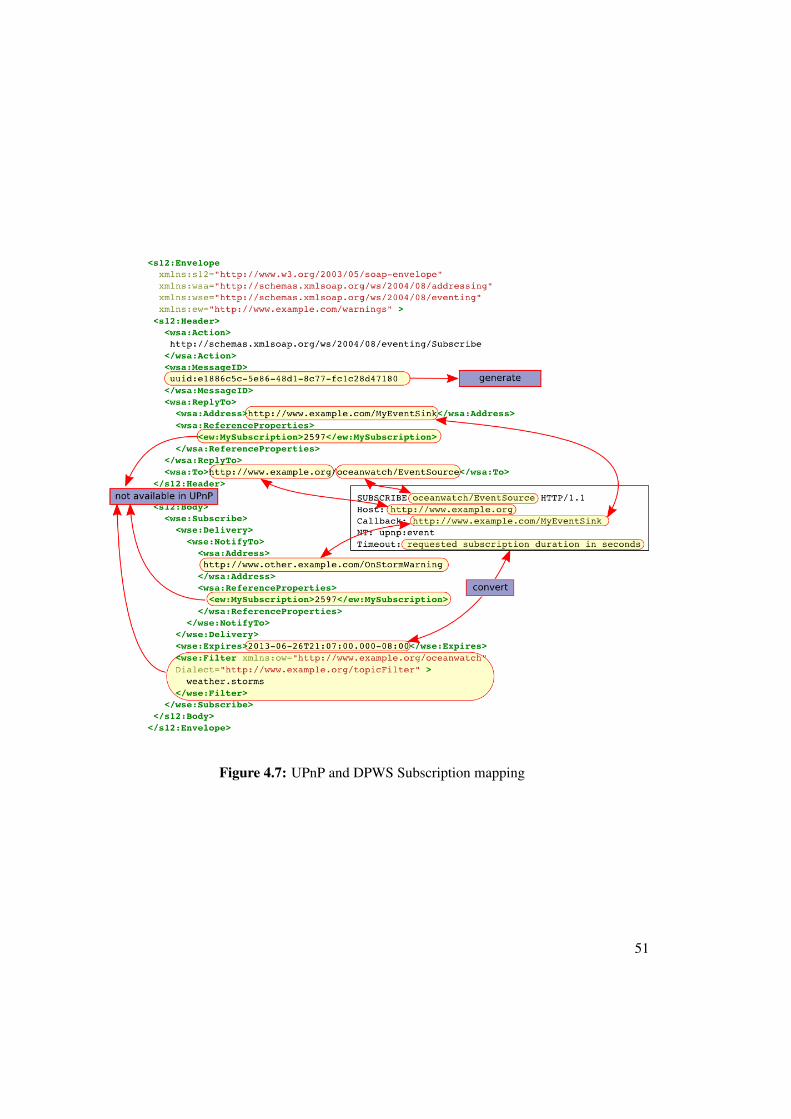
Subscribe
If a device likes to subscribe to an event source, it needs almost the same information in botharchitectures (UPnP and DPWS). The information includes an address of the event source towhich the device wants subscribe to, a callback address where the notifications should go to andthe amount of time the subscription should be valid.
But like so many times before, the flexibility of DPWS makes it difficult to achieve a realtranslation of these messages.
One problematic issue might be the possibility of DPWS to distinguish between the addresswhere the reply to the subscription should be sent, and the address where the actual notificationgoes to. In other words the possibility of having a subscription manager is absent in UPnP.
Another issue is that the DPWS Endpoint Reference is often extended by <wsa:ReferenceProperties>to carry proprietary information. Often this extension is used to keep track of the subscriptionsand therefore holds a subscription ID. UPnP also knows the concept of a subscription ID, but ina UPnP network the event source determines this ID (in UPnP context also referred to SID).
Furthermore, DPWS has the ability to set a filter for a subscription, so it only receives anotification if the filter criteria are met. In UPnP, a device issues a subscription to a service andreceives all updates of this particular service.
Another minor issue to take into account is that DPWS may express the expire time in date-time or in seconds whereas UPnP only takes care of seconds. A simple conversion is possiblyneeded if DPWS uses a datetime notation.
Figure 4.7 compares the subscription message between UPnP and DPWS and outlines whatinformation has to be exchanged.
50
Figure 4.7: UPnP and DPWS Subscription mapping
51
CHAPTER 5Conclusion
5.1 General
Due to the great flexibility of DPWS it is difficult to generate a universally valid gateway betweenUPnP and DPWS. But since structure and workflow are similar, under certain circumstances itshould be possible to hand craft a translator between these two specifications.
One key part for translation is to find a way how to map types and functions since theyare kind of static in UPnP (predefined by a working committee of the UPnP Forum) but notpredefined at all in DPWS. In DPWS, every manufacturer define own types and functions andinclude their definitions via namespace. Therefore, it is better to know them in advance and doa manual mapping e.g. via a table.
Another thing to keep in mind is even though the communication between these two specifi-cations might be possible, this does not mean all end-user devices are compatible to each other.There are still a lot of pitfalls to come over like application-specific protocols on top of the ba-sic specification (e.g. UPnP-AV). While it might be possible to extend the gateway in a waythe application-specific protocols are supported too, there are scenarios where no communica-tion between UPnP and DPWS devices is possible at all, like incompatible policy or securityrequirements.
53
CHAPTER 6Bibliographic Issues
55
Bibliography
[1] Microsoft Cooperation. Understanding Universal Plug and Play -www.upnp.org/download/UPNP_UnderstandingUPNP.doc
[2] UPnP Forum. UPnP Device Architecture 1.1, http://upnp.org/specs/arch/UPnP-arch-DeviceArchitecture-v1.1.pdf, October 2008
[3] Michael Jeronimo, UPnP Design by Example , Jack Weast. 2003 Intel Press
[5] Toby Nixon, et al, Devices Profile for Web Services Version 1.1, http://docs.oasis-open.org/ws-dd/dpws/1.1/os/wsdd-dpws-1.1-spec-os.pdf, July 2009
[6] Martin Gudgin, et al, Web Services Addressing 1.0 Core,http://www.w3.org/TR/2006/REC-ws-addr-core-20060509/ , 9 May 2006
[7] Toby Nixon, et al, Web Services Dynamic Discovery (WS-Discovery)Version 1.1, http://docs.oasis-open.org/ws-dd/discovery/1.1/wsdd-discovery-1.1-spec.html, July 2009
[8] T. Berners-Lee, et al, Uniform Resource Identifiers (URI): Generic Syntax , IETFRFC 3986, http://www.ietf.org/rfc/rfc3986.txt, January 2005
[9] Jan Alexander, at el, Web Services Transfer (WS-Transfer),http://www.w3.org/Submission/2006/SUBM-WS-Transfer-20060315/, March2006
[10] Keith Ballinger, at el, Web Services Metadata Exchange 1.1 (WS-MetadataExchange), http://www.w3.org/Submission/2008/SUBM-WS-MetadataExchange-20080813, August 2008
[11] Erik Christensen, Web Services Description Language (WSDL) 1.1,http://www.w3.org/TR/2001/NOTE-wsdl-20010315, March 2001
[12] Siddharth Bajaj, et al, Web Services Policy 1.2 - Framework (WS-Policy),http://www.w3.org/Submission/2006/SUBM-WS-Policy-20060425, April 2006
57
[13] Siddharh Bajaj, et al, Web Services Policy 1.2 - Attachment (WS-PolicyAttachment), http://www.w3.org/Submission/2006/SUBM-WS-PolicyAttachment-20060425/, April 2006
[14] Don Box, et al, Web Services Eventing (WS-Eventing),http://www.w3.org/Submission/WS-Eventing/, March 2006
[15] Automatic Generation of Network Protocol Gateways - Yerom-David Bromberg ,Laurent Reveillere , Julia L. Lawall , Gilles Muller. 2009 Springer Verlag
[16] Service-Oriented Device Communications Using the Devices Profile for Web Ser-vices - François Jammes, Antoine Mensch, Harm Smit. 2005 ACM 1-59593-268-2/05/11
[17] UPnP Connectivity for Home and Building Automation A case Study for EIB;Horst Scheichelbauer. 2003, TU Vienna, Master Thesis
[18] Web Services on Universal Networks - Yun-Young Hwang, Il-Jin Oh, Hyung-JunYim, Kyong-Ha Lee, Kangchan Lee, Seungyun Lee, Kyu-Chul Lee. ChungnamNational University&Electronic and Telecommunications Research Institute, Ko-rea
[19] Jini Community, http://www.jini.org.
[20] OSGi Alliance, OSGi Service Platform Core Specification and Service Com-pendium - Release 4, Version 4.2, 2009
[21] Towards the Web of Things: Using DPWS to Bridge Isolated OSGi Platforms -Oliver Dohndorf, Jan Krüger, Heiko Krumm; Christoph Fiehe, Anna Litvina, IngoLück, Franz-Josef Stewing. 2008 IEEE 978-0-7695-3367-4/08
[22] Home SOA – Facing Protocol Heterogeneity in Pervasive Application - AndréBottaro, Anne Gérodolle. 2008 ACM 978-1-60558-135-4/08/07


![UPnP & Konnex · Das UPnP Forum [UPnP-Forum]ist ein Zusammenschluss führender Hersteller aus der Unterhaltungs- und Computerindustrie. Es wurde im Juni 1999 gegründet und zählt](https://static.unterlagen.site/doc/80x56/5e1bff200e2a4a15a230d247/upnp-das-upnp-forum-upnp-forumist-ein-zusammenschluss-fhrender-hersteller.jpg)


