THERMASGARD ® MODBUS D G F r Herzlichen Glückwunsch! Sie haben ein deutsches Qualitätsprodukt erworben. Congratulations! You have bought a German quality product. Félicitations ! Vous avez fait l’acquisition d’un produit allemand de qualité. Примите наши поздравления ! Вы приобрели качественный продукт, изготовленный в Германии. D Bedienungs- und Montageanleitung Temperaturmessumformer, kalibrierfähig, mit Modbus-Anschluss G Operating Instructions, Mounting & Installation Temperature measuring transducers, calibratable, with Modbus connection F Notice d’instruction Sondes avec convertisseur de mesure, étalonnable, avec raccordement Modbus r Руководство по монтажу и обслуживанию Преобразователь температуры измерительный, калибруемый, с возможностью подключения к шине Modbus S+S REGELTECHNIK GMBH PIRNAER STRASSE 20 90411 NÜRNBERG ⁄ GERMANY FON +49 (0) 911 ⁄ 5 19 47-0 FAX +49 (0) 911 ⁄ 5 19 47-70 [email protected]www.SplusS.de 6000-3120-0000-1XX 31200-2018 V102 01 ⁄ 2018
Transcript
THERMASGARD® MODBUS
D G F r
Herzlichen Glückwunsch! Sie haben ein deutsches Qualitätsprodukt erworben.
Congratulations! You have bought a German quality product.
Félicitations ! Vous avez fait l’acquisition d’un produit allemand de qualité.
Примите наши поздравления ! Вы приобрели качественный продукт, изготовленный в Германии.
D Bedienungs- und Montageanleitung
Temperaturmessumformer, kalibrierfähig, mit Modbus-Anschluss
G Operating Instructions, Mounting & Installation
Temperature measuring transducers, calibratable, with Modbus connection
F Notice d’instruction
Sondes avec convertisseur de mesure, étalonnable, avec raccordement Modbus
r Руководство по монтажу и обслуживанию
Преобразователь температуры измерительный, калибруемый, с возможностью подключения к шине Modbus
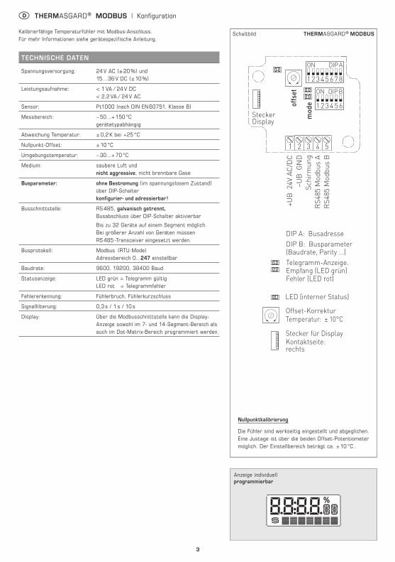
Statusanzeige: LED grün = Telegramm gültig LED rot = Telegrammfehler
Fehlererkennung: Fühlerbruch, Fühlerkurzschluss
Signalfilterung: 0,3 s / 1 s / 10 s
Display: Über die Modbusschnittstelle kann die Display-Anzeige sowohl im 7- und 14-Segment-Bereich als auch im Dot-Matrix-Bereich programmiert werden.
Anzeige individuell programmierbar
Nullpunktkalibrierung
Die Fühler sind werkseitig eingestellt und abgeglichen. Eine Justage ist über die beiden Offset-Potentio meter möglich. Der Einstellbereich beträgt ca. ± 10 °C .
4
D THERMASGARD® MODBUS | Konfiguration
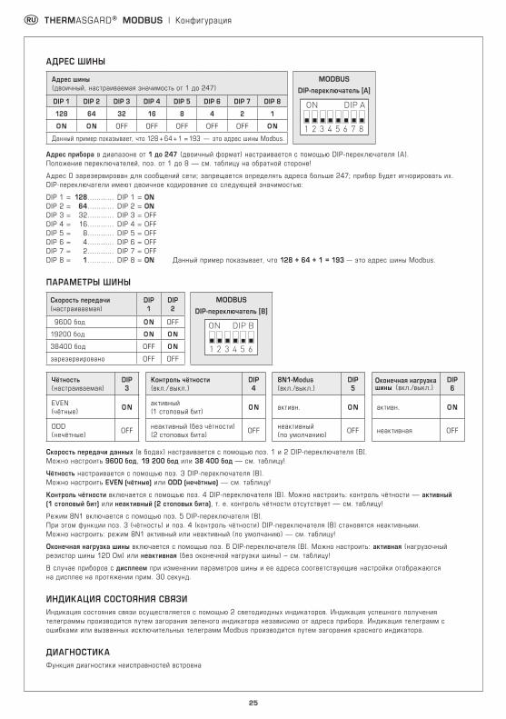
BUSADRESSE
Busadresse (binärcodiert, Wertigkeit 1 bis 247 einstellbar)
MODBUSDIP-Schalter [A]
DIP 1 DIP 2 DIP 3 DIP 4 DIP 5 DIP 6 DIP 7 DIP 8
1 2 3 4 5 6 7 8
ON DIP A128 64 32 16 8 4 2 1
O N O N OFF OFF OFF OFF OFF O N
Beispiel zeigt 128 + 64 + 1 = 193 als Modbus-Adresse.
Die Geräteadresse im Bereich von 1 bis 247 (Binärformat) wird über den DIP-Schalter [A] eingestellt. Schalterstellung Pos. 1 bis 8 – siehe Tabelle auf Rückseite!
Die Adresse 0 ist für Broadcast-Meldungen reserviert, die Adressen größer 247 dürfen nicht belegt werden und werden vom Gerät ignoriert. Die DIP-Schalter sind binärcodiert mit folgender Wertigkeit:
DIP 1 = 128 ............ DIP 1 = ON DIP 2 = 64 ............ DIP 2 = ON DIP 3 = 32 ............ DIP 3 = OFF DIP 4 = 16 ............ DIP 4 = OFF DIP 5 = 8 ............ DIP 5 = OFF DIP 6 = 4 ............ DIP 6 = OFF DIP 7 = 2 ............ DIP 7 = OFF DIP 8 = 1 ............ DIP 8 = ON folgt die Modbus-Adresse 128 + 64 + 1 = 193
BUSPARAMETER
Baudrate (einstellbar)
DIP 1
DIP 2
MODBUSDIP-Schalter [B]
9600 Baud O N OFF
1 2 3 4 5 6
ON DIP B19200 Baud O N O N
38400 Baud OFF O N
reserviert OFF OFF
Parity (einstellbar)
DIP 3
Parity-Sicherung (ein/aus)
DIP 4
8N1-Modus (ein/aus)
DIP 5
Busabschluss (ein/aus)
DIP 6
EVEN (gerade) O N aktiv
(1 Stoppbit) O N aktiv O N aktiv O N
ODD (ungerade) OFF inaktiv (keine Parität)
(2 Stoppbits) OFF inaktiv (default) OFF inaktiv OFF
Die Baudrate (Übertragungsgeschwindigkeit) wird über Pos. 1 und 2 des DIP-Schalters [B] eingestellt. Einstellbar sind 9600 Baud, 19200 Baud oder 38400 Baud – siehe Tabelle !
Die Parity wird über Pos. 3 des DIP-Schalters [B] eingestellt. Einstellbar sind EVEN (gerade) oder ODD (ungerade) – siehe Tabelle !
Die Parity-Sicherung wird über Pos. 4 des DIP-Schalters [B] aktiviert. Einstellbar ist Parity-Sicherung aktiv (1 Stoppbit) oder inaktiv (2 Stoppbits), d.h. keine Parity-Sicherung – siehe Tabelle !
Der 8N1-Modus wird über Pos. 5 des DIP-Schalters [B] aktiviert. Die Funktionalität der Pos. 3 (Parity) und Pos. 4 (Parity-Sicherung) des DIP-Schalters [B] wird somit deaktivert. Einstellbar ist 8N1 aktiv oder inaktiv (default) – siehe Tabelle !
Der Busabschluss wird über Pos. 6 des DIP-Schalters [B] aktiviert. Einstellbar ist aktiv (Busabschlusswiderstand von 120 Ohm) oder inaktiv (ohne Busabschluss) – siehe Tabelle !
Bei Änderung der Busparameter und Busadresse werden bei Geräten mit Displayanzeige die entsprechenden Einstellungen im Display für ca. 30 Sekunden angezeigt.
KOMMUNIKATIONSANZEIGEDie Kommunikation wird über 2 LED-Anzeigen signalisiert. Fehlerfrei empfangene Telgramme werden unabhängig von der Geräteadresse durch Aufleuchten der grünen Anzeige signalisiert. Fehlerhafte Telegramme oder ausgelöste Modbus Exception-Telegramme werden durch das Aufleuchten der roten Anzeige dargestellt.
DIAGNOSEFehlerdiagnosefunktion mitintegriert
5
D THERMASGARD® MODBUS | Konfiguration
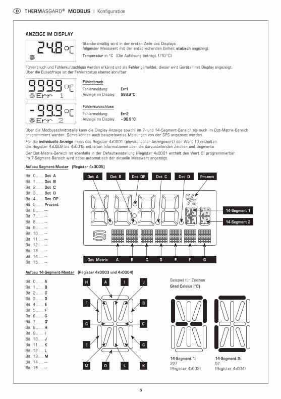
ANZEIGE IM DISPLAY
Standardmäßig wird in der ersten Zeile des Displays folgender Messwert mit der entsprechenden Einheit statisch angezeigt:
Temperatur in °C (Die Auflösung beträgt 1/10 °C)
Fühlerbruch und Fühlerkurzschluss werden erkannt und als Fehler gemeldet, dieser wird Geräten mit Display angezeigt. Über die Busabfrage ist der Fehlerstatus ebenso abrufbar.
Fühlerbruch
Fehlermeldung: Err1 Anzeige im Display: 999.9 °C
Fühlerkurzschluss
Fehlermeldung: Err2 Anzeige im Display: – 99.9 °C
Über die Modbusschnittstelle kann die Display-Anzeige sowohl im 7- und 14-Segment-Bereich als auch im Dot-Matrix-Bereich programmiert werden. Somit können auch beispielsweise Meldungen von der SPS angezeigt werden.
Für die individuelle Anzeige muss das Register 4x0001 (physikalischer Anzeigewert) den Wert 10 enthalten. Die Register 4x0002 bis 4x0012 enthalten Informationen über die darzustellenden Zeichen und Segmente.
Der Dot-Matrix-Bereich ist ebenfalls in der Defaulteinstellung (Register 4x0001 enthält den Wert 0) programmierbar. Im 7-Segment-Bereich wird dabei automatisch der aktuelle Messwert angezeigt.
13 Zähler Exception-Meldungen Unsigned 16 Bit Fehlerzähler
14 Zähler Slave-Telegramme Unsigned 16 Bit Slave-Telegramme
15 Zähler Telegramme ohne Antwort Unsigned 16 Bit Broadcastmeldungen (Adresse 0)
Function 17 Report Slave ID Aufbau Antworttelegramm
Byte Nr. Parameter Data Type Antwort
00 Byteanzahl Unsigned 8 Bit 6
01 Slave ID (Device Typ) Unsigned 8 Bit 2 = THERMASGARD® MODBUS
02 Slave ID (Device Class) Unsigned 8 Bit 10 = THERMASGARD® / THERMASREG®
03 Status Unsigned 8 Bit 255 = RUN, 0 = STOP
04 Versionsnummer (Release) Unsigned 8 Bit 1...9
05 Versionsnummer (Version) Unsigned 8 Bit 1…99
06 Versionsnummer (Index) Unsigned 8 Bit 1
D THERMASGARD® MODBUS | Telegramme
8
D THERMASGARD® MODBUS | Installation
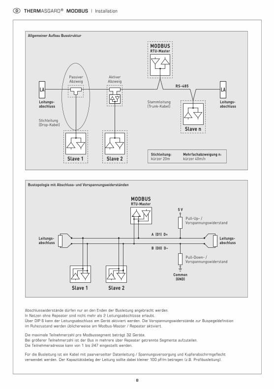
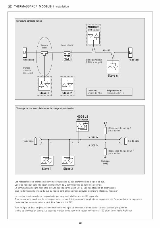
Allgemeiner Aufbau Busstruktur
Bustopologie mit Abschluss- und Vorspannungswiderständen
Abschlusswiderstände dürfen nur an den Enden der Busleitung angebracht werden. In Netzen ohne Repeater sind nicht mehr als 2 Leitungsabschlüsse erlaubt. Über DIP 6 kann der Leitungsabschluss am Gerät aktiviert werden. Die Vorspannungswiderstände zur Buspegeldefinition im Ruhezustand werden üblicherweise am Modbus-Master / Repeater aktiviert.
Die maximale Teilnehmerzahl pro Modbussegment beträgt 32 Geräte. Bei größerer Teilnehmerzahl ist der Bus in mehrere über Repeater getrennte Segmente aufzuteilen. Die Teilnehmeradresse kann von 1 bis 247 eingestellt werden.
Für die Busleitung ist ein Kabel mit paarverseilter Datenleitung / Spannungsversorgung und Kupferabschirmgeflecht verwendet werden. Der Kapazitätsbelag der Leitung sollte dabei kleiner 100 pF/m betragen (z.B. Profibusleitung).
Slave n
MODBUSRTU-Master
RS-485
Leitungs-abschluss
Leitungs-abschluss
AktiverAbzweig
PassiverAbzweig
Stichleitung(Drop-Kabel)
Stammleitung(Trunk-Kabel)
Stichleitung:kürzer 20m
Mehrfachabzweigung n:kürzer 40m/n
Allgemeiner Aufbau Busstruktur
Slave 1 Slave 2
LA LA
Bustopologie mit Abschluss- und Vorspannungswiderständen
A (D1) D+
5 V
Common(GND)
B (D0) D–
Leitungs-abschluss
Leitungs-abschluss
Pull-Down- /Vorspannungswiderstand
Pull-Up- /Vorspannungswiderstand
MODBUSRTU-Master
Slave 1 Slave 2
9
Die Geräte sind im spannungslosen Zustand anzuschließen. Der Anschluss der Geräte darf nur an Sicherheitskleinspannung er folgen. Folgeschäden, welche durch Fehler an diesem Gerät entstehen, sind von der Gewährleistung und Haftung ausgeschlossen. Die Installation der Geräte darf nur durch autorisiertes Fach personal erfolgen. Es gelten ausschließlich die technischen Daten und Anschlussedingungen der zum Gerät gelieferten Geräte etikettdaten, der Mon tage- und Bedienungsanleitung. Abweichungen zur Katalog dar stellung sind nicht zusätzlich auf geführt und im Sinne des technischen Fortschritts und der stetigen Verbesserung unserer Produkte möglich. Bei Verände-rungen der Geräte durch den Anwender entfallen alle Gewährleistungs- an sprüche. Der Betrieb in der Nähe von Geräten, welche nicht den EMV-Richtlinien entsprechen, kann zur Beeinflussung der Funktions-weise führen. Dieses Gerät darf nicht für Überwachungszwecke, welche dem Schutz von Personen gegen Gefährdung oder Verletzung dienen und nicht als NOT-AUS-Schalter an Anlagen und Maschinen oder vergleichbare sicherheitsrelevante Aufgaben verwendet werden.
Die Gehäuse- und Gehäusezubehörmaße können geringe Toleranzen zu den Angaben dieser Anleitung aufweisen.
Veränderungen dieser Unterlagen sind nicht gestattet.
Bei Reklamationen werden nur vollständige Geräte in Original ver-packung angenommen.
Hinweise zum mechanischen Ein- und Anbau:
Der Einbau hat unter Berücksichtigung der einschlägigen, für den Messort gültigen Vorschriften und Standards (wie z. B. Schweiß vor-schriften usw.) zu erfolgen. Insbesondere sind zu berücksichtigen:
– VDE ⁄ VDI Technische Temperaturmessungen, Richtlinie, Mess an ordnungen für Temperaturmessungen
– die EMV-Richtlinien, diese sind einzuhalten
– eine Parallelverlegung mit stromführenden Leitungen ist unbedingt zu vermeiden
– es wird empfohlen abgeschirmte Leitungen zu verwenden, dabei ist der Schirm einseitig an der DDC ⁄ SPS aufzulegen.
Der Einbau hat unter Beachtung der Übereinstimmung der vor-liegenden technischen Parameter der Thermometer mit den realen Einsatzbedingungen zu erfolgen, insbesondere:– Messbereich– zulässiger maximaler Druck, Strömungsgeschwindigkeit– Einbaulänge, Rohrmaße– Schwingungen, Vibrationen, Stöße sind zu vermeiden (< 0,5 g)Achtung! Berücksichtigen Sie in jedem Fall die mechanischen und thermischen Belastungsgrenzen der Schutzrohre nach DIN 43763 bzw. nach speziellen S+S-Standards!
Hinweise zum Prozessanschluss von Einbaufühlern:Wählen Sie den Werkstoff des Schutzrohres so aus, dass er möglichst mit dem Werkstoff der Rohrleitung oder der Behälterwand überein-stimmt, in die das Thermometer eingebaut wird!Die Maximaltemperatur Tmax und der Maximaldruck pmax liegen bei:TH-ms Messinghülsen bei +150 °C, pmax = 10 bar, und TH-VA Edelstahlhülsen (Standard) bei +400 °C, pmax = 40 bar.
Einschraubgewinde:Achten Sie beim Einbau auf die sachgemäße Unterlage der Dichtung oder des Abdichtmaterials! Bei Einschraubgewinde gelten für das Anzugsdrehmoment folgende zulässige Richtwerte:M 18 x 1,5; M 20 x 1,5; G ½ " : 50 Nm M 27 x 2,0; G ¾ " : 100 Nm
Flanschbefestigung:Bei Flanschbefestigungen sind die Schrauben am Flanschteil gleich-mäßig anzuziehen. Die seitliche Druckschraube muss sicher klemmen, sonst kann es zum Durchrutschen des Fühlerschaftes kommen.
Einschweißhülsen:Es sind spezielle Schweißvorschriften zu beachten. Prinzipiell dürfen keine Unebenheiten oder ähnliches an Schweißstellen entstehen, die die „CIP-Fähigkeit“ der Anlage beeinflussen.Bei hochdruckführenden Leitungen sind Druckabnahmen und Über-wachungen erforderlich.
D Montage und Installation
D Wichtige Hinweise
Als AGB gelten ausschließlich unsere sowie die gültigen „Allgemeinen Lieferbedingungen für Erzeugnisse und Leistungen der Elektro industrie“ (ZVEI Bedingungen) zuzüglich der Ergänzungsklausel „Erweiterter Eigentumsvorbehalt“.
Außerdem sind folgende Punkte zu beachten:
– Der Anschluss der Geräte darf nur an Sicherheitskleinspannung und im spannungslosen Zustand erfolgen. Um Schäden und Fehler am Gerät (z.B. durch Spannungsinduktion) zu verhindern, sind abgeschirmte Leitungen zu verwenden, eine Parallelverlegung zu stromführenden Leitungen zu vermeiden und die EMV- Richtlinien zu beachten.
– Dieses Gerät ist nur für den angegebenen Verwendungszweck zu nutzen, dabei sind die entsprechenden Sicherheitsvorschriften des VDE, der Länder, ihrer Überwachungsorgane, des TÜV und der örtlichen EVU zu beachten. Der Käufer hat die Einhaltung der Bau- und Sicherungsbestimmung zu gewährleisten und Gefährdungen aller Art zu vermeiden.
– Für Mängel und Schäden, die durch unsachgemäße Verwendung dieses Gerätes entstehen, werden keinerlei Gewährleistungen und Haftungen übernommen.
– Folgeschäden, welche durch Fehler an diesem Gerät entstehen, sind von der Gewährleistung und Haftung ausgeschlossen.
– Die Installation der Geräte darf nur durch Fachpersonal erfolgen.
– Es gelten ausschließlich die technischen Daten und Anschlussbedingungen der zum Gerät gelieferten Montage- und Bedienungs anleitung, Abweichungen zur Katalogdarstellung sind nicht zusätzlich aufgeführt und im Sinne des technischen Fortschritts und der stetigen Verbesserung unserer Produkte möglich.
– Bei Veränderungen der Geräte durch den Anwender entfallen alle Gewährleistungsansprüche.
– Dieses Gerät darf nicht in der Nähe von Wärmequellen (z.B. Heizkörpern) oder deren Wärmestrom eingesetzt werden, eine direkte Sonnen-einstrahlung oder Wärmeeinstrahlung durch ähnliche Quellen (starke Leuchte, Halogenstrahler) ist unbedingt zu vermeiden.
– Der Betrieb in der Nähe von Geräten, welche nicht den EMV- Richtlinien entsprechen, kann zur Beeinflussung der Funktionsweise führen.
– Dieses Gerät darf nicht für Überwachungszwecke, welche dem Schutz von Personen gegen Gefährdung oder Verletzung dienen und nicht als Not-Aus-Schalter an Anlagen und Maschinen oder vergleichbare sicherheitsrelevante Aufgaben verwendet werden.
– Die Gehäuse- und Gehäusezubehörmaße können geringe Toleranzen zu den Angaben dieser Anleitung aufweisen.
– Veränderungen dieser Unterlagen sind nicht gestattet.
– Reklamationen werden nur vollständig in Originalverpackung angenommen.
Vor der Installation und Inbetriebnahme ist diese Anleitung zu lesen und die alle darin gemachten Hinweise sind zu beachten!
10
Schematic diagram THERMASGARD® MODBUS
G THERMASGARD® MODBUS | Configuration
1 2 3 4 5
12345678
ON DIP A
123456
ON DIP B
modeoffset
Plug for display
–UB
GN
DSh
ield
ing
RS4
85 M
odbu
s A
RS4
85 M
odbu
s B
+UB
24V
AC
/DC Plug for display
contact ison the right side
DIP A: Bus address DIP B: Bus parameters(Baud rate, parity ...)Telegram indicator Reception (LED green) Error (LED red)
LED (internal status)
Offset correctiontemperature: ± 10°C
Calibrateable temperature sensors with Modbus connection. For more information, please refer to device-specific instructions.
TECHNICAL DATA
Voltage supply: 24 V AC (± 20 %) and 15...36 V DC (± 10 %)
Power consumption: < 1 VA ⁄ 24 V DC < 2.2 VA ⁄ 24 V AC
Sensor: Pt1000 (according to DIN EN 60751, class B)
Measuring range: – 50...+ 150 °C depending on the type of device
Temperature deviation: ± 0.2 K at +25 °C
Zero point offset: ± 10 °C
Ambient temperature: – 30...+ 70 °C
Medium: clean air and non-aggressive, non-combustible gases
Bus parameters: In the absence of current delivery (under currentless conditions) can be configured and addressed via DIP switch!
Bus interface: RS 485, galvanically isolated, Bus termination activatable via DIP switches.
Up to 32 devices possible in one segment. In case of a greater number of devices, RS485 transceivers must be used.
Bus protocol: Modbus (RTU mode), address range 0...247 selectable
Baud rate: 9600, 19200, 38400 Baud
Status indicator: LED green = Telegram valid LED red = Telegram error
Error detection: sensor breakage, sensor short circuit
Signal filtering: 0.3 s / 1 s / 10 s
Display: The Modbus interface allows the display screen to be individually configured, both in the 7 and 14 segment range and in the dot-matrix range.
Display - individually programmable
Zero point calibration
The sensors are preset and calibrated at the factory. Adjustment is possible using the two offset potentiometers. Range of adjustment: approx. ± 10 °C.
11
G THERMASGARD® MODBUS | Configuration
BUS ADDRESS
Bus address (binary coded, value selectable from 1 to 247)
MODBUS
DIP switch [A]
DIP 1 DIP 2 DIP 3 DIP 4 DIP 5 DIP 6 DIP 7 DIP 8
1 2 3 4 5 6 7 8
ON DIP A128 64 32 16 8 4 2 1
O N O N OFF OFF OFF OFF OFF O N
Example shows 128 + 64 + 1 = 193 as Modbus address.
The device address in the range of 1 to 247 is set at DIP switch [A]. For switch positions 1 to 8 see the table on the back!
Address 0 is reserved for broadcast messages. Addresses greater than 247 must not be assigned and are ignored by the device. The DIP switches are binary-coded with the following values:
DIP 1 = 128 ............ DIP 1 = ON DIP 2 = 64 ............ DIP 2 = ON DIP 3 = 32 ............ DIP 3 = OFF DIP 4 = 16 ............ DIP 4 = OFF DIP 5 = 8 ............ DIP 5 = OFF DIP 6 = 4 ............ DIP 6 = OFF DIP 7 = 2 ............ DIP 7 = OFF DIP 8 = 1 ............ DIP 8 = ON The switch positions shown here results in the Modbus address 128 + 64 + 1 = 193
BUS PARAMETERS
Baud rate (selectable)
DIP 1
DIP 2
MODBUSDIP switch [B]
9600 baud O N OFF
1 2 3 4 5 6
ON DIP B19200 baud O N O N
38400 baud OFF O N
Reserved OFF OFF
Parity (selectable)
DIP 3
Parity check (on / off)
DIP 4
8N1-Modus (on / off)
DIP 5
Bus termination (on / off)
DIP 6
EVEN (numbered) O N Active
(1 stop bit) O N Active O N Aktive O N
ODD (numbered) OFF Inactive (no parity)
(2 stop bits) OFF Inactive (default) OFF Inaktive OFF
The baud rate (speed of transmission) is set at DIP switches 1 and 2 of DIP switch block [B]. Selectable are 9600 baud, 19200 baud, or 38400 baud – see table!
Parity is set at DIP switch 3 of DIP switch block [B]. Selectable are EVEN or ODD – see table!
Parity check is activated via DIP switch 4 of DIP switch block [B]. Selectable are active (1 stop bit), or inactive (2 stop bits), i.e. no parity check – see table!
The 8N1 mode is activated via DIP switch 5 of DIP switch block [B]. The functionality of DIP switch 3 (parity) and DIP switch 4 (parity check) of DIP switch block [B] is therefore deactivated. Selectable are 8N1 active or inactive (default) – see table !.
Bus termination is activated via DIP switch 6 of DIP switch block [B]. Selectable are active (bus termination resistance of 120 Ohm), or inactive (no bus termination) – see table!
When bus parameters and bus address are changed at devices with display, the respective settings are shown on the display for approx. 30 seconds.
COMMUNICATION INDICATORCommunication is indicated via two LEDs. Error-free received telegrams are signalized by the green LED lighting up, regardless of the device address. Faulty telegrams or triggered Modbus exception telegrams are depicted by the red LED lighting up.
DIAGNOSTICSAn error diagnostic function is integrated
12
G THERMASGARD® MODBUS | Configuration
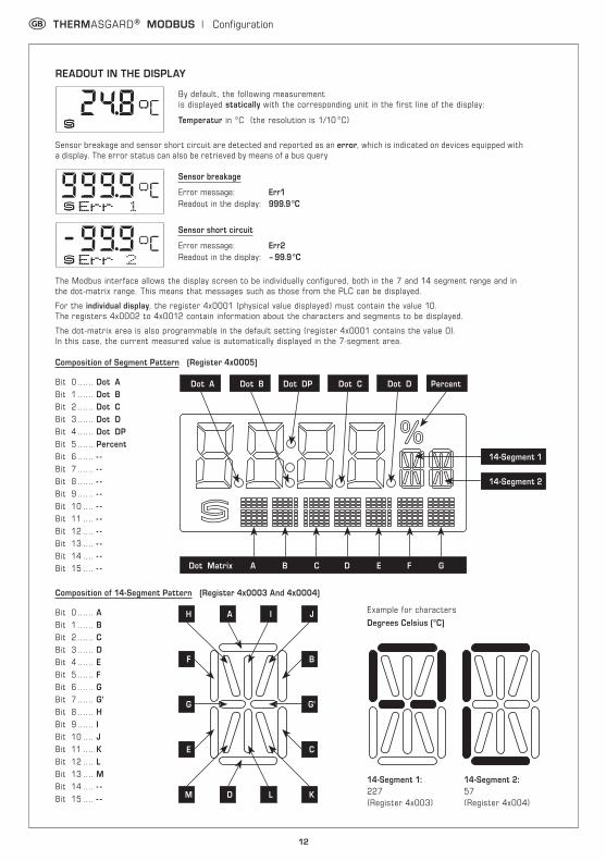
READOUT IN THE DISPLAY
By default, the following measurement is displayed statically with the corresponding unit in the first line of the display:
Temperatur in °C (the resolution is 1/10 °C)
Sensor breakage and sensor short circuit are detected and reported as an error, which is indicated on devices equipped with a display. The error status can also be retrieved by means of a bus query
Sensor breakage
Error message: Err1 Readout in the display: 999.9 °C
Sensor short circuit
Error message: Err2 Readout in the display: – 99.9 °C
The Modbus interface allows the display screen to be individually configured, both in the 7 and 14 segment range and in the dot-matrix range. This means that messages such as those from the PLC can be displayed.
For the individual display, the register 4x0001 (physical value displayed) must contain the value 10. The registers 4x0002 to 4x0012 contain information about the characters and segments to be displayed.
The dot-matrix area is also programmable in the default setting (register 4x0001 contains the value 0). In this case, the current measured value is automatically displayed in the 7-segment area.
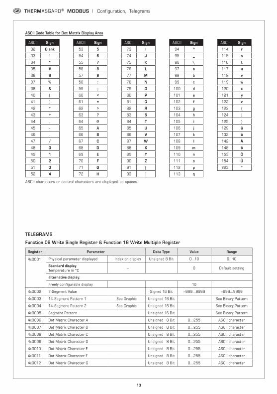
11 Counter bus telegrams Unsigned 16 Bit All valid bus telegrams
12 Counter communication errors (Parity, CRC, frame errors, etc.) Unsigned 16 Bit Faulty bus telegrams
13 Counter exception telegrams Unsigned 16 Bit Error counter
14 Counter slave telegrams Unsigned 16 Bit Slave telegrams
15 Counter telegrams without answer Unsigned 16 Bit Broadcast messages (address 0)
Function 17 Report Slave ID Composition of answer telegram
Byte No. Parameter Data Type Answer
00 Number of bytes Unsigned 8 Bit 6
01 Slave ID (device type) Unsigned 8 Bit 2 = THERMASGARD® MODBUS
02 Slave ID (device class) Unsigned 8 Bit 10 = THERMASGARD® / THERMASREG®
03 Status Unsigned 8 Bit 255 = RUN, 0 = STOP
04 Version number (release) Unsigned 8 Bit 1...9
05 Version number (version) Unsigned 8 Bit 1…99
06 Version number (index) Unsigned 8 Bit 1
15
General layout of bus structure
Bus topology with terminating and bias resistors
Terminating resistor may only be installed at the ends of the bus line. In networks with repeaters not more than two line terminations are allowed. Line termination at the device can be activated via DIP switch 6. The bias resistors for bus level definition in the resting state are usually activated at the Modbus master / repeater.
The maximum number of subscribers per Modbus segment is 32 devices. When the number of subscribers is greater, the bus must be subdivided into several segments separated by repeaters. The subscriber address can be set from 1 to 247.
For the bus line, a twisted-pair cable data line / power supply line and copper mesh wire shield must be used. Therefore, the line capacitance should be less than 100 pF / m (e.g. Profibus cable).
G THERMASGARD® MODBUS | Installation
Slave n
MODBUSRTU-Master
RS-485
Linetermination
Linetermination
Active branch
Passivebranch
Stub line
Trunk line
Stub line:shorter 20m
Multiple branch n:shorter 40m/n
General layout of bus structure
Slave 1 Slave 2
LA LA
Bus topology with terminating and bias resistors
A (D1) D+
5 V
Common(GND)
B (D0) D–
Linetermination
Linetermination
Pull-down /bias resistor
Pull-up /bias resistor
MODBUSRTU-Master
Slave 1 Slave 2
16
G Important notes
Our “General Terms and Conditions for Business“ together with the “General Conditions for the Supply of Products and Services of the Electrical and Electronics Industry“ (ZVEI conditions) including supplementary clause “Extended Retention of Title“ apply as the exclusive terms and conditions.
In addition, the following points are to be observed:
– Devices must only be connected to safety extra-low voltage and under dead-voltage condition. To avoid damages and errors at the device (e.g. by voltage induction) shielded cables are to be used, laying parallel with current-carrying lines is to be avoided, and EMC directives are to be observed.
– This device shall only be used for its intended purpose. Respective safety regulations issued by the VDE, the states, their control authorities, the TÜV and the local energy supply company must be observed. The purchaser has to adhere to the building and safety regulations and has to prevent perils of any kind.
– No warranties or liabilities will be assumed for defects and damages arising from improper use of this device.
– Consequential damages caused by a fault in this device are excluded from warranty or liability.
– These devices must be installed by authorised specialists only.
– The technical data and connecting conditions of the mounting and operating instructions delivered together with the device are exclusively valid. Deviations from the catalogue representation are not explicitly mentioned and are possible in terms of technical progress and continuous improvement of our products.
– In case of any modifications made by the user, all warranty claims are forfeited.
– This device must not be installed close to heat sources (e.g. radiators) or be exposed to their heat flow. Direct sun irradiation or heat irradiation by similar sources (powerful lamps, halogen spotlights) must absolutely be avoided.
– Operating this device close to other devices that do not comply with EMC directives may influence functionality.
– This device must not be used for monitoring applications, which serve the purpose of protecting persons against hazards or injury, or as an EMERGENCY STOP switch for systems or machinery, or for any other similar safety-relevant purposes.
– Dimensions of enclosures or enclosure accessories may show slight tolerances on the specifications provided in these instructions.
– Modifications of these records are not permitted.
– In case of a complaint, only complete devices returned in original packing will be accepted.
These instructions must be read before installation and putting in operation and all notes provided therein are to be regarded!
G Mounting and Installation
Devices are to be connected under dead-voltage condition. Devices must only be connected to safety extra-low voltage. Consequential damages caused by a fault in this device are excluded from warranty or liability. Installation of these devices must only be realized by authorized qualified personnel. The technical data and connecting conditions shown on the device labels and in the mounting and operating instructions delivered together with the device are exclusively valid. Deviations from the catalogue representation are not explicitly mentioned and are possible in terms of technical progress and continuous improvement of our products. In case of any modifications made by the user, all warranty claims are forfeited. Operating this device close to other devices that do not comply with EMC directives may influence functionality. This device must not be used for monitoring applications, which serve the purpose of protecting persons against hazards or injury, or as an EMERGENCY STOP switch for systems or machinery, or for any other similar safety-relevant purposes.
Dimensions of enclosures or enclosure accessories may show slight tolerances on the specifications provided in these instructions.
Modifications of these records are not permitted.
In case of a complaint, only complete devices returned in original packing will be accepted.
Notes regarding mechanical mounting and attachment:
Mounting shall take place while observing all relevant regulations and standards applicable for the place of measurement (e.g. such as welding instructions, etc.). Particularly the following shall be regarded:
– VDE ⁄ VDI directive technical temperature measurements, measurement set - up for temperature measurements.
– The EMC directives must be adhered to.
– It is imperative to avoid parallel laying of current-carrying lines.
– We recommend to use shielded cables with the shielding being attached at one side to the DDC ⁄ PLC.
Before mounting, make sure that the existing thermometer‘s technical parameters comply with the actual conditions at the place of utilization, in particular in respect of:– Measuring range – Permissible maximum pressure, flow velocity – Installation length, tube dimensions– Oscillations, vibrations, shocks are to be avoided (< 0.5 g)Attention! In any case, please observe the mechanical and thermal load limits of protective tubes according to DIN 43763 respectively according to specific S+S standards!
Notes regarding process connection of built-in sensors: If possible, select material of protective tube to match the material of piping or tank wall, in which the thermometer will be installed!Maximum temperatures Tmax and maximum pressures pmax are as follows: for TH - MS brass sleeves Tmax = +150 °C, pmax = 10 bar and for TH - VA stainless steel sleeves (standard) Tmax = +400 °C, pmax = 40 bar.
Screw-in threads:Ensure appropriate support of the gasket or sealing material when mounting! Permissible tightening torque standard values for screw - in threads, are as follows:M 18 x 1.5; M 20 x 1.5; pipe thread G ½ " : 50 Nm M 27 x 2.0; pipe thread G ¾ " : 100 Nm
Flange mounting:In case of flange mounting, screws in the flange part must be equally tightened. The lateral pressure screw must clamp securely, otherwise the feeler shaft might slip through.
Welding sleeves:Specific welding instructions shall be observed. On principle, unevenness or the like that might influence the system‘s ”CIP ability“ must not develop at welds. For high-pressure lines, pressure test certifications and inspections are required.
17
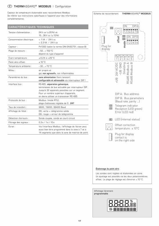
Schéma de raccordement THERMASGARD® MODBUS
F THERMASGARD® MODBUS | Configuration
Capteur de température étalonnable avec raccordement Modbus. Se référer aux instructions spécifiques à l'appareil pour des informations complémentaires.
CARACTÉRISTIQUES TECHNIQUES
Tension d’alimentation : 24 V ca (± 20 %) et 15...36 V cc (± 10 %)
Consommation électrique : < 1 VA ⁄ 24 V cc < 2,2 VA ⁄ 24 V ca
Capteur : Pt1000 (selon la norme DIN EN 60751, classe B)
Plage de mesure : – 50...+ 150 °C dépend du type d'appareil
Écart température : ± 0,2 K à +25 °C
Point zéro offset: ± 10 °C
Température ambiante : – 30...+ 70 °C
Milieu : air propre et gaz non agressifs, non inflammables
Paramètres du bus : sans alimentation (hors tension), configurable et adressable via interrupteur DIP !
Interface bus : RS 485, séparation galvanique, terminaison de bus activable par interrupteur DIP. Jusqu'à 32 appareils possibles sur un segment. Pour un nombre supérieur d'appareils, on devra utiliser un transceiver RS 485.
Protocole de bus : Modbus (mode RTU), plage d'adresses réglable de 0...247
Taux de transfert : 9600, 19200, 38400 Baud
Affichage de l'état : DEL verte = télégramme valide DEL rouge = erreur de télégramme
Détection d'erreurs : Sonde coupée, sonde en court-circuit
Filtrage des signaux : 0,3 s / 1 s / 10 s
Écran : Via l'interface Modbus, l'affichage de l'écran peut aussi bien être programmé dans la zone à 7 et à 14 segments que dans la zone de matrice de point
1 2 3 4 5
12345678
ON DIP A
123456
ON DIP B
modeoffset
Plug for display
–UB
GN
DSh
ield
ing
RS4
85 M
odbu
s A
RS4
85 M
odbu
s B
+UB
24V
AC
/DC Plug for display
contact ison the right side
DIP A: Bus address DIP B: Bus parameters(Baud rate, parity ...)Telegram indicator Reception (LED green) Error (LED red)
LED (internal status)
Offset correctiontemperature: ± 10°C
Affichage librement programmable
Étalonnage du point zéro
Les sondes sont réglées et étalonnées en usine. Un ajustage est possible via les deux potentiomètres offset. La plage de réglage est d'environ ± 10 °C.
18
F THERMASGARD® MODBUS | Configuration
ADRESSE DU BUS
Adresse du bus (code binaire, valance réglable de 1 à 247)
MODBUS
Interrupteur DIP [A]
DIP 1 DIP 2 DIP 3 DIP 4 DIP 5 DIP 6 DIP 7 DIP 8
1 2 3 4 5 6 7 8
ON DIP A128 64 32 16 8 4 2 1
O N O N OFF OFF OFF OFF OFF O N
suit l'adresse Modbus 128 + 64 + 1 = 193
L'adresse de l'appareil dans une plage de 1 à 247 (format binaire) est réglée via l'interrupteur DIP [A]. Position interrupteur 1 à 8 – voir tableau au verso !
L'adresse 0 est réservée pour des messages de broadcast, les adresses dépassant 247 ne doivent pas être occupées et sont ignorées par l'appareil. Les interrupteurs DIP sont codés en binaire avec les valences suivantes :
DIP 1 = 128 ............ DIP 1 = ON DIP 2 = 64 ............ DIP 2 = ON DIP 3 = 32 ............ DIP 3 = OFF DIP 4 = 16 ............ DIP 4 = OFF DIP 5 = 8 ............ DIP 5 = OFF DIP 6 = 4 ............ DIP 6 = OFF DIP 7 = 2 ............ DIP 7 = OFF DIP 8 = 1 ............ DIP 8 = ON L'exemple montre 128 + 64 + 1 = 193 comme adresse Modbus.
PARAMÈTRES DU BUS
Taux de transfert (réglable)
DIP 1
DIP 2
MODBUSInterrupteur DIP [B]
9600 Baud O N OFF
1 2 3 4 5 6
ON DIP B19200 Baud O N O N
38400 Baud OFF O N
réservé OFF OFF
Parité (réglable)
DIP 3
Protection par parité (on / off)
DIP 4
8N1-Modus (on / off)
DIP 5
Terminaison de bus (on / off)
DIP 6
EVEN (pair) O N actif
(1 bit stop) O N actif O N actif O N
ODD (impair) OFF inactif
(2 bit stop) OFF inactif (par défaut) OFF inactif OFF
Le taux de Baud (vitesse de transfert) est réglé via les pos. 1 et 2 de l'interrupteur DIP [B]. On peut régler 9600 Baud, 19200 Baud ou 38400 Baud – voir tableau !
La parité est réglée via la pos. 3 de l'interrupteur DIP [B]. On peut régler EVEN (paire) ou ODD (impaire) – voir tableau !
La protection par parité (sécurité par parité) est activée via la pos. 4 de l'interrupteur DIP [B]. On peut régler une correction d'erreur (sécurisation par parité) active (1 bit d'arrêt) ou inactive (2 bits d'arrêt), c.-à.-d. aucune sécurisation par parité – voir tableau !
Le mode 8N1 est activé via la pos. 5 de l'interrupteur DIP [B]. Le fonctionnement de la pos. 3 (parité) et de la pos. 4 (protection par parité) de l'interrupteur DIP [B] est ainsi désactivé. 8N1 est réglable en mode actif ou inactif (par défaut) – voir tableau !
La terminaison du bus est activée par la pos. 6 de l'interrupteur DIP [B]. On peut régler active (résistance de terminaison de bus de 120 Ohm) ou inactive (pas de terminaison de bus) – voir tableau !
En cas de modification des paramètres du bus et de l'adresse du bus, les appareils avec affichage sur écran affichent les paramètres correspondants à l'écran pour env. 30 secondes.
AFFICHAGE DE COMMUNICATIONLa communication est signalée par deux voyants DEL. Les télégrammes dont la réception est bonne sont signalés indépendamment de l'adresse de l'appareil par l'allumage du voyant vert. Les télégrammes erronés ou les télégrammes d'exception Modbus déclenchés sont représentés par l'allumage du voyant rouge.
DIAGNOSTICLa fonction de diagnostic de défauts est intégrée
19
F THERMASGARD® MODBUS | Configuration
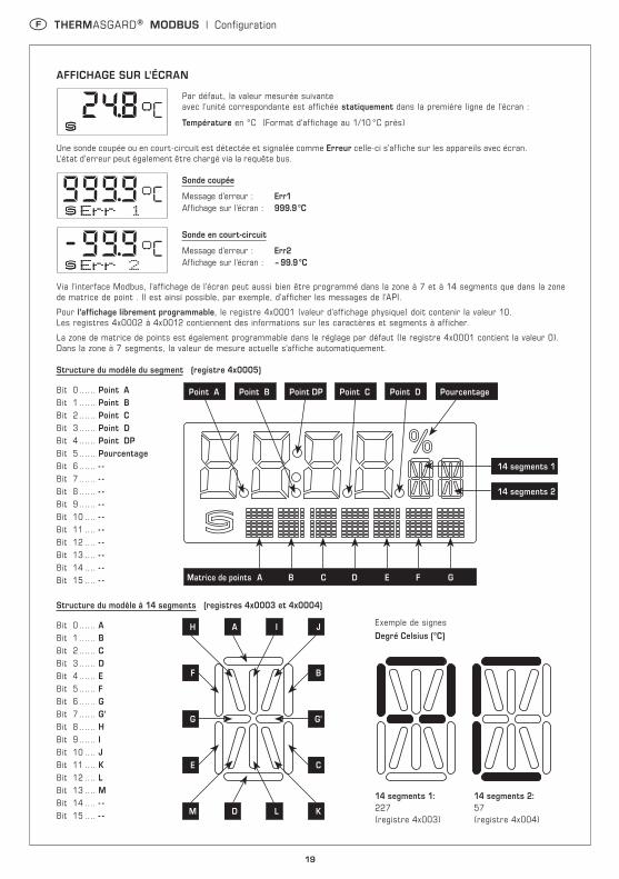
AFFICHAGE SUR L'ÉCRAN
Par défaut, la valeur mesurée suivante avec l'unité correspondante est affichée statiquement dans la première ligne de l'écran :
Température en °C (Format d'affichage au 1/10 °C près)
Une sonde coupée ou en court-circuit est détectée et signalée comme Erreur celle-ci s'affiche sur les appareils avec écran. L'état d'erreur peut également être chargé via la requête bus.
Sonde coupée
Message d'erreur : Err1 Affichage sur l'écran : 999.9 °C
Sonde en court-circuit
Message d'erreur : Err2 Affichage sur l'écran : – 99.9 °C
Via l'interface Modbus, l'affichage de l'écran peut aussi bien être programmé dans la zone à 7 et à 14 segments que dans la zone de matrice de point . Il est ainsi possible, par exemple, d'afficher les messages de l'API.
Pour l'affichage librement programmable, le registre 4x0001 (valeur d'affichage physique) doit contenir la valeur 10. Les registres 4x0002 à 4x0012 contiennent des informations sur les caractères et segments à afficher.
La zone de matrice de points est également programmable dans le réglage par défaut (le registre 4x0001 contient la valeur 0). Dans la zone à 7 segments, la valeur de mesure actuelle s'affiche automatiquement.
Topologie du bus avec résistances de charge et polarisation
Les résistances de charges ne doivent être placées qu'aux extrémités de la ligne de bus. Dans les réseaux sans repeater, un maximum de 2 terminaisons de ligne est autorisé. La terminaison de ligne peut être activée sur l'appareil via le DIP 6. Les résistances de polarisation pour la définition du niveau du bus au repos sont généralement activées au maître Modbus / repeater.
Le nombre maximum de correspondants par segment Modbus est de 32 appareils. Pour des grands nombres de correspondants, le bus doit être réparti en plusieurs segments par l'intermédiaire de repeaters. L'adresse des correspondants peut être fixée de 1 à 247.
Pour la ligne de bus, on peut utiliser un câble avec ligne de données / alimentation tension câblées par paire et treillis de blindage en cuivre. La capacité linéique de la ligne doit rester inférieure à 100 pF/m (p.ex. ligne Profibus).
Slave n
MODBUSRTU-Master
RS-485
Fin de ligneFin de ligne
Raccord actifRaccord passif
Tronçon(câble de dérivation)
Ligne principale(câble principal)
Tronçon :moins de 20 m
Poly-raccord n :moins de 40 m / n
Structure générale du bus
Slave 1 Slave 2
LA LA
Topologie du bus avec résistances de charge et polarisation
A (D1) D+
5 V
Common(GND)
B (D0) D–
Fin de ligneFin de ligne
Résistance de pull-down / polarisation
Résistance de pull-up / polarisation
MODBUSRTU-Master
Slave 1 Slave 2
23
F Généralités
Seules les CGV de la société S+S, les « Conditions générales de livraison du ZVEI pour produits et prestations de l’industrie électronique » ainsi que la clause complémentaire « Réserve de propriété étendue » s’appliquent à toutes les relations commerciales entre la société S+S et ses clients.
Il convient en outre de respecter les points suivants :
– Les raccordements électriques doivent être exécutés HORS TENSION. Ne branchez l’appareil que sur un réseau de très basse tension de sécurité. Pour éviter des endommagements ⁄ erreurs sur l’appareil (par ex. dus à une induction de tension parasite), il est conseillé d’utiliser des câbles blindés, ne pas poser les câbles de sondes en parallèle avec des câbles de puissance, les directives CEM sont à respecter.
– Cet appareil ne doit être utilisé que pour l’usage qui est indiqué en respectant les règles de sécurité correspondantes de la VDE, des Länders, de leurs organes de surveillance, du TÜV et des entreprises d’approvisionnement en énergie locales. L’acheteur doit respecter les dispositions relatives à la construction et à la sécurité et doit éviter toutes sortes de risques.
– Nous déclinons toute responsabilité ou garantie pour les défauts et dommages résultant d’une utilisation inappropriée de cet appareil.
– Nous déclinons toute responsabilité ou garantie au titre de tout dommage consécutif provoqué par des erreurs commises sur cet appareil.
– L’installation des appareils doit être effectuée uniquement par un spécialiste qualifié.
– Seules les données techniques et les conditions de raccordement indiquées sur la notice d’instruction accompagnant l’appareil sont applicables, des différences par rapport à la présentation dans le catalogue ne sont pas mentionnées explicitement et sont possibles suite au progrès technique et à l’amélioration continue de nos produits.
– En cas de modifications des appareils par l’utilisateur, tous droits de garantie ne seront pas reconnus.
– Cet appareil ne doit pas être utilisé à proximité des sources de chaleur (par ex. radiateurs) ou de leurs flux de chaleur, il faut impérativement éviter un ensoleillement direct ou un rayonnement thermique provenant de sources similaires (lampes très puissantes, projecteurs à halogène).
– L’utilisation de l’appareil à proximité d’appareils qui ne sont pas conformes aux directives « CEM » pourra nuire à son mode de fonctionnement.
– Cet appareil ne devra pas être utilisé à des fins de surveillance qui visent à la protection des personnes contre les dangers ou les blessures ni comme interrupteur d’arrêt d’urgence sur des installations ou des machines ni pour des fonctions relatives à la sécurité comparables.
– Il est possible que les dimensions du boîtier et des accessoires du boîtier divergent légèrement des indications données dans cette notice.
– Il est interdit de modifier la présente documentation.
– En cas de réclamation, les appareils ne sont repris que dans leur emballage d’origine et si tous les éléments de l’appareil sont complets.
Avant de procéder à toute installation et à la mise en service, veuillez lire attentivement la présente notice et toutes les consignes qui y sont précisées !
F Montage et installation
Les raccordements électriques doivent être exécutés HORS TENSION. Veillez à ne brancher l’appareil que sur un réseau de très basse tension de sécurité. Nous déclinons toute responsabilité ou garantie au titre de tout dommage consécutif provoqué par des erreurs commises sur cet appareil. L’installation des appareils ne doit être effectuée que par du personnel qualifié et autorisé. Seules les données techniques et les conditions de raccordement indiquées sur l’étiquette signalétique de l’appareil ainsi que la notice d’instruction sont applicables. Des différences par rapport à la présentation dans le catalogue ne sont pas mentionnées explicitement et sont possibles suite au progrès technique et à l’amélioration continue de nos produits. En cas de modifications des appareils par l’utilisateur, tous droits de garantie ne seront pas reconnus. L’utilisation de l’appareil à proximité d’appareils qui ne sont pas conformes aux directives « CEM » pourra nuire à son mode de fonctionnement. Cet appareil ne devra pas être utilisé à des fins de surveillance qui visent à la protection des personnes contre les dangers ou les blessures ni comme interrupteur d’arrêt d’urgence sur des installations ou des machines ni pour des fonctions relatives à la sécurité comparables.Il est possible que les dimensions du boîtier et des accessoires du boîtier divergent légèrement des indications données dans cette notice.Il est interdit de modifier la présente documentation.En cas de réclamation, les appareils ne sont repris que dans leur emballage d’origine et que si tous les éléments de l’appareil sont complets.
Consignes pour l’installation mécanique :Effectuer le montage en tenant compte des dispositions et règles standards à ce titre applicables pour le lieu de mesure (par ex. des règles de soudage, etc.) Sont notamment à considérer :– Mesure technique de températures selon VDE ⁄ VDI, directives, ordonnances
sur les instruments de mesure pour la mesure de températures.– Les directives « CEM », celles-ci sont à respecter.– Ne pas poser les câbles de sonde en parallèle avec des câbles de
puissance.– Il est conseillé d’utiliser des câbles blindés, ce faisant raccorder l’une
des extrémités du blindage sur le DDC ⁄ API.
Effectuer l’installation en respectant la conformité des paramètres techniques correspondants des thermomètres auxconditions d’utilisation réelles, notamment :– Plage de mesure– Pression maximale admissible, vitesse d’écoulement– Longueur de montage, dimensions des tubes– Éviter les oscillations, vibrations, chocs (< 0,5 g)Attention ! Il faut impérativement tenir compte des limites de sollicitation mécaniques et thermiques des tubes de protection suivant DIN 43763 et ⁄ ou suivant les standards spécifiques de S+S !
Consignes pour le raccordement au process des sondes à visser :Si possible, choisissez le matériau du tube de protection de façon à ce qu’il soit conforme au matériau de la tuyauterie ou de la paroi du récipient dans laquelle ⁄ lequel le thermomètre sera monté !Voici la température maximale Tmax et la pression maximale pmax pour : doigts de gant en laiton TH-ms = +150 °C, pmax= 10 bars et doigts de gant en acier inox TH-VA (standard) = +400 °C, pmax = 40 bars.
Raccord fileté :Lors du montage, veillez au positionnement correct du joint ou du matériau d’étanchéité ! Les couples de serrage sont donnés à titre indicatif pour les raccords filetés :M 18 x 1,5; M 20 x 1,5; G ½ " : 50 Nm M 27 x 2,0; G ¾ " : 100 Nm
Fixation par bride :Pour fixer une bride, veillez à appliquer un serrage égal à chacune des vis de la bride. La vis de serrage latérale doit être bien serrée, car sinon l’embout du tube de sonde pourrait passer à travers.
Doigts de gant à souder :Respectez les règles de soudage spécifiques. Les soudures doivent être dépourvues d’ aspérités ou d’effets similaires qui pourraientinfluencer la compatibilité de l’installation avec un système NEP.Les conduites à haute pression nécessitent des contrôles de pression et une surveillance régulière.
24
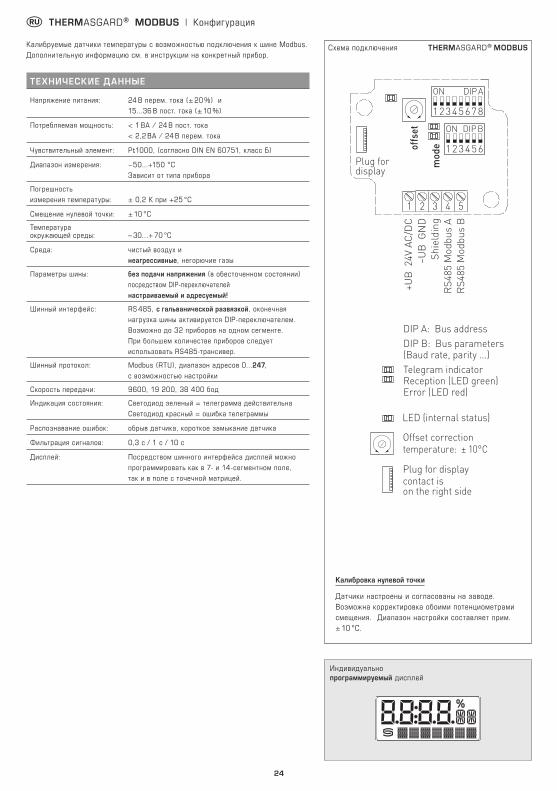
r THERMASGARD® MODBUS | Конфигурация
Калибруемые датчики температуры с возможностью подключения к шине Modbus. Дополнительную информацию см. в инструкции на конкретный прибор.
ТЕХНИЧЕСКИЕ Д АННЫЕ
Напряжение питания: 24 B перем. тока (± 20 %) и 15...36 В пост. тока (± 10 %)
Потребляемая мощность: < 1 ВА ⁄ 24 В пост. тока < 2,2 ВА ⁄ 24 В перем. тока
Чувствительный элемент: Pt1000, (согласно DIN EN 60751, класс Б)
Диапазон измерения: −50...+150 °C Зависит от типа прибора
Погрешность измерения температуры: ± 0,2 K при +25 °C
Смещение нулевой точки: ± 10 °C
Температура окружающей среды: – 30...+ 70 °C
Среда: чистый воздух и неагрессивные, негорючие газы
Параметры шины: без подачи напряжения (в обесточенном состоянии) посредством DIP-переключателей настраиваемый и адресуемый!
Шинный интерфейс: RS 485, с гальванической развязкой, оконечная нагрузка шины активируется DIP-переключателем. Возможно до 32 приборов на одном сегменте. При большем количестве приборов следует использовать RS485-трансивер.
Шинный протокол: Modbus (RTU), диапазон адресов 0...247, с возможностью настройки
Дисплей: Посредством шинного интерфейса дисплей можно программировать как в 7- и 14-сегментном поле, так и в поле с точечной матрицей.
Схема подключения THERMASGARD® MODBUS
1 2 3 4 5
12345678
ON DIP A
123456
ON DIP B
modeoffset
Plug for display
–UB
GN
DSh
ield
ing
RS4
85 M
odbu
s A
RS4
85 M
odbu
s B
+UB
24V
AC
/DC Plug for display
contact ison the right side
DIP A: Bus address DIP B: Bus parameters(Baud rate, parity ...)Telegram indicator Reception (LED green) Error (LED red)
LED (internal status)
Offset correctiontemperature: ± 10°C
Индивидуально программируемый дисплей
Калибровка нулевой точки
Датчики настроены и согласованы на заводе. Возможна корректировка обоими потенциометрами смещения. Диапазон настройки составляет прим. ± 10 °C.
25
r THERMASGARD® MODBUS | Конфигурация
АДРЕС ШИНЫ
Адрес шины (двоичный, настраиваемая значимость от 1 до 247)
MODBUS
DIP-переключатель [A]
DIP 1 DIP 2 DIP 3 DIP 4 DIP 5 DIP 6 DIP 7 DIP 8
1 2 3 4 5 6 7 8
ON DIP A128 64 32 16 8 4 2 1
O N O N OFF OFF OFF OFF OFF O N
Данный пример показывает, что 128 + 64 + 1 = 193 — это адрес шины Modbus.
Адрес прибора в диапазоне от 1 до 247 (двоичный формат) настраивается с помощью DIP-переключателя [A]. Положение переключателей, поз. от 1 до 8 — см. таблицу на обратной стороне!
Адрес 0 зарезервирован для сообщений сети; запрещается определять адреса больше 247; прибор будет игнорировать их. DIP-переключатели имеют двоичное кодирование со следующей значимостью:
DIP 1 = 128 ............ DIP 1 = ON DIP 2 = 64 ............ DIP 2 = ON DIP 3 = 32 ............ DIP 3 = OFF DIP 4 = 16 ............ DIP 4 = OFF DIP 5 = 8 ............ DIP 5 = OFF DIP 6 = 4 ............ DIP 6 = OFF DIP 7 = 2 ............ DIP 7 = OFF DIP 8 = 1 ............ DIP 8 = ON Данный пример показывает, что 128 + 64 + 1 = 193 — это адрес шины Modbus.
ПАРАМЕТРЫ ШИНЫ
Скорость передачи (настраиваемая)
DIP 1
DIP 2
MODBUS
DIP-переключатель [B]
9600 бод O N OFF
1 2 3 4 5 6
ON DIP B19200 бод O N O N
38400 бод OFF O N
зарезервировано OFF OFF
Чётность (настраиваемая)
DIP 3
Контроль чётности (вкл./ выкл.)
DIP 4
8N1-Modus (вкл./выкл.)
DIP 5
Оконечная нагрузка шины (вкл./выкл.)
DIP 6
EVEN (чётные) O N активный
(1 стоповый бит) O N активн. O N активн. O N
ODD (нечётные) OFF неактивный (без чётности)
(2 стоповых бита) OFF неактивный (по умолчанию) OFF неактивная OFF
Скорость передачи данных (в бодах) настраивается с помощью поз. 1 и 2 DIP-переключателя [B]. Можно настроить 9600 бод, 19 200 бод или 38 400 бод — см. таблицу!
Чётность настраивается с помощью поз. 3 DIP-переключателя [B]. Можно настроить EVEN (чётные) или ODD (нечётные) — см. таблицу!
Контроль чётности включается с помощью поз. 4 DIP-переключателя [B]. Можно настроить: контроль чётности — активный (1 стоповый бит) или неактивный (2 стоповых бита), т. е. контроль чётности отсутствует — см. таблицу!
Режим 8N1 включается с помощью поз. 5 DIP-переключателя [B]. При этом функции поз. 3 (чётность) и поз. 4 (контроль чётности) DIP-переключателя [B] становятся неактивными. Можно настроить: режим 8N1 активный или неактивный (по умолчанию) — см. таблицу!
Оконечная нагрузка шины включается с помощью поз. 6 DIP-переключателя [B]. Можно настроить: активная (нагрузочный резистор шины 120 Ом) или неактивная (без оконечной нагрузки шины) – см. таблицу!
В случае приборов с дисплеем при изменении параметров шины и ее адреса соответствующие настройки отображаются на дисплее на протяжении прим. 30 секунд.
ИНДИКАЦИЯ СОСТОЯНИЯ СВЯЗИИндикация состояния связи осуществляется с помощью 2 светодиодных индикаторов. Индикация успешного получения телеграммы производится путем загорания зеленого индикатора независимо от адреса прибора. Индикация телеграмм с ошибками или вызванных исключительных телеграмм Modbus производится путем загорания красного индикатора.
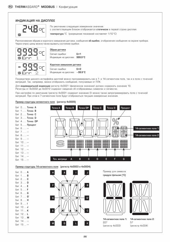
По умолчанию следующее измеренное значение с соответствующим блоком отображается статически в первой строке дисплея:
температура,°C (разрешение показаний составляет 1/10 °C)
Распознавание обрыва и короткого замыкания датчика, сообщение об ошибке, отображение сообщения на экране прибора. Через опрос шины можно также вызвать состояние ошибки.
Обрыв датчика
Сигнал ошибки: Err1 Индикация на дисплее: 999.9 °C
Короткое замыкание датчика
Сигнал ошибки: Err2 Индикация на дисплее: – 99.9 °C
Посредством шинного интерфейса дисплей можно программировать как в 7- и 14-сегментном поле, так и в поле с точечной матрицей. Так, например, можно отображать сообщения, получаемые от ПЛК.
Для индивидуальной индикации регистр 4x0001 (физическое значение) должен содержать значение 10. Регистры от 4х0002 до 4х0012 содержат сведения об отображаемых символах и сегментах.
При настройке по умолчанию (регистр 4x0001 содержит значение 0) можно также запрограммировать поле с точечной матрицей. При этом в 7-сегментном поле будут отображаться текущие измеренные значения.
Пример структуры сегментного поля (регистр 4x0005)
14-сегментное поле 1: 14-сегментное поле 2: 227 57 (регистр 4x003) (регистр 4x004)
27
r THERMASGARD® MODBUS | Конфигурация, телеграммы
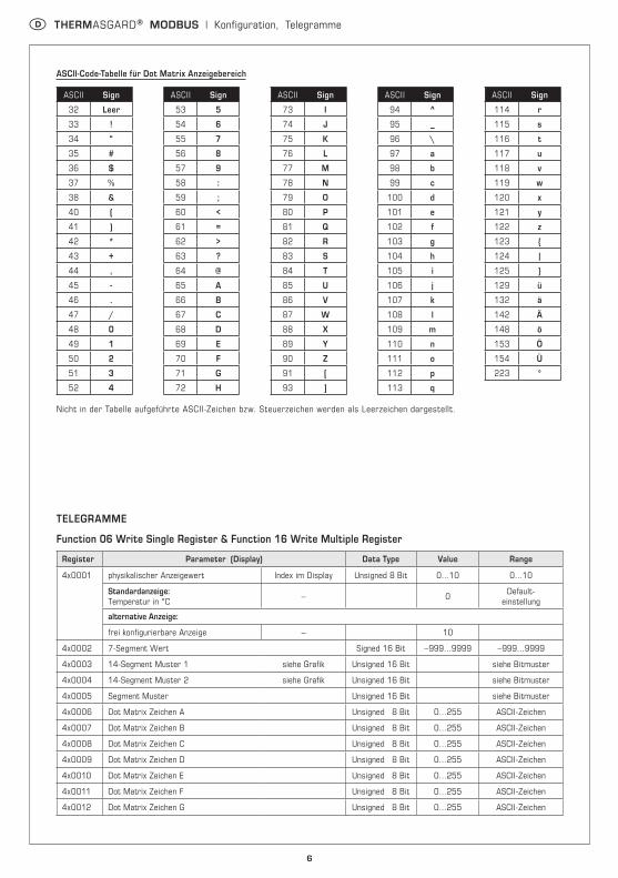
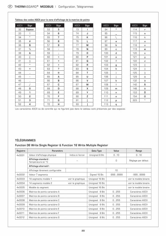
Таблица кодов ASCII для полей с точечной матрицей
ASCII Символ
32 Пробел
33 !
34 “
35 #
36 $
37 %
38 &
40 (
41 )
42 *
43 +
44 ,
45 -
46 .
47 /
48 0
49 1
50 2
51 3
52 4
ASCII Символ
53 5
54 6
55 7
56 8
57 9
58 :
59 ;
60 <
61 =
62 >
63 ?
64 @
65 A
66 B
67 C
68 D
69 E
70 F
71 G
72 H
ASCII Символ
73 I
74 J
75 K
76 L
77 M
78 N
79 O
80 P
81 Q
82 R
83 S
84 T
85 U
86 V
87 W
88 X
89 Y
90 Z
91 [
93 ]
ASCII Символ
94 ^
95 _
96 \
97 a
98 b
99 c
100 d
101 e
102 f
103 g
104 h
105 i
106 j
107 k
108 l
109 m
110 n
111 o
112 p
113 q
ASCII Символ
114 r
115 s
116 t
117 u
118 v
119 w
120 x
121 y
122 z
123 {
124 |
125 }
129 ü
132 ä
142 Ä
148 ö
153 Ö
154 Ü
223 °
Неуказанные в таблице символы ASCII или управляющие символы отображаются в виде пробела.
ТЕЛЕГРАММЫ
Функция 06 — Запись значения в один регистр хранения (Write Single Register) и функция 16 — Запись значений в несколько регистров хранения (Write Multiple Register)
Регистр Параметр Тип данных Значение Диапазон
4x0001 Физическое значение Индекс на дисплее Без знака 8 бит 0...10 0...10
Стандартная индикация: Температура, °C – 0 Настройка по умолчанию
Альтернативная индикация:
Настраиваемая индикация 10
4x0002 7-сегментное значение Со знаком 16 бит −999...9999 −999...9999
4x0003 Пример 14-сегментного поля 1 см. рисунок Без знака 16 бит см. битовую комбинацию
4x0004 Пример 14-сегментного поля 2 см. рисунок Без знака 16 бит см. битовую комбинацию
4x0005 Пример сегментного поля Без знака 16 бит см. битовую комбинацию
4x0006 Точечная матрица, символ А Без знака 8 бит 0...255 Символ ASCII
4x0007 Точечная матрица, символ В Без знака 8 бит 0...255 Символ ASCII
4x0008 Точечная матрица, символ С Без знака 8 бит 0...255 Символ ASCII
4x0009 Точечная матрица, символ D Без знака 8 бит 0...255 Символ ASCII
4x0010 Точечная матрица, символ Е Без знака 8 бит 0...255 Символ ASCII
4x0011 Точечная матрица, символ F Без знака 8 бит 0...255 Символ ASCII
4x0012 Точечная матрица, символ G Без знака 8 бит 0...255 Символ ASCII
28
r THERMASGARD® MODBUS | Телеграммы
Функция 04 — Чтение регистров ввода (Read Input Register)
Регистр Параметр Тип данных Значение Диапазон
3x0001 Температура Без фильтрации Со знаком 16 бит – 500...+ 1500 – 999...+ 9999
– 50.0 ... +150.0 °C Выбег
3x0002 Температура Фильтрация 1 с Со знаком 16 бит – 500...+ 1500 – 999...+ 9999
– 50.0 ... +150.0 °C Выбег
3x0003 Температура Фильтрация 10 с Со знаком 16 бит – 500...+ 1500 – 999...+ 9999
– 50.0 ... +150.0 °C Выбег
Функция 02 — Чтение значений из нескольких дискретных входов (Read Discrete Input)
Регистр Параметр Тип данных Значение Диапазон
0x0001 Ошибка датчика — обрыв Бит 0 0 / 1 ON - OFF
0x0002 Ошибка датчика — короткое замыкание Бит 1 0 / 1 ON - OFF
Примечание: адреса от 1x0003 до 1x0008 читаются со значением «0».
Функция 08 — Диагностика (Diagnostics) Поддерживаются следующие коды подфункции
Код подфункции
Параметр Тип данных Ответ
00 Эхо отправленных данных (Loopback) Данные эхо
01 Перезапуск Modbus (Reset Listen Only Mode) Телеграмма эхо
04 Активация Listen Only Mode Без ответа
10 Сброс счетчиков Телеграмма эхо
11 Счетчик телеграмм шины Без знака 16 бит Все действительные телеграммы шины
12
Счетчик ошибок связи (четность, циклическая проверка четность с избыточностью (CRC), ошибка фрейма и т. д.)
Без знака 16 бит Телеграммы шины с ошибками
13 Счетчик исключительных сообщений Без знака 16 бит Счетчик ошибок
14 Счетчик телеграмм ведомого устройства Без знака 16 бит Телеграммы ведомого устройства
15 Счетчик телеграмм без ответа Без знака 16 бит Сообщения сети (адрес 0)
Функция 17 — Чтение информации об устройстве (Report Slave ID) Структура телеграммы ответа
Бит № Параметр Тип данных Ответ
00 Количество байт Без знака 8 бит 6
01 Идентификатор ведомого устройства (тип устройства) Без знака 8 бит 2 = THERMASGARD® MODBUS
02 Идентификатор ведомого устройства (класс устройства) Без знака 8 бит 10 = THERMASGARD® / THERMASREG®
03 Состояние Без знака 8 бит 255 = RUN, 0 = STOP
04 Номер версии (выпуск) Без знака 8 бит 1...9
05 Номер версии (версия) Без знака 8 бит 1…99
06 Номер версии (индекс) Без знака 8 бит 1
29
Общая структура шины
Магистральная конфигурация с нагрузочными резисторами и резисторами в цепи смещения
Нагрузочные резисторы должны устанавливаться только на концах шины. В сетях без повторителей разрешается использовать не больше двух оконечных нагрузок шины. С помощью DIP-переключателя 6 можно активировать оконечную нагрузку шины на приборе. Резисторы в цепи смещения для определения уровня шины в состоянии покоя обычно активируются на главном устройстве Modbus/повторителе.
Максимальное количество абонентов на один сегмент Modbus составляет 32 прибора. В случае большего количества абонентов следует разделить шину с помощью повторителей на несколько сегментов. Адреса абонентов можно настраивать от 1 до 247.
Для линии шины следует использовать кабель с парной скруткой/электропитанием и медным экраном. Емкость линии на единицу длины должна составлять при этом меньше 100 пФ/м (напр., линия Profibus).
r THERMASGARD® MODBUS | Установка
Slave n
MODBUSRTU-Master
RS-485
Оконечная нагрузка шины
Оконечная нагрузка шины
Активноеответвление
Пассивноеответвление
Тупиковая линия (ответвитель-ный кабель)
Магистральная линия (магистральный кабель)
Тупиковая линия:короче 20 м
Многократное ответвление n:короче 40 м/n
Общая структура шины
Slave 1 Slave 2
LA LA
Магистральная конфигурация с нагрузочными резисторами и резисторами в цепи смещения
A (D1) D+
5 B
Общее заземление
(GND)
B (D0) D–
Оконечная нагрузка шины
Оконечная нагрузка шины
Стягивающий резистор / резистор в цепи смещения
Подтягивающий резистор / резистор в цепи смещения
MODBUSRTU-Master
Slave 1 Slave 2
30
r Указания к продуктам
В качестве Общих Коммерческих Условий имеют силу исключительно наши Условия, а также действительные «Общие условия поставки продукции и услуг для электрической промышленности» (ZVEI) включая дополнительную статью «Расширенное сохранение прав собственности».
Помимо этого, следует учитывать следующие положения:– Подключение прибора должно осуществляться исключительно к безопасно малому напряжению и в обесточенном состоянии.
Во избежание повреждений и отказов (например, вследствие наводок) следует использовать экранированную проводку, избегать параллельной прокладки токоведущих линий и учитывать предписания по электромагнитной совместимости.
– Данный прибор следует применять только по прямому назначению, учитывая при этом соответствующие предписания VDE (союза немецких электротехников), требования, действующие в Вашей стране, инструкции органов технического надзора и местных органов энергоснабжения. Надлежит придерживаться требований строительных норм и правил, а также техники безопасности и избегать угроз безопасности любого рода.
– Мы не несем ответственности за ущерб и повреждения, возникающие вследствие неправильного применения наших устройств.– Ущерб, возникший вследствие неправильной работы прибора, не подлежит устранению по гарантии.– Установка приборов должна осуществляться только квалифицированным персоналом.– Действительны исключительно технические данные и условия подключения, приведенные в поставляемых с приборами руководствах
по монтажу и эксплуатации. Отклонения от представленных в каталоге характеристик дополнительно не указываются, несмотря на их возможность в силу технического прогресса и постоянного совершенствования нашей продукции.
– В случае модификации приборов потребителем гарантийные обязательства теряют силу.– Не разрешается использование прибора в непосредственной близости от источников тепла (например, радиаторов отопления)
или создаваемых ими тепловых потоков; следует в обязательном порядке избегать попадания прямых солнечных лучей или теплового излучения от аналогичных источников (мощные осветительные приборы, галогенные излучатели).
– Эксплуатация вблизи оборудования, не соответствующего нормам электромагнитной совместимости (ЭМС), может влиять на работу приборов.– Недопустимо использование данного прибора в качестве устройства контроля ⁄ наблюдения, служащего для защиты людей от травм и угрозы
для здоровья ⁄ жизни, а также в качестве аварийного выключателя устройств и машин или для аналогичных задач обеспечения безопасности.– Размеры корпусов и корпусных принадлежностей могут в определённых пределах отличаться от указанных в данном руководстве.– Изменение документации не допускается.– В случае рекламаций принимаются исключительно цельные приборы в оригинальной упаковке.
Перед установкой и вводом в эксплуатацию следует прочитать данное руководство; должны быть учтены все приведенные в нем указания!
r Монтаж и подключение
Приборы следует устанавливать в обесточенном состоянии. Подключение должно осуществляться исключительно к безопасно малому напряжению. Повреждения приборов вследствие несоблюдения упомянутых требований не подлежат устранению по гарантии; ответственность производителя исключается. Установка приборов должна осущест-вляться только авторизованным персоналом. Действительны исключительно технические данные и условия подключения, приведенные на поставляемых с приборами этикетках ⁄ табличках и в руководствах по монтажу и эксплуатации. Отклонения от представ-ленных в каталоге характеристик дополнительно не указываются, несмотря на их возможность в силу технического прогресса и посто-янного совершенствования нашей продукции. В случае модификации приборов потребителем гарантийные обязательства теряют силу. Эксплуатация вблизи оборудования, не соответствующего нормам электромагнитной совместимости (EMV), может влиять на работу приборов. Недопустимо использование данного прибора в качестве устройства контроля ⁄ наблюдения, служащего для защиты людей от травм и угрозы для здоровья ⁄ жизни, а также в качестве аварийного выключателя устройств и машин или для аналогичных задач обеспе-чения безопасности.Размеры корпусов и корпусных принадлежностей могут в определённых пределах отличаться от указанных в данном руководстве.Изменение документации не допускается.В случае рекламаций принимаются исключительно цельные приборы в оригинальной упаковке.
Указания к механическому монтажу:Монтаж должен осуществляться с учетом соответствующих, действительных для места измерения предписаний и стандартов (напр., предписаний для сварочных работ). В особенности следует принимать во внимание:
– указания VDE ⁄ VDI (союз немецких электротехников ⁄ союз немецких инженеров) к техническим измерениям температуры, директивы по устройствам измерения температуры
– директивы по электромагнитной совместимости (их следует придерживаться)
– непременно следует избегать параллельной прокладки токоведущих линий
– рекомендуется применять экранированную проводку; экран следует при этом с одной стороны монтировать к DDC ⁄ PLC.
Монтаж следует осуществлять с учетом соответствия прилагаемых технических параметров термометра реальным условиям эксплуатации, в особенности:
– диапазона измерения– максимально допустимого давления и скорости потока– установочной длины, размера трубки– допустимых колебаний, вибраций, ударов (д.б. < 0,5 g).
Внимание! В обязательном порядке следует учитывать предельные допустимые механические и термические нагрузки для защитных трубок согл. DIN 43763 либо специальных стандартов S+S !
Указания к монтажу встраиваемых датчиков:Материал защитной трубки следует выбирать таким образом, чтобы он по возможности соответствовал материалу соединительной трубки или стенки резервуара, в которую встраивается термометр!
Максимальная температура Tmax и максимальное давление pmax : для латунных втулок TH-ms Tmax = +150 °C, pmax = 10 бар; для втулок из высококачественной стали TH-VA (стандартно) Tmax = + 400 °C, pmax = 40 бар.
Присоединительная резьба:При монтаже следует обращать внимание на правильную укладку уплотнения или уплотнительного материала! Нормативные значения допустимого момента затяжки для присоединительной резьбы:
M 18 x 1,5; M 20 x 1,5; G ½ " : 50 Нм M 27 x 2,0; G ¾ " : 100 Нм
Фланцевое соединение:Винты при фланцевом закреплении следует затягивать равномерно. Боковой упорный винт должен обеспечивать надежную фиксацию, в противном случае возможно проскальзывание стержня датчика.
Приварные втулки:
Следует учитывать специальные правила проведения сварочных работ. Недопустимо возникновение неровностей или аналогичных дефектов в зоне сварного шва, которые оказывают влияние на «cleaning in place»-пригодность установки.Для трубопроводов высокого давления необходимы устройства понижения давления и оборудование для контроля.
31
THERMASGARD® MODBUS
D G F r
Irrtümer und technische Änderungen vorbehalten. Errors and technical changes excepted. Sous réserve d’erreurs et de modifications techniques. Возможны ошибки и технические изменения.
Nachdruck, auch auszugsweise, nur mit Genehmigung von S+S Regeltechnik GmbH gestattet. Reprints, in part or in total, are only permitted with the approval of S+S Regeltechnik GmbH. La reproduction des textes même partielle est uniquement autorisée après accord de la société S+S Regeltechnik GmbH. Перепечатка, в том числе в сокращенном виде, разрешается лишь с согласия S+S Regeltechnik GmbH.
32
D G F rBusadresse, binärcodiert Bus address, binary coded Adresse du bus, code binaire Адресс шины, двоичный