68
Festo Didactic 8040796 de/en 01/2015 R0.9 8039313/8038848 Station Roboter mit MPS ® Modulen Robot station with MPS ® modules MPS ® Handbuch Manual
Festo Didactic
8040796 de/en
01/2015 R0.9
8039313/8038848
Station Roboter mit MPS® Modulen
Robot station with MPS® modules
MPS®
Handbuch
Manual
Bestell-Nr./Order no.: 8040796
Stand/Revision level: 01/2015
Autoren/Authors: Frank Ebel, Mustafa Ersoy, Dirk Pensky
Layout: 03/2015, Frank Ebel
© Festo Didactic GmbH & Co. KG, 73770 Denkendorf, Germany, 2015
All rights reserved.
Internet: www.festo-didactic.com
E-mail: [email protected]
Weitergabe sowie Vervielfältigung dieses Dokuments, Verwertung und Mitteilung seines Inhalts verboten,
soweit nicht ausdrücklich gestattet. Zuwiderhandlungen verpflichten zu Schadenersatz. Alle Rechte
vorbehalten, insbesondere das Recht, Patent-, Gebrauchsmuster- oder Geschmacksmusteranmeldungen
durchzuführen.
Reproduction, distribution and utilisation of this document, as well as the communication of its contents to
others without explicit authorisation, is prohibited. Offenders will be held liable for damages. All rights
reserved, in particular the right to file patent, utility model and registered design applications.
Deutsch _______________________________________________________________________________ 3
English _____________________________________________________________________________ 35
© Festo Didactic 8040796 3
Inhalt
1 Allgemeine Voraussetzungen zum Betreiben der Geräte ___________________________________ 5
2 Piktogramme ______________________________________________________________________ 5
3 Bestimmungsgemäße Verwendung ____________________________________________________ 6
4 Für Ihre Sicherheit __________________________________________________________________ 6
4.1 Wichtige Hinweise __________________________________________________________________ 6
4.2 Verpflichtung des Betreibers __________________________________________________________ 7
4.3 Verpflichtung der Auszubildenden _____________________________________________________ 7
4.4 Gefahren im Umgang mit dem Modularen Produktions-System ______________________________ 7
4.5 Sicher arbeiten _____________________________________________________________________ 7
5 Technische Daten _________________________________________________________________ 11
5.1 Kontaktbelegung Station (X0 am Robotercontroller) _____________________________________ 12
5.2 Kontaktbelegungstabelle (Handsensorstecker CON1H) ___________________________________ 13
5.3 Kontaktbelegungstabelle (Magnetventilanschluss) ______________________________________ 14
6 Transport/Auspacken/Lieferumfang _________________________________________________ 15
6.1 Transport ________________________________________________________________________ 15
6.2 Auspacken _______________________________________________________________________ 15
6.3 Lieferumfang _____________________________________________________________________ 15
7 Aufbau __________________________________________________________________________ 16
7.1 Die Station Roboter mit MPS® Modulen _______________________________________________ 16
7.2 Das Modul Roboterhandling ________________________________________________________ 17
7.3 Das Modul Robotermontage ________________________________________________________ 18
8 Funktion ________________________________________________________________________ 19
9 Ablaufbeschreibung _______________________________________________________________ 20
10 Inbetriebnahme __________________________________________________________________ 22
10.1 Arbeitsplatz ______________________________________________________________________ 22
10.2 Kabelanschlüsse __________________________________________________________________ 23
10.3 Pneumatischer Anschluss __________________________________________________________ 26
10.4 Spannungsversorgung _____________________________________________________________ 27
10.5 Inbetriebnahme des Robotersystems _________________________________________________ 27

Inhalt
4 © Festo Didactic 8040796
10.6 Roboter Programm laden ___________________________________________________________ 28
10.7 Positionen teachen ________________________________________________________________ 28
10.7.1 Jog-Operation Modus ______________________________________________________________ 29
10.7.2 Hand-Operation Modus ____________________________________________________________ 30
10.7.3 Achsen ausrichten ________________________________________________________________ 30
10.7.4 Positionen teachen ________________________________________________________________ 31
10.8 Ablauf starten ____________________________________________________________________ 33
11 Wartung und Pflege _______________________________________________________________ 34
11.1 Jährlicher Austausch der Pufferbatterien ______________________________________________ 34
12 Weitere Informationen und Aktualisierungen __________________________________________ 34
Station Roboter mit MPS® Modulen
© Festo Didactic 8040796 5
1 Allgemeine Voraussetzungen zum Betreiben der Geräte
Der Labor- oder Unterrichtsraum muss mit den folgenden Einrichtungen ausgestattet sein:
Es muss eine NOT-AUS-Einrichtung vorhanden sein.
– Innerhalb und mindestens ein NOT-AUS außerhalb des Labor- oder Unterrichtsraums.
Der Labor- oder Unterrichtsraum ist gegen unbefugtes Einschalten der Betriebsspannung bzw. der
Druckluftversorgung zu sichern.
– z. B. Schlüsselschalter
– z. B. abschließbare Einschaltventile
Der Labor- oder Unterrichtsraum muss durch Fehlerstromschutzeinrichtungen (RCD) geschützt werden.
– RCD-Schutzschalter mit Differenzstrom ≤ 30 mA, Typ B.
Der Labor- oder Unterrichtsraum muss durch Überstromschutzeinrichtungen geschützt sein.
– Sicherungen oder Leitungsschutzschalter
Der Labor- oder Unterrichtsraum muss durch einen Arbeitsverantwortlichen überwacht werden.
– Ein Arbeitsverantwortlicher ist eine Elektrofachkraft oder eine elektrotechnisch unterwiesene
Person mit Kenntnis von Sicherheitsanforderungen und Sicherheitsvorschriften mit
aktenkundiger Unterweisung.
Es dürfen keine Geräte mit Schäden oder Mängeln verwendet werden.
– Schadhafte Geräte sind zu sperren und aus dem Labor- oder Unterrichtsraum zu entnehmen.
Allgemeine Anforderungen bezüglich des sicheren Betriebs der Geräte:
Verlegen Sie Leitungen nicht über heiße Oberflächen.
– Heiße Oberflächen sind mit einem Warnsymbol entsprechend gekennzeichnet.
Die zulässigen Strombelastungen von Leitungen und Geräten dürfen nicht überschritten werden.
– Vergleichen Sie stets die Strom-Werte von Gerät, Leitung und Sicherung.
– Benutzen Sie bei Nichtübereinstimmung eine separate vorgeschaltete Sicherung als
entsprechenden Überstromschutz.
Geräte mit Erdungsanschluss sind stets zu erden.
– Sofern ein Erdanschluss (grün-gelbe Laborbuchse) vorhanden ist, so muss der Anschluss an
Schutzerde stets erfolgen. Die Schutzerde muss stets als erstes (vor der Spannung) kontaktiert
werden und darf nur als letztes (nach Trennung der Spannung) getrennt werden.
Wenn in den Technischen Daten nicht anders angegeben, besitzt das Gerät keine integrierte Sicherung.
2 Piktogramme
Dieses Dokument und die beschriebene Hardware enthalten Hinweise auf mögliche Gefahren, die bei
unsachgemäßem Einsatz des Systems auftreten können. Folgende Piktogramme werden verwendet:
Warnung
… bedeutet, dass bei Missachten schwerer Personen- oder Sachschaden entstehen
kann.
Station Roboter mit MPS® Modulen
6 © Festo Didactic 8040796
3 Bestimmungsgemäße Verwendung
Die Stationen des Modularen Produktions-Systems sind nur zu benutzen:
für die bestimmungsgemäße Verwendung im Lehr- und Ausbildungsbetrieb
in sicherheitstechnisch einwandfreiem Zustand
Die Stationen sind nach dem heutigen Stand der Technik und den anerkannten sicherheitstechnischen
Regeln gebaut. Dennoch können bei unsachgemäßer Verwendung Gefahren für Leib und Leben des
Benutzers oder Dritter und Beeinträchtigungen der Komponenten entstehen.
Das Lernsystem von Festo Didactic ist ausschließlich für die Aus- und Weiterbildung im Bereich
Automatisierung und Technik entwickelt und hergestellt. Das Ausbildungsunternehmen und/oder die
Ausbildenden hat/haben dafür Sorge zu tragen, dass die Auszubildenden die Sicherheitsvorkehrungen, die
in diesem Arbeitsbuch beschrieben sind, beachten.
Festo Didactic schließt hiermit jegliche Haftung für Schäden des Auszubildenden, des
Ausbildungsunternehmens und/oder sonstiger Dritter aus, die bei Gebrauch/Einsatz dieses Gerätes
außerhalb einer reinen Ausbildungssituation auftreten; es sei denn Festo Didactic hat solche Schäden
vorsätzlich oder grob fahrlässig verursacht.
4 Für Ihre Sicherheit
4.1 Wichtige Hinweise
Grundvoraussetzung für den sicherheitsgerechten Umgang und den störungsfreien Betrieb des MPS ist die
Kenntnis der grundlegenden Sicherheitshinweise und der Sicherheitsvorschriften. Dieses Handbuch enthält
die wichtigsten Hinweise, um das MPS sicherheitsgerecht zu betreiben.
Insbesondere die Sicherheitshinweise sind von allen Personen zu beachten, die am MPS arbeiten.
Darüber hinaus sind die für den Einsatzort geltenden Regeln und Vorschriften zur Unfallverhütung zu
beachten.
Station Roboter mit MPS® Modulen
© Festo Didactic 8040796 7
4.2 Verpflichtung des Betreibers
Der Betreiber verpflichtet sich, nur Personen am MPS arbeiten zu lassen, die:
mit den grundlegenden Vorschriften über Arbeitssicherheit und Unfallverhütung vertraut und in die
Handhabung des MPS eingewiesen sind,
das Sicherheitskapitel und die Warnhinweise in diesem Handbuch gelesen und verstanden haben.
Das sicherheitsbewusste Arbeiten des Personals soll in regelmäßigen Abständen überprüft werden.
4.3 Verpflichtung der Auszubildenden
Alle Personen, die mit Arbeiten am MPS beauftragt sind, verpflichten sich, vor Arbeitsbeginn:
das Sicherheitskapitel und die Warnhinweise in diesem Handbuch zu lesen,
die grundlegenden Vorschriften über Arbeitssicherheit und Unfallverhütung zu beachten.
4.4 Gefahren im Umgang mit dem Modularen Produktions-System
Das MPS ist nach dem Stand der Technik und den anerkannten sicherheitstechnischen Regeln gebaut.
Dennoch können bei ihrer Verwendung Gefahren für Leib und Leben des Benutzers oder Dritter bzw.
Beeinträchtigungen an der Maschine oder an anderen Sachwerten entstehen.
Das MPS ist nur zu benutzen:
für die bestimmungsgemäße Verwendung und
in sicherheitstechnisch einwandfreiem Zustand.
Störungen, die die Sicherheit beeinträchtigen können, sind umgehend zu beseitigen!
4.5 Sicher arbeiten
Allgemein
Die Auszubildenden dürfen nur unter Aufsicht einer Ausbilderin/eines Ausbilders an den Schaltungen
arbeiten.
Betreiben Sie elektrische Geräte (z. B. Netzgeräte, Verdichter, Hydraulikaggregate) nur in
Ausbildungsräumen, die mit einer Fehlerstromschutzeinrichtung (RCD) ausgestattet sind.
Beachten Sie die Angaben der Datenblätter zu den einzelnen Komponenten, insbesondere auch alle
Hinweise zur Sicherheit!
Station Roboter mit MPS® Modulen
8 © Festo Didactic 8040796
Störungen, die die Sicherheit beeinträchtigen können, dürfen beim Schulungsbetrieb nicht erzeugt
werden und sind umgehend zu beseitigen.
Tragen Sie Ihre persönliche Schutzausrüstung (Schutzbrille, Sicherheitsschuhe), wenn Sie an den
Schaltungen arbeiten.
Mechanik
Greifen Sie nur bei Stillstand in den Aufbau.
Montieren Sie alle Komponenten fest auf die Profilplatte.
Grenztaster dürfen nicht frontal betätigt werden.
Verletzungsgefahr bei der Fehlersuche!
Benutzen Sie zur Betätigung der Grenztaster ein Werkzeug, z. B. einen Schraubendreher.
Stellen Sie alle Komponenten so auf, dass das Betätigen von Schaltern und Trenneinrichtungen nicht
erschwert wird.
Beachten Sie Angaben zur Platzierung der Komponenten.
Elektrik
Verwenden Sie nur Schutzkleinspannungen, maximal 24 V DC.
Herstellen bzw. Abbauen von elektrischen Anschlüssen nur in spannungslosem Zustand!
Verwenden Sie für die elektrischen Anschlüsse nur Verbindungsleitungen mit Sicherheitssteckern.
Ziehen Sie beim Abbauen der Verbindungsleitungen nur an den Sicherheitssteckern, nicht an den
Leitungen.
Industrieroboter
Beachten Sie die Angaben des Sicherheitstechnischen Handbuchs für MELFA Industrieroboter von
Mitsubishi.
Transportieren des Roboters
– Soll der Roboter nach einer erfolgten Installation erneut transportiert werden, so ist darauf zu
achten, dass die Bremsen des Roboterarms gelöst werden und der Arm wieder in die
Transportposition gebracht wird. Der Roboter darf niemals mit ausgefahrenem Arm getragen oder
transportiert werden.
– Vor einem erneuten Transport müssen die Transportsicherungen montiert werden.
Bringen Sie um den Roboter herum eine Sicherheitsbarriere oder Einfriedung an, damit bei
unbedachter Annäherung an den Roboter potenzielle Gefahren ausgeschaltet werden.
Bringen Sie eine Sicherheitsverriegelung an, die das Öffnen der Tür verhindert, wenn ein Bediener
versucht, die Barriere (innerhalb des Sicherheitsbereichs) zu passieren, während der Roboter in Betrieb
ist, oder durch die beim Öffnen der Tür die Servo-Stromversorgung des Roboters ausgeschaltet und
Peripheriegeräte automatisch angehalten werden (die Servo-Stromversorgung ausgeschaltet wird).
Schließen Sie die Leitung dieses Sicherheitsverriegelungssignals direkt an den Roboter und die
Peripheriegeräte an und nicht an ein Sekundärgerät (z.B. SPS). Schließen Sie die Leitung bei den
Robotern von MITSUBISHI an die Eingangsklemme des NOT-HALT-Schalters oder des Türschalters an.
Installieren Sie das Robotersystem so, dass sich das Steuergerät außerhalb des Sicherheitsbereichs
befindet.
Station Roboter mit MPS® Modulen
© Festo Didactic 8040796 9
Bringen Sie an einer leicht zugänglichen Stelle in Roboternähe einen manuellen NOT-HALT Schalter an
und verbinden Sie diesen mit der Notausschaltungs-Eingangsklemme des Steuergerätes.
Konfigurieren Sie das System so, dass der Betriebsstatus des Roboters (d. h.
Ausführungsprogrammbetrieb, Stoppstatus, Servo-Ein-Status, Fehlerstatus usw.) anhand von
Sichtanzeigen o. Ä. problemlos extern überprüft werden kann.
Alle Fehler sollten zur Sicherheit des Bedienungspersonals in unmittelbarer Nähe des Roboters durch
Hör- und Sichtsignale angezeigt werden.
Achten Sie zur Vermeidung von Stromschlag und elektrostatischer Entladung, zur Verbesserung des
Störwiderstands und zur Verhinderung unnötiger elektromagnetischer Abstrahlung auf eine
ordnungsgemäße Erdung von Roboter und Steuergerät.
Falls es erforderlich wird, dass ein Bediener zu Schulungs- und Justierzwecken o. Ä. den Bereich hinter
der Barriere bei eingeschalteter Servoversorgung betritt, so muss er einen Schutzhelm tragen. Bei der
Teach-In-Programmierung muss der Servo-Ein-Betrieb so über den Tormannschalter durchgeführt
werden, dass die Servostromversorgung jederzeit ausgeschaltet werden kann und dass genügend Platz
für den Körper des Bedieners besteht, um potenzielle Gefahren zu vermeiden.
Bestimmen Sie bei der Teamarbeit einen Verantwortlichen und stellen Sie sicher, dass Handzeichen und
Befehle eingehend bekannt und der Sicherheit dienlich sind.
Der Anschluss der Kabel darf nur bei ausgeschalteter Spannungsversorgung erfolgen. Es besteht
Stromschlaggefahr.
Berühren Sie während des Betriebes kein bewegliches Teil des Roboters. Schalten Sie den Roboter vor
jeder Arbeit in Reichweite des Roboters aus.
Bewahren Sie eine nicht angeschlossene Teaching-Box wegen der Nichtwirksamkeit der integrierten
NOT-HALT Einrichtung nicht in der Nähe des Roboters auf.
Pneumatik
Überschreiten Sie nicht den zulässigen Druck von 600 kPa (6 bar).
Schalten Sie die Druckluft erst ein, wenn Sie alle Schlauchverbindungen hergestellt und gesichert
haben.
Entkuppeln Sie keine Schläuche unter Druck.
Verletzungsgefahr beim Einschalten von Druckluft!
Zylinder können selbsttätig aus- und einfahren.
Unfallgefahr durch ausfahrende Zylinder!
– Platzieren Sie pneumatische Zylinder immer so, dass der Arbeitsraum der Kolbenstange über den
gesamten Hubbereich frei ist.
– Stellen Sie sicher, dass die Kolbenstange gegen starre Komponenten des Aufbaus fahren kann.
Unfallgefahr durch abspringende Schläuche!
– Verwenden Sie kürzest mögliche Schlauchverbindungen.
– Beim Abspringen von Schläuchen:
Schalten Sie die Druckluftzufuhr sofort ab.
Station Roboter mit MPS® Modulen
10 © Festo Didactic 8040796
Pneumatischer Schaltungsaufbau
Verbinden Sie die Geräte mit dem Kunststoffschlauch mit 4 mm oder 6 mm Außendurchmesser. Stecken
Sie dabei den Schlauch bis zum Anschlag in die Steckverbindung.
Schalten Sie vor dem Schaltungsabbau die Druckluftversorgung ab.
Pneumatischer Schaltungsabbau
Drücken Sie den blauen Lösungsring nieder, der Schlauch kann abgezogen werden.
Station Roboter mit MPS® Modulen
© Festo Didactic 8040796 11
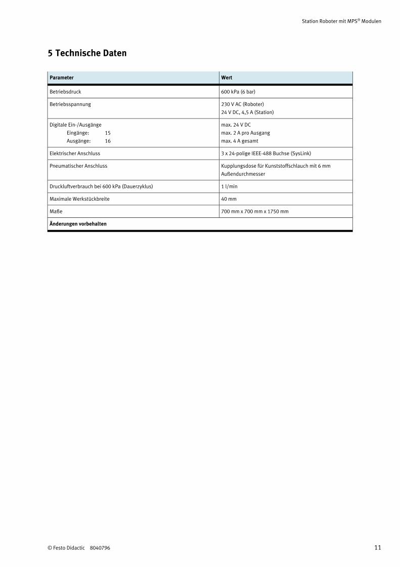
5 Technische Daten
Parameter Wert
Betriebsdruck 600 kPa (6 bar)
Betriebsspannung 230 V AC (Roboter)
24 V DC, 4,5 A (Station)
Digitale Ein-/Ausgänge
Eingänge: 15
Ausgänge: 16
max. 24 V DC
max. 2 A pro Ausgang
max. 4 A gesamt
Elektrischer Anschluss 3 x 24-polige IEEE-488 Buchse (SysLink)
Pneumatischer Anschluss Kupplungsdose für Kunststoffschlauch mit 6 mm
Außendurchmesser
Druckluftverbrauch bei 600 kPa (Dauerzyklus) 1 l/min
Maximale Werkstückbreite 40 mm
Maße 700 mm x 700 mm x 1750 mm
Änderungen vorbehalten
Station Roboter mit MPS® Modulen
12 © Festo Didactic 8040796
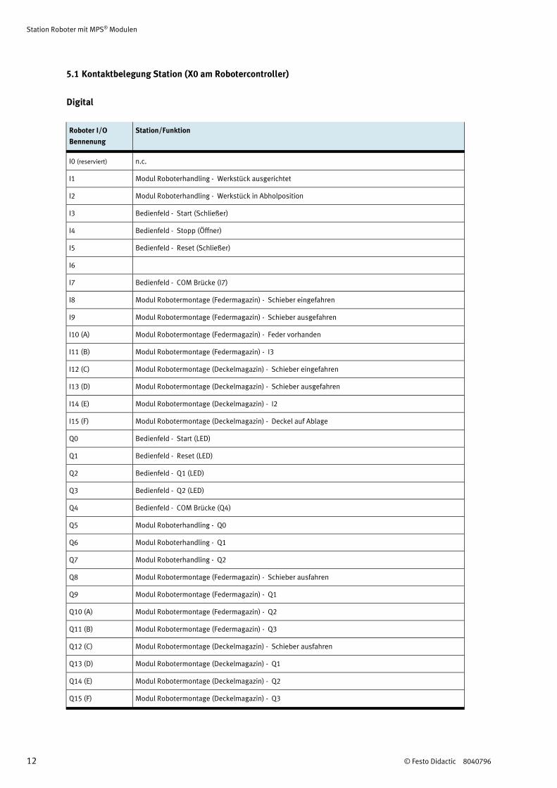
5.1 Kontaktbelegung Station (X0 am Robotercontroller)
Digital
Roboter I/O
Bennenung
Station/Funktion
I0 (reserviert) n.c.
I1 Modul Roboterhandling - Werkstück ausgerichtet
I2 Modul Roboterhandling - Werkstück in Abholposition
I3 Bedienfeld - Start (Schließer)
I4 Bedienfeld - Stopp (Öffner)
I5 Bedienfeld - Reset (Schließer)
I6
I7 Bedienfeld - COM Brücke (I7)
I8 Modul Robotermontage (Federmagazin) - Schieber eingefahren
I9 Modul Robotermontage (Federmagazin) - Schieber ausgefahren
I10 (A) Modul Robotermontage (Federmagazin) - Feder vorhanden
I11 (B) Modul Robotermontage (Federmagazin) - I3
I12 (C) Modul Robotermontage (Deckelmagazin) - Schieber eingefahren
I13 (D) Modul Robotermontage (Deckelmagazin) - Schieber ausgefahren
I14 (E) Modul Robotermontage (Deckelmagazin) - I2
I15 (F) Modul Robotermontage (Deckelmagazin) - Deckel auf Ablage
Q0 Bedienfeld - Start (LED)
Q1 Bedienfeld - Reset (LED)
Q2 Bedienfeld - Q1 (LED)
Q3 Bedienfeld - Q2 (LED)
Q4 Bedienfeld - COM Brücke (Q4)
Q5 Modul Roboterhandling - Q0
Q6 Modul Roboterhandling - Q1
Q7 Modul Roboterhandling - Q2
Q8 Modul Robotermontage (Federmagazin) - Schieber ausfahren
Q9 Modul Robotermontage (Federmagazin) - Q1
Q10 (A) Modul Robotermontage (Federmagazin) - Q2
Q11 (B) Modul Robotermontage (Federmagazin) - Q3
Q12 (C) Modul Robotermontage (Deckelmagazin) - Schieber ausfahren
Q13 (D) Modul Robotermontage (Deckelmagazin) - Q1
Q14 (E) Modul Robotermontage (Deckelmagazin) - Q2
Q15 (F) Modul Robotermontage (Deckelmagazin) - Q3
Station Roboter mit MPS® Modulen
© Festo Didactic 8040796 13
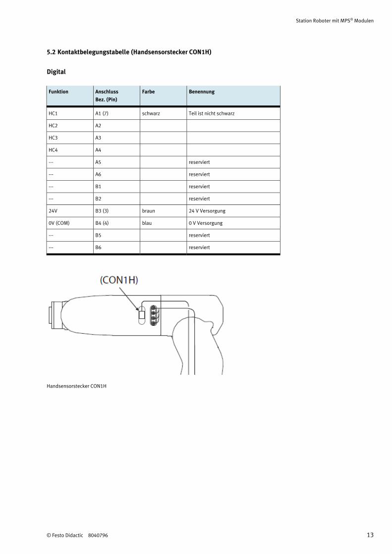
5.2 Kontaktbelegungstabelle (Handsensorstecker CON1H)
Digital
Funktion Anschluss
Bez. (Pin)
Farbe Benennung
HC1 A1 (7) schwarz Teil ist nicht schwarz
HC2 A2
HC3 A3
HC4 A4
--- A5 reserviert
--- A6 reserviert
--- B1 reserviert
--- B2 reserviert
24V B3 (3) braun 24 V Versorgung
0V (COM) B4 (4) blau 0 V Versorgung
--- B5 reserviert
--- B6 reserviert
Handsensorstecker CON1H
Station Roboter mit MPS® Modulen
14 © Festo Didactic 8040796
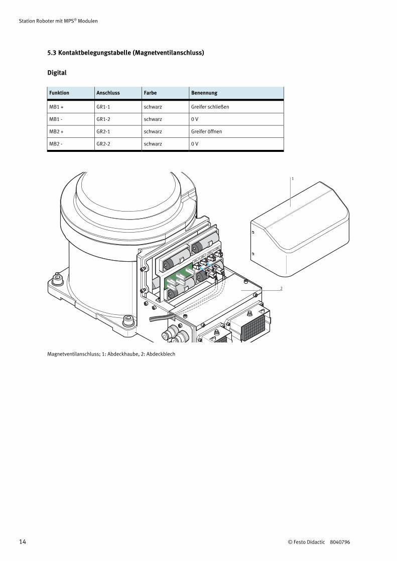
5.3 Kontaktbelegungstabelle (Magnetventilanschluss)
Digital
Funktion Anschluss Farbe Benennung
MB1 + GR1-1 schwarz Greifer schließen
MB1 - GR1-2 schwarz 0 V
MB2 + GR2-1 schwarz Greifer öffnen
MB2 - GR2-2 schwarz 0 V
GR1
GR2
GR3
GR4
1
2
Magnetventilanschluss; 1: Abdeckhaube, 2: Abdeckblech
Station Roboter mit MPS® Modulen
© Festo Didactic 8040796 15
6 Transport/Auspacken/Lieferumfang
6.1 Transport
Das MPS wird in einer Transportbox mit Palettenboden geliefert.
Die Transportbox darf ausschließlich mit geeigneten Hubwagen oder Gabelstaplern transportiert werden.
Die Transportbox muss gegen Umfallen und Herunterfallen gesichert sein.
Transportschäden sind unverzüglich dem Spediteur und Festo Didactic zu melden.
6.2 Auspacken
Beim Auspacken der Station das Füllmaterial der Transportbox vorsichtig entfernen. Beim Auspacken der
Station darauf achten, dass keine Aufbauten der Station beschädigt werden.
Beim Auspacken des Roboters und des Steuergerätes beachten Sie bitte die Hinweise im Kapitel 2 der
Technischen Handbücher der Firma Mitsubishi Electric
Mitsubishi Industrial Robot Instruction Manual RV-2F Series
ROBOT ARM SETUP & MAINTENANCE, Art.-Nr.: BFP-A8904, Version F
Mitsubishi Industrial Robot Standard Specifications Manual RV-2F-D Series
CR750-D/CR751-D Controller, Art.-Nr.: BFP-A8900, Version K
Nach dem Auspacken die Station auf mögliche Beschädigungen überprüfen. Beschädigungen sind
unverzüglich dem Spediteur und Festo Didactic zu melden.
6.3 Lieferumfang
Den Lieferumfang entsprechend dem Lieferschein und der Bestellung überprüfen. Mögliche Abweichungen
sind unverzüglich Festo Didactic zu melden.
Station Roboter mit MPS® Modulen
16 © Festo Didactic 8040796
7 Aufbau
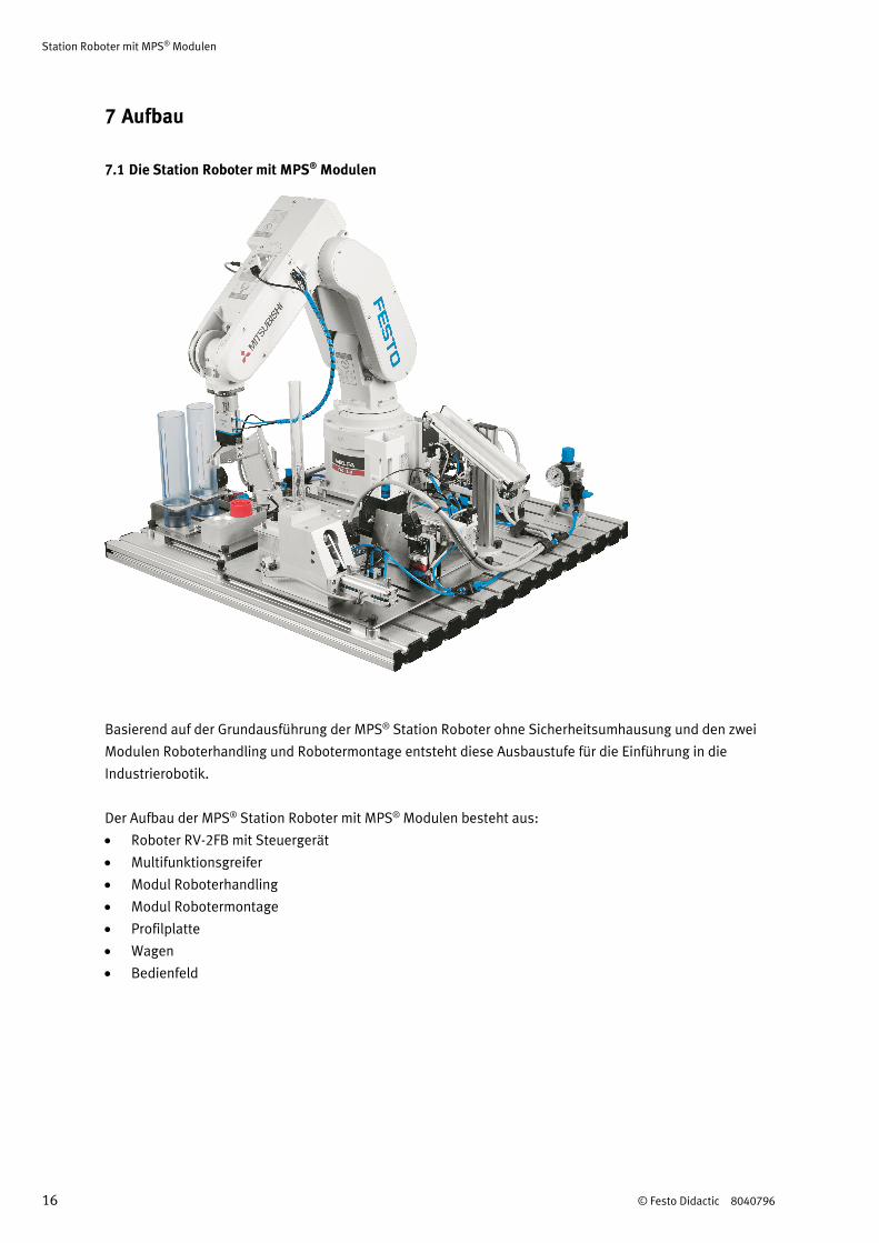
7.1 Die Station Roboter mit MPS® Modulen
Basierend auf der Grundausführung der MPS® Station Roboter ohne Sicherheitsumhausung und den zwei
Modulen Roboterhandling und Robotermontage entsteht diese Ausbaustufe für die Einführung in die
Industrierobotik.
Der Aufbau der MPS® Station Roboter mit MPS® Modulen besteht aus:
Roboter RV-2FB mit Steuergerät
Multifunktionsgreifer
Modul Roboterhandling
Modul Robotermontage
Profilplatte
Wagen
Bedienfeld
Station Roboter mit MPS® Modulen
© Festo Didactic 8040796 17
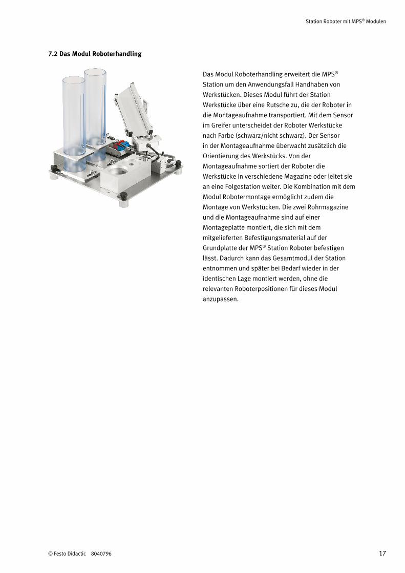
7.2 Das Modul Roboterhandling
Das Modul Roboterhandling erweitert die MPS®
Station um den Anwendungsfall Handhaben von
Werkstücken. Dieses Modul führt der Station
Werkstücke über eine Rutsche zu, die der Roboter in
die Montageaufnahme transportiert. Mit dem Sensor
im Greifer unterscheidet der Roboter Werkstücke
nach Farbe (schwarz/nicht schwarz). Der Sensor
in der Montageaufnahme überwacht zusätzlich die
Orientierung des Werkstücks. Von der
Montageaufnahme sortiert der Roboter die
Werkstücke in verschiedene Magazine oder leitet sie
an eine Folgestation weiter. Die Kombination mit dem
Modul Robotermontage ermöglicht zudem die
Montage von Werkstücken. Die zwei Rohrmagazine
und die Montageaufnahme sind auf einer
Montageplatte montiert, die sich mit dem
mitgelieferten Befestigungsmaterial auf der
Grundplatte der MPS® Station Roboter befestigen
lässt. Dadurch kann das Gesamtmodul der Station
entnommen und später bei Bedarf wieder in der
identischen Lage montiert werden, ohne die
relevanten Roboterpositionen für dieses Modul
anzupassen.
Station Roboter mit MPS® Modulen
18 © Festo Didactic 8040796
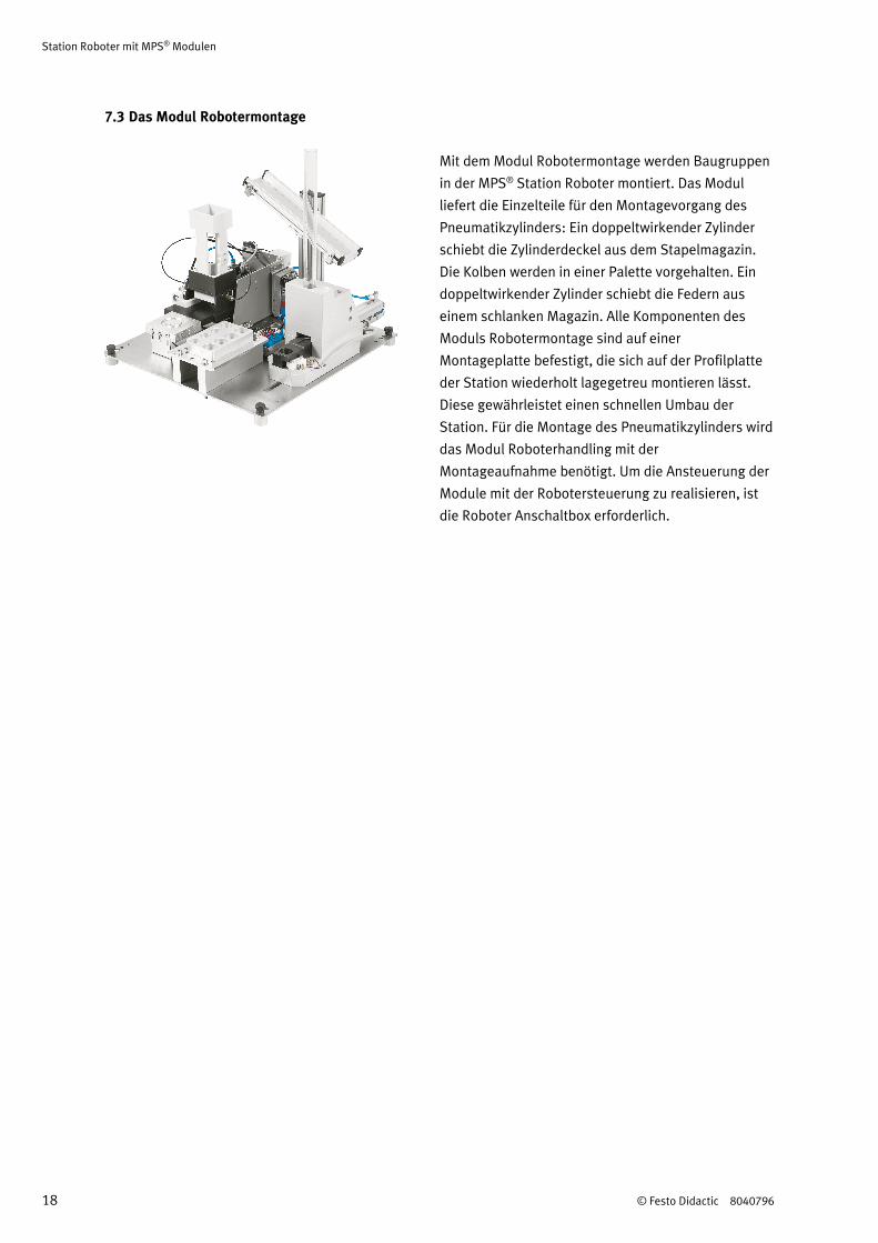
7.3 Das Modul Robotermontage
Mit dem Modul Robotermontage werden Baugruppen
in der MPS® Station Roboter montiert. Das Modul
liefert die Einzelteile für den Montagevorgang des
Pneumatikzylinders: Ein doppeltwirkender Zylinder
schiebt die Zylinderdeckel aus dem Stapelmagazin.
Die Kolben werden in einer Palette vorgehalten. Ein
doppeltwirkender Zylinder schiebt die Federn aus
einem schlanken Magazin. Alle Komponenten des
Moduls Robotermontage sind auf einer
Montageplatte befestigt, die sich auf der Profilplatte
der Station wiederholt lagegetreu montieren lässt.
Diese gewährleistet einen schnellen Umbau der
Station. Für die Montage des Pneumatikzylinders wird
das Modul Roboterhandling mit der
Montageaufnahme benötigt. Um die Ansteuerung der
Module mit der Robotersteuerung zu realisieren, ist
die Roboter Anschaltbox erforderlich.
Station Roboter mit MPS® Modulen
© Festo Didactic 8040796 19
8 Funktion
Das Werkstück „Grundkörper“ wird mit der Rutsche in die Aufnahme der Station Roboter transportiert. Der
Roboter nimmt das Werkstück dort mit einem Greifer auf. Das Werkstück wird zur Montageaufnahme
transportiert.
In der Position „Umgreifen“ bestimmt ein optischer Sensor im Greiferbacken die Farbe des Werkstücks
„Grundkörper“. Der Sensor unterscheidet schwarze und nicht schwarze Werkstücke. Mit einem optischen
Sensor im Modul Montageaufnahme wird die Orientierung des Grundkörpers kontrolliert. Das Werkstück
„Grundkörper“ wird in der Position „Montage“ abgelegt.
In Abhängigkeit von der Farbe des Grundkörpers werden Kolben von der Palette abgeholt und in den
Grundkörper eingesetzt. Für rote und silberne Grundkörper werden schwarze Kolben verwendet. Für
schwarze Grundkörper wird ein silberner Kolben verwendet. Anschließend wird die Feder abgeholt und
eingesetzt.
Der Deckel wird vom Deckelmagazin abgeholt. Mit einem optischen Sensor im Modul Montageaufnahme
wird die Orientierung des Deckels kontrolliert. Der Deckel wird montiert.
Die montierten Zylinder werden auf einer Rutsche abgelegt oder zu einer Folgestation transportiert.
Station Roboter mit MPS® Modulen
20 © Festo Didactic 8040796
9 Ablaufbeschreibung
Startvoraussetzung
Werkstück „Grundkörper“ in der Aufnahme der Station Roboter
Federmagazin gefüllt, keine Feder in Übergabeposition
Deckelmagazin gefüllt, kein Deckel in Übergabeposition
Kolbenpalette gefüllt
Ausgangsstellung
Roboter in Grundstellung
Greifer geöffnet
Ausschiebezylinder Federmagazin eingefahren
Ausschiebezylinder Deckelmagazin ausgefahren
Hinweis
Legen Sie das Werkstück nicht von Hand in die Aufnahme. Führen Sie das Werkstück der Aufnahme
immer über die Rutsche zu.
Ablauf
1. Mit SPS: Wird der START Taster gedrückt, werden ein Deckel und eine Feder ausgeschoben.
2. Wird der START Taster gedrückt und ein Werkstück in der Aufnahme erkannt, holt der Roboter das
Werkstück ab.
3. Das Werkstück wird zur Position „Umgreifen“ in der Montageaufnahme transportiert und abgelegt.
4. Die Farbe des Werkstücks wird ermittelt.
5. Das Werkstück wird gegriffen und die Orientierung wird geprüft.
Ablauf für Werkstück schwarz
6. Das Werkstück wird orientiert zur Position „Montage“ in der Montageaufnahme transportiert und
abgelegt.
7. Der Roboter holt einen silbernen Kolben vom Modul Palette und setzt den Kolben in den Grundkörper
ein.
8. Ohne SPS: Der Roboter startet das Federmagazin.
9. Der Roboter prüft, ob eine Feder verfügbar ist. Falls ja, greift er die Feder und setzt sie auf den Kolben.
10. Ohne SPS: Der Roboter startet das Deckelmagazin.
11. Der Roboter prüft, ob ein Deckel verfügbar ist. Falls ja, greift er den Deckel und steckt ihn auf den
Bolzen des Moduls Montageaufnahme. Der Roboter greift um und prüft die Orientierung des Deckels.
12. Der orientierte Deckel wird in den Grundkörper eingesetzt und durch Drehen eingerastet.
13. Der fertig montierte Zylinder wird gegriffen und auf der Rutsche abgesetzt.
Station Roboter mit MPS® Modulen
© Festo Didactic 8040796 21
Ablauf für Werkstück rot/silber
6. Das Werkstück wird orientiert zur Position „Montage“ in der Montageaufnahme transportiert und
abgelegt.
7. Der Roboter holt einen schwarzen Kolben vom Modul Palette und setzt den Kolben in den Grundkörper
ein.
8. Ohne SPS: Der Roboter startet das Federmagazin.
9. Der Roboter prüft, ob eine Feder verfügbar ist. Falls ja, greift er die Feder und setzt sie auf den Kolben.
10. Ohne SPS: Der Roboter startet das Deckelmagazin.
11. Der Roboter prüft, ob ein Deckel verfügbar ist. Falls ja, greift er den Deckel und steckt ihn auf den
Bolzen des Moduls Montageaufnahme. Der Roboter greift um und prüft die Orientierung des Deckels.
12. Der orientierte Deckel wird in den Grundkörper eingesetzt und durch Drehen eingerastet.
13. Der fertig montierte Zylinder wird gegriffen und auf der Rutsche abgesetzt.
Station Roboter mit MPS® Modulen
22 © Festo Didactic 8040796
10 Inbetriebnahme
Die MPS® Station wird vormontiert ausgeliefert. Sie erhalten
den Roboter,
das Steuergerät,
den Greifer und
die Profilplatte mit den montierten Baugruppen und Modulen
einzeln verpackt geliefert.
Hinweis
Bei einer Kombination von Stationen müssen eventuell Änderungen am mechanischen Aufbau und
der Position und Einstellung von Sensoren vorgenommen werden.
Alle Komponenten, Verschlauchungen und Verkabelungen sind eindeutig gekennzeichnet, so dass ein
Wiederherstellen aller Verbindungen problemlos möglich ist.
10.1 Arbeitsplatz
Zur Inbetriebnahme der MPS® Station Roboter mit den Beispielprogrammen benötigen Sie:
die montierte und justierte MPS® Station
ein Steuergerät
eine Teaching Box
ein Netzgerät 24 V DC, 4,5 A
eine Druckluftversorgung mit 600 kPa (6 bar), Saugleistung ca. 50 l/min
einen PC mit installierter Roboter Programmiersoftware CIROS® Studio oder CIROS®
Programming
Station Roboter mit MPS® Modulen
© Festo Didactic 8040796 23
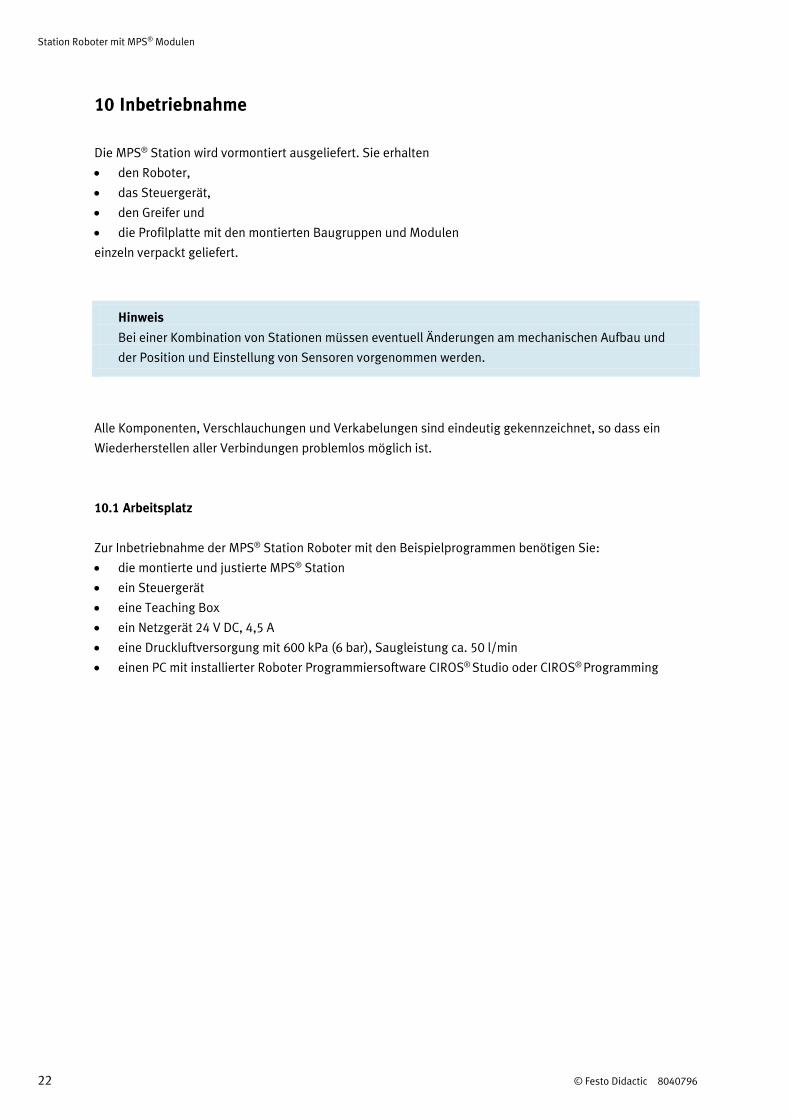
10.2 Kabelanschlüsse
Steuergerät – Roboter
Stecken Sie das Servo-Versorgungskabel (CN1) und das Signalkabel (CN2) am Steuergerät (Rückseite)
und am Roboter ein.
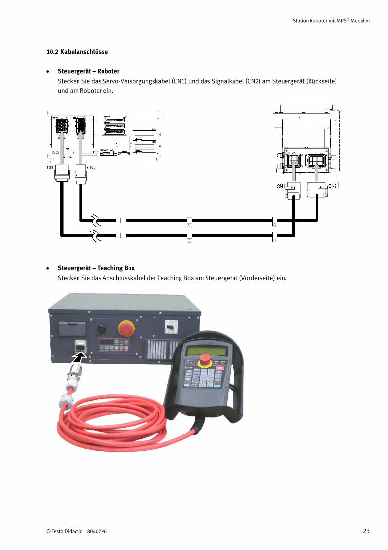
Steuergerät – Teaching Box
Stecken Sie das Anschlusskabel der Teaching Box am Steuergerät (Vorderseite) ein.

Station Roboter mit MPS® Modulen
24 © Festo Didactic 8040796
Steuergerät – Station
Zur Verbindung des Steuergeräts und der Station werden zwei spezielle E/A-Kabel verwendet.
Kabel A: ein Ende 24-polig, anderes Ende 40-polig
Kabel B: ein Ende 40-polig, anderes Ende 50-polig
Stecken Sie den 24-poligen Stecker von Kabel A in die Buchse XMA2 des E/A-Terminals der Station.
Stecken Sie den 50-poligen Stecker von Kabel B auf der Rückseite des Steuergeräts in die Buchse 1
der E/A-Schnittstelle SLOT1. Verbinden Sie die beiden Kabel.
A: Kabel A, b: Kabel B
Station Roboter mit MPS® Modulen
© Festo Didactic 8040796 25
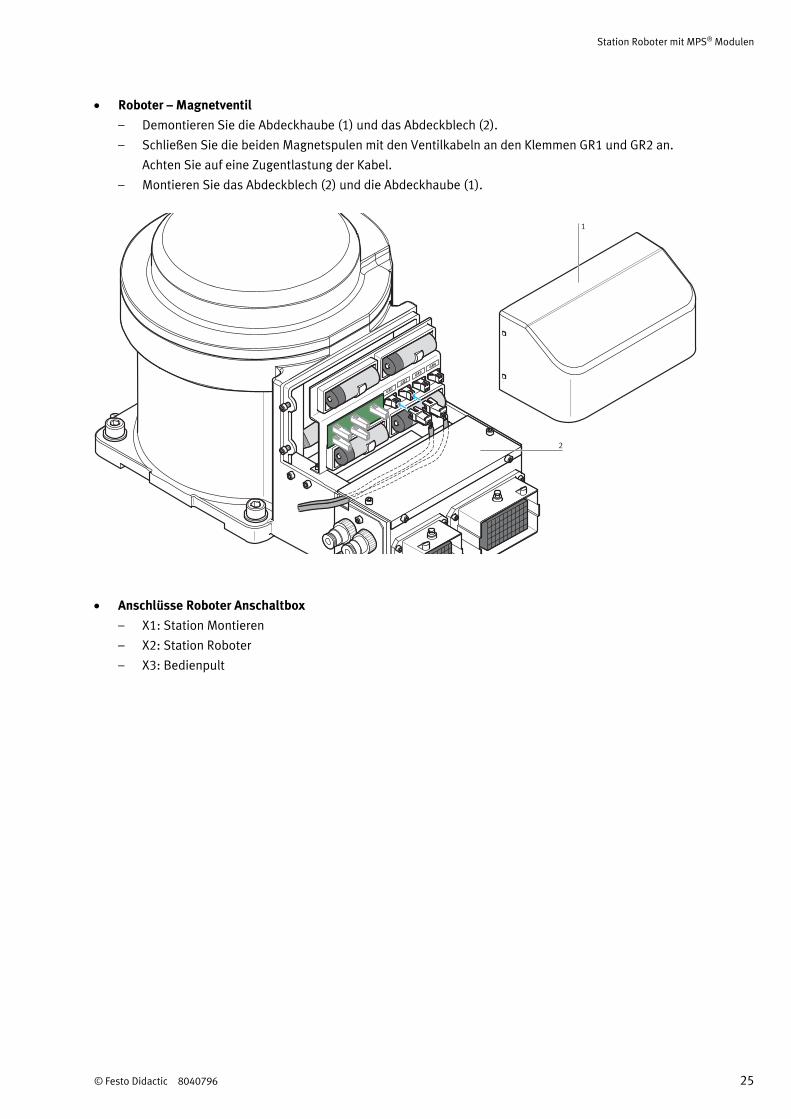
Roboter – Magnetventil
– Demontieren Sie die Abdeckhaube (1) und das Abdeckblech (2).
– Schließen Sie die beiden Magnetspulen mit den Ventilkabeln an den Klemmen GR1 und GR2 an.
Achten Sie auf eine Zugentlastung der Kabel.
– Montieren Sie das Abdeckblech (2) und die Abdeckhaube (1).
GR1
GR2
GR3
GR4
1
2
Anschlüsse Roboter Anschaltbox
– X1: Station Montieren
– X2: Station Roboter
– X3: Bedienpult
Station Roboter mit MPS® Modulen
26 © Festo Didactic 8040796
Anschlüsse der Sicherheitseinrichtungen
Die Stecker der Sicherheitseinrichtungen, müssen an die oberen zwei CNUSR11 und CNUSR12
Schnittstellen angeschlossen werden
Anschlüsse Erdungsset
Das Erdungsset dient zum Erden des Roboters und der Profilplatte. Beide Komponenten werden mit der
Robotersteuerung elektrisch leitend verbunden.
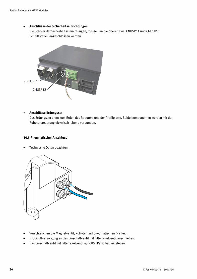
10.3 Pneumatischer Anschluss
Technische Daten beachten!
Verschlauchen Sie Magnetventil, Roboter und pneumatischen Greifer.
Druckluftversorgung an das Einschaltventil mit Filterregelventil anschließen.
Das Einschaltventil mit Filterregelventil auf 600 kPa (6 bar) einstellen.
Station Roboter mit MPS® Modulen
© Festo Didactic 8040796 27
10.4 Spannungsversorgung
Die Sensoren und Aktoren der Station werden über ein Netzgerät mit 24 V Gleichspannung (max. 4,5 A)
versorgt.
Die Spannungsversorgung der kompletten Station erfolgt über zwei Netzanschlüsse.
10.5 Inbetriebnahme des Robotersystems
Einzelheiten zur Inbetriebnahme des Robotersystems entnehmen Sie bitte dem Technischen Handbuch
der Firma Mitsubishi Electric.
Mitsubishi Industrial Robot Instruction Manual RV-2F Series
ROBOT ARM SETUP & MAINTENANCE, Art.-Nr.: BFP-A8904, Version F
Führen Sie folgende Schritte durch:
Einstellen der Grundposition
Station Roboter mit MPS® Modulen
28 © Festo Didactic 8040796
10.6 Roboter Programm laden
Steuergerät: CR750-D
Programmiersoftware: CIROS® Studio oder CIROS® Programming
1. PC und Steuergerät mit dem Programmierkabel verbinden
2. Steuergerät einschalten
3. Netzgerät einschalten
4. Druckluftversorgung einschalten
5. NOT-AUS Taster entriegeln
6. Starten Sie die Roboter Programmiersoftware.
7. Es stehen 4 unterschiedliche Programme zur Verfügung:
– 3.mb5: Mit Orientierung
– 4.mb5: Ohne Orientierung
– 5.mb5: Ohne Orientierung und ohne Positionsvariable
– 6.mb5: Ohne Orientierung, Positionsvariable und Unterprogramme
– 12.mb5: Montieren mit Roboter
Laden Sie das gewünschte Programm aus dem Verzeichnis
Quellen\Roboter Programme\RV-2FB\Roboter der mitgelieferten CD-ROM
8. Stellen Sie den MODE Schalter am Steuergerät in die Position AUTO
9. Laden Sie das Programm und die Positionsliste in das Steuergerät.
10.7 Positionen teachen
Zum Teachen der Positionen gehen Sie wie folgt vor:
1. Schalten Sie das Steuergerät ein.
2. Entriegeln Sie den NOT-AUS Taster.
3. Quittieren Sie Fehlermeldungen durch Drücken der Taste RESET am Steuergerät oder durch
Drücken der Taste ERROR RESET an der Teaching Box.
4. Stellen Sie den MODE Schalter am Steuergerät in die Position TEACH.
5. Drehen Sie den Schlüsselschalter der Teaching Box in Position ENABLE.
6. Das Startdisplay erhalten Sie durch Drücken der Taste MENU.
Wählen Sie 1) TEACH durch Drücken der Taste INP/EXE.
7. Geben Sie die Programmnummer des aktuellen Programms ein. Drücken Sie die Taste INP/EXE.
8. Drücken Sie die Taste POS. Mit den Tasten +/FORWD bzw. -/BACKWD können Sie die einzelnen
Positionen auswählen. Wählen Sie die Position.
9. Reduzieren Sie durch Drücken der Taste –/BACKWD die Verfahrgeschwindigkeit.
10. Drücken Sie den Totmannschalter und die Taste STEP/MOVE. Wenn die Servomotoren
eingeschaltet haben drücken Sie die Taste INP/EXE. Die gewählte Position wird angefahren.
Achten Sie hierbei besonders auf mögliche Kollisionen.
11. Kontrollieren Sie die angefahrene Position. Ist die Position korrekt, gehen Sie zu Schritt 8 und
prüfen die nächste Position. Ist die Position nicht korrekt gehen Sie weiter mit Schritt 12.
Station Roboter mit MPS® Modulen
© Festo Didactic 8040796 29
12. Drücken Sie den Totmannschalter auf der Rückseite der Teaching Box.
13. Wählen Sie ein Koordinatensystem, z.B. XYZ.
14. Drücken Sie die Taste STEP/MOVE und bewegen Sie den Roboter durch Drücken der Tasten –X,
+X, –Y, +Y, –Z, +Z, –A, +A, –B, +B.
15. Wenn Sie die genaue Position angefahren haben, drücken Sie Taste ADD zweimal. Die aktuelle
Position wird in die Positionsliste übernommen.
16. Gehen Sie zu Schritt 8 und prüfen Sie die nächste Position.
Hinweis
Durch Drücken der Tasten HAND und –C bzw. HAND und +C schließen bzw. öffnen Sie den Greifer
10.7.1 Jog-Operation Modus
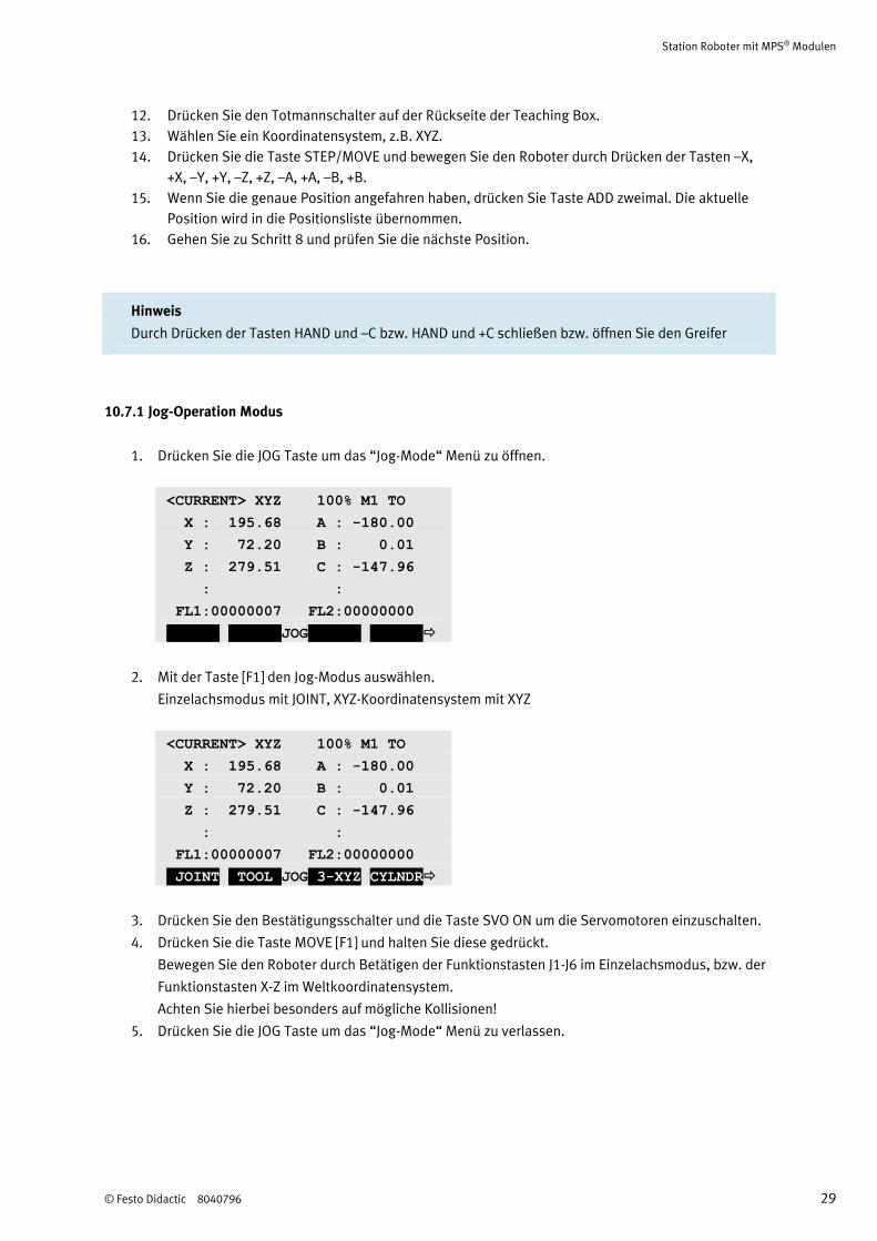
1. Drücken Sie die JOG Taste um das “Jog-Mode“ Menü zu öffnen.
<CURRENT> XYZ 100% M1 TO
X : 195.68 A : -180.00
Y : 72.20 B : 0.01
Z : 279.51 C : -147.96
: :
FL1:00000007 FL2:00000000
ADD.AX WORK JOG CLOSE
2. Mit der Taste [F1] den Jog-Modus auswählen.
Einzelachsmodus mit JOINT, XYZ-Koordinatensystem mit XYZ
<CURRENT> XYZ 100% M1 TO
X : 195.68 A : -180.00
Y : 72.20 B : 0.01
Z : 279.51 C : -147.96
: :
FL1:00000007 FL2:00000000
JOINT TOOL JOG 3-XYZ CYLNDR
3. Drücken Sie den Bestätigungsschalter und die Taste SVO ON um die Servomotoren einzuschalten.
4. Drücken Sie die Taste MOVE [F1] und halten Sie diese gedrückt.
Bewegen Sie den Roboter durch Betätigen der Funktionstasten J1-J6 im Einzelachsmodus, bzw. der
Funktionstasten X-Z im Weltkoordinatensystem.
Achten Sie hierbei besonders auf mögliche Kollisionen!
5. Drücken Sie die JOG Taste um das “Jog-Mode“ Menü zu verlassen.
Station Roboter mit MPS® Modulen
30 © Festo Didactic 8040796
10.7.2 Hand-Operation Modus
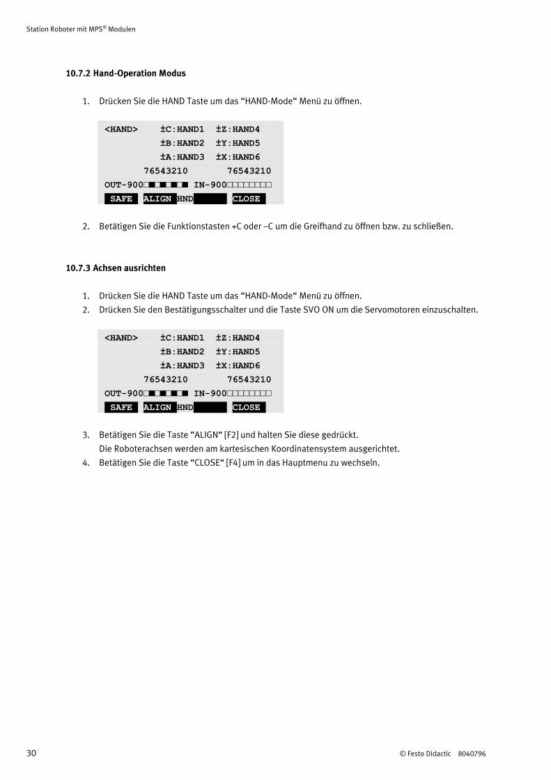
1. Drücken Sie die HAND Taste um das “HAND-Mode“ Menü zu öffnen.
<HAND> ±C:HAND1 ±Z:HAND4
±B:HAND2 ±Y:HAND5
±A:HAND3 ±X:HAND6
76543210 76543210
OUT-900□■□■□■□■ IN-900□□□□□□□□
SAFE ALIGN HND CLOSE
2. Betätigen Sie die Funktionstasten +C oder –C um die Greifhand zu öffnen bzw. zu schließen.
10.7.3 Achsen ausrichten
1. Drücken Sie die HAND Taste um das “HAND-Mode“ Menü zu öffnen.
2. Drücken Sie den Bestätigungsschalter und die Taste SVO ON um die Servomotoren einzuschalten.
<HAND> ±C:HAND1 ±Z:HAND4
±B:HAND2 ±Y:HAND5
±A:HAND3 ±X:HAND6
76543210 76543210
OUT-900□■□■□■□■ IN-900□□□□□□□□
SAFE ALIGN HND CLOSE
3. Betätigen Sie die Taste “ALIGN“ [F2] und halten Sie diese gedrückt.
Die Roboterachsen werden am kartesischen Koordinatensystem ausgerichtet.
4. Betätigen Sie die Taste “CLOSE“ [F4] um in das Hauptmenu zu wechseln.
Station Roboter mit MPS® Modulen
© Festo Didactic 8040796 31
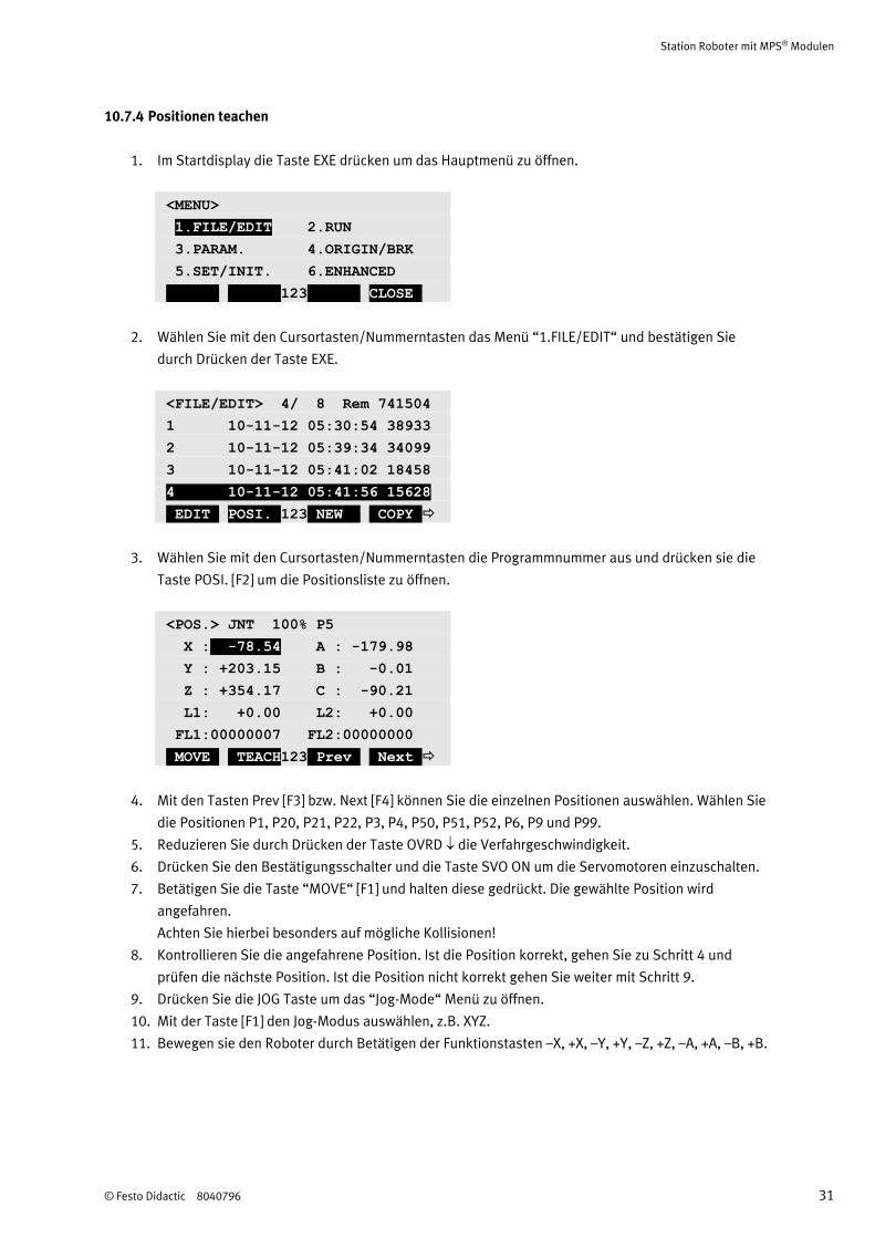
10.7.4 Positionen teachen
1. Im Startdisplay die Taste EXE drücken um das Hauptmenü zu öffnen.
<MENU>
1.FILE/EDIT 2.RUN
3.PARAM. 4.ORIGIN/BRK
5.SET/INIT. 6.ENHANCED
123 CLOSE
2. Wählen Sie mit den Cursortasten/Nummerntasten das Menü “1.FILE/EDIT“ und bestätigen Sie
durch Drücken der Taste EXE.
<FILE/EDIT> 4/ 8 Rem 741504
1 10-11-12 05:30:54 38933
2 10-11-12 05:39:34 34099
3 10-11-12 05:41:02 18458
4 10-11-12 05:41:56 15628
EDIT POSI. 123 NEW COPY
3. Wählen Sie mit den Cursortasten/Nummerntasten die Programmnummer aus und drücken sie die
Taste POSI. [F2] um die Positionsliste zu öffnen.
<POS.> JNT 100% P5
X : -78.54 A : -179.98
Y : +203.15 B : -0.01
Z : +354.17 C : -90.21
L1: +0.00 L2: +0.00
FL1:00000007 FL2:00000000
MOVE TEACH123 Prev Next
4. Mit den Tasten Prev [F3] bzw. Next [F4] können Sie die einzelnen Positionen auswählen. Wählen Sie
die Positionen P1, P20, P21, P22, P3, P4, P50, P51, P52, P6, P9 und P99.
5. Reduzieren Sie durch Drücken der Taste OVRD die Verfahrgeschwindigkeit.
6. Drücken Sie den Bestätigungsschalter und die Taste SVO ON um die Servomotoren einzuschalten.
7. Betätigen Sie die Taste “MOVE“ [F1] und halten diese gedrückt. Die gewählte Position wird
angefahren.
Achten Sie hierbei besonders auf mögliche Kollisionen!
8. Kontrollieren Sie die angefahrene Position. Ist die Position korrekt, gehen Sie zu Schritt 4 und
prüfen die nächste Position. Ist die Position nicht korrekt gehen Sie weiter mit Schritt 9.
9. Drücken Sie die JOG Taste um das “Jog-Mode“ Menü zu öffnen.
10. Mit der Taste [F1] den Jog-Modus auswählen, z.B. XYZ.
11. Bewegen sie den Roboter durch Betätigen der Funktionstasten –X, +X, –Y, +Y, –Z, +Z, –A, +A, –B, +B.
Station Roboter mit MPS® Modulen
32 © Festo Didactic 8040796
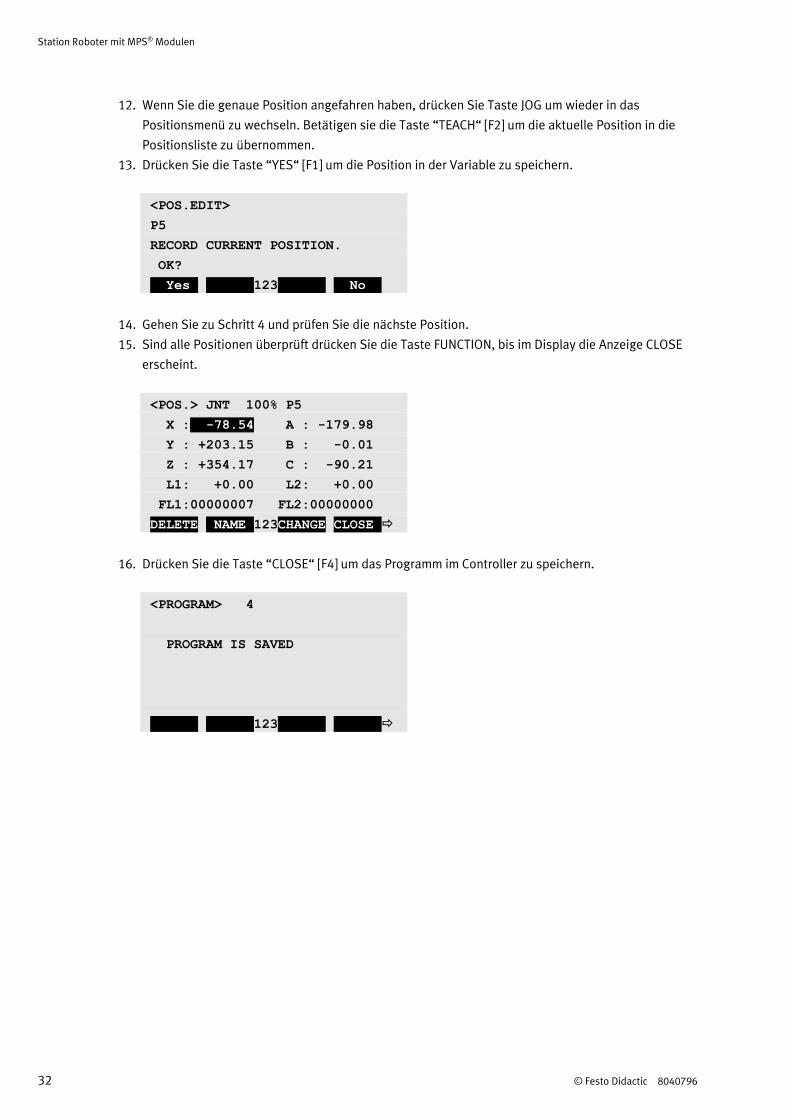
12. Wenn Sie die genaue Position angefahren haben, drücken Sie Taste JOG um wieder in das
Positionsmenü zu wechseln. Betätigen sie die Taste “TEACH“ [F2] um die aktuelle Position in die
Positionsliste zu übernommen.
13. Drücken Sie die Taste “YES“ [F1] um die Position in der Variable zu speichern.
<POS.EDIT>
P5
RECORD CURRENT POSITION.
OK?
Yes 123 No
14. Gehen Sie zu Schritt 4 und prüfen Sie die nächste Position.
15. Sind alle Positionen überprüft drücken Sie die Taste FUNCTION, bis im Display die Anzeige CLOSE
erscheint.
<POS.> JNT 100% P5
X : -78.54 A : -179.98
Y : +203.15 B : -0.01
Z : +354.17 C : -90.21
L1: +0.00 L2: +0.00
FL1:00000007 FL2:00000000
DELETE NAME 123CHANGE CLOSE
16. Drücken Sie die Taste “CLOSE“ [F4] um das Programm im Controller zu speichern.
<PROGRAM> 4
PROGRAM IS SAVED
123
Station Roboter mit MPS® Modulen
© Festo Didactic 8040796 33
10.8 Ablauf starten
1. Überprüfen Sie Spannungsversorgung und Druckluftversorgung.
2. Entnehmen Sie Werkstücke an Übergabestellen von Modulen oder Stationen vor dem Richten von Hand.
3. Führen Sie den Richtvorgang durch. Der Richtvorgang wird mit dem leuchtenden RICHTEN Taster
angefordert und nach dem Betätigen des Tasters durchgeführt.
4. Legen Sie ein Werkstück auf die Eingangsrutsche.
5. Starten Sie den Ablauf der Station. Der Start wird mit dem leuchtenden START Taster angefordert und
nach dem Betätigen des Tasters durchgeführt.
Hinweise
Sie können den Ablauf jederzeit durch Drücken des NOT-HALT Tasters oder durch Drücken des
STOP Tasters unterbrechen.
Bei einer Kombination mehrerer Stationen gilt:
Richten der einzelnen Stationen erfolgt entgegen dem Materialfluss.
Der Leuchtmelder „Federmagazin leer“ leuchtet, wenn keine Druckfedern im Magazin
vorhanden sind.
Der Leuchtmelder „Deckelmagazin leer“ leuchtet, wenn keine Deckel im Magazin vorhanden
sind.
Station Roboter mit MPS® Modulen
34 © Festo Didactic 8040796
11 Wartung und Pflege
Die Station Robotermit MPS® Modulen ist weitestgehend wartungsfrei. In regelmäßigen Abständen sollten:
die Linsen der optischen Sensoren, der Faseroptiken sowie Reflektoren
die aktive Fläche des Näherungsschalters
die gesamte Station
mit einem weichen, fuselfreien Tuch oder Pinsel gereinigt werden.
Hinweise
• Es dürfen keine aggressiven oder scheuernden Reinigungsmittel verwendet werden.
• Verwenden Sie zum Reinigen der Scheiben der Sicherheitsumhausung nur klares Wasser.
11.1 Jährlicher Austausch der Pufferbatterien
Jedes Jahr ist ein Austausch der Pufferbatterien notwendig. Die Pufferbatterien stellen sicher, dass die
Encoder-Positionsdaten auch im ausgeschalteten Zustand gespeichert bleiben. Ist die Lebensdauer der
Batterien abgelaufen, wird eine Fehlermeldung ausgelöst. Die Pufferbatterien sind dann schnellstmöglich zu
ersetzen, um einen Verlust der Daten zu verhindern
Hinweise
• Beachten Sie die Hinweise in den Bedienungsanleitungen von Mitsubishi.
• Beachten Sie die Montageanleitung der Sicherheitsumhausung.
12 Weitere Informationen und Aktualisierungen
Weiter Informationen und Aktualisierungen zur Technischen Dokumentation der MPS Stationen finden Sie
im Internet unter der Adresse:
www.festo-didactic.com > Service > MPS® Mechatronische Systeme
© Festo Didactic 8040796 35
Table of contents
1 General requirements for operating the devices ________________________________________ 37
2 Pictograms ______________________________________________________________________ 37
3 Use for intended purpose __________________________________________________________ 38
4 For your safety ___________________________________________________________________ 38
4.1 Important information _____________________________________________________________ 38
4.2 Obligations of the operating company ________________________________________________ 39
4.3 Obligations of the trainees __________________________________________________________ 39
4.4 Dangers associated with the modular production system _________________________________ 39
4.5 Working safely ___________________________________________________________________ 39
5 Technical data ___________________________________________________________________ 43
5.1 Pin allocation table „station“ (X0 at robot controller) ____________________________________ 44
5.2 Pin allocation table (sensor plug Hand CON1H) _________________________________________ 45
5.3 Pin allocation table (solenoid valve connection) ________________________________________ 46
6 Transport, unpacking, scope of delivery ______________________________________________ 47
6.1 Transport ________________________________________________________________________ 47
6.2 Unpacking _______________________________________________________________________ 47
6.3 Scope of delivery _________________________________________________________________ 47
7 Layout __________________________________________________________________________ 48
7.1 The Robot station with MPS® modules ________________________________________________ 48
7.2 Robot handling module ____________________________________________________________ 49
7.3 Robot assembly module ____________________________________________________________ 50
8 Function ________________________________________________________________________ 51
9 Sequence description _____________________________________________________________ 52
10 Commissioning ___________________________________________________________________ 54
10.1 Workstation ______________________________________________________________________ 54
10.2 Cable connections ________________________________________________________________ 55
10.3 Pneumatic connection _____________________________________________________________ 58
10.4 Voltage supply ___________________________________________________________________ 59
10.5 Commissioning the robot system ____________________________________________________ 59
Table of contents
36 © Festo Didactic 8040796
10.6 Loading the robot program _________________________________________________________ 60
10.7 Teaching positions ________________________________________________________________ 60
10.7.1 Jog-operation mode _______________________________________________________________ 61
10.7.2 Hand-operation mode _____________________________________________________________ 62
10.7.3 Align axis ________________________________________________________________________ 62
10.7.4 Teaching positions ________________________________________________________________ 63
10.8 Starting the sequence _____________________________________________________________ 65
11 Maintenance and care _____________________________________________________________ 66
11.1 Replacement of batteries ___________________________________________________________ 66
12 Further information and updates ____________________________________________________ 66
Robot station with MPS® modules
© Festo Didactic 8040796 37
1 General requirements for operating the devices
The laboratory or the classroom must be equipped with the following devices:
An emergency-off device must be provided.
– At least one emergency-off device must be located within, and one outside the laboratory or
the classroom.
The laboratory or classroom must be secured so that the operating voltage and compressed air supply
cannot be activated by any unauthorised persons, for example by means of:
– A key switch
– A lockable on-off valve
The laboratory or classroom must be protected by residual current devices (RCDs).
– Type B residual current circuit breakers with a residual current rating of ≤ 30 mA
The laboratory or classroom must be protected by overcurrent protection devices.
– Fuses or circuit breakers
The laboratory or classroom must be overseen by a supervisor.
– A supervisor is a qualified electrician or a person who has received appropriate instruction,
has knowledge of the respective safety requirements and safety regulations and
whose training has been documented accordingly.
No damaged or defective devices may be used.
– Damaged devices must be barred from further use and removed from the laboratory or classroom.
General requirements for safe operation of the devices:
Do not lay cables over hot surfaces.
– Hot surfaces are identified with a corresponding warning symbol.
Maximum permissible current loads for cables and devices must not be exceeded.
– Always compare the current ratings of the device, the cable and the fuse.
– In the event that these are not the same, use a separate upstream fuse in order to
provide appropriate overcurrent protection.
Devices with an earth terminal must always be grounded.
– If an earth connection (green-yellow laboratory socket) is available, it must always be
connected to protective earth. Protective earth must always be connected first (before voltage),
and must always be disconnected last (after voltage).
If not otherwise specified in the technical data, the device is not equipped with an integrated fuse.
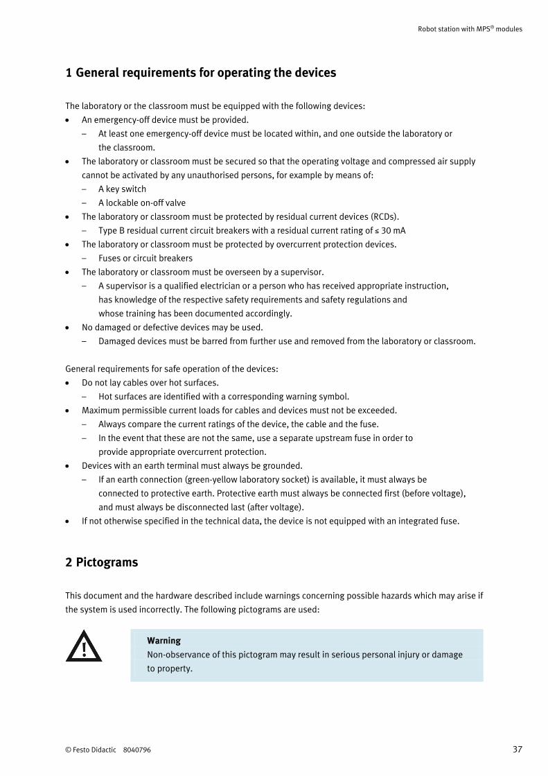
2 Pictograms
This document and the hardware described include warnings concerning possible hazards which may arise if
the system is used incorrectly. The following pictograms are used:
Warning
Non-observance of this pictogram may result in serious personal injury or damage
to property.
Robot station with MPS® modules
38 © Festo Didactic 8040796
3 Use for intended purpose
The stations of the Modular Production System may only be used:
For their intended purpose in teaching and training applications
When their safety functions are in flawless condition
The stations are designed in accordance with the latest technology as well as recognised safety rules.
However, life and limb of the user and third parties may be endangered, and the components may be
impaired if they are used incorrectly.
The learning system from Festo Didactic has been developed and produced exclusively for training and
continuing vocational education in the field of automation technology. The training company and/or trainers
must ensure that all trainees observe the safety precautions described in this workbook.
Festo Didactic hereby excludes any and all liability for damages suffered by trainees, the training company
and/or any third parties, which occur during use of the equipment sets in situations which serve any
purpose other than training and/or vocational education, unless such damages have been caused by Festo
Didactic due to malicious intent or gross negligence.
4 For your safety
4.1 Important information
Fundamental prerequisites for safe use and trouble-free operation of the MPS include knowledge of basic
safety precautions and safety regulations. This manual includes the most important instructions for safe use
of the MPS.
In particular, the safety precautions must be adhered to by all persons who work with the MPS.
Beyond this, all pertinent accident prevention rules and regulations, which are applicable at the respective
location of use, must be adhered to.
Robot station with MPS® modules
© Festo Didactic 8040796 39
4.2 Obligations of the operating company
The operating company undertakes to allow only those persons to work with the MPS who:
Are familiar with the basic regulations regarding work safety and accident prevention and have been
instructed in the use of the MPS
Have read and understood the chapter concerning safety and the warnings in this manual
Personnel should be tested at regular intervals for safety-conscious work habits.
4.3 Obligations of the trainees
All persons who have been entrusted to work with the MPS undertake to complete the following steps
before beginning work:
Read the chapter concerning safety and the warnings in this manual
Familiarise themselves with the basic regulations regarding work safety and accident prevention
4.4 Dangers associated with the modular production system
The MPS is laid out in accordance with the latest technology, as well as recognised safety rules.
Nevertheless, life and limb of the user and third parties may be endangered, and the machine or other
property may be damaged during its use.
The MPS may only be used:
For its intended purpose
When its safety functions are in flawless condition
Malfunctions which may impair safety must be eliminated immediately!
4.5 Working safely
General information
Trainees may only work with the circuits under the supervision of a trainer.
Electrical devices (e.g. power supply units, compressors and hydraulic power units) may only be
operated in training rooms which are equipped with residual current devices (RCDs).
Observe the specifications included in the technical data for the individual components, and in
particular all safety instructions!
Robot station with MPS® modules
40 © Festo Didactic 8040796
Malfunctions which may impair safety must not be generated in the training environment, and must be
eliminated immediately.
Wear personal protective equipment (safety goggles, safety shoes) when working on circuits.
Mechanical safety
Only reach into the setup when it is at a complete standstill.
Mount all of the components securely onto the slotted profile plate.
Limit switches may not be actuated frontally.
Risk of injury during troubleshooting!
Use a tool to actuate the limit switches, for example a screwdriver.
Set all components up so that activation of switches and disconnectors is not made difficult.
Adhere to the instructions regarding positioning of the components.
Electrical safety
Use extra-low voltage only (max. 24 V DC).
Only establish or interrupt electrical connections when there is no voltage present!
Use only connecting cables with safety plugs for electrical connections.
Pull the plug only when disconnecting connecting cables; never pull the cable.
Industrial robot
Observe all information in the safety manual for Mitsubishi’s MELFA industrial robots.
Transporting the robot
– If the robot will be transported again after installation, it must be ensured that the brakes for
the robot’s arm are released and the arm is returned to the transport position.
The robot must never be carried or transported with its arm extended.
– Before transporting the robot again, the transport locking devices must be reinstalled.
Set up a safety barrier or enclosure around the robot, so that potential danger can be
ruled out in the event that anyone approaches the robot heedlessly.
Install a safety lock which prevents the door from being opened if an operator attempts to pass the
barrier (within the safety zone) while the robot is running, or by means of which the robot’s servo power
supply is switched off and peripheral devices are automatically stopped (by switching off the servo
power supply). Connect the cable for the signal from this safety lock directly to the robot and the
peripheral devices, and not to a secondary device (e.g. PLC). In the case of Mitsubishi robots, connect
the cable to the input terminal of the emergency stop switch or the door switch.
Install the robot system so that the controller is located outside of the safety zone.
Robot station with MPS® modules
© Festo Didactic 8040796 41
Attach a manual emergency stop switch in an easy to reach location in close proximity to the robot and
connect it to the input terminal of the controller’s emergency off circuit.
Configure the system so that the robot’s operating status (i.e. execution program mode, stop status,
servo on-status, error status etc.) can be easily checked externally with the help of visual indicators or
the like.
In order to ensure the safety of operating personnel, all errors should be indicated in direct proximity to
the robot by means of audible and visible signals.
In order to avoid electric shock and electrostatic discharge, to improve interference immunity and to
prevent unnecessary electromagnetic radiation, make sure that the robot and the controller are properly
grounded.
If an operator needs to enter the area behind the barrier while the servo power supply is switched on for
the purpose of training, adjustment or the like, he must wear a hard hat. During teach-in programming,
the servo on-mode must be executed via the dead man’s switch so that the servo power supply can be
switched off at any time and enough room for the operator is available in order to avoid potential
hazards.
Select a team member as a responsible party and make sure that hand signals and commands are fully
understood, and that they serve to ensure safety.
Cables may only be connected when the power supply is switched off. Risk of electric shock.
Do not touch any of the robot’s moving parts during operation. Switch off the robot before performing
any type of work within its range.
Because its integrated emergency stop device is not operational, do not keep an unconnected teaching
box in proximity to the robot.
Pneumatic safety
Do not exceed the maximum permissible pressure of 600 kPa (6 bar).
Do not switch on the compressed air until all tubing connections have been completed and secured.
Do not disconnect tubing while under pressure.
Risk of injury when switching compressed air on!
Cylinders may advance and retract automatically.
Danger of accident due to advancing cylinders!
– Always position pneumatic cylinders so that the piston’s working space is unobstructed
over the entire stroke range.
– Make sure that the piston rod cannot collide with any rigid components of the setup.
Danger of accident due to tubing slipping off!
– Use shortest possible tubing connections.
– In the event that tubing slips off:
Switch compressed air supply off immediately.
Robot station with MPS® modules
42 © Festo Didactic 8040796
Setting up the pneumatic circuit:
Connect the devices with plastic tubing with an outside diameter of 4 or 6 mm. Push the tubing into the
push-in connector as far as it will go.
Switch the compressed air supply off before dismantling the circuit.
Dismantling the pneumatic circuit:
Press the blue release ring down, after which the tubing can be pulled out.
Robot station with MPS® modules
© Festo Didactic 8040796 43
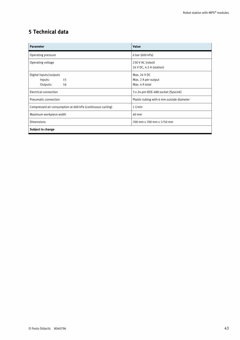
5 Technical data
Parameter Value
Operating pressure 6 bar (600 kPa)
Operating voltage 230 V AC (robot)
24 V DC, 4.5 A (station)
Digital inputs/outputs
Inputs: 15
Outputs: 16
Max. 24 V DC
Max. 2 A per output
Max. 4 A total
Electrical connection 3 x 24-pin IEEE-488 socket (SysLink)
Pneumatic connection Plastic tubing with 6 mm outside diameter
Compressed air consumption at 600 kPa (continuous cycling) 1 l/min
Maximum workpiece width 40 mm
Dimensions 700 mm x 700 mm x 1750 mm
Subject to change
Robot station with MPS® modules
44 © Festo Didactic 8040796
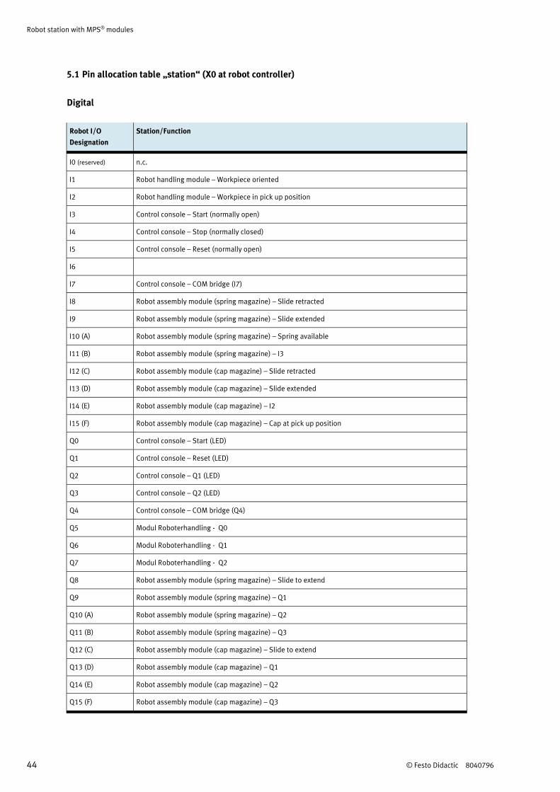
5.1 Pin allocation table „station“ (X0 at robot controller)
Digital
Robot I/O
Designation
Station/Function
I0 (reserved) n.c.
I1 Robot handling module – Workpiece oriented
I2 Robot handling module – Workpiece in pick up position
I3 Control console – Start (normally open)
I4 Control console – Stop (normally closed)
I5 Control console – Reset (normally open)
I6
I7 Control console – COM bridge (I7)
I8 Robot assembly module (spring magazine) – Slide retracted
I9 Robot assembly module (spring magazine) – Slide extended
I10 (A) Robot assembly module (spring magazine) – Spring available
I11 (B) Robot assembly module (spring magazine) – I3
I12 (C) Robot assembly module (cap magazine) – Slide retracted
I13 (D) Robot assembly module (cap magazine) – Slide extended
I14 (E) Robot assembly module (cap magazine) – I2
I15 (F) Robot assembly module (cap magazine) – Cap at pick up position
Q0 Control console – Start (LED)
Q1 Control console – Reset (LED)
Q2 Control console – Q1 (LED)
Q3 Control console – Q2 (LED)
Q4 Control console – COM bridge (Q4)
Q5 Modul Roboterhandling - Q0
Q6 Modul Roboterhandling - Q1
Q7 Modul Roboterhandling - Q2
Q8 Robot assembly module (spring magazine) – Slide to extend
Q9 Robot assembly module (spring magazine) – Q1
Q10 (A) Robot assembly module (spring magazine) – Q2
Q11 (B) Robot assembly module (spring magazine) – Q3
Q12 (C) Robot assembly module (cap magazine) – Slide to extend
Q13 (D) Robot assembly module (cap magazine) – Q1
Q14 (E) Robot assembly module (cap magazine) – Q2
Q15 (F) Robot assembly module (cap magazine) – Q3

Robot station with MPS® modules
© Festo Didactic 8040796 45
5.2 Pin allocation table (sensor plug Hand CON1H)
Digital
Function Terminal
designation (Pin)
Colour Designation
HC1 A1 (7) Black Workpiece not black
HC2 A2
HC3 A3
HC4 A4
--- A5 Reserved
--- A6 Reserved
--- B1 Reserved
--- B2 Reserved
24V B3 (3) Brown 24 V Power supply
0V (COM) B4 (4) blue 0 V Power supply
--- B5 Reserved
--- B6 Reserved
Sensor plug Hand CON1H

Robot station with MPS® modules
46 © Festo Didactic 8040796
5.3 Pin allocation table (solenoid valve connection)
Digital
Function Terminal Colour Designation
MB1 + GR1-1 Black Close gripper
MB1 - GR1-2 Black 0 V
MB2 + GR2-1 Black Open gripper
MB2 - GR2-2 Black 0 V
GR1
GR2
GR3
GR4
1
2
Solenoid valve connection; 1: cover, 2: cover plate
Robot station with MPS® modules
© Festo Didactic 8040796 47
6 Transport, unpacking, scope of delivery
6.1 Transport
MPS stations are delivered in a crate on a pallet.
The crate may only be transported with a suitable pallet jack or forklift. The crate must be secured against
tipping over and falling.
The freight forwarder and Festo Didactic must be notified of any transport damage without delay.
6.2 Unpacking
Carefully remove the padding material from the crate when unpacking the station. When unpacking the
station, make sure that none of its assemblies have been damaged.
When unpacking the robot and the robot controller take care of the notes in the Mitsubishi Electric manuals
Mitsubishi Industrial Robot Instruction Manual RV-2F Series
ROBOT ARM SETUP & MAINTENANCE, Art.-Nr.: BFP-A8904, Version F
Mitsubishi Industrial Robot Standard Specifications Manual RV-2F-D Series
CR750-D/CR751-D Controller, Art.-Nr.: BFP-A8900, Version K
Examine the station for possible damage after unpacking. The freight forwarder and Festo Didactic must be
notified of any damage without delay.
6.3 Scope of delivery
Check delivered items against the delivery note and the purchase order. Festo Didactic must be notified of
any discrepancies without delay.
Robot station with MPS® modules
48 © Festo Didactic 8040796
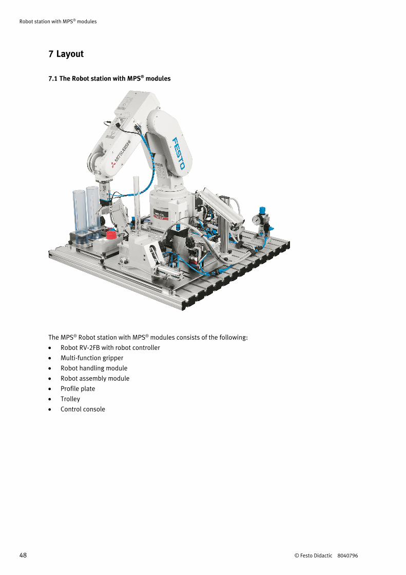
7 Layout
7.1 The Robot station with MPS® modules
The MPS® Robot station with MPS® modules consists of the following:
Robot RV-2FB with robot controller
Multi-function gripper
Robot handling module
Robot assembly module
Profile plate
Trolley
Control console
Robot station with MPS® modules
© Festo Didactic 8040796 49
7.2 Robot handling module
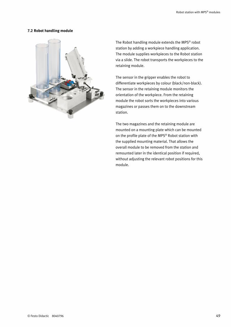
The Robot handling module extends the MPS® robot
station by adding a workpiece handling application.
The module supplies workpieces to the Robot station
via a slide. The robot transports the workpieces to the
retaining module.
The sensor in the gripper enables the robot to
differentiate workpieces by colour (black/non-black).
The sensor in the retaining module monitors the
orientation of the workpiece. From the retaining
module the robot sorts the workpieces into various
magazines or passes them on to the downstream
station.
The two magazines and the retaining module are
mounted on a mounting plate which can be mounted
on the profile plate of the MPS® Robot station with
the supplied mounting material. That allows the
overall module to be removed from the station and
remounted later in the identical position if required,
without adjusting the relevant robot positions for this
module.
Robot station with MPS® modules
50 © Festo Didactic 8040796
7.3 Robot assembly module
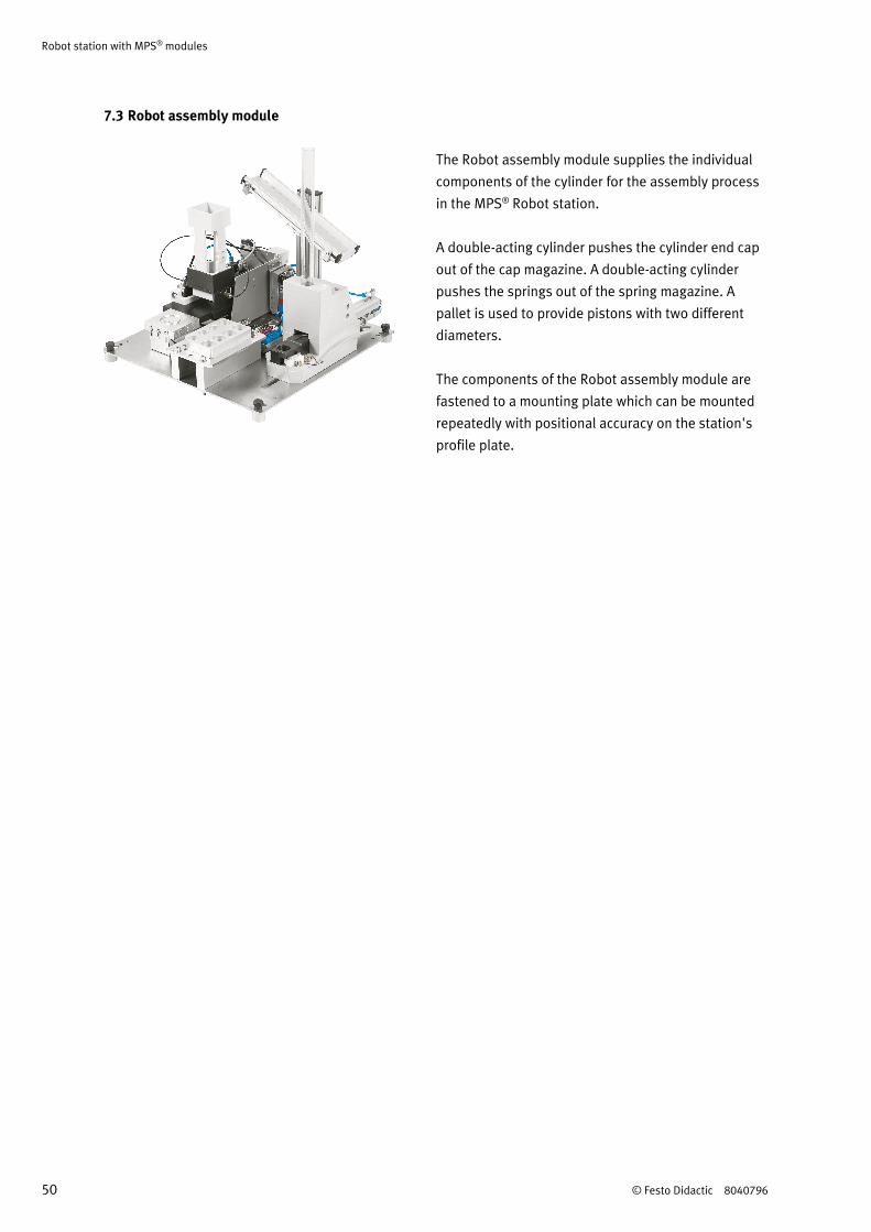
The Robot assembly module supplies the individual
components of the cylinder for the assembly process
in the MPS® Robot station.
A double-acting cylinder pushes the cylinder end cap
out of the cap magazine. A double-acting cylinder
pushes the springs out of the spring magazine. A
pallet is used to provide pistons with two different
diameters.
The components of the Robot assembly module are
fastened to a mounting plate which can be mounted
repeatedly with positional accuracy on the station's
profile plate.
Robot station with MPS® modules
© Festo Didactic 8040796 51
8 Function
Workpieces are transported by means of a slide on the retaining device. The robot fetches the workpieces
from the retaining device with the help of a pneumatic gripper. The workpieces are deposited on the
assembly retainer.
An optical sensor is fitted to the gripper jaw. This sensor differentiates between black and non-black bodies.
The robot establishes the orientation of the body and places it in the correct orientation in the assembly
position of the Assembly retainer module.
Depending on the colour of the body the robot takes a piston from the pallet and inserts it into the body. For
red and metallic bodies black pistons are used. For black bodies metallic pistons are used. Afterwards the
piston spring is inserted.
The cap is picked up at the Cap magazine module. The robot establishes the orientation of the cap and
places it in the correct orientation on the body.
The finished pneumatic cylinder is placed on a slide.
Robot station with MPS® modules
52 © Festo Didactic 8040796
9 Sequence description
Start-up prerequisites
Workpiece cylinder body in the retainer
Spring magazine is filled, no spring at transfer position
Cap magazine is filled, no cap at transfer position
Pallet is filled with pistons
Initial position
Robot is in initial position
Gripper is open
Ejecting cylinder cap magazine retracted
Ejecting cylinder spring magazine retracted
Note
Do not insert the workpiece manually on the retainer. Use the slide for feeding.
Sequence
1. With PLC: A cap and a spring are pushed out if the START pushbutton is actuated.
2. If a workpiece “body” is detected in the retainer and the START pushbutton at the robot controller is
actuated the body is picked up by the robot.
3. The body is transported to the Assembly retainer module and placed at the “change gripper” position.
4. The colour of the body is determined.
5. The body is picked up and the orientation is checked.
Sequence for a black workpiece
6. The body is placed in the correct orientation in the “assembly” position.
7. A metallic piston is picked up at the pallet. The piston is inserted in the body.
8. Without PLC: The robot controller actuates the spring magazine.
9. The robot checks whether a spring is available. If it is, the spring is picked up and placed on the piston.
10. Without PLC: The robot controller actuates the cap magazine.
11. The robot checks whether a cap is available. If it is, the cap is picked up and placed on the bolt of the
Assembly retainer module. The orientation of the cap is checked.
12. The cap is placed in the correct orientation on the body. The cap is fixed by means of rotation.
13. The finished pneumatic cylinder is placed on the slide.
Robot station with MPS® modules
© Festo Didactic 8040796 53
Sequence for red/silver workpieces
14. The body is placed in the correct orientation in the “assembly” position.
15. A black piston is picked up at the pallet. The piston is inserted in the body.
16. Without PLC: The robot controller actuates the spring magazine.
17. The robot checks whether a spring is available. If it is, the spring is picked up and placed on the piston.
18. Without PLC: The robot controller actuates the cap magazine.
19. The robot checks whether a cap is available. If it is, the cap is picked up and placed on the bolt of the
Assembly retainer module. The orientation of the cap is checked.
20. The cap is placed in the correct orientation on the body. The cap is fixed by means of rotation.
21. The finished pneumatic cylinder is placed on the slide.
Robot station with MPS® modules
54 © Festo Didactic 8040796
10 Commissioning
MPS stations are generally shipped:
Fully assembled
Individually adjusted and ready for use
Pre-commissioned
Tested
Note
When stations are combined, the mechanical setup as well as sensor positions and settings may
have to be changed.
Commissioning is normally limited to visual inspection in order to ensure correct tubing connections, wiring
and operating voltage supply.
All components, tubing connections and cabling are clearly identified so that all of the connections can be
readily restored as required.
10.1 Workstation
The following is required to commission the MPS station:
The assembled and adjusted MPS station
The robot controller
The Teaching pendant T/B
A power supply unit 24 V DC, 4.5 A
A compressed air supply of 6 bar (600 kPa), approx. suction capacity of 50 l/min
A PC with installed Robot programming software CIROS® Studio or CIROS® Programming

Robot station with MPS® modules
© Festo Didactic 8040796 55
10.2 Cable connections
Robot controller – Robot
Connect the motor power cable (CN1) and the motor signal cable (CN2) to the controller (rear side) and
the robot.
Robot controller – T/B
Connect the cable of the T/B to the T/B connector at the front side of the controller.
Robot station with MPS® modules
56 © Festo Didactic 8040796
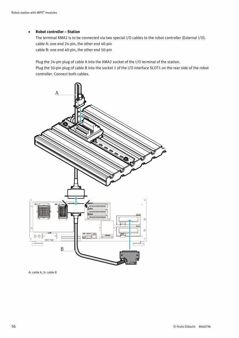
Robot controller – Station
The terminal XMA2 is to be connected via two special I/O cables to the robot controller (External I/O).
cable A: one end 24-pin, the other end 40-pin
cable B: one end 40-pin, the other end 50-pin
Plug the 24-pin plug of cable A into the XMA2 socket of the I/O terminal of the station.
Plug the 50-pin plug of cable B into the socket 1 of the I/O interface SLOT1 on the rear side of the robot
controller. Connect both cables.
A: cable A, b: cable B
Robot station with MPS® modules
© Festo Didactic 8040796 57
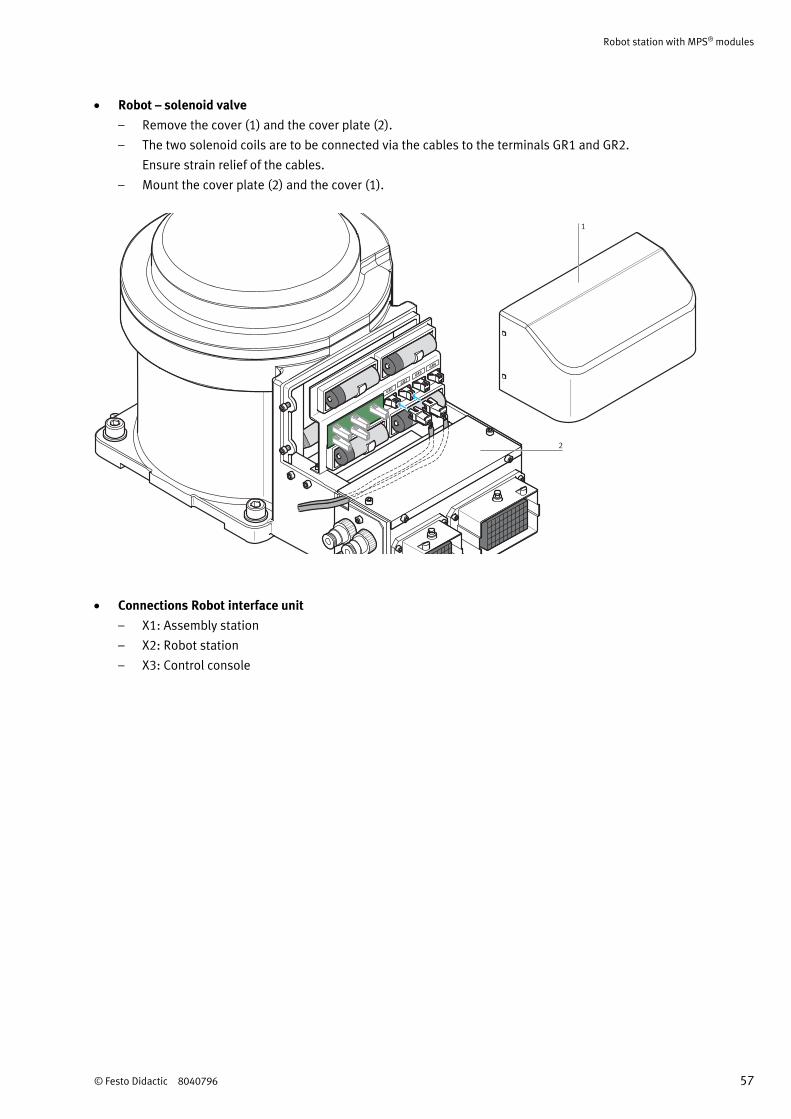
Robot – solenoid valve
– Remove the cover (1) and the cover plate (2).
– The two solenoid coils are to be connected via the cables to the terminals GR1 and GR2.
Ensure strain relief of the cables.
– Mount the cover plate (2) and the cover (1).
GR1
GR2
GR3
GR4
1
2
Connections Robot interface unit
– X1: Assembly station
– X2: Robot station
– X3: Control console
Robot station with MPS® modules
58 © Festo Didactic 8040796
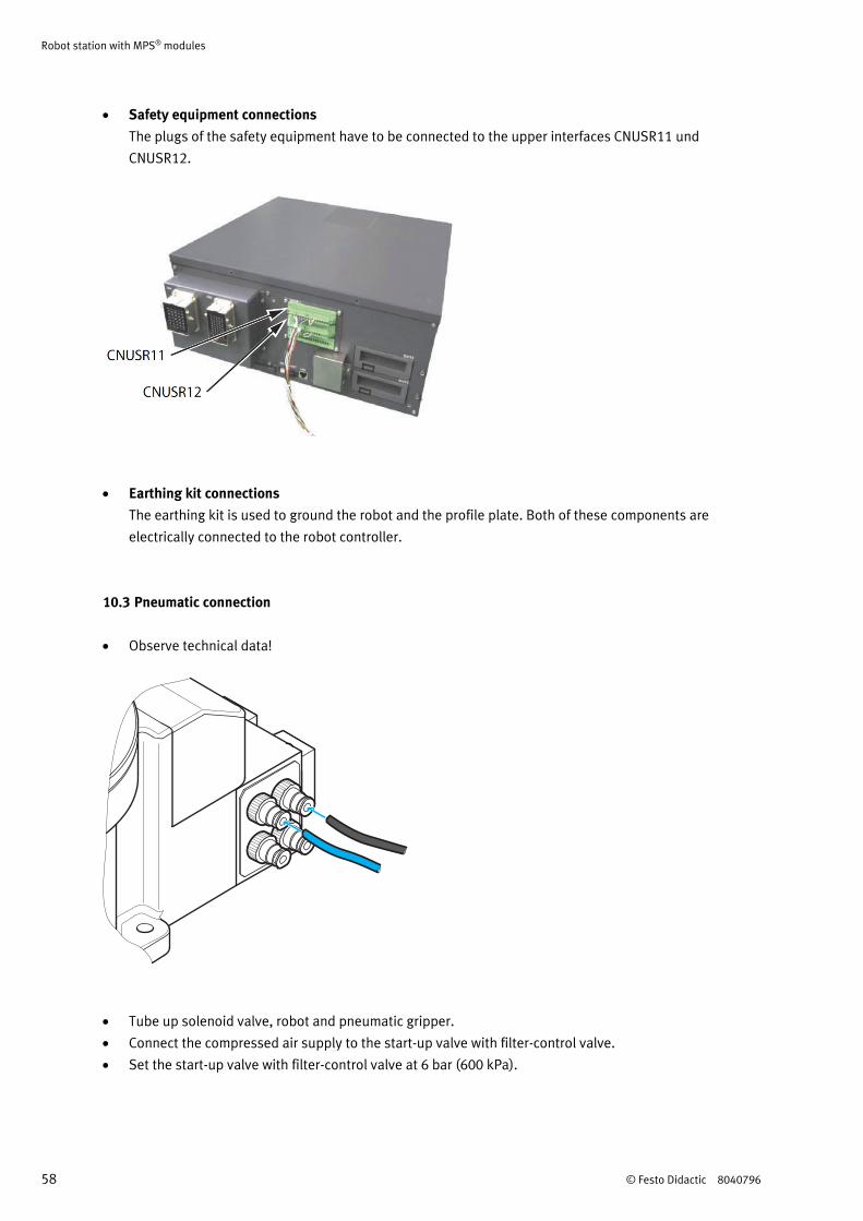
Safety equipment connections
The plugs of the safety equipment have to be connected to the upper interfaces CNUSR11 und
CNUSR12.
Earthing kit connections
The earthing kit is used to ground the robot and the profile plate. Both of these components are
electrically connected to the robot controller.
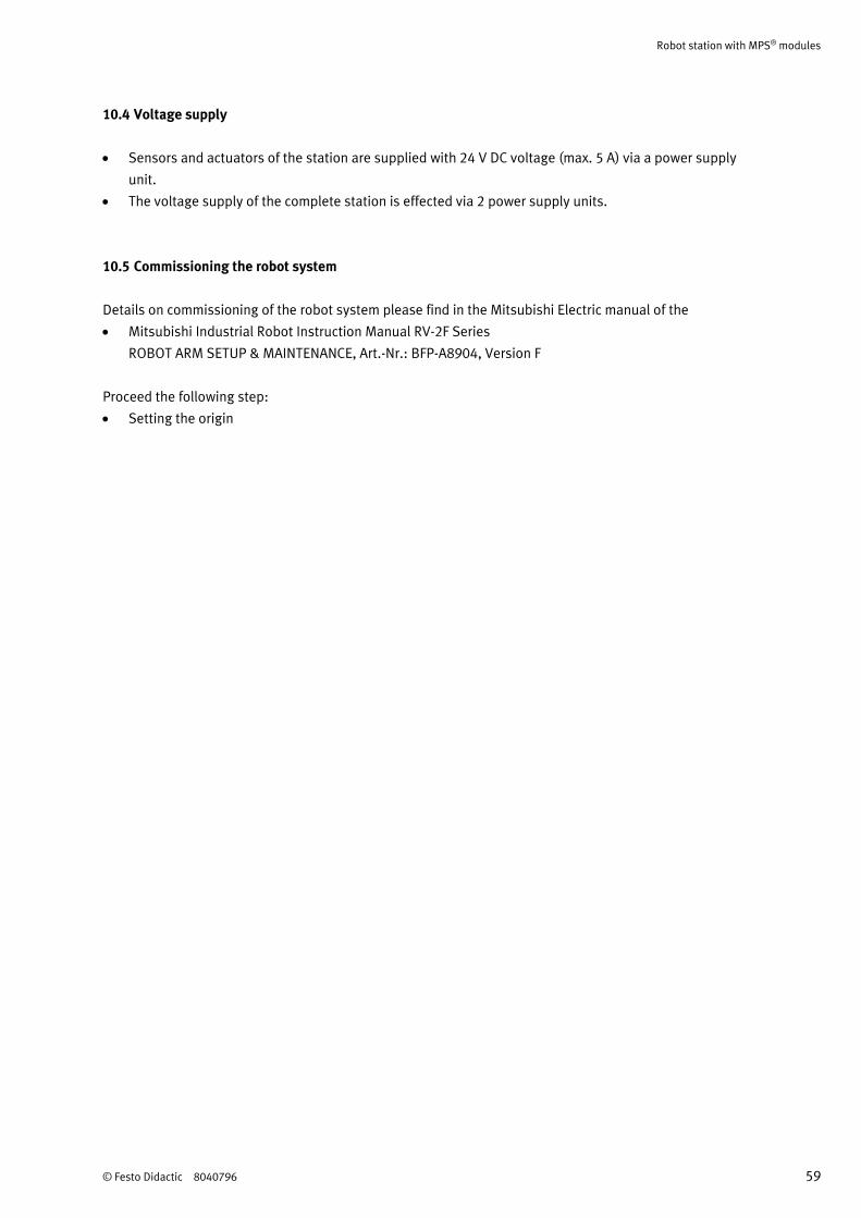
10.3 Pneumatic connection
Observe technical data!
Tube up solenoid valve, robot and pneumatic gripper.
Connect the compressed air supply to the start-up valve with filter-control valve.
Set the start-up valve with filter-control valve at 6 bar (600 kPa).
Robot station with MPS® modules
© Festo Didactic 8040796 59
10.4 Voltage supply
Sensors and actuators of the station are supplied with 24 V DC voltage (max. 5 A) via a power supply
unit.
The voltage supply of the complete station is effected via 2 power supply units.
10.5 Commissioning the robot system
Details on commissioning of the robot system please find in the Mitsubishi Electric manual of the
Mitsubishi Industrial Robot Instruction Manual RV-2F Series
ROBOT ARM SETUP & MAINTENANCE, Art.-Nr.: BFP-A8904, Version F
Proceed the following step:
Setting the origin
Robot station with MPS® modules
60 © Festo Didactic 8040796
10.6 Loading the robot program
Robot controller: CR750-D
Programming software: CIROS® Studio or CIROS® Programming
1. Connect PC and robot controller using the programming cable
2. Switch on the robot controller
3. Switch on the power supply unit
4. Switch on the compressed air supply
5. Release the EMERGENCY-STOP switch
6. Start the robot programming software
7. 5 different programs are available::
– 3.mb5: with orientation
– 4.mb5: without orientation
– 5.mb5: without orientation, without position variables
– 6.mb5: without orientation, position variables and subroutines
– 12.mb5: Assembly with robot
Select a program and load the file.
8. Turn the MODE switch at the robot controller to position AUTO.
9. Download the program and the position list to the robot controller.
10.7 Teaching positions
For teaching the positions proceed as follows:
1. Switch on the robot controller.
2. Release the EMERGENCY-STOP switch
3. Acknowledge errors by actuating the RESET pushbutton at the controller or by actuating the RESET
pushbutton at the T/B.
4. Turn the MODE switch at the robot controller to position TEACH.
5. Turn the changeover switch at the T/B in the ENABLE position.
6. Actuation of the MENU pushbutton displays the menu start screen.
Select 1) TEACH by actuating the INP/EXE pushbutton.
7. Enter the number of the program (3, 4, 5, or 6). Actuate the INP/EXE pushbutton.
8. Actuate the POS pushbutton. Select a specific position by actuating the +/FORWD or –/BACKWD
pushbuttons.
Select a position P1, P2, P3, P4, P5, and P99.
9. Reduce robot arm speed by actuating the –/BACKWD pushbutton
10. Press the Deadman switch and the STEP/MOVE pushbutton: When the servo motors are switched ON
actuate the INP/EXE pushbutton: the robot arm moves to the selected position.
Be careful and avoid collisions!
11. Check the position. If the position is ok, go to step 8 and check the next position. If the position is not
correct proceed with step 12.
Robot station with MPS® modules
© Festo Didactic 8040796 61
12. Press the Deadman switch at the rear side of the T/B.
13. Select a coordinate system, e.g. XYZ.
14. Actuate the STEP/MOVE pushbutton and move the robot via actuation of the
–X, +X, –Y, +Y, –Z,+Z, –A, +A, –B, and +B pushbuttons.
15. When the correct position is approached, press the ADD pushbutton twice. The actual position is
transferred to the position list.
16. Return to step 8. Please check the next position.
Note
Actuating the HAND and –C pushbuttons or the HAND and +C pushbuttons respectively closes or
opens the gripper.
10.7.1 Jog-operation mode
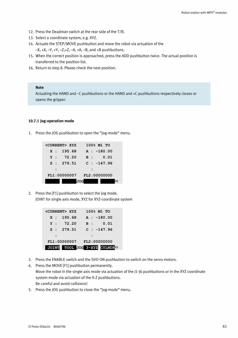
1. Press the JOG pushbutton to open the “jog-mode“ menu.
<CURRENT> XYZ 100% M1 TO
X : 195.68 A : -180.00
Y : 72.20 B : 0.01
Z : 279.51 C : -147.96
: :
FL1:00000007 FL2:00000000
ADD.AX WORK JOG CLOSE
2. Press the [F1] pushbutton to select the jog mode.
JOINT for single axis mode, XYZ for XYZ-coordinate system
<CURRENT> XYZ 100% M1 TO
X : 195.68 A : -180.00
Y : 72.20 B : 0.01
Z : 279.51 C : -147.96
: :
FL1:00000007 FL2:00000000
JOINT TOOL JOG 3-XYZ CYLNDR
3. Press the ENABLE switch and the SVO ON pushbutton to switch on the servo motors.
4. Press the MOVE [F1] pushbutton permanently.
Move the robot in the single axis mode via actuation of the J1-J6 pushbuttons or in the XYZ coordinate
system mode via actuation of the X-Z pushbuttons.
Be careful and avoid collisions!
5. Press the JOG pushbutton to close the “jog-mode“ menu.
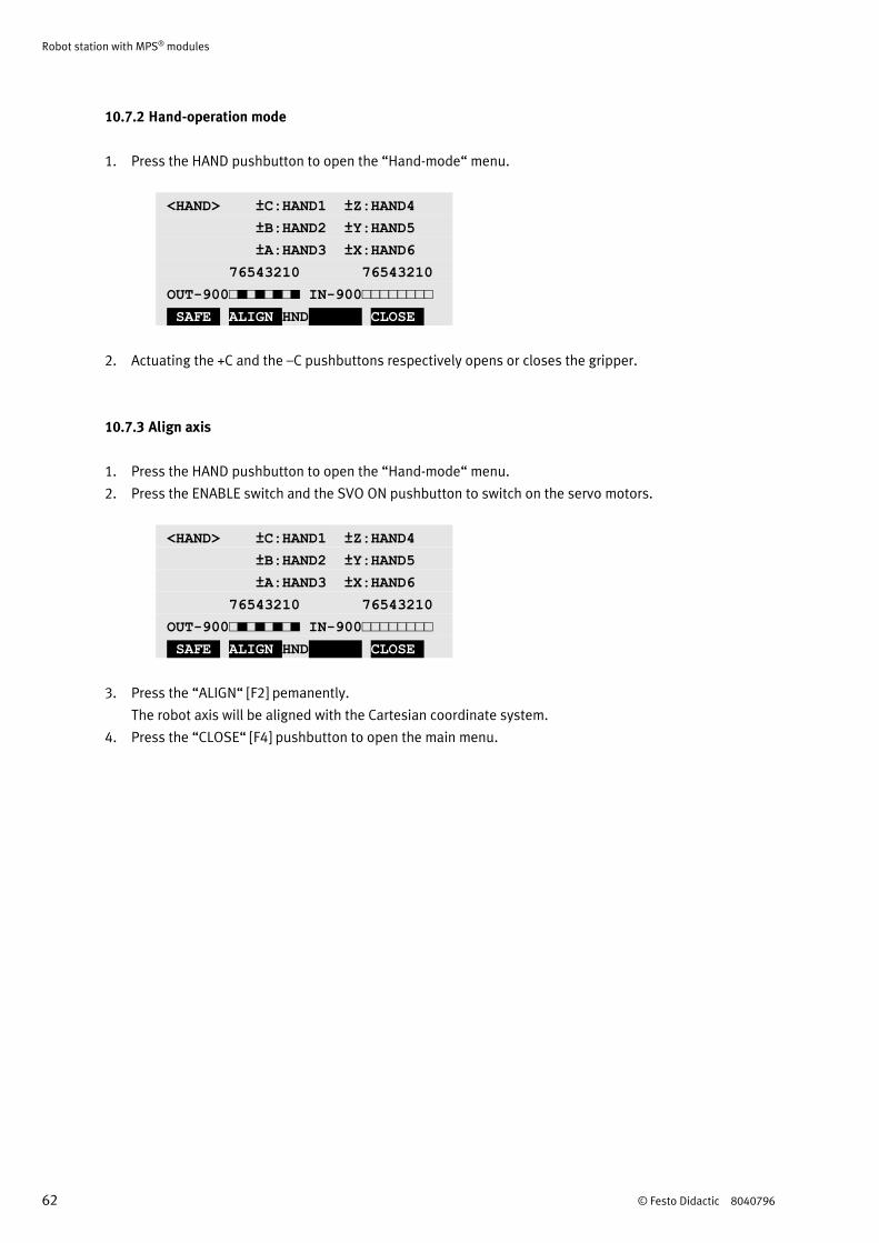
Robot station with MPS® modules
62 © Festo Didactic 8040796
10.7.2 Hand-operation mode
1. Press the HAND pushbutton to open the “Hand-mode“ menu.
<HAND> ±C:HAND1 ±Z:HAND4
±B:HAND2 ±Y:HAND5
±A:HAND3 ±X:HAND6
76543210 76543210
OUT-900□■□■□■□■ IN-900□□□□□□□□
SAFE ALIGN HND CLOSE
2. Actuating the +C and the –C pushbuttons respectively opens or closes the gripper.
10.7.3 Align axis
1. Press the HAND pushbutton to open the “Hand-mode“ menu.
2. Press the ENABLE switch and the SVO ON pushbutton to switch on the servo motors.
<HAND> ±C:HAND1 ±Z:HAND4
±B:HAND2 ±Y:HAND5
±A:HAND3 ±X:HAND6
76543210 76543210
OUT-900□■□■□■□■ IN-900□□□□□□□□
SAFE ALIGN HND CLOSE
3. Press the “ALIGN“ [F2] pemanently.
The robot axis will be aligned with the Cartesian coordinate system.
4. Press the “CLOSE“ [F4] pushbutton to open the main menu.
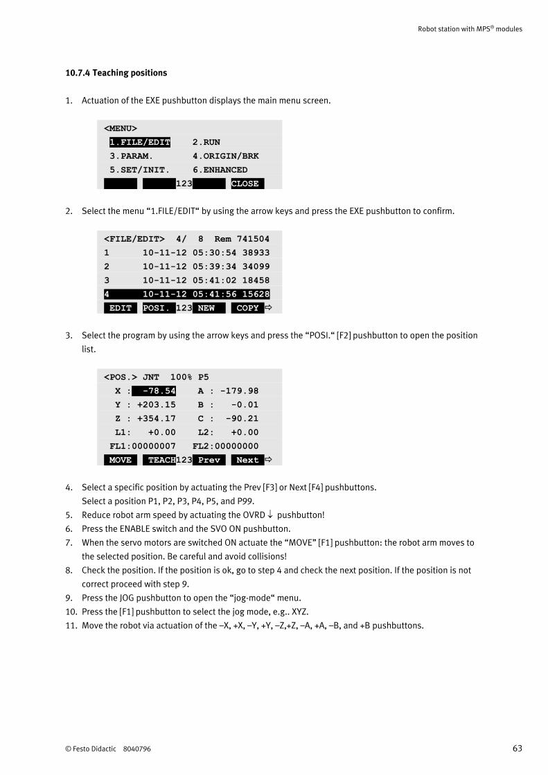
Robot station with MPS® modules
© Festo Didactic 8040796 63
10.7.4 Teaching positions
1. Actuation of the EXE pushbutton displays the main menu screen.
<MENU>
1.FILE/EDIT 2.RUN
3.PARAM. 4.ORIGIN/BRK
5.SET/INIT. 6.ENHANCED
123 CLOSE
2. Select the menu “1.FILE/EDIT“ by using the arrow keys and press the EXE pushbutton to confirm.
<FILE/EDIT> 4/ 8 Rem 741504
1 10-11-12 05:30:54 38933
2 10-11-12 05:39:34 34099
3 10-11-12 05:41:02 18458
4 10-11-12 05:41:56 15628
EDIT POSI. 123 NEW COPY
3. Select the program by using the arrow keys and press the “POSI.“ [F2] pushbutton to open the position
list.
<POS.> JNT 100% P5
X : -78.54 A : -179.98
Y : +203.15 B : -0.01
Z : +354.17 C : -90.21
L1: +0.00 L2: +0.00
FL1:00000007 FL2:00000000
MOVE TEACH123 Prev Next
4. Select a specific position by actuating the Prev [F3] or Next [F4] pushbuttons.
Select a position P1, P2, P3, P4, P5, and P99.
5. Reduce robot arm speed by actuating the OVRD pushbutton!
6. Press the ENABLE switch and the SVO ON pushbutton.
7. When the servo motors are switched ON actuate the “MOVE” [F1] pushbutton: the robot arm moves to
the selected position. Be careful and avoid collisions!
8. Check the position. If the position is ok, go to step 4 and check the next position. If the position is not
correct proceed with step 9.
9. Press the JOG pushbutton to open the “jog-mode“ menu.
10. Press the [F1] pushbutton to select the jog mode, e.g.. XYZ.
11. Move the robot via actuation of the –X, +X, –Y, +Y, –Z,+Z, –A, +A, –B, and +B pushbuttons.
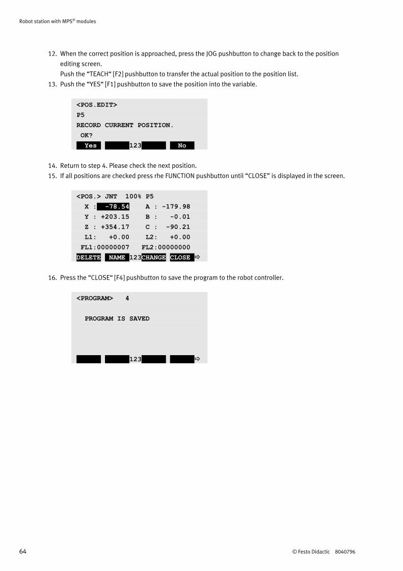
Robot station with MPS® modules
64 © Festo Didactic 8040796
12. When the correct position is approached, press the JOG pushbutton to change back to the position
editing screen.
Push the “TEACH“ [F2] pushbutton to transfer the actual position to the position list.
13. Push the “YES“ [F1] pushbutton to save the position into the variable.
<POS.EDIT>
P5
RECORD CURRENT POSITION.
OK?
Yes 123 No
14. Return to step 4. Please check the next position.
15. If all positions are checked press rhe FUNCTION pushbutton until “CLOSE” is displayed in the screen.
<POS.> JNT 100% P5
X : -78.54 A : -179.98
Y : +203.15 B : -0.01
Z : +354.17 C : -90.21
L1: +0.00 L2: +0.00
FL1:00000007 FL2:00000000
DELETE NAME 123CHANGE CLOSE
16. Press the “CLOSE“ [F4] pushbutton to save the program to the robot controller.
<PROGRAM> 4
PROGRAM IS SAVED
123
Robot station with MPS® modules
© Festo Didactic 8040796 65
10.8 Starting the sequence
1. Check the voltage supply and compressed air supply.
2. Remove the workpieces at the transfer points of modules or stations prior to manual reset.
3. The robot is in initial position.
4. Feed a workpiece via the slide to the retainer module.
5. Start the sequence of the Robot station:
Turn the changeover switch at the T/B in the DISABLE position.
Turn the MODE switch of the robot controller to position AUTO.
Select the program menu display by pressing the CHANG.DISP pushbutton.
Using the UP and DOWN pushbuttons select the correct program number.
Switch on the servo power by actuating the SVO ON pushbutton.
Actuate the START pushbutton of the robot controller.
Notes
• The sequence can be stopped at any time by pressing the EMERGENCY-STOP pushbutton
or the STOP pushbutton.
• In the case of a combination of stations the following applies:
The individual stations are reset against the material flow.
• If there aren’t any springs in the spring magazine, the SPRING MAG. EMPTY indicator lamp
lights up. Load springs in this case.
• If there aren’t any caps in the cap magazine, the CAP MAG. EMPTY indicator lamp
lights up. Load caps in this case.
Robot station with MPS® modules
66 © Festo Didactic 8040796
11 Maintenance and care
The MPS® stations are largely maintenance-free. The following components should be cleaned at regular
intervals with a soft, lint-free cloth or brush:
The lenses on the optical sensors, the fibre optics and the reflectors
The active surface of the proximity switch
The entire station
Notes
• Do not use aggressive or abrasive cleaning agents.
• When cleaning the safety windows of the safety enclosure use only clear water.
11.1 Replacement of batteries
The batteries of the controller and the robot arm should be replaced annually. The robot arm uses a backup
battery to save the encoder position data when the power is turned off. The controller also uses a backup
battery to save the program, etc. When the battery life nears, an error message will occur. Once the alarm
occurs, all batteries in the robot arm and the controller should be replaced as soon as possible to avoid data
loss.
Notes
• Observe the information in the Mitsubishi manuals.
• Observe the assemly instructions of the safety enclosure.
12 Further information and updates
Further information and updates of the technical documentation for the MPS stations is available on the
following website:
www.festo-didactic.com > Services > MPS® The Modular Production System


Festo Didactic GmbH & Co. KG
Rechbergstraße 3
73770 Denkendorf
Germany
Internet: www.festo-didactic.com
E-mail: [email protected]


