Springer Handbooks Springer Handbook of Crystal Growth Bearbeitet von Govindhan Dhanaraj, Kullaiah Byrappa, Vishwanath Prasad, Michael Dudley 1. Auflage 2010. Buch. XXXVIII, 1818 S. ISBN 978 3 540 74182 4 Format (B x L): 19,3 x 24,2 cm Weitere Fachgebiete > Physik, Astronomie > Thermodynamik > Festkörperphysik, Kondensierte Materie schnell und portofrei erhältlich bei Die Online-Fachbuchhandlung beck-shop.de ist spezialisiert auf Fachbücher, insbesondere Recht, Steuern und Wirtschaft. Im Sortiment finden Sie alle Medien (Bücher, Zeitschriften, CDs, eBooks, etc.) aller Verlage. Ergänzt wird das Programm durch Services wie Neuerscheinungsdienst oder Zusammenstellungen von Büchern zu Sonderpreisen. Der Shop führt mehr als 8 Millionen Produkte.
Transcript
Springer Handbooks
Springer Handbook of Crystal Growth
Bearbeitet vonGovindhan Dhanaraj, Kullaiah Byrappa, Vishwanath Prasad, Michael Dudley
Weitere Fachgebiete > Physik, Astronomie > Thermodynamik > Festkörperphysik,Kondensierte Materie
schnell und portofrei erhältlich bei
Die Online-Fachbuchhandlung beck-shop.de ist spezialisiert auf Fachbücher, insbesondere Recht, Steuern und Wirtschaft.Im Sortiment finden Sie alle Medien (Bücher, Zeitschriften, CDs, eBooks, etc.) aller Verlage. Ergänzt wird das Programmdurch Services wie Neuerscheinungsdienst oder Zusammenstellungen von Büchern zu Sonderpreisen. Der Shop führt mehr
Generation an4. Generation and Propagationof Defects During Crystal Growth
Helmut Klapper
This chapter presents a review of the typicalgrowth defects of crystals fully grown on (planar)habit faces, i. e. of crystals grown in all kindsof solutions, in supercooled melt (mainly low-melting organics) and in the vapour phase. Toa smaller extent also growth on rounded facesfrom the melt is considered when it seemed tobe adequate to bring out analogies or discussresults in a more general context. The origins andthe typical configurations of defects developingduring growth and after growth are illustrated bya series of selected x-ray diffraction topographs(Lang technique) and, in a few cases, by opticalphotographs.
After the introduction (Sect. 4.1) the reviewstarts with the formation of inclusions (Sect. 4.2)which are the main origin of other growth de-fects such as dislocations and twins. Three kindsof inclusions are treated: foreign particles, liquidinclusions (of nutrient solution) and solute pre-cipitates. Particular attention is directed to theregeneration of seed crystals into a fully facettedshape (capping), and inclusion formation due toimproper hydrodynamics in the solution (especiallyfor KDP).
Section 4.3 deals shortly with striations (treatedin more detail in another Chapter) and morecomprehensive with the different kinds of crystalregions grown on different growth faces: growthsectors, vicinal sectors, facet sectors. These regionsare usually differently perfect and possess moreor less different physical properties, and theboundaries between them frequently are faultedinternal surfaces of the crystal. Two subsectionstreat the optical anomalies of growth and vicinalsectors and the determination of the relativegrowth rates of neighboured growth faces fromthe orientation of their common sector boundary.
In Sect. 4.4 distinction is made between dis-locations connected to and propagating with thegrowth interface (growth dislocations), and dis-
locations generated behind the growth front byplastic glide due to stress relaxation. The mainsources of both types of dislocations are inclu-sions. In crystals grown on planar faces, growthdislocations are usually straight-lined and follow(frequently noncrystallographic) preferred direc-tions depending on the Burgers vector, on thegrowth direction and the elastic constants of thecrystal. These directions are explained by a min-imum of the dislocation line energy per growthlength or, equivalently, by zero force exerted bythe growth surface on the dislocation. Calculationsbased on anisotropic linear elasticity of a con-tinuum confirm this approach. The influence ofthe discrete lattice structure and core energy ondislocation directions is discussed. Further subsec-tions deal with the Burgers vector determinationby preferred directions, with the post-growthmovement of grown-in dislocations, with thegeneration of post-growth dislocations, and withthe growth-promoting effect of edge dislocations.
In Sect. 4.5, Twinning, the main characteristicsof twins and their boundaries, their generation bynucleation and by inclusions, their propagationwith the growth front and their growth promotingeffect are presented. The post-growth formationof twins by phase transitions and ferroelastic(mechanical) switching is shortly outlined. Thelast Sect. 4.6 compares the perfection of crystals(KDP and ADP) slowly and rapidly grown fromsolutions, that the optical and structural qualityof rapidly grown crystals is not inferior to that ofslowly grown crystals, if particular precautions andgrowth conditions are met.
The present chapter mainly deals with growth defects incrystals fully grown on (planar) habit faces. To a smallerextent also crystals grown on rounded faces from themelt are considered when it seemed to be adequate tobring out analogies or discuss results in a more gen-eral context. Crystals grow on habit faces in solutions,in supercooled melts and in the vapour. A special fea-ture of this growth method is that there is practicallyno temperature gradient inside the crystal, provided thatfacet growth occurs freely on the whole surface of thecrystal (without contact to a container wall). This isalso the case for growth in the supercooled melt: thecrystallization heat released at the growing habit faceskeeps these on crystallization temperature – or at leastclose to it [4.1]. The absence of a temperature gradientand, thus, of thermal stress inside the crystal allows thedevelopment of defect structures according to first ther-modynamical principles and to preserve them in theiras-grown geometries, unless thermal gradients are in-troduced by improper cooling to room temperature aftergrowth. This particularly concerns dislocations in crys-tals growing in their plastic state. Dislocations are theessential elements of stress relaxation by plastic glide:they are generated, moved and multiplied by stress.Thus – in the presence of thermal stress – it makesan essential difference whether crystals are grown intheir brittle or their plastic state. From solution, crys-tals grow in the brittle or in the plastic state (dependenton the specific mechanical properties at growth temper-ature); from the melt, however, crystals always grow in
the plastic state, because each material has a more orless extended plastic zone below its melting point. Itwill be shown that growth dislocations develop the samegeometrical features in crystals grown on habit facesfrom solution in the brittle state and from supercooledmelts in the plastic state, provided thermal gradients areabsent.
In this review the generation of defects at the in-terface and the propagation with the advancing growthfront are separately considered. This is because cer-tain defects formed by a growth disturbance (e.g. byinclusions) may heal out and do not continue into thefurther growing crystal, whereas other defects (disloca-tions, twins, grain boundaries), once initiated, are forcedto proceed with the interface despite growth under op-timal conditions. These defects can only be eliminatedby growing out at the sides of the crystal, e.g., duringCzochralski pulling on interfaces which are convex to-ward the melt. Moreover, distinction is made betweendefects always connected to the interface (growth de-fects, esp. growth dislocations) and defects generated‘behind’ the growth front (post-growth defects). The lat-ter defects may be formed already during the growthrun, either by thermal stress or by precipitation. Fur-thermore, defect configurations may be preserved intheir as-grown geometry or changed after growth (e.g.,post-growth movement of dislocations).
Many experimental results and the majority ofphotographs presented in this review were obtainedby growth experiments and x-ray topographic studies
PartA
4.1
Generation and Propagation of Defects During Crystal Growth 4.2 Inclusions 3
(Lang technique) in the author’s laboratories in Aachenand Bonn. Crystals were grown from aqueous and or-ganic solutions, from supercooled melts (organics) andby Czochralski pulling (organics). The organic crys-tals were considered as low-melting model substances(melting points below 100 ◦C), chosen with the primaryaim to study the generation and propagation of growthdefects in dependence on growth methods and varyinggrowth conditions. The main characterisation method,
x-ray diffraction topography, is not treated here; thereader is referred to the reviews [4.2–5] in the liter-ature and to Chap. XXchap]Please supply the chaptertitle or number. by Dudley in this Handbook. Morespecialized x-ray topographic treatments are given fortwinned crystals [4.6] and for organic crystals [4.7].Earlier reviews on the generation and propagation ofgrowth defects were published by the author [4.8–11].
4.2 Inclusions
Two categories of inclusions are distinguished accord-ing their genetic origin [4.12, 13]: primary inclusionsare associated with the growth front, i. e. they arise dur-ing growth, whereas secondary inclusions are formedafter growth. Primary inclusions are key defects becausethey are the source of other defects (dislocations, twins)which propagate with the growth front into the furthergrowing crystal. Inclusions of both categories may formstress centres which give rise to dislocation loops orhalf-loops by plastic glide (stress relaxation). Amongprimary inclusions three kinds are distinguished:
• Foreign particles• Solvent (liquid) inclusions in crystals grown fromsolutions• Solute precipitations in crystals grown from impureor doped melts
Secondary inclusions are precipitates of solute im-purities (dopants) formed after growth in the solid stateduring slow cooling, annealing or processing of crys-tals which are grown at high temperatures. They aredue to the supersaturation of solutes at temperatures be-low the temperature at which the crystal was grown.These solutes precipitate if their diffusion mobility issufficiently high and not frozen-in (as is usually thecase at room temperature). In the same way vacan-cies and self-interstitials may condense into dislocationloops and stacking faults, e.g. during processing sili-con crystals for electronic applications (swirl defects,e.g. [4.14]).
Here we treat only primary inclusions. A very de-tailed theoretical and experimental treatment of thecapture of inclusions during crystal growth is presentedby Chernov and Temkin [4.15]. A similar study withparticular consideration of crystallization pressure is re-ported by Khaimov-Mal’kov [4.16].
4.2.1 Foreign Particles
Foreign particles pre-existing in the nutrient (solution,melt) increase the risk of (heterogeneous) nucleation.Their incorporation into the growing crystal, however,is often considered as not very critical due to thecrystallisation pressure [4.16] (disjoining force afterChernov and Temkin [4.15]) which repulses foreignparticles from the growth interface. Nevertheless, par-ticles coming into contact with the growth face maybe incorporated, depending on the size and chem-ical/physical nature of the particles and on growthconditions such as stirring, growth rate, supersatura-tion [4.15]. For example, potassium alum crystals canbe grown inclusion-free (as assessed by optical inspec-tion and x-ray topography) from old (i. e. repeatedlyused) unfiltered aqueous solutions containing manyfloating dust particles, provided that growth condi-tions (temperature control, stirring) are stable enoughto avoid the formation of liquid inclusions (see below).On the other hand in crystals of benzil grown in old(repeatedly filled up) supercooled melts (Tm = 96 ◦C),flocks of solid decomposition products floating in themelt are quite readily incorporated (unpublished obser-vation by the author). In contrast to the solution growthof potassium alum, such benzil melts were not stirred,but thermal convection occurred due to the release ofcrystallization heat at the crystal surface [4.1]. In thelatter case the incorporation seems to be favoured bythe higher viscosity and the lower agitation of the nutri-ent phase, and probably also by the chemical similarity(carbon) of the particles to the growing crystal.
Foreign solid inclusions are very common in min-erals. In laboratory and industrial crystal growth theyusually play a minor role because they are easilyavoided by filtering of the nutrient before growth. Ifsolid inclusions appear during the growth run, e.g.,
PartA
4.2
4 Part A Solid Mechanics Topics
as abrasives of the stirring device, continuous filter-ing is advised. This has been demonstrated by Zaitsevaet al. [4.17] for the rapid growth of huge KDP andDKDPdef]Please define this abbreviation at first use.crystals with linear sizes up to 55 cm: continuous filter-ing during the whole growth run considerably increasedthe optical quality and laser damage threshold of thesecrystals.
The intentional incorporation of particle inclusionsfor the study of the generation of dislocations is reportedin Sect. 4.4.2. The intentional inclusion of oil drops dur-ing crystallization from solutions was studied by Kliiaand Sokolova [4.18].
4.2.2 Solvent Inclusions
Solvent inclusions are very common in crystals grownby all variants of solution growth (aqueous and organicsolvents, flux). Two origins are distinguished.
Facetting (Capping) of Rounded SurfacesIn general crystals grow from solutions with planarfaces (habit faces), whereby faces with low surface en-ergy grow slowly and determine the final morphologyof the crystal (Wulff theorem [4.19]). If surfaces arerounded, (e.g., of the seed crystal or after redissolution),during first growth, facets of habit faces and (betweenthem) terraces of these faces are formed. The facetsbecome larger and the terraced regions grow out un-til a single edge between the two habit faces engagedis formed, as shown in Fig. 4.1 (Theorem of Her-ring [4.20–23], see also growth on spheres [4.24][4.25,p.130]). The healed-out regions often have the shape ofcaps (capping region). The growth on terraced surfacesfavours the entrapment of solvent inclusions which maylead in extreme cases to a spongy structure of the cap-ping region. This usually happens during first growth onseed crystals which were rounded during a final etching
C C
Fig. 4.1 Faceting and capping on rounded crystal surfaces.The shaded regions of terraced growth favour the entrap-ment of liquid inclusions. They grow out and finally formthe growth-sector boundary between the main habit faces
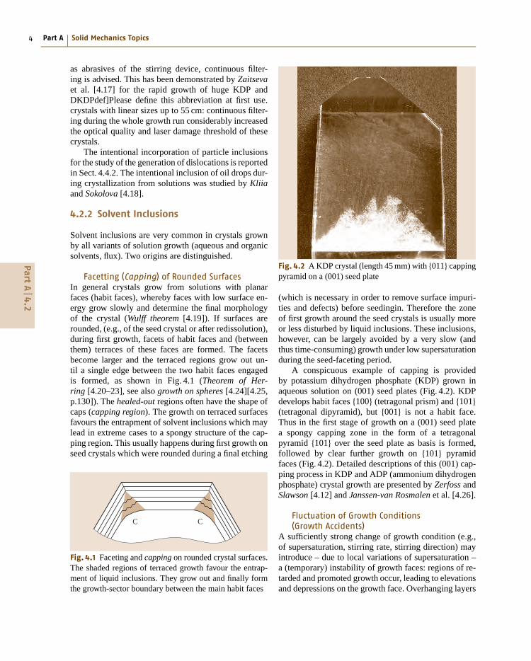
Fig. 4.2 A KDP crystal (length 45 mm) with {011} cappingpyramid on a (001) seed plate
(which is necessary in order to remove surface impuri-ties and defects) before seedingin. Therefore the zoneof first growth around the seed crystals is usually moreor less disturbed by liquid inclusions. These inclusions,however, can be largely avoided by a very slow (andthus time-consuming) growth under low supersaturationduring the seed-faceting period.
A conspicuous example of capping is providedby potassium dihydrogen phosphate (KDP) grown inaqueous solution on (001) seed plates (Fig. 4.2). KDPdevelops habit faces {100} (tetragonal prism) and {101}(tetragonal dipyramid), but {001} is not a habit face.Thus in the first stage of growth on a (001) seed platea spongy capping zone in the form of a tetragonalpyramid {101} over the seed plate as basis is formed,followed by clear further growth on {101} pyramidfaces (Fig. 4.2). Detailed descriptions of this (001) cap-ping process in KDP and ADP (ammonium dihydrogenphosphate) crystal growth are presented by Zerfoss andSlawson [4.12] and Janssen-van Rosmalen et al. [4.26].
Fluctuation of Growth Conditions(Growth Accidents)
A sufficiently strong change of growth condition (e.g.,of supersaturation, stirring rate, stirring direction) mayintroduce – due to local variations of supersaturation –a (temporary) instability of growth faces: regions of re-tarded and promoted growth occur, leading to elevationsand depressions on the growth face. Overhanging layers
PartA
4.2
Generation and Propagation of Defects During Crystal Growth 4.3 Striations and Growth Sectors 9
and, thus, to changes of the impurity incorporation.As a rule, they affect the whole growth front andthus form inhomogeneity layers parallel to the in-terface. The term striations is usually applied whenthe impurity layers appear in a (quasi)-periodic se-quence (Fig. 4.8a). If there are isolated layers, dueto sporadic changes of growth conditions, often theterm growth bands is used. In mineralogy, the no-tation growth zoning is common. In crystals grownunder rotation, strictly periodic rotational striations,correlated with the rotation rate, may occur. They aredue to a nonuniform radial temperature distributionaround the rotation axis, leading to slight changes ofgrowth conditions (even with remelting) within a rota-tion period.
The impurities may be contaminants of the solu-tion or of the melt, or incorporated solvent components.Striations are also formed by dopants intentionally
a)
b)
S
S: Seed crystal
Growth sector boundary
Growth sector boundary
Growth sector
Growth sector
Seed crystal
Growth striations
Growth face
n3
n4
n5
n6
n1
n2
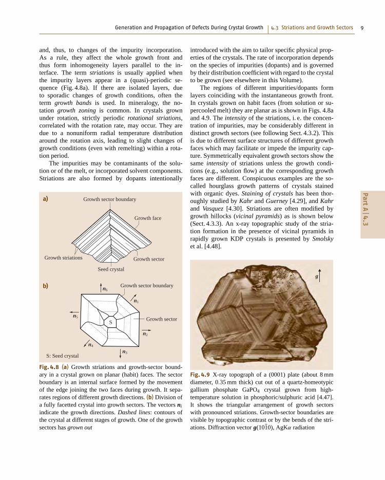
Fig. 4.8 (a) Growth striations and growth-sector bound-ary in a crystal grown on planar (habit) faces. The sectorboundary is an internal surface formed by the movementof the edge joining the two faces during growth. It sepa-rates regions of different growth directions. (b) Division ofa fully facetted crystal into growth sectors. The vectors ni
indicate the growth directions. Dashed lines: contours ofthe crystal at different stages of growth. One of the growthsectors has grown out
introduced with the aim to tailor specific physical prop-erties of the crystals. The rate of incorporation dependson the species of impurities (dopants) and is governedby their distribution coefficient with regard to the crystalto be grown (see elsewhere in this Volume).
The regions of different impurities/dopants formlayers coinciding with the instantaneous growth front.In crystals grown on habit faces (from solution or su-percooled melt) they are planar as is shown in Figs. 4.8aand 4.9. The intensity of the striations, i. e. the concen-tration of impurities, may be considerably different indistinct growth sectors (see following Sect. 4.3.2). Thisis due to different surface structures of different growthfaces which may facilitate or impede the impurity cap-ture. Symmetrically equivalent growth sectors show thesame intensity of striations unless the growth condi-tions (e.g., solution flow) at the corresponding growthfaces are different. Conspicuous examples are the so-called hourglass growth patterns of crystals stainedwith organic dyes. Staining of crystals has been thor-oughly studied by Kahr and Guerney [4.29], and Kahrand Vasquez [4.30]. Striations are often modified bygrowth hillocks (vicinal pyramids) as is shown below(Sect. 4.3.3). An x-ray topographic study of the stria-tion formation in the presence of vicinal pyramids inrapidly grown KDP crystals is presented by Smolskyet al. [4.48].
g
Fig. 4.9 X-ray topograph of a (0001) plate (about 8 mmdiameter, 0.35 mm thick) cut out of a quartz-homeotypicgallium phosphate GaPO4 crystal grown from high-temperature solution in phosphoric/sulphuric acid [4.47].It shows the triangular arrangement of growth sectorswith pronounced striations. Growth-sector boundaries arevisible by topographic contrast or by the bends of the stri-ations. Diffraction vector g(101̄0), AgKα radiation
PartA
4.3
10 Part A Solid Mechanics Topics
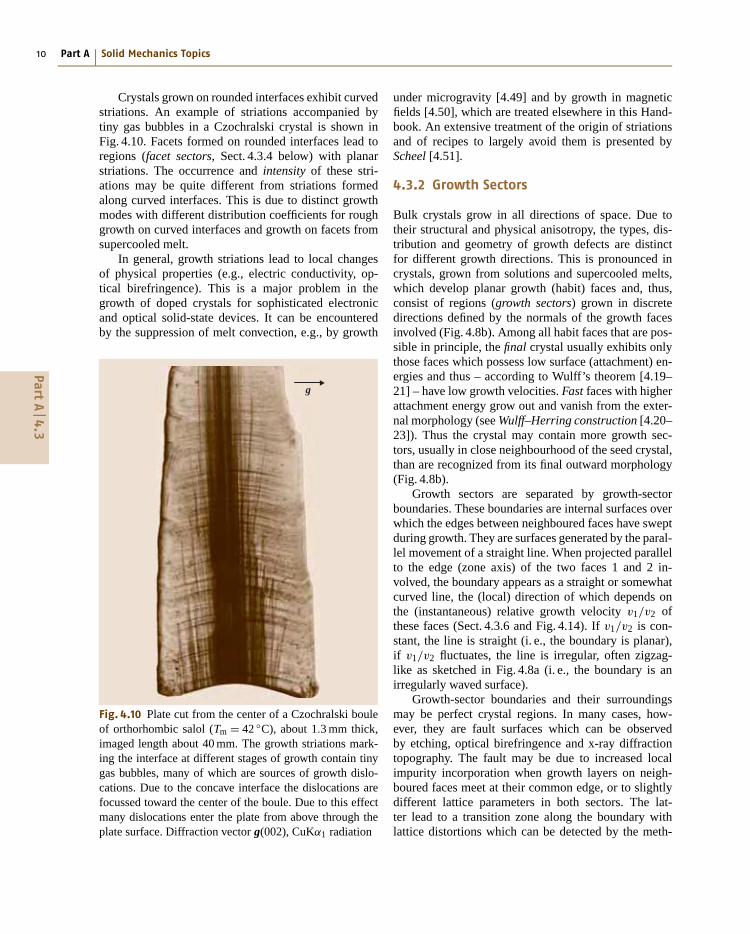
Crystals grown on rounded interfaces exhibit curvedstriations. An example of striations accompanied bytiny gas bubbles in a Czochralski crystal is shown inFig. 4.10. Facets formed on rounded interfaces lead toregions (facet sectors, Sect. 4.3.4 below) with planarstriations. The occurrence and intensity of these stri-ations may be quite different from striations formedalong curved interfaces. This is due to distinct growthmodes with different distribution coefficients for roughgrowth on curved interfaces and growth on facets fromsupercooled melt.
In general, growth striations lead to local changesof physical properties (e.g., electric conductivity, op-tical birefringence). This is a major problem in thegrowth of doped crystals for sophisticated electronicand optical solid-state devices. It can be encounteredby the suppression of melt convection, e.g., by growth
g
Fig. 4.10 Plate cut from the center of a Czochralski bouleof orthorhombic salol (Tm = 42 ◦C), about 1.3 mm thick,imaged length about 40 mm. The growth striations mark-ing the interface at different stages of growth contain tinygas bubbles, many of which are sources of growth dislo-cations. Due to the concave interface the dislocations arefocussed toward the center of the boule. Due to this effectmany dislocations enter the plate from above through theplate surface. Diffraction vector g(002), CuKα1 radiation
under microgravity [4.49] and by growth in magneticfields [4.50], which are treated elsewhere in this Hand-book. An extensive treatment of the origin of striationsand of recipes to largely avoid them is presented byScheel [4.51].
4.3.2 Growth Sectors
Bulk crystals grow in all directions of space. Due totheir structural and physical anisotropy, the types, dis-tribution and geometry of growth defects are distinctfor different growth directions. This is pronounced incrystals, grown from solutions and supercooled melts,which develop planar growth (habit) faces and, thus,consist of regions (growth sectors) grown in discretedirections defined by the normals of the growth facesinvolved (Fig. 4.8b). Among all habit faces that are pos-sible in principle, the final crystal usually exhibits onlythose faces which possess low surface (attachment) en-ergies and thus – according to Wulff’s theorem [4.19–21] – have low growth velocities. Fast faces with higherattachment energy grow out and vanish from the exter-nal morphology (see Wulff–Herring construction [4.20–23]). Thus the crystal may contain more growth sec-tors, usually in close neighbourhood of the seed crystal,than are recognized from its final outward morphology(Fig. 4.8b).
Growth sectors are separated by growth-sectorboundaries. These boundaries are internal surfaces overwhich the edges between neighboured faces have sweptduring growth. They are surfaces generated by the paral-lel movement of a straight line. When projected parallelto the edge (zone axis) of the two faces 1 and 2 in-volved, the boundary appears as a straight or somewhatcurved line, the (local) direction of which depends onthe (instantaneous) relative growth velocity v1/v2 ofthese faces (Sect. 4.3.6 and Fig. 4.14). If v1/v2 is con-stant, the line is straight (i. e., the boundary is planar),if v1/v2 fluctuates, the line is irregular, often zigzag-like as sketched in Fig. 4.8a (i. e., the boundary is anirregularly waved surface).
Growth-sector boundaries and their surroundingsmay be perfect crystal regions. In many cases, how-ever, they are fault surfaces which can be observedby etching, optical birefringence and x-ray diffractiontopography. The fault may be due to increased localimpurity incorporation when growth layers on neigh-boured faces meet at their common edge, or to slightlydifferent lattice parameters in both sectors. The lat-ter lead to a transition zone along the boundary withlattice distortions which can be detected by the meth-
PartA
4.3
Generation and Propagation of Defects During Crystal Growth 4.3 Striations and Growth Sectors 11
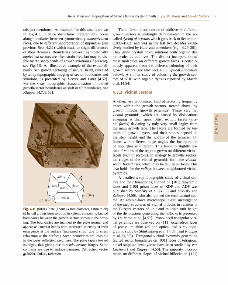
ods just mentioned. An example for this case is shownin Fig. 4.11. Lattice distortions preferentially occuralong boundaries between symmetrically nonequivalentfaces, due to different incorporation of impurities (seeprevious Sect. 4.2.1) which leads to slight differencesof their d-values. Boundaries between symmetricallyequivalent sectors are often strain-free, but may be vis-ible by the sharp bends of growth striations (if present),see Fig. 4.9. An illustrative example of the extraordi-narily rich growth sectoring of natural beryl, revealedby x-ray topographic imaging of sector boundaries andstriations, is presented by Herres and Lang [4.52].For the x-ray topographic characterisation of faultedgrowth-sector boundaries as shift or tilt boundaries, seeKlapper [4.7, 8, 53].
(0001)
(01–11)
(11–02)
(1–101)
(1–012)
(011–2)
(101–1)
g
Fig. 4.11 (0001) Plate (about 14 mm diameter, 1 mm thick)of benzil grown from solution in xylene, containing faultedboundaries between the growth sectors shown in the draw-ing. The boundaries are inclined to the plate normal andappear as contrast bands with increased intensity at theiremergence at the surface (increased strain due to stressrelaxation at the surface). Some boundaries are invisiblein the x-ray reflection used here. The plate tapers towardits edges, thus giving rise to pendelloesung fringes. Somecontrasts are due to surface damages. Diffraction vectorg(2̄020), CuKα1 radiation
The different incorporation of additives in differentgrowth sectors is strikingly demonstrated in the so-called dyeing of crystals which goes back to Sénarmont(1808–1862) and was in the last two decades exten-sively studied by Kahr and coworkers (e.g. [4.29, 30]).They grew crystals from solutions with organic dyemolecules as additives. The distinct incorporation ofthese molecules on different growth faces is conspic-uously apparent from the different colouring of theirgrowth sectors (see also Sect. 4.3.5 Optical Anomaliesbelow). A similar study of colouring the growth sec-tors of KDP with organic dyes is reported by Maedaet al. [4.54].
4.3.3 Vicinal Sectors
Another, less pronounced kind of sectoring frequentlyarises within the growth sectors, treated above, bygrowth hillocks (growth pyramids). These very flatvicinal pyramids, which are caused by dislocationsemerging at their apex, often exhibit facets (vici-nal facets) deviating by only very small angles fromthe main growth face. The facets are formed by ter-races of growth layers, and their slopes depend onthe step height and the widths of the terraces. Onfacets with different slope angles the incorporationof impurities is different. This leads to slightly dis-tinct d-values of the regions grown on different vicinalfacets (vicinal sectors). In analogy to growths sectors,the ridges of the vicinal pyramids form the vicinal-sector boundaries, which may be faulted surfaces. Thisalso holds for the valleys between neighboured vicinalpyramids.
A detailed x-ray topographic study of vicinal sec-tors and their boundaries, formed on {101} dipyramidfaces and {100} prism faces of KDP and ADP waspublished by Smolsky et al. [4.55] and Smolsky andZaitseva [4.56], who also coined the term vicinal sec-tor. An atomic-force microscope in-situ investigationof the step structures of vicinal hillocks in relation tothe Burgers vectors of unit and multiple unit heightof the dislocations generating the hillocks is presentedby De Yoreo et al. [4.57]. Pronounced triangular vici-nal pyramids are observed on {111} octahedron facesof potassium alum (cf. the optical and x-ray topo-graphic study by Shtukenberg et al. [4.58], and Klapperet al. [4.59]). Tetragonal vicinal pyramids generatingfaulted sector boundaries on {001} faces of tetragonalnickel sulphate hexahydrate have been studied by vanEnckevort and Klapper [4.60]. The impurity incorpo-ration on different slopes of vicinal hillocks on {111}
PartA
4.3
14 Part A Solid Mechanics Topics
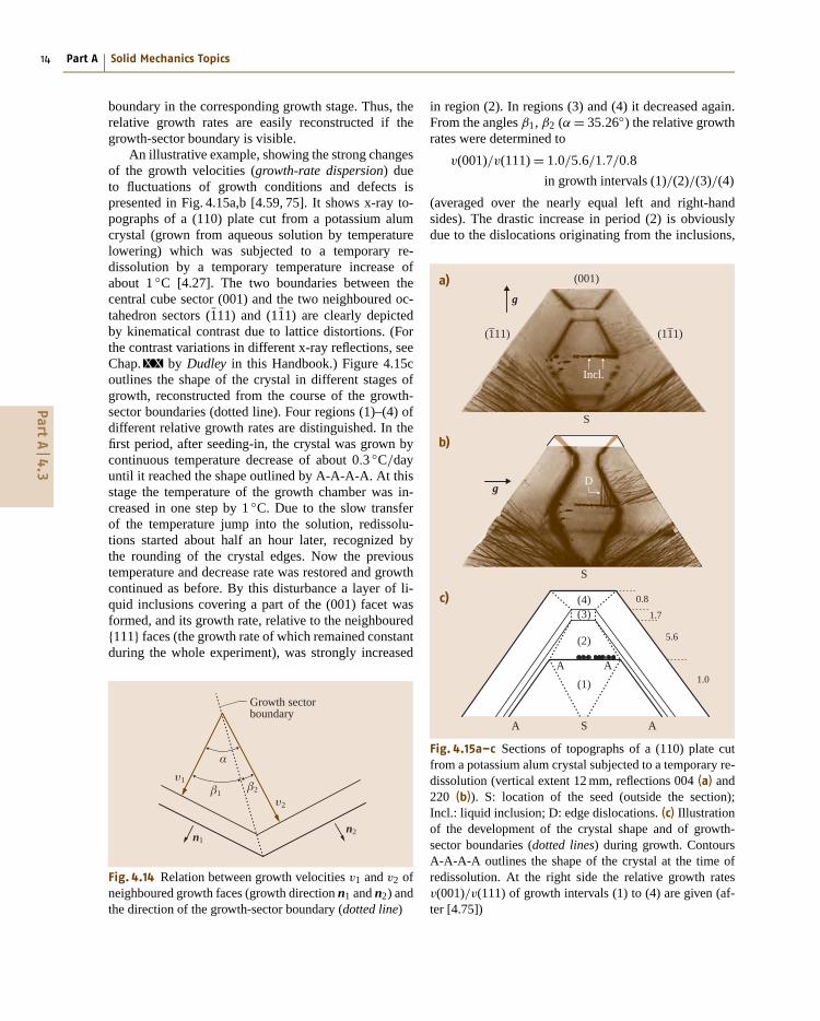
boundary in the corresponding growth stage. Thus, therelative growth rates are easily reconstructed if thegrowth-sector boundary is visible.
An illustrative example, showing the strong changesof the growth velocities (growth-rate dispersion) dueto fluctuations of growth conditions and defects ispresented in Fig. 4.15a,b [4.59, 75]. It shows x-ray to-pographs of a (110) plate cut from a potassium alumcrystal (grown from aqueous solution by temperaturelowering) which was subjected to a temporary re-dissolution by a temporary temperature increase ofabout 1 ◦C [4.27]. The two boundaries between thecentral cube sector (001) and the two neighboured oc-tahedron sectors (1̄11) and (11̄1) are clearly depictedby kinematical contrast due to lattice distortions. (Forthe contrast variations in different x-ray reflections, seeChap. XX by Dudley in this Handbook.) Figure 4.15coutlines the shape of the crystal in different stages ofgrowth, reconstructed from the course of the growth-sector boundaries (dotted line). Four regions (1)–(4) ofdifferent relative growth rates are distinguished. In thefirst period, after seeding-in, the crystal was grown bycontinuous temperature decrease of about 0.3 ◦C/dayuntil it reached the shape outlined by A-A-A-A. At thisstage the temperature of the growth chamber was in-creased in one step by 1 ◦C. Due to the slow transferof the temperature jump into the solution, redissolu-tions started about half an hour later, recognized bythe rounding of the crystal edges. Now the previoustemperature and decrease rate was restored and growthcontinued as before. By this disturbance a layer of li-quid inclusions covering a part of the (001) facet wasformed, and its growth rate, relative to the neighboured{111} faces (the growth rate of which remained constantduring the whole experiment), was strongly increased
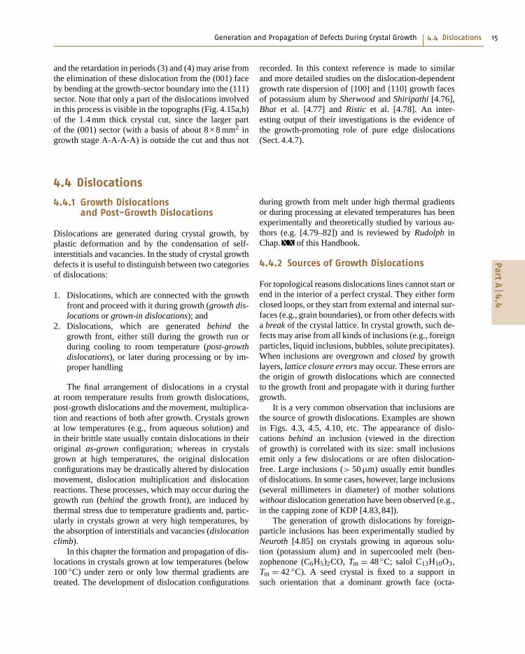
Growth sectorboundary
�2�1
υ1
υ2
α
n1n2
Fig. 4.14 Relation between growth velocities v1 and v2 ofneighboured growth faces (growth direction n1 and n2) andthe direction of the growth-sector boundary (dotted line)
in region (2). In regions (3) and (4) it decreased again.From the angles β1, β2 (α = 35.26◦) the relative growthrates were determined to
v(001)/v(111) = 1.0/5.6/1.7/0.8
in growth intervals (1)/(2)/(3)/(4)
(averaged over the nearly equal left and right-handsides). The drastic increase in period (2) is obviouslydue to the dislocations originating from the inclusions,
(11–1)
Incl.
(1–11)
S
(001)
D
S
S A
AA
A
(4)(3)
(2)
(1)
0.8
1.7
5.6
1.0
g
a)
b)
c)
g
Fig. 4.15a–c Sections of topographs of a (110) plate cutfrom a potassium alum crystal subjected to a temporary re-dissolution (vertical extent 12 mm, reflections 004 (a) and220 (b)). S: location of the seed (outside the section);Incl.: liquid inclusion; D: edge dislocations. (c) Illustrationof the development of the crystal shape and of growth-sector boundaries (dotted lines) during growth. ContoursA-A-A-A outlines the shape of the crystal at the time ofredissolution. At the right side the relative growth ratesv(001)/v(111) of growth intervals (1) to (4) are given (af-ter [4.75])
PartA
4.3
Generation and Propagation of Defects During Crystal Growth 4.4 Dislocations 15
and the retardation in periods (3) and (4) may arise fromthe elimination of these dislocation from the (001) faceby bending at the growth-sector boundary into the (111)sector. Note that only a part of the dislocations involvedin this process is visible in the topographs (Fig. 4.15a,b)of the 1.4 mm thick crystal cut, since the larger partof the (001) sector (with a basis of about 8 × 8 mm2 ingrowth stage A-A-A-A) is outside the cut and thus not
recorded. In this context reference is made to similarand more detailed studies on the dislocation-dependentgrowth rate dispersion of {100} and {110} growth facesof potassium alum by Sherwood and Shiripathi [4.76],Bhat et al. [4.77] and Ristic et al. [4.78]. An inter-esting output of their investigations is the evidence ofthe growth-promoting role of pure edge dislocations(Sect. 4.4.7).
Dislocations are generated during crystal growth, byplastic deformation and by the condensation of self-interstitials and vacancies. In the study of crystal growthdefects it is useful to distinguish between two categoriesof dislocations:
1. Dislocations, which are connected with the growthfront and proceed with it during growth (growth dis-locations or grown-in dislocations); and
2. Dislocations, which are generated behind thegrowth front, either still during the growth run orduring cooling to room temperature (post-growthdislocations), or later during processing or by im-proper handling
The final arrangement of dislocations in a crystalat room temperature results from growth dislocations,post-growth dislocations and the movement, multiplica-tion and reactions of both after growth. Crystals grownat low temperatures (e.g., from aqueous solution) andin their brittle state usually contain dislocations in theiroriginal as-grown configuration; whereas in crystalsgrown at high temperatures, the original dislocationconfigurations may be drastically altered by dislocationmovement, dislocation multiplication and dislocationreactions. These processes, which may occur during thegrowth run (behind the growth front), are induced bythermal stress due to temperature gradients and, partic-ularly in crystals grown at very high temperatures, bythe absorption of interstitials and vacancies (dislocationclimb).
In this chapter the formation and propagation of dis-locations in crystals grown at low temperatures (below100 ◦C) under zero or only low thermal gradients aretreated. The development of dislocation configurations
during growth from melt under high thermal gradientsor during processing at elevated temperatures has beenexperimentally and theoretically studied by various au-thors (e.g. [4.79–82]) and is reviewed by Rudolph inChap. XX of this Handbook.
4.4.2 Sources of Growth Dislocations
For topological reasons dislocations lines cannot start orend in the interior of a perfect crystal. They either formclosed loops, or they start from external and internal sur-faces (e.g., grain boundaries), or from other defects witha break of the crystal lattice. In crystal growth, such de-fects may arise from all kinds of inclusions (e.g., foreignparticles, liquid inclusions, bubbles, solute precipitates).When inclusions are overgrown and closed by growthlayers, lattice closure errors may occur. These errors arethe origin of growth dislocations which are connectedto the growth front and propagate with it during furthergrowth.
It is a very common observation that inclusions arethe source of growth dislocations. Examples are shownin Figs. 4.3, 4.5, 4.10, etc. The appearance of dislo-cations behind an inclusion (viewed in the directionof growth) is correlated with its size: small inclusionsemit only a few dislocations or are often dislocation-free. Large inclusions (> 50 μm) usually emit bundlesof dislocations. In some cases, however, large inclusions(several millimeters in diameter) of mother solutionswithout dislocation generation have been observed (e.g.,in the capping zone of KDP [4.83, 84]).
The generation of growth dislocations by foreign-particle inclusions has been experimentally studied byNeuroth [4.85] on crystals growing in aqueous solu-tion (potassium alum) and in supercooled melt (ben-zophenone (C6H5)2CO, Tm = 48 ◦C; salol C13H10O3,Tm = 42 ◦C). A seed crystal is fixed to a support insuch orientation that a dominant growth face (octa-
PartA
4.4
16 Part A Solid Mechanics Topics
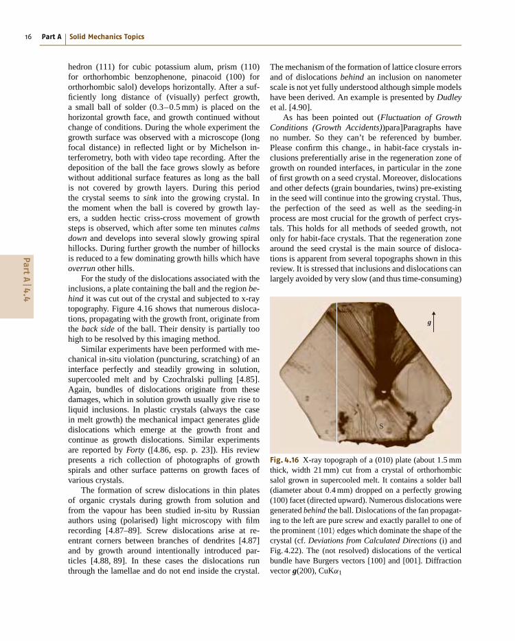
hedron (111) for cubic potassium alum, prism (110)for orthorhombic benzophenone, pinacoid (100) fororthorhombic salol) develops horizontally. After a suf-ficiently long distance of (visually) perfect growth,a small ball of solder (0.3–0.5 mm) is placed on thehorizontal growth face, and growth continued withoutchange of conditions. During the whole experiment thegrowth surface was observed with a microscope (longfocal distance) in reflected light or by Michelson in-terferometry, both with video tape recording. After thedeposition of the ball the face grows slowly as beforewithout additional surface features as long as the ballis not covered by growth layers. During this periodthe crystal seems to sink into the growing crystal. Inthe moment when the ball is covered by growth lay-ers, a sudden hectic criss-cross movement of growthsteps is observed, which after some ten minutes calmsdown and develops into several slowly growing spiralhillocks. During further growth the number of hillocksis reduced to a few dominating growth hills which haveoverrun other hills.
For the study of the dislocations associated with theinclusions, a plate containing the ball and the region be-hind it was cut out of the crystal and subjected to x-raytopography. Figure 4.16 shows that numerous disloca-tions, propagating with the growth front, originate fromthe back side of the ball. Their density is partially toohigh to be resolved by this imaging method.
Similar experiments have been performed with me-chanical in-situ violation (puncturing, scratching) of aninterface perfectly and steadily growing in solution,supercooled melt and by Czochralski pulling [4.85].Again, bundles of dislocations originate from thesedamages, which in solution growth usually give rise toliquid inclusions. In plastic crystals (always the casein melt growth) the mechanical impact generates glidedislocations which emerge at the growth front andcontinue as growth dislocations. Similar experimentsare reported by Forty ([4.86, esp. p. 23]). His reviewpresents a rich collection of photographs of growthspirals and other surface patterns on growth faces ofvarious crystals.
The formation of screw dislocations in thin platesof organic crystals during growth from solution andfrom the vapour has been studied in-situ by Russianauthors using (polarised) light microscopy with filmrecording [4.87–89]. Screw dislocations arise at re-entrant corners between branches of dendrites [4.87]and by growth around intentionally introduced par-ticles [4.88, 89]. In these cases the dislocations runthrough the lamellae and do not end inside the crystal.
The mechanism of the formation of lattice closure errorsand of dislocations behind an inclusion on nanometerscale is not yet fully understood although simple modelshave been derived. An example is presented by Dudleyet al. [4.90].
As has been pointed out (Fluctuation of GrowthConditions (Growth Accidents))para]Paragraphs haveno number. So they can’t be referenced by bumber.Please confirm this change., in habit-face crystals in-clusions preferentially arise in the regeneration zone ofgrowth on rounded interfaces, in particular in the zoneof first growth on a seed crystal. Moreover, dislocationsand other defects (grain boundaries, twins) pre-existingin the seed will continue into the growing crystal. Thus,the perfection of the seed as well as the seeding-inprocess are most crucial for the growth of perfect crys-tals. This holds for all methods of seeded growth, notonly for habit-face crystals. That the regeneration zonearound the seed crystal is the main source of disloca-tions is apparent from several topographs shown in thisreview. It is stressed that inclusions and dislocations canlargely avoided by very slow (and thus time-consuming)
g
S
Fig. 4.16 X-ray topograph of a (010) plate (about 1.5 mmthick, width 21 mm) cut from a crystal of orthorhombicsalol grown in supercooled melt. It contains a solder ball(diameter about 0.4 mm) dropped on a perfectly growing(100) facet (directed upward). Numerous dislocations weregenerated behind the ball. Dislocations of the fan propagat-ing to the left are pure screw and exactly parallel to one ofthe prominent 〈101〉 edges which dominate the shape of thecrystal (cf. Deviations from Calculated Directions (i) andFig. 4.22). The (not resolved) dislocations of the verticalbundle have Burgers vectors [100] and [001]. Diffractionvector g(200), CuKα1
PartA
4.4
Generation and Propagation of Defects During Crystal Growth 4.4 Dislocations 17
growth during the regeneration period of first growth ona perfect seed.
Finally it is emphasized that inclusions can alsoblock already existing dislocations. This has severaltimes been observed by the author and reported in theliterature. It frequently happens to dislocations in theseed crystal which are blocked by inclusions formed inthe regeneration zone (capping) of first growth and donot enter the growing crystal [4.83,84]. Thus provokinga capping zone by an intentionally introduced deviationof the seed surface from a habit face may be helpful forreducing the number of dislocations coming from theseed, but it implies also a considerable risk of generatingnew dislocations behind the inclusions. The blocking ofgrowth dislocations by closed inclusions must obey theconservation law of Burgers vectors as discussed in thefollowing Sect. 4.4.3.
4.4.3 Burgers Vectors, Dislocation Dipoles
The sum of the Burgers vectors of all dislocationsoriginating from a closed inclusion embedded in anotherwise perfect crystal is zero [4.83]. This directlyfollows from Frank’s conservation law of Burgers vec-tors (see text books on dislocations, e.g. [4.91–93])which states that the sum of Burgers vectors bi of all dis-location lines going into a dislocation node (i. e., withline direction into the node) is zero
∑bi = 0 (analo-
gous to Kirchhoff’s law of electrical currents). Anotherproof may be given via the Burgers-circuit definition ofBurgers vectors (e.g. [4.91–93]): imagine a Burgers cir-cuit parallel the growth face in the perfect crystal regiongrown before the inclusion was formed. Now shift thecircuit stepwise in growth direction over the inclusionand the dislocation bundle behind it. No closure errorof the circuit, which now encircles all dislocations, willarise during this (virtual) procedure:
∑bi = 0.
From this it immediately follows that a singledislocation cannot originate from an inclusion. If dislo-cations are formed, there must be at least two of them,with opposite Burgers vectors. This is often observedwhen the inclusions are very small. Two slightly di-verging dislocation lines emanating from small, x-raytopographically invisible or nearly invisible inclusionswere observed in KDP by Fishman [4.83]. Examplesare presented in Fig. 4.19 (label A) for salol grown fromsupercooled melt. A few pairs of slightly diverging dis-locations, starting from a point, can also be recognizedin Fig. 4.10 of a Czochralski salol specimen. There are,however, many x-ray topographic observations of onlyone dislocation line arising from an inclusion (e.g., in
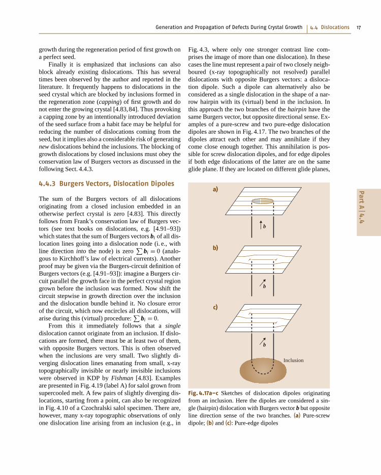
Fig. 4.3, where only one stronger contrast line com-prises the image of more than one dislocation). In thesecases the line must represent a pair of two closely neigh-boured (x-ray topographically not resolved) paralleldislocations with opposite Burgers vectors: a disloca-tion dipole. Such a dipole can alternatively also beconsidered as a single dislocation in the shape of a nar-row hairpin with its (virtual) bend in the inclusion. Inthis approach the two branches of the hairpin have thesame Burgers vector, but opposite directional sense. Ex-amples of a pure-screw and two pure-edge dislocationdipoles are shown in Fig. 4.17. The two branches of thedipoles attract each other and may annihilate if theycome close enough together. This annihilation is pos-sible for screw dislocation dipoles, and for edge dipolesif both edge dislocations of the latter are on the sameglide plane. If they are located on different glide planes,
a)
b)
c)
Inclusion
b
b
b
Fig. 4.17a–c Sketches of dislocation dipoles originatingfrom an inclusion. Here the dipoles are considered a sin-gle (hairpin) dislocation with Burgers vector b but oppositeline direction sense of the two branches. (a) Pure-screwdipole; (b) and (c): Pure-edge dipoles
PartA
4.4
18 Part A Solid Mechanics Topics
i
i
Seedcrystal
n
n
n
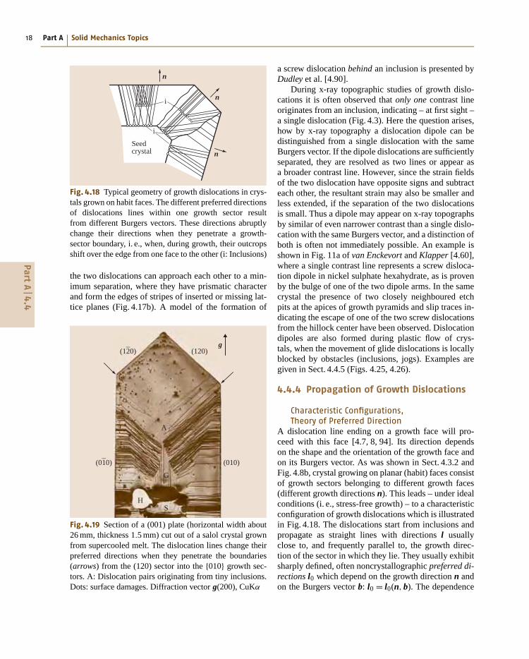
Fig. 4.18 Typical geometry of growth dislocations in crys-tals grown on habit faces. The different preferred directionsof dislocations lines within one growth sector resultfrom different Burgers vectors. These directions abruptlychange their directions when they penetrate a growth-sector boundary, i. e., when, during growth, their outcropsshift over the edge from one face to the other (i: Inclusions)
the two dislocations can approach each other to a min-imum separation, where they have prismatic characterand form the edges of stripes of inserted or missing lat-tice planes (Fig. 4.17b). A model of the formation of
(120)
(010)
HS
G
A
(12–0)
(01–
0)
g
Fig. 4.19 Section of a (001) plate (horizontal width about26 mm, thickness 1.5 mm) cut out of a salol crystal grownfrom supercooled melt. The dislocation lines change theirpreferred directions when they penetrate the boundaries(arrows) from the (120) sector into the {010} growth sec-tors. A: Dislocation pairs originating from tiny inclusions.Dots: surface damages. Diffraction vector g(200), CuKα
a screw dislocation behind an inclusion is presented byDudley et al. [4.90].
During x-ray topographic studies of growth dislo-cations it is often observed that only one contrast lineoriginates from an inclusion, indicating – at first sight –a single dislocation (Fig. 4.3). Here the question arises,how by x-ray topography a dislocation dipole can bedistinguished from a single dislocation with the sameBurgers vector. If the dipole dislocations are sufficientlyseparated, they are resolved as two lines or appear asa broader contrast line. However, since the strain fieldsof the two dislocation have opposite signs and subtracteach other, the resultant strain may also be smaller andless extended, if the separation of the two dislocationsis small. Thus a dipole may appear on x-ray topographsby similar of even narrower contrast than a single dislo-cation with the same Burgers vector, and a distinction ofboth is often not immediately possible. An example isshown in Fig. 11a of van Enckevort and Klapper [4.60],where a single contrast line represents a screw disloca-tion dipole in nickel sulphate hexahydrate, as is provenby the bulge of one of the two dipole arms. In the samecrystal the presence of two closely neighboured etchpits at the apices of growth pyramids and slip traces in-dicating the escape of one of the two screw dislocationsfrom the hillock center have been observed. Dislocationdipoles are also formed during plastic flow of crys-tals, when the movement of glide dislocations is locallyblocked by obstacles (inclusions, jogs). Examples aregiven in Sect. 4.4.5 (Figs. 4.25, 4.26).
4.4.4 Propagation of Growth Dislocations
Characteristic Configurations,Theory of Preferred Direction
A dislocation line ending on a growth face will pro-ceed with this face [4.7, 8, 94]. Its direction dependson the shape and the orientation of the growth face andon its Burgers vector. As was shown in Sect. 4.3.2 andFig. 4.8b, crystal growing on planar (habit) faces consistof growth sectors belonging to different growth faces(different growth directions n). This leads – under idealconditions (i. e., stress-free growth) – to a characteristicconfiguration of growth dislocations which is illustratedin Fig. 4.18. The dislocations start from inclusions andpropagate as straight lines with directions l usuallyclose to, and frequently parallel to, the growth direc-tion of the sector in which they lie. They usually exhibitsharply defined, often noncrystallographic preferred di-rections l0 which depend on the growth direction n andon the Burgers vector b: l0 = l0(n, b). The dependence
PartA
4.4
Generation and Propagation of Defects During Crystal Growth 4.4 Dislocations 19
of the preferred direction l0 on the growth direction nbecomes strikingly apparent when the dislocations pen-etrate growth-sector boundaries. This implies an abruptchange of the growth direction: the dislocation lines un-dergo an abrupt change of their preferred direction l0.An example is shown in Fig. 4.19.
These preferred direction of growth dislocations areexplained by two approaches [4.7, 8, 94]:
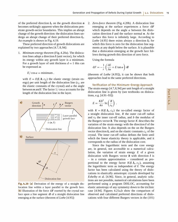
1. Minimum-energy theorem (Fig. 4.20a). The disloca-tion lines adopt a direction l (unit vector), for whichits energy within any growth layer is a minimum.For a growth layer of unit thickness d = 1 this canbe expressed as
E/ cos α = minimum ,
with E = E(l, b, cij ) the elastic energy (strain en-ergy) per unit length of the dislocation line (cij arethe elastic constants of the crystal) and α the anglebetween n and l. The factor 1/ cos α accounts for thelength of the dislocation line in the layer.
a)
b)
Burgersvector
Growthdirection
Dislocation line
Dislocation line
dl
rdF
Surface
Layer parallelgrowth face
α (n, l )
α
bl
d
n
Fig. 4.20 (a) Derivation of the energy of a straight dis-location line within a layer parallel to the growth face.(b) Illustration of the force dF exerted by the crystal sur-face upon a line segment dl of a straight dislocation lineemerging at the surface (theorem of Lothe [4.95])
2. Zero-force theorem (Fig. 4.20b). A dislocation lineemerging at the surface experiences a force dFwhich depends on the angle α between the dislo-cation direction l and the surface normal n. At thesurface this force is infinitely large. According toLothe [4.95] there exists always a direction l0 forwhich this force is zero for the dislocation line seg-ments at any depth below the surface. It is plausiblethat a dislocation emerging at the growth face fol-lows during growth this direction of zero force.
Using the formula
dF = −1
r
(∂E
∂α+ E tan α
)dl
(theorem of Lothe [4.95]), it can be shown that bothapproaches lead to the same preferred directions.
Verification of the Minimum-Energy ApproachThe strain energy [4.7,8,94] per unit length of a straightdislocation line is given by (see textbooks on disloca-tions, e.g. [4.91–93])
E = Kb2
4πln
(R
r0
),
with K = K (l, lb, cij ) the so-called energy factor ofa straight dislocation line, R the outer cut-off radiusand r0 the inner cut-off radius, and b the modulus ofthe Burgers vector b. The energy factor K describes thevariation of the strain energy with the direction l of thedislocation line. It also depends on the on the Burgersvector direction lb and on the elastic constants cij of thecrystal. The inner cut-off radius defines the limit untilwhich the linear elasticity theory is applicable, and itcorresponds to the radius of the dislocation core.
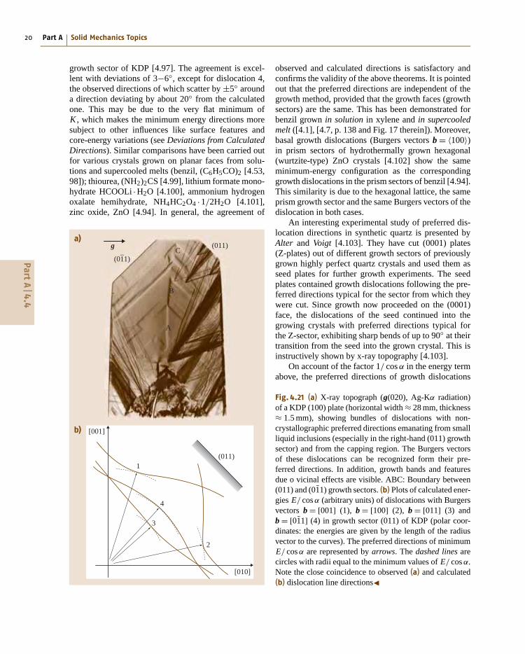
Since the logarithmic term and the core energyare, in general, not accessible to a numerical calcu-lation, the variation of strain energy E of a givendislocation with Burgers vector b with direction l is– in a certain approximation – considered as pro-portional to the energy factor K (l, lb, cij ), assumingthe logarithmic term as independent of l. The energyfactor has been calculated using the theory of dislo-cations in elastically anisotropic crystals developed byEshelby et al. [4.96]. Since, in general, analytic solu-tions are not possible, numerical calculations have beenperformed using a program DISLOC, accounting forelastic anisotropy of any symmetry down to the tricliniccase [4.94]. Figures 4.21a,b show the comparison ofobserved and calculated preferred directions of dislo-cations with four different Burgers vectors in the (101)
PartA
4.4
20 Part A Solid Mechanics Topics
growth sector of KDP [4.97]. The agreement is excel-lent with deviations of 3−6◦, except for dislocation 4,the observed directions of which scatter by ±5◦ arounda direction deviating by about 20◦ from the calculatedone. This may be due to the very flat minimum ofK , which makes the minimum energy directions moresubject to other influences like surface features andcore-energy variations (see Deviations from CalculatedDirections). Similar comparisons have been carried outfor various crystals grown on planar faces from solu-tions and supercooled melts (benzil, (C6H5CO)2 [4.53,98]); thiourea, (NH2)2CS [4.99], lithium formate mono-hydrate HCOOLi ·H2O [4.100], ammonium hydrogenoxalate hemihydrate, NH4HC2O4 ·1/2H2O [4.101],zinc oxide, ZnO [4.94]. In general, the agreement of
[010]
[001]
a)
b)
(011)
(011)
1
4
3
2
A
B
C(01
–1)
g
observed and calculated directions is satisfactory andconfirms the validity of the above theorems. It is pointedout that the preferred directions are independent of thegrowth method, provided that the growth faces (growthsectors) are the same. This has been demonstrated forbenzil grown in solution in xylene and in supercooledmelt ([4.1], [4.7, p. 138 and Fig. 17 therein]). Moreover,basal growth dislocations (Burgers vectors b = 〈100〉)in prism sectors of hydrothermally grown hexagonal(wurtzite-type) ZnO crystals [4.102] show the sameminimum-energy configuration as the correspondinggrowth dislocations in the prism sectors of benzil [4.94].This similarity is due to the hexagonal lattice, the sameprism growth sector and the same Burgers vectors of thedislocation in both cases.
An interesting experimental study of preferred dis-location directions in synthetic quartz is presented byAlter and Voigt [4.103]. They have cut (0001) plates(Z-plates) out of different growth sectors of previouslygrown highly perfect quartz crystals and used them asseed plates for further growth experiments. The seedplates contained growth dislocations following the pre-ferred directions typical for the sector from which theywere cut. Since growth now proceeded on the (0001)face, the dislocations of the seed continued into thegrowing crystals with preferred directions typical forthe Z-sector, exhibiting sharp bends of up to 90◦ at theirtransition from the seed into the grown crystal. This isinstructively shown by x-ray topography [4.103].
On account of the factor 1/ cos α in the energy termabove, the preferred directions of growth dislocations
Fig. 4.21 (a) X-ray topograph (g(020), Ag-Kα radiation)of a KDP (100) plate (horizontal width ≈ 28 mm, thickness≈ 1.5 mm), showing bundles of dislocations with non-crystallographic preferred directions emanating from smallliquid inclusions (especially in the right-hand (011) growthsector) and from the capping region. The Burgers vectorsof these dislocations can be recognized form their pre-ferred directions. In addition, growth bands and featuresdue o vicinal effects are visible. ABC: Boundary between(011) and (01̄1) growth sectors. (b) Plots of calculated ener-gies E/ cos α (arbitrary units) of dislocations with Burgersvectors b = [001] (1), b = [100] (2), b = [011] (3) andb = [01̄1] (4) in growth sector (011) of KDP (polar coor-dinates: the energies are given by the length of the radiusvector to the curves). The preferred directions of minimumE/ cos α are represented by arrows. The dashed lines arecircles with radii equal to the minimum values of E/ cos α.Note the close coincidence to observed (a) and calculated(b) dislocation line directions�
PartA
4.4
Generation and Propagation of Defects During Crystal Growth 4.4 Dislocations 21
are mostly normal or nearly normal to the (local) growthface. In some cases of planar interfaces, however, devia-tions from the growth normal of up to 30◦ have been ob-served in agreement with the calculations. For interfaceswith convex curvature (e.g., in Czochralski growth) thedislocation lines diverge and grow out of the crystalboule through its side faces, whereas for concave inter-faces the dislocation lines are focussed into the centerof the crystal boule (Fig. 4.10). Trajectories of growthdislocations in Czochralski gadolinium gallium garnet(GGG) have been calculated and compared with ob-served ones by Schmidt and Weiss [4.68]. The curvatureof the interface has been taken into account by per-forming the calculations stepwise in small increments,leading to curved dislocation trajectories. Again theagreement is satisfactory. Moreover, it allowed assign-ing Burgers vectors to the different dislocation trajecto-ries which were observed optically in polarised light.
In 1997 and following years, preferred dislocationsdirections and their bending when penetrating a growth
g
S
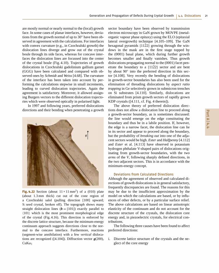
Fig. 4.22 Section (about 11 × 11 mm2) of a (010) plate(about 1.3 mm thick) cut out of the cone region ofa Czochralski salol (pulling direction [100] upward;S: seed crystal, broken off). The topograph shows manystraight dislocation lines (b = [101]) exactly parallel to〈101〉 which is the most prominent morphological edgeof the crystal (Fig. 4.16). This direction is enforced bythe discrete lattice structure, because the minimum-energycontinuum approach suggests directions close to the nor-mal to the concave interface. Furthermore, reactions(segment-wise annihilation) with a few vertical disloca-tions are recognized ([4.104]). Diffraction vector g(200),CuKα1
sector boundary have been observed by transmissionelectron microscopy in GaN grown by MOVPE (metal-organic vapour phase epitaxy) using the ELO (epitaxiallateral overgrowth) technique [4.105–109]. The GaNhexagonal pyramids {112̄2} growing through the win-dows in the mask are in the first stage topped bythe (0001) basal plane, which during further growthbecomes smaller and finally vanishes. Thus growthdislocations propagating normal to the (0001) facet pen-etrate the boundary to a {112̄2} sector and are bentby about 90◦ into the preferred direction in this sec-tor [4.108]. Very recently the bending of dislocationsin growth-sector boundaries has also been used for theelimination of threading dislocations by aspect ratiotrapping in Ge selectively grown in submicron trencheson Si substrates [4.110]. Similarly, dislocations areeliminated from prism growth sectors of rapidly grownKDP crystals ([4.111, cf. Fig. 4 therein]).
The above theory of preferred dislocation direc-tions does not allow a dislocation line to proceed alonga growth-sector boundary, as is sometimes discussed:the line would emerge on the edge constituting theboundary and thus be in a labile position. If, however,the edge is a narrow facet, the dislocation line can liein its sector and appear to proceed along the boundary,but the probability of breaking out into one of the adja-cent sectors would be high. Ester and Halfpenny [4.112]and Ester et al. [4.113] have observed in potassiumhydrogen phthalate V-shaped pairs of dislocations orig-inating from growth-sector boundaries, with the twoarms of the V, following sharply defined directions, inthe two adjacent sectors. This is in accordance with theminimum-energy concept.
Deviations from Calculated DirectionsAlthough the agreement of observed and calculated di-rections of growth dislocations is in general satisfactory,frequently discrepancies are found. The reasons for thismay be due to the insufficient approximation by themodel on which the calculations are based, or by influ-ences of other defects, or by a particular surface relief.The above calculations are based on linear anisotropicelasticity of the continuum and do not account for thediscrete structure of the crystals, the dislocation coreenergy and, in piezoelectric crystals, for electrical con-tributions.
The following three causes have been found to affectpreferred directions:
i. Discrete lattice structure of the crystals and the ne-glect of the core energy
PartA
4.4
Generation and Propagation of Defects During Crystal Growth 4.4 Dislocations 25
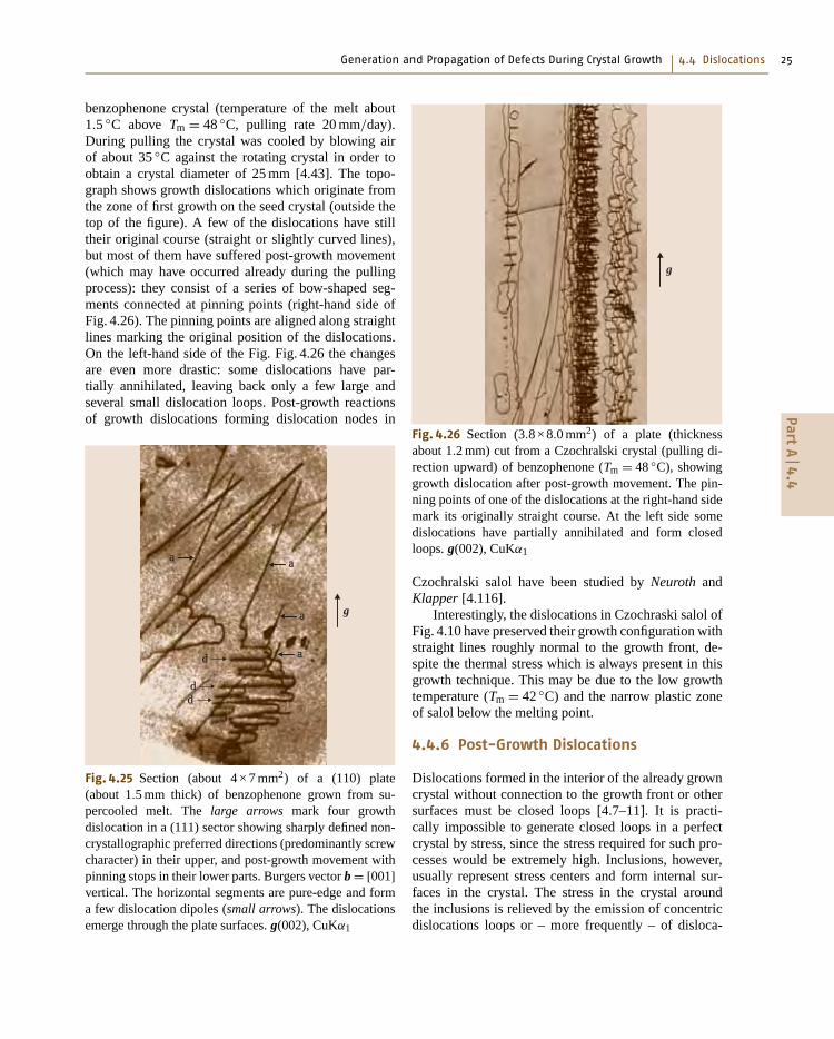
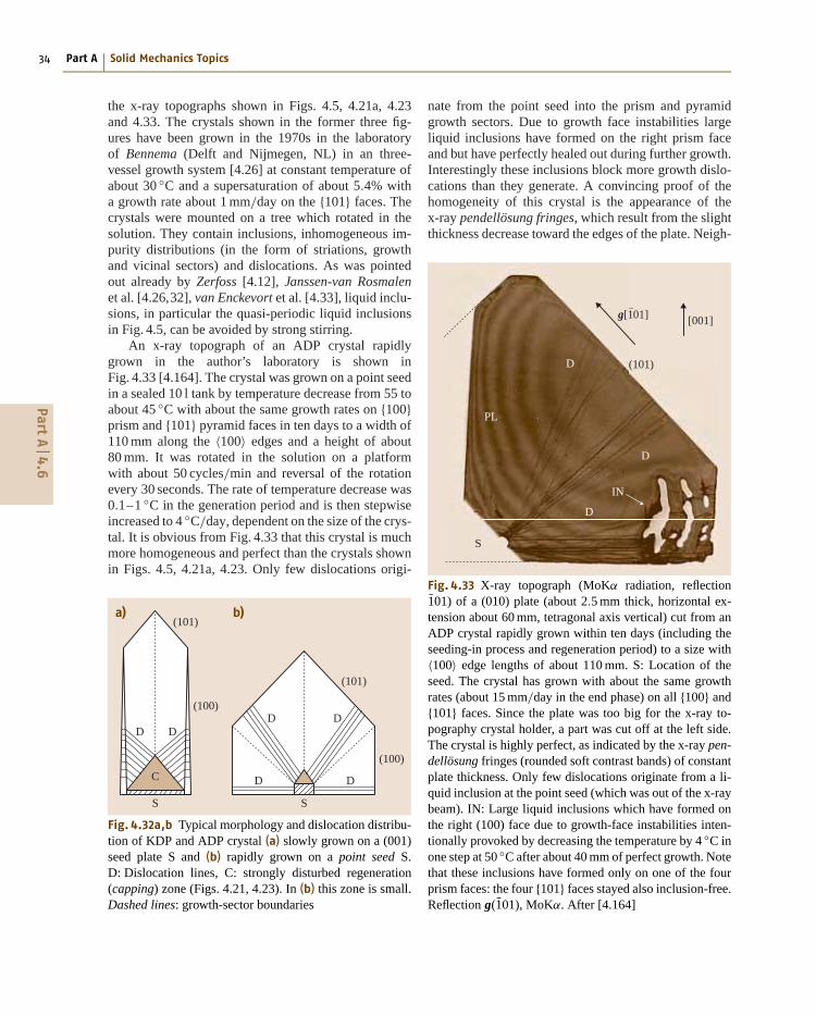
benzophenone crystal (temperature of the melt about1.5 ◦C above Tm = 48 ◦C, pulling rate 20 mm/day).During pulling the crystal was cooled by blowing airof about 35 ◦C against the rotating crystal in order toobtain a crystal diameter of 25 mm [4.43]. The topo-graph shows growth dislocations which originate fromthe zone of first growth on the seed crystal (outside thetop of the figure). A few of the dislocations have stilltheir original course (straight or slightly curved lines),but most of them have suffered post-growth movement(which may have occurred already during the pullingprocess): they consist of a series of bow-shaped seg-ments connected at pinning points (right-hand side ofFig. 4.26). The pinning points are aligned along straightlines marking the original position of the dislocations.On the left-hand side of the Fig. Fig. 4.26 the changesare even more drastic: some dislocations have par-tially annihilated, leaving back only a few large andseveral small dislocation loops. Post-growth reactionsof growth dislocations forming dislocation nodes in
d a
g
a
dd
a
a
Fig. 4.25 Section (about 4 × 7 mm2) of a (110) plate(about 1.5 mm thick) of benzophenone grown from su-percooled melt. The large arrows mark four growthdislocation in a (111) sector showing sharply defined non-crystallographic preferred directions (predominantly screwcharacter) in their upper, and post-growth movement withpinning stops in their lower parts. Burgers vector b = [001]vertical. The horizontal segments are pure-edge and forma few dislocation dipoles (small arrows). The dislocationsemerge through the plate surfaces. g(002), CuKα1
g
Fig. 4.26 Section (3.8 × 8.0 mm2) of a plate (thicknessabout 1.2 mm) cut from a Czochralski crystal (pulling di-rection upward) of benzophenone (Tm = 48 ◦C), showinggrowth dislocation after post-growth movement. The pin-ning points of one of the dislocations at the right-hand sidemark its originally straight course. At the left side somedislocations have partially annihilated and form closedloops. g(002), CuKα1
Czochralski salol have been studied by Neuroth andKlapper [4.116].
Interestingly, the dislocations in Czochraski salol ofFig. 4.10 have preserved their growth configuration withstraight lines roughly normal to the growth front, de-spite the thermal stress which is always present in thisgrowth technique. This may be due to the low growthtemperature (Tm = 42 ◦C) and the narrow plastic zoneof salol below the melting point.
4.4.6 Post-Growth Dislocations
Dislocations formed in the interior of the already growncrystal without connection to the growth front or othersurfaces must be closed loops [4.7–11]. It is practi-cally impossible to generate closed loops in a perfectcrystal by stress, since the stress required for such pro-cesses would be extremely high. Inclusions, however,usually represent stress centers and form internal sur-faces in the crystal. The stress in the crystal aroundthe inclusions is relieved by the emission of concentricdislocations loops or – more frequently – of disloca-
PartA
4.4
34 Part A Solid Mechanics Topics
the x-ray topographs shown in Figs. 4.5, 4.21a, 4.23and 4.33. The crystals shown in the former three fig-ures have been grown in the 1970s in the laboratoryof Bennema (Delft and Nijmegen, NL) in an three-vessel growth system [4.26] at constant temperature ofabout 30 ◦C and a supersaturation of about 5.4% witha growth rate about 1 mm/day on the {101} faces. Thecrystals were mounted on a tree which rotated in thesolution. They contain inclusions, inhomogeneous im-purity distributions (in the form of striations, growthand vicinal sectors) and dislocations. As was pointedout already by Zerfoss [4.12], Janssen-van Rosmalenet al. [4.26,32], van Enckevort et al. [4.33], liquid inclu-sions, in particular the quasi-periodic liquid inclusionsin Fig. 4.5, can be avoided by strong stirring.
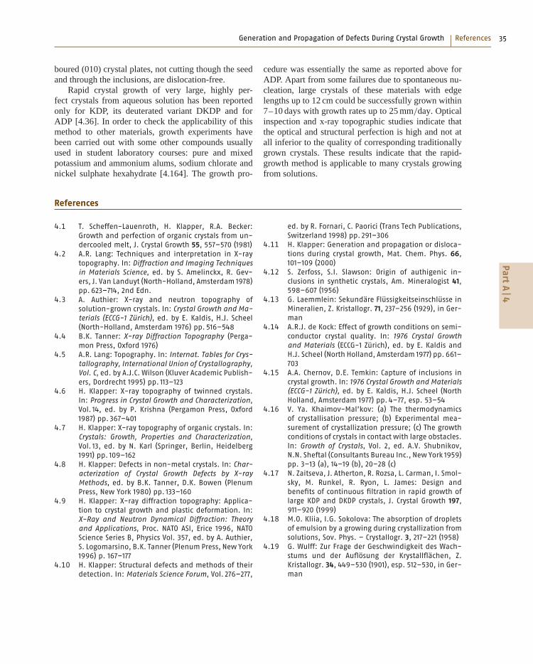
An x-ray topograph of an ADP crystal rapidlygrown in the author’s laboratory is shown inFig. 4.33 [4.164]. The crystal was grown on a point seedin a sealed 10 l tank by temperature decrease from 55 toabout 45 ◦C with about the same growth rates on {100}prism and {101} pyramid faces in ten days to a width of110 mm along the 〈100〉 edges and a height of about80 mm. It was rotated in the solution on a platformwith about 50 cycles/min and reversal of the rotationevery 30 seconds. The rate of temperature decrease was0.1–1 ◦C in the generation period and is then stepwiseincreased to 4 ◦C/day, dependent on the size of the crys-tal. It is obvious from Fig. 4.33 that this crystal is muchmore homogeneous and perfect than the crystals shownin Figs. 4.5, 4.21a, 4.23. Only few dislocations origi-
a) b)(101)
(101)
(100)
(100)
DDDD
DDC
S S
Fig. 4.32a,b Typical morphology and dislocation distribu-tion of KDP and ADP crystal (a) slowly grown on a (001)seed plate S and (b) rapidly grown on a point seed S.D: Dislocation lines, C: strongly disturbed regeneration(capping) zone (Figs. 4.21, 4.23). In (b) this zone is small.Dashed lines: growth-sector boundaries
nate from the point seed into the prism and pyramidgrowth sectors. Due to growth face instabilities largeliquid inclusions have formed on the right prism faceand but have perfectly healed out during further growth.Interestingly these inclusions block more growth dislo-cations than they generate. A convincing proof of thehomogeneity of this crystal is the appearance of thex-ray pendellösung fringes, which result from the slightthickness decrease toward the edges of the plate. Neigh-
(101)
[001]
D
D
D
PL
IN
S
g[1–01]
Fig. 4.33 X-ray topograph (MoKα radiation, reflection1̄01) of a (010) plate (about 2.5 mm thick, horizontal ex-tension about 60 mm, tetragonal axis vertical) cut from anADP crystal rapidly grown within ten days (including theseeding-in process and regeneration period) to a size with〈100〉 edge lengths of about 110 mm. S: Location of theseed. The crystal has grown with about the same growthrates (about 15 mm/day in the end phase) on all {100} and{101} faces. Since the plate was too big for the x-ray to-pography crystal holder, a part was cut off at the left side.The crystal is highly perfect, as indicated by the x-ray pen-dellösung fringes (rounded soft contrast bands) of constantplate thickness. Only few dislocations originate from a li-quid inclusion at the point seed (which was out of the x-raybeam). IN: Large liquid inclusions which have formed onthe right (100) face due to growth-face instabilities inten-tionally provoked by decreasing the temperature by 4 ◦C inone step at 50 ◦C after about 40 mm of perfect growth. Notethat these inclusions have formed only on one of the fourprism faces: the four {101} faces stayed also inclusion-free.Reflection g(1̄01), MoKα. After [4.164]
PartA
4.6
Generation and Propagation of Defects During Crystal Growth References 35
boured (010) crystal plates, not cutting though the seedand through the inclusions, are dislocation-free.
Rapid crystal growth of very large, highly per-fect crystals from aqueous solution has been reportedonly for KDP, its deuterated variant DKDP and forADP [4.36]. In order to check the applicability of thismethod to other materials, growth experiments havebeen carried out with some other compounds usuallyused in student laboratory courses: pure and mixedpotassium and ammonium alums, sodium chlorate andnickel sulphate hexahydrate [4.164]. The growth pro-
cedure was essentially the same as reported above forADP. Apart from some failures due to spontaneous nu-cleation, large crystals of these materials with edgelengths up to 12 cm could be successfully grown within7–10 days with growth rates up to 25 mm/day. Opticalinspection and x-ray topographic studies indicate thatthe optical and structural perfection is high and not atall inferior to the quality of corresponding traditionallygrown crystals. These results indicate that the rapid-growth method is applicable to many crystals growingfrom solutions.
References
4.1 T. Scheffen-Lauenroth, H. Klapper, R.A. Becker:Growth and perfection of organic crystals from un-dercooled melt, J. Crystal Growth 55, 557–570 (1981)
4.2 A.R. Lang: Techniques and interpretation in X-raytopography. In: Diffraction and Imaging Techniquesin Materials Science, ed. by S. Amelinckx, R. Gev-ers, J. Van Landuyt (North-Holland, Amsterdam 1978)pp. 623–714, 2nd Edn.
4.3 A. Authier: X-ray and neutron topography ofsolution-grown crystals. In: Crystal Growth and Ma-terials (ECCG-1 Zürich), ed. by E. Kaldis, H.J. Scheel(North-Holland, Amsterdam 1976) pp. 516–548
4.5 A.R. Lang: Topography. In: Internat. Tables for Crys-tallography, International Union of Crystallography,Vol. C, ed. by A.J.C. Wilson (Kluver Academic Publish-ers, Dordrecht 1995) pp. 113–123
4.6 H. Klapper: X-ray topography of twinned crystals.In: Progress in Crystal Growth and Characterization,Vol. 14, ed. by P. Krishna (Pergamon Press, Oxford1987) pp. 367–401
4.7 H. Klapper: X-ray topography of organic crystals. In:Crystals: Growth, Properties and Characterization,Vol. 13, ed. by N. Karl (Springer, Berlin, Heidelberg1991) pp. 109–162
4.8 H. Klapper: Defects in non-metal crystals. In: Char-acterization of Crystal Growth Defects by X-rayMethods, ed. by B.K. Tanner, D.K. Bowen (PlenumPress, New York 1980) pp. 133–160
4.9 H. Klapper: X-ray diffraction topography: Applica-tion to crystal growth and plastic deformation. In:X-Ray and Neutron Dynamical Diffraction: Theoryand Applications, Proc. NATO ASI, Erice 1996, NATOScience Series B, Physics Vol. 357, ed. by A. Authier,S. Logomarsino, B.K. Tanner (Plenum Press, New York1996) p. 167–177
4.10 H. Klapper: Structural defects and methods of theirdetection. In: Materials Science Forum, Vol. 276–277,
ed. by R. Fornari, C. Paorici (Trans Tech Publications,Switzerland 1998) pp. 291–306
4.11 H. Klapper: Generation and propagation or disloca-tions during crystal growth, Mat. Chem. Phys. 66,101–109 (2000)
4.12 S. Zerfoss, S.I. Slawson: Origin of authigenic in-clusions in synthetic crystals, Am. Mineralogist 41,598–607 (1956)
4.13 G. Laemmlein: Sekundäre Flüssigkeitseinschlüsse inMineralien, Z. Kristallogr. 71, 237–256 (1929), in Ger-man
4.14 A.R.J. de Kock: Effect of growth conditions on semi-conductor crystal quality. In: 1976 Crystal Growthand Materials (ECCG-1 Zürich), ed. by E. Kaldis andH.J. Scheel (North Holland, Amsterdam 1977) pp. 661–703
4.15 A.A. Chernov, D.E. Temkin: Capture of inclusions incrystal growth. In: 1976 Crystal Growth and Materials(ECCG-1 Zürich), ed. by E. Kaldis, H.J. Scheel (NorthHolland, Amsterdam 1977) pp. 4–77, esp. 53–54
4.16 V. Ya. Khaimov-Mal’kov: (a) The thermodynamicsof crystallisation pressure; (b) Experimental mea-surement of crystallization pressure; (c) The growthconditions of crystals in contact with large obstacles.In: Growth of Crystals, Vol. 2, ed. A.V. Shubnikov,N.N. Sheftal (Consultants Bureau Inc., New York 1959)pp. 3–13 (a), 14–19 (b), 20–28 (c)
4.17 N. Zaitseva, J. Atherton, R. Rozsa, L. Carman, I. Smol-sky, M. Runkel, R. Ryon, L. James: Design andbenefits of continuous filtration in rapid growth oflarge KDP and DKDP crystals, J. Crystal Growth 197,911–920 (1999)
4.18 M.O. Kliia, I.G. Sokolova: The absorption of dropletsof emulsion by a growing during crystallization fromsolutions, Sov. Phys. – Crystallogr. 3, 217–221 (1958)
4.19 G. Wulff: Zur Frage der Geschwindigkeit des Wach-stums und der Auflösung der Krystallflächen, Z.Kristallogr. 34, 449–530 (1901), esp. 512–530, in Ger-man
PartA
4
36 Part A Solid Mechanics Topics
4.20 R.F. Strickland-Constable: Kinetics and Mechanismsof Crystallisation (Academic Press, London, New York1968) pp. 76–84
4.21 P. Bennema: Generalized Herring treatment of theequilibrium form. In: Crystal growth: An introduc-tion, North-Holland Series in Crystal Growth I, ed. byP. Hartman (North-Holland, Amsterdam 1973), pp.342–357
4.22 C. Herring: Some theorems on the free energies ofcrystal surfaces, Phys. Rev. 82, 87–93 (1951)
4.23 C. Herring: The use of classical macroscopic con-cepts in surface energy problems. In: Structure andProperties of Solid Surfaces, ed. by R.G. Gromer,C.S. Smith (University of Chicago Press, Chicago 1953)pp. 5–72
4.24 W. Schnoor: Über das Wachstum von Auflösungskör-pern und Kugeln aus Steinsalz, Z. Kristallogr. 68,1–14 (1928), in German
4.26 R. Janssen-Van Rosmalen, W.H. van der Linden,E. Dobinga, D. Visser: The influence of the hy-drodynamic environment on the growth and theformation of liquid inclusions in large potassiumhydrogen phosphate crystals, Kristall und Technik13, 17–28 (1978)
4.27 A. Faber: Röntgentopographische Untersuchungenvon Wachstumsstörungen durch alternierende Tem-peraturgradienten im Kali-Alaun. Studienarbeit(Inst. f. Kristallographie, RWTH Aachen 1980), in Ger-man
4.28 W.M. Vetter, H. Totsuka, M. Dudley, B. Kahr: Theperfection and defect structures of organic hour-glass inclusion K2SO4 crystals, J. Crystal Growth 241,498–506 (2002)
4.30 B. Kahr, L. Vasquez: Painting crystals, Cryst. Eng.Comm. 4, 514–516 (2002)
4.31 A.A. Chernov, G. Yu. Kuznetsov, I.L. Smol’skii,V.N. Rozhanski: Hydrodynamic effects during ADPgrowth from aqueous solutions in the kineticregime, Sov. Phys. -Crystallogr. 31, 705–709 (1986)
4.32 R. Janssen-Van Rosmalen, P. Bennema: The role ofhydrodynamics and supersaturation in the forma-tion of fluid inclusions in KDP, J. Crystal Growth 42,224–227 (1977)
4.33 W.J.P. van Enckevort, R. Janssen-van Rosmalen,H. Klapper, W.H. van der Linden: Growth phe-nomena of KDP crystals in relation to the internalstructure, J. Crystal Growth 60, 67–78 (1982)
4.34 N.P. Zaitseva, I.L. Smolsky, L.N. Rashkovich: Study ofrapid growth of KDP crystals by temperature lower-ing, Sov. Phys. - Crystallogr. 36, 113–115 (1991)
4.35 N.P. Zaitseva, J.J. De Yoreo, M.R. Dehaven, R.L. Vi-tal, K.E. Montgomery, M. Richardson, L.J. Atherton:Rapid growth of large-scale (40–55 cm) KH2PO4
crystals, J. Crystal Growth 180, 255–262 (1997)
4.36 N. Zaitseva, L. Carman: Rapid Growth of KDP-typeCrystals, Progr. Crystal Growth Characteriz. Mater. 43,1–118 (2001)
4.37 I. Smolsky, J.J. de Yoreo, N.P. Zaitseva, J.D. Lee,T.A. Land, E.B. Rudneva: Oriented liquid inclusionsin KDP crystals, J. Crystal Growth 169, 741–745 (1996)
4.38 E. Scandale, A. Zarka: Sur l’origine des canaux dansles cristaux, J. Appl. Cryst. 15, 417–422 (1982)
4.39 X.R. Huang, M. Dudley, W.M. Vetter, W. Huang,S. Wang, C.H. Carter Jr.: Direct evidence ofmicropipe-related pure superscrew dislocations inSiC, Appl. Phys. Lett. 74, 353–355 (1999)
4.40 J. Heindl, H.P. Strunk, V.D. Heydemann, G. Pensl:Micropipes: Hollow tubes in silicon carbide, Phys.Stat. Sol. 162, 251–262 (1997)
4.41 H.P. Strunk, W. Dorsch, J. Heindl: The nature ofmicropipes in 6H-SiC single crystals, Advan. Eng.Materials 2, 386–389 (2000)
4.42 E. Roedder: Fluid inclusions. In: Reviews in Mineral-ogy, Vol. 12, ed. by P.H. Ribbe (Mineralogical Societyof America, BookCrafters, Inc., Chelsea 1984)
4.43 Th. Scheffen-Lauenroth: Czochralski-Züchtung undPerfektion organischer Kristalle. Diplomarbeit (Inst.f. Kristallographie, RWTH Aachen 1983), in German
4.44 W. Bardsley, D.T.J. Hurle, M. Hart, A.R. Lang: Struc-tural and chemical inhomogeneities in germaniumsingle crystals grown under conditions of constitu-tional supercooling, J. Crystal Growth 49, 612–690(1980)
4.45 J.E. Gegusin, A.S. Dziyuba: Gas evolution and thecapture of gas bubbles a the crystallization frontwhen growing crystals from the melt, Sov. Physics –Crystallogr. 22, 197–199 (1977)
4.46 M. Göbbels: Züchtung organischer Molekülkristalleaus entgasten unterkühlten Schmelzen. Studien-arbeit (Inst. f. Kristallographie, RWTH Aachen), inGerman
4.47 G. Engel, H. Klapper, P. Krempl, H. Mang: Growth-twinning in quartz-homeotypic gallium orthophos-phate crystals, J. Crystal Growth 94, 597–606 (1989)
4.48 I.L. Smolsky, A.E. Voloshin, N.P. Zaitseva, E.B. Rud-neva, H. Klapper: X-ray topographic study ofstriation formation in layer growth of crystals fromsolution, Philosoph. Transactions: Math, Phys. Eng.Sci. 357, 2631–2649 (1999)
4.49 T. Nishinaga, P. Ge, C. Huo, J. He, T. Nakamura: Meltgrowth of striation and etch-pit free GaSb undermicrogravity, J. Crystal Growth 174, 96–100 (1997)
4.50 P. Dold: Czochralski growth of doped germaniumwith an applied rotating magnetic field, Cryst. Res.Technol. 38, 659–668 (2003)
4.51 H. Scheel: Theoretical and experimental solutions ofthe striation problem. In: Crystal Growth Technol-ogy, ed. by H.J. Scheel, T. Fukuda (Wiley, New York2003), Chap. 4
4.52 N. Herres, A.R. Lang: X-ray topography of naturalberyl using synchroton and conventional sources, J.Appl. Cryst. 16, 47–56 (1983)
PartA
4
Generation and Propagation of Defects During Crystal Growth References 37
4.53 H. Klapper: Röntgentopographische Untersuchun-gen von Gitterstörungen in Benzil-Einkristallen, J.Crystal Growth 10, 13–25 (1971)
4.54 K. Maeda, A. Sonoda, H. Miki, Y. Asakuma, K. Fukui:Synergy of organic dyes for DKP crystal growth, Cryst.Res. Technol. 39, 1006–1013 (2004)
4.55 I.L. Smol’skii, A.A. Chernov, G. Yu. Kutznetsov,V.F. Parvov, V.N. Rozhanskii: Vicinal sectoriality ingrowth sectors of {011} faces of ADP crystals, Sov.Phys. - Crystallogr. 30, 563–567 (1985)
4.56 I.L.. Smol’skii, N.P. Zaitseva: Characteristic defectsand imperfections in KDP crystals grown at highrates. In: Growth of Crystals, Vol. 19, ed. by E.I. Gi-vargizov, S.A. Grinberg (Plenum Press, New York1995) pp. 173–185
4.57 J.J. De Yoreo, T.A. Land, L.N. Rashkovich, T.A. Onis-chenko, J.D. Lee, O.V. Monovskii, N.P. Zaitseva: Theeffect of dislocation cores on growth hillock vicinal-ity and normal growth rates of KDP {101} surfaces, J.Crystal Growth 182, 442–460 (1997)
4.58 A.G. Shtukenberg, Y.O. Punin, E. Haegele, H. Klap-per: On the origin of inhomogeneity of anomalousbirefringence in mixed crystals: An example ofalums, Phys. Chem. Minerals 28, 665–674 (2001)
4.59 H. Klapper, R.A. Becker, D. Schmiemann, A. Faber:Growth-sector boundaries and growth-rate disper-sion in potassium alum crystals, Cryst. Res. Technol.37, 747–757 (2002)
4.60 W.J.P. Van Enckevort, H. Klapper: Observation ofgrowth steps with full and half unit-cell heights onthe {001} faces of NiSO4.6H2O in relation to the defectstructure, J. Crystal Growth 80, 91–103 (1987)
4.61 H. Kanda, M. Akaishi, S. Yamaoka: Impurity dis-tribution among vicinal slopes of growth spiralsdeveloping on the {111} faces of synthetic diamonds,J. Crystal Growth 108, 421–424 (1991)
4.62 J.J. De Yoreo, Z.U. Rek, N.P. Zaitseva, B.W. Woods:Sources of optical distortion in rapidly grown crystalsof KH2PO4, J. Crystal Growth 166, 291–297 (1996)
4.63 K. Fujioka, S. Matsuo, T. Kanabe, H. Fujita, M. Nak-jatsuka: Optical properties of rapidly grown KDPcrystals improved by thermal conditioning, J. CrystalGrowth 181, 265–271 (1997)
4.64 N. Zaitseva, L. Carman, I. Smolsky, R. Torres, M. Yan:The effect of impurities and supersaturation on therapid growth of KDP crystals, J. Cryst. Growth 204,512–524 (1999)
4.65 T. Bullard, M. Kurimoto, S. Avagyan, S.H. Jang,B. Kahr: Luminescence imaging of growth hillocks inpotassium hydrogen phthalate, ACA Trans. 39, 62–72(2004)
4.66 A.R. Lang, V.F. Miuskov: Dislocations and faultsurfaces in synthetic quartz, J. Appl. Phys. 38, 2477–2483 (1967), esp. p. 2482
4.67 A.R. Lang, V.F. Miuskov: Defects in natural and syn-thetic quartz. In: Growth of Crystals, Vol. 7, ed. byN.N. Sheftal (Consultants Bureau, New York 1969)pp. 112–123, esp. p. 122
4.68 W. Schmidt, R. Weiss: Dislocation propagation inCzochralski grown gadolinium gallium garnet, J.Crystal Growth 43, 515–525 (1978)
4.69 B. Cockayne, J.M. Roslington, A.W. Vere: Microscopicstrain in facetted regions of garnet crystals, J. Mat.Sci. 8, 382–384 (1973)
4.70 W.T. Stacy: Dislocations, facet regions and grownstriations in garnet substrates and layers, J. CrystalGrowth 24/25, 137–143 (1974)
4.71 T. Hahn, H. Klapper: Twinning of crystals. In: Inter-national Tables for Crystallography, Vol. D (KluwerAcademic Publishers, Dordrecht 2003) pp. 393–448
4.72 A. Shtukenberg, Y. Punin, B. Kahr: Optically anoma-lous crystals. In: Springer Series in Solid State Science(Springer, Berlin, Heidelberg 2007)
4.73 R. von Brauns: Die optischen Anomalien der Krystalle(S. Hirzel, Leipzig 1891)
4.75 H. Klapper: Reconstruction of the growth history ofcrystals by analysis of growth defects. In: CrystalGrowth of Technologically Important Electronic Ma-terials, ed. by K. Byrappa, T. Ohachi, H. Klapper, R.Fornari (Allied Publishers PVT. Ltd, 2003)
4.76 J.N. Sherwood, T. Shiripathi: Evidence for the role ofpure edge dislocations in crystal growth, J. CrystalGrowth 88, 358–364 (1988)
4.77 H.L. Bhat, R.I. Ristic, J.N. Sherwood, T. Shiripathi:Dislocation characterization in crystal of potashalum grown by seeded solution growth und con-ditions of low supersaturation, J. Crystal Growth 121,709–716 (1992)
4.78 R.I. Ristic, B. Shekunov, J.N. Sherwood: Long andshort period growth rate variations in potash alum,J. Crystal Growth 160, 330–336 (1996)
4.79 E. Billig: Some defects in crystals grown from themelt I: Defects caused by thermal stresses, Proc.Royal Soc. London (A) 235, 37–55 (1956)
4.80 V.L. Indenbom: Ein Beitrag zur Entstehung vonSpannungen und Versetzungen beim Kristallwach-stum, Kristall und Technik 14, 493–507 (1979), inGerman
4.81 P. Möck: Comparison of experiments and theoriesfor plastic deformation in thermally processed GaAswafers, Cryst. Res. Technol. 35, 529–540 (2000)
4.82 P. Rudolph: Dislocation cell structures in melt-grown semiconductor compound crystals, Cryst. Res.Technol. 40, 7–20 (2005)
4.83 Y.M. Fishman: X-ray topographic study of thedislocations produced in potassium dihydrogenphosphate crystals by growth from solution, Sov.Physics – Cryst. 17, 524–527 (1972)
4.84 G. Dhanaraj, M. Dudley, D. Bliss, M. Callahan,M. Harris: Growth and process induced dislocationsin zinc oxide crystals, J. Crystal Growth 297, 74–79(2006)
4.85 G. Neuroth: Der Einfluß von Einschlussbildung undmechanischer Verletzung auf das Wachstum und
PartA
4
38 Part A Solid Mechanics Topics
die Perfektion von Kristallen. Ph.D. Thesis (ShakerVerlag, Aachen 1996), University of Bonn, 1996, inGerman
4.86 A.J. Forty: Direct observation of dislocations in crys-tals, Adv. Phys. 3, 1–25 (1954)
4.87 G.G. Lemmlein, E.D. Dukova: Formation of screwdislocation in the growth process of a crystal, Sov.Phys. - Crystallogr. 1, 269–273 (1956)
4.88 M.I. Kozlovskii: Formation of screw dislocations inthe growth of a crystal around solid particles, Sov.Phys. – Crystallogr. 3, 205–211 (1958/60)
4.89 M.I. Kozlovskii: Formation of screw dislocations atthe junction of two layers spreading over the sur-face of a crystal, Sov. Phys. – Crystallogr. 3, 236–238(1958/60)
4.90 M. Dudley, X.R. Huang, W. Huang, A. Powell,S. Wang, P. Neudeck, M. Skowronski: The mecha-nism of micropipe nucleation at inclusions in siliconcarbide, Appl. Phys. Lett. 75, 784–786 (1999)
4.91 W.T. Read: Dislocations in Crystals (McGraw-Hill,New York 1953) p. 47
4.92 D. Hull: Introduction to Dislocations (PergamonPress, Oxford 1975) pp. 229–235, 2nd edn.
4.93 J.P. Hirth, J. Lothe: Theory of Dislocations (McGraw-Hill, New York 1968)
4.94 H. Klapper: Vorzugsrichtungen eingewachsener Ver-setzungen in lösungsgezüchteten Kristallen. Habil-itation Thesis, (Technical University (RWTH) Aachen1975), in German
4.95 J. Lothe: Force on dislocations emerging at free sur-faces, Physica Norvegica 2, 154–157 (1967)
4.96 J.B. Eshelby, W.T. Read, W. Shockley: Anisotropicelasticity with applications to dislocation theory,Acta Metall. 1, 251–259 (1953)
4.97 H. Klapper, M. Yu. Fishman, V.G. Lutsau: Elastic en-ergy and line directions of grown-in dislocations inKDP crystals, Phys. Stat. Sol. (a) 21, 115–121 (1974)
4.98 H. Klapper: Elastische Energie und Vorzugsrichtun-gen geradliniger Versetzungen in aus der Lösunggewachsenen organischen Kristallen. I. Benzil, Phys.Stat. Sol. (a) 14, 99–106 (1972), in German
4.99 H. Klapper: Elastische Energie und Vorzugsrichtun-gen geradliniger Versetzungen in aus der Lösunggewachsenen organischen Kristallen. II. Thioharn-stoff, Phys. Stat. Sol. (a) 14, 443–451 (1972), inGerman
4.100 H. Klapper: Röntgentopographische Untersuchun-gen am Lithiumformiat-Monohydrat, Z. Naturforsch.28a, 614–622 (1973), in German
4.101 H. Klapper, H. Küppers: Directions of dislocationlines in crystals of ammonium hydrogen oxalatehemihydrate grown from solution, Acta Cryst. A29,495–503 (1973), (correction: read K/ cos α instead ofK cosα)
4.102 D.F. Croxall, R.C.C. Ward, C.A. Wallace, R.C. Kell: Hy-drothermal growth and investigation of Li-dopedzinc oxide crystals of high purity and perfection, J.Crystal Growth 22, 117–124 (1974)
4.103 U. Alter, G. Voigt: Direction change of dislocations onpassing a growth-sector boundary in quartz crystals,Cryst. Res. Technol. 19, 1619–1623 (1984)
4.104 K. Izumi: Lattice defects in normal alcohol crystals,Jap. J. Appl. Phys. 16, 2103–2108 (1977)
4.105 A. Sakai, H. Sunakawa, A. Usui: Defect structurein selectively grown GaN films with low threadingdislocation density, Appl. Phys. Lett. 71, 2259–2261(1997)
4.106 Z. Liliental-Weber, M. Benamara, W. Snider,J. Washburn, J. Park, P.A. Grudowski, C.J. Eiting,R.D. Dupuis: TEM study of defects in laterally over-grown GaN layers, MRS Internet J. Nitride Semicond.Res. 4s1, 4.6 (1999)
4.107 H. Sunakawa, A. Kimura, A. Usui: Self-organizedpropagation of dislocations in GaN films duringepitaxial lateral overgrowth, Appl. Phys. Lett. 76,442–444 (2000)
4.108 P. Venégues, B. Beaumont, V. Bousquet, M. Vaille,P. Gibart: Reduction mechanisms of defect densi-ties in GaN using one- or two-step epitaxial lateralovergrowth methods, J. Appl. Phys. 87, 4175–4181(2000)
4.109 S. Gradezcak, P. Stadelman, V. Wagner, M. Ilegems:Bending of dislocations in GaN during epitaxial lat-eral overgrowth, Appl. Phys. Lett. 85, 4648–4650(2004)
4.110 J. Bai, J.-S. Park, Z. Cheng, M. Curtin, B. Adekore,M. Carroll, A. Lochtefeld, M. Dudley: Study of the de-fect elimination mechanism in aspect ratio trappingGe growth, Appl. Phys. Lett. 80, 10192 (2007)
4.111 N. Zaitseva, L. Carman, I. Smolsky: Habit control dur-ing rapid growth of KDP and DKDP crystals, J. CrystalGrowth 241, 363–373 (2002)
4.112 G.R. Ester, P.J. Halfpenny: An investigation ofgrowth-induced defects in crystals of potassium hy-drogen phthalate, Phil. Mag. A 79, 593–608 (1999)
4.113 G.R. Ester, R. Price, P.J. Halfpenny: The relationshipbetween crystal growth and defect structure: a studyof potassium hydrogen phthalate using X-ray to-pography and atomic force microscopy, J. Phys. D:Appl. Phys. 32, A128–A132 (1999)
4.114 J. Weertmann, J.R. Weertmann: Elementary Dislo-cation Theory (The Macmillan Company, New York1964) p. 137
4.115 I.L. Smolsky, E.B. Rudneva: Effect of the surface mor-phology on the grown-in dislocation orientations inKDP crystals, Phys. Stat. Sol. (a) 141, 99–107 (1994)
4.116 G. Neuroth, H. Klapper: Dislocation reactions inCzochralski-grown salol crystals, Z. Kristallogr. 209,216–220 (1994)
4.117 T. Watanabe, K. Izumi: Growth and perfection oftetraoxane crystals, J. Crystal Growth 46, 747–756(1979)
4.118 H. Klapper: Röntgentopographische Untersuchun-gen der Defektstrukturen im Thioharnstoff, J. CrystalGrowth 15, 281–287 (1972), in German
PartA
4
Generation and Propagation of Defects During Crystal Growth References 39
4.119 F.C. Frank: The influence of dislocations on crystalgrowth, Disc. Faraday Soc. 5, 48–54 (1949), and 66–68
4.121 W.K. Burton, N. Cabrera, F.C. Frank: The growth ofcrystals and the equilibrium structure of their sur-faces, Phil. Trans. Roy. Soc. London A 243, 299–358(1951), especially Part II, pp. 310–323
4.122 H.P. Strunk: Edge dislocation may cause growth spi-rals, J. Crystal Growth 160, 184–185 (1996)
4.123 N.-B. Ming: Defect mechanism of crystal growth andtheir kinetics, J. Crystal Growth 128, 104–112 (1993)
4.124 E. Bauser, H. Strunk: Analysis of dislocations creatingmonomolecular growth steps, J. Crystal Growth 51,362–366 (1981)
4.125 F.C. Frank: “Edge” dislocations as crystal growthsources, J. Crystal Growth 51, 367–368 (1981)
4.126 L.J. Giling, B. Dam: A “rough heart” model for“edge” dislocations which act as persistent growthsources, J. Crystal Growth 67, 400–403 (1984)
4.127 H. Gottschalk, G. Patzer, H. Alexander: Stacking-fault energy and ionicity of cubic III-V compounds,Phys. Status Solidi A 45, 207–217 (1978)
4.128 T.W. Donnelly: Kinetic considerations in the gene-sis of growth twinning, Amer. Mineralogist 52, 1–12(1967)
4.129 H. Carstens: Kinetic consideration in the genesis ofgrowth twinning: A discussion, Amer. Mineralogist53, 342–344 (1968), ;
4.130 T.W. Donnelly: Kinetic consideration in the gene-sis of growth twins: A reply, Amer. Mineralogist 53,344–346 (1968)
4.131 V. Janovec, T. Hahn, H. Klapper: Twinning anddomain structures. In: International Tables for Crys-tallography (Kluwer Academic Publishers, Dordrecht2003) p. 377–378, Vol. D
4.132 V. Janovec, J. P̌rívratská: Domain structures. In: In-ternational Tables for Crystallography, Vol. D (KluwerAcademic Publishers, Dordrecht 2003) pp. 449–505
4.133 F.D. Bloss: Crystallography and Crystal Chemistry(Rinehart & Winston, New York 1971) pp. 324–338
4.134 C. Giacovazzo (ed.): Fundamentals of Crystallogra-phy (University Press, Oxford 1992) pp. 80–87, and133-140
4.135 C. Frondel: Silica minerals. In: The System of Miner-alogy, 7th edn., Vol. III, (Wiley, New York 1962) pp.75–99
4.136 J.W. Faust Jr., H.F. John: The growth of semicon-ductor crystals from solution using the twin-planereentrant-edge mechanism, J. Phys. Chem. Solids25, 1407–1415 (1964)
4.137 R. Jagannathan, R.V. Mehta, J.A. Timmons,D.L. Black: Anisotropic growth of twinned cubic crys-tals, Phys. Rev. B 48, 13261–13265 (1993)
4.138 R. Jagannathan, R.V. Mehta, J.A. Timmons,D.L. Black: Reply to comment on anisotropic growthof twinned cubic crystals, Phys. Rev. B 51, 8655
(1995), following the Comment by B.W. van de Waal,Phys. Rev. B 51, 8653–8654 (1995)
4.139 G. Bögels, T.M. Pot, H. Meekes, P. Bennema,D. Bollen: Side-face structure for lateral growth oftabular silver bromide crystals, Acta Cryst. A 53, 84–94 (1997)
4.140 G. Bögels, H. Meekes, P. Bennema, D. Bollen: Therole of {100} side faces for lateral growth of tabularsilver bromide crystals, J. Crystal Growth 191, 446–456 (1998)
4.141 G. Bögels, J.G. Buijnsters, S.A.C. Verhaegen,H. Meekes, P. Bennema, D. Bollen: Morphology andgrowth mechanism of multiply twinned AgBr andAgCl needle crystals, J. Crystal Growth 203, 554–563(1999)
4.142 C.A. Wallace, E.A.D. White: The morphology andtwinning of solution-grown corundum crystals.In: Crystal Growth, ed. by H.S. Peiser (PergamonPress, Oxford 1967) pp. 431–435, supplement to Phys.Chem. Solids
4.143 M. Senechal: The genesis of growth twins, Sov. Phys.– Crystallogr. 25, 520–524 (1980)
4.144 H. Hofmeister: Forty years study of fivefold twinnedstructures in small particles and thin films, Cryst.Res. Technol. 33, 3–25 (1998), especially Section4
4.145 I. Sunagawa, L. Taijing, V.S. Balitsky: Generation ofBrazil and Dauphiné twins in synthetic amethyst,Phys. Chem. Minerals 17, 320–325 (1990)
4.146 A.C. MacLaren, D.R. Pitkethly: The twinning mi-crostructure and growth of amethyst quartz, Phys.Chem. Minerals 8, 128–135 (1982)
4.147 H. Klapper, T. Hahn, S.J. Chung: Optical, pyroelectricand X-ray topographic studies of twin domains andtwin boundaries in KLiSO4, Acta Cryst. B 43, 147–159(1987)
4.148 M.J. Buerger: The genesis of twin crystals, Am. Min-eralogist 30, 469–482 (1945)
4.149 P. Hartmann: On the morphology of growth twins,Z. Kristallogr. 107, 225–237 (1956)
4.150 R. Docherty, A. El-Korashi, H.-D. Jennissen,H. Klapper, K.J. Roberts, T. Scheffen-Lauenroth:Synchroton Laue topographic studies of pseudo-hexagonal twinning, J. Appl. Cryst. 21, 406–415(1988)
4.151 N.-B. Ming, I. Sunagawa: Twin lamellae as possibleself-perpetuating steps sources, J. Crystal Growth87, 13–17 (1988), ;
4.152 N.-B. Ming, K. Tsukamato, I. Sunagawa, A.A. Cher-nov: Stacking faults as self-perpetuating stepsources, J. Crystal Growth 91, 11–19 (1988)
4.153 H. Li, X.-D. Peng, N.-B. Ming: Re-entrant cornermechanism of fcc crystal growth of A-type twinlamella: the Monte-Carlo simulation approach, J.Crystal Growth 139, 129–133 (1994)
4.154 H. Li, N.-B. Ming: Growth mechanism and kinet-ics on re-entrant corner and twin lamellae in a fcccrystal, J. Crystal Growth 152, 228–234 (1995)
PartA
4
40 Part A Solid Mechanics Topics
4.155 R.-W. Lee, U.-J. Chung, N.M. Hsang, D.-Y. Kim:Growth process of the ridge-trough faces ofa twinned crystal, Acta Cryst. A 61, 405–410(2005)
4.156 R. Boistelle, D. Aquilano: Interaction energies attwin boundaries and effects of the dihedral re-entrant and salient angles on the grown morphologyof twinned crystals, Acta Cryst. A 34, 406–413(1978)
4.157 I.M. Dawson: The study of crystal growth with theelectron microscope II. The observation of growthsteps in the paraffin n-hexane, Proc. Roy. Soc. Lon-don A 214, 72–79 (1952)
4.158 R.S. Wagner: On the growth of Ge dendrites, ActaMetal. 8, 57–60 (1960)
4.159 D.R. Hamilton, R.G. Seidensticker: Propagationmechanism of germanium dendrites, J. Appl. Phys.31, 1165–1168 (1960)
4.160 B. van de Waal: Cross-twinning model of fcc crystalgrowth, J. Crystal Growth 158, 153–165 (1996)
4.161 G. Roth, D. Ewert, G. Heger, M. Hervieu, C. Michel,B. Raveau, B. D’Yvoire, A. Revcolevschi: Phase trans-formation and microtwinning in crystals of thehigh-Tc superconductor YBa2Cu3O8−x , Z. Physik B 69,21–27 (1987)
4.162 I.S. Zheludev: Crystallography and spontaneous po-larisation. In: Physics of Crystalline Dielectrics, Vol 1(Plenum Press, New York 1971)
4.163 M. Nakatsuka, K. Fujioka, T. Kanabe, H. Fujita: Rapidgrowth of over 50 mm/day of water-soluble KDPcrystal, J. Crystal Growth 171, 531–537 (1997)
4.164 H. Klapper, I.L. Smolsky, A.E. Haegele: Rapid growthfrom solution. In: Crystal Growth of TechnologicallyImportant Electronic Materials, ed. by K. Byrappa, T.Ohachi, H. Klapper, R. Fornari (Allied Publishers PVT.Ltd, 2003)