The analysis of residual stresses or distortion of welded structures requires a welding structure analysis. This kind of analysis incorporates some specifics compared to other FEM-simulations. Apart from the definition of geometry (mesh) and clamps, the welding structure analysis requires the definition of heat sources, trajectories and time schedules. The heat source applies the heat in the model according to the welding process. An equivalent heat source is used which needs to be calibrated for tests or predictively calculated from a welding process analysis. The trajectories describe the path of the moving welding heat source in the simulation model. Most welding heat sources are not rotational symmetric. Their trajectories require a path to define the local origin of the heat sources and a reference line to define the orientation of the heat source. Welding is a transient process where the time schedule of the actions - welding time, intermediate time - has an impact on the result. The process plan defines the welding time schedule and has to be considered in the simulation model. The setup of simple models with single welds is not easy itself but can be performed by writing the input deck with text editors. Even more interesting are assemblies with many weld seams. The setup of these models requires auxiliary tools in order to decrease the work time and to minimize the risk of errors in the input deck.
2 Heat Input in the Welding Structure analysis - Equivalent Heat Source
The welding structure analysis for fusion welding processes like - electron beam welding - laser welding - arc welding - gas metal arc welding - tungsten inert gas welding - submerged arc welding is applied to predict temperature, deformation, residual stresses and microstructure in the welded assembly. While the welding process analysis predicts the heat generation and provides the temperature distribution in the area near the weld pool, in the welding structure analysis a heat input is given as a thermal load in the welding structure analysis. This heat input is defined by an equivalent heat source which is moving along the welding direction. It is an approach with the aim to get the same temperature distribution near the weld pool as in reality. It is common to use a geometrical distribution of the heat input joined with a distribution of the energy density. The geometrical distribution is often adapted to the geometry of the weld pool. The equivalent heat source covers the special effects of the several welding processes. Also the effect of fluid weld pool shall be covered by the equivalent heat source because the finite element analysis used for welding structure analysis provides heat transfer but not convection of a fluid. Thus for a welding structure analysis the question is not if the type of the welding process is feasible but it is a question about how to model the heat input.
10th
European LS-DYNA Conference 2015, Würzburg, Germany
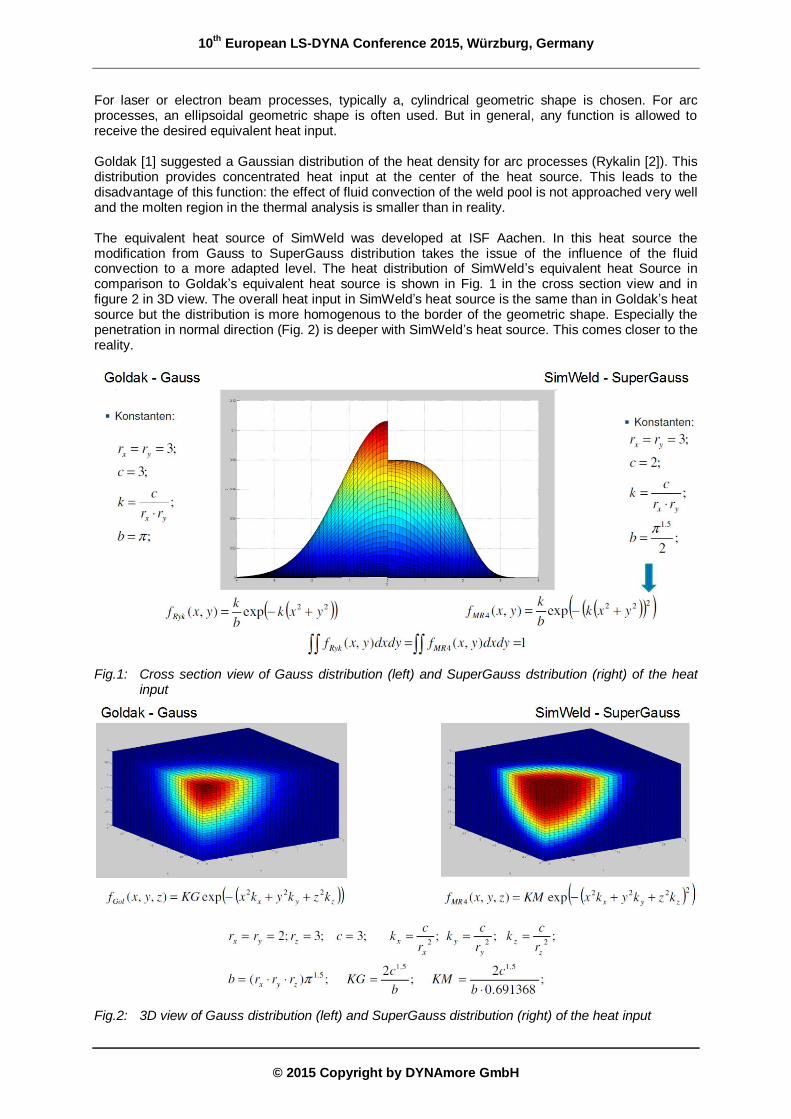
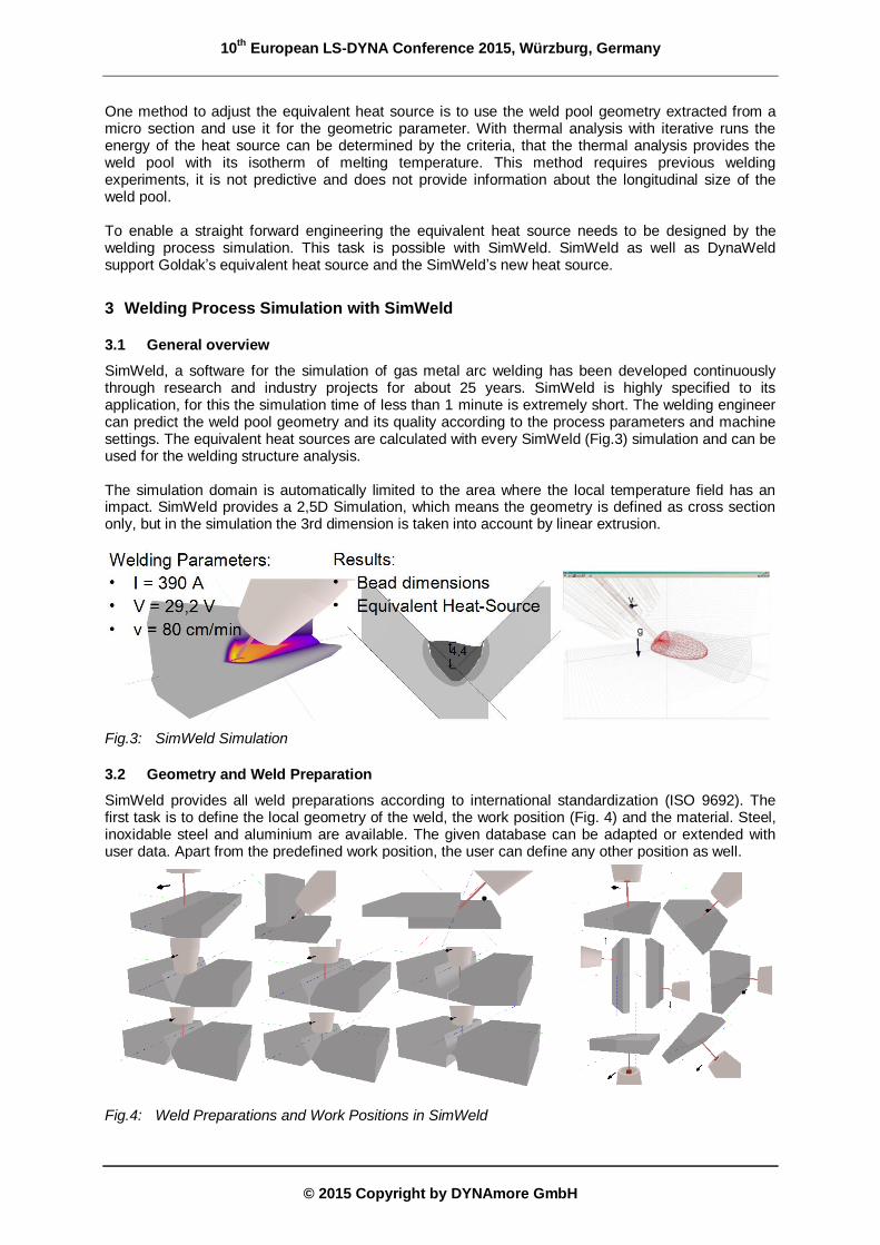
For laser or electron beam processes, typically a, cylindrical geometric shape is chosen. For arc processes, an ellipsoidal geometric shape is often used. But in general, any function is allowed to receive the desired equivalent heat input. Goldak [1] suggested a Gaussian distribution of the heat density for arc processes (Rykalin [2]). This distribution provides concentrated heat input at the center of the heat source. This leads to the disadvantage of this function: the effect of fluid convection of the weld pool is not approached very well and the molten region in the thermal analysis is smaller than in reality. The equivalent heat source of SimWeld was developed at ISF Aachen. In this heat source the modification from Gauss to SuperGauss distribution takes the issue of the influence of the fluid convection to a more adapted level. The heat distribution of SimWeld’s equivalent heat Source in comparison to Goldak’s equivalent heat source is shown in Fig. 1 in the cross section view and in figure 2 in 3D view. The overall heat input in SimWeld’s heat source is the same than in Goldak’s heat source but the distribution is more homogenous to the border of the geometric shape. Especially the penetration in normal direction (Fig. 2) is deeper with SimWeld’s heat source. This comes closer to the reality.
Fig.1: Cross section view of Gauss distribution (left) and SuperGauss dstribution (right) of the heat input
Fig.2: 3D view of Gauss distribution (left) and SuperGauss distribution (right) of the heat input
10th
European LS-DYNA Conference 2015, Würzburg, Germany
One method to adjust the equivalent heat source is to use the weld pool geometry extracted from a micro section and use it for the geometric parameter. With thermal analysis with iterative runs the energy of the heat source can be determined by the criteria, that the thermal analysis provides the weld pool with its isotherm of melting temperature. This method requires previous welding experiments, it is not predictive and does not provide information about the longitudinal size of the weld pool. To enable a straight forward engineering the equivalent heat source needs to be designed by the welding process simulation. This task is possible with SimWeld. SimWeld as well as DynaWeld support Goldak’s equivalent heat source and the SimWeld’s new heat source.
3 Welding Process Simulation with SimWeld
3.1 General overview
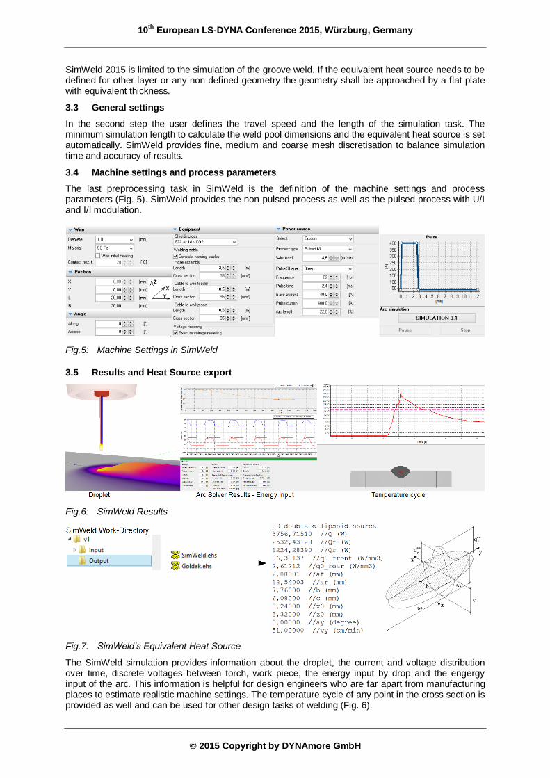
SimWeld, a software for the simulation of gas metal arc welding has been developed continuously through research and industry projects for about 25 years. SimWeld is highly specified to its application, for this the simulation time of less than 1 minute is extremely short. The welding engineer can predict the weld pool geometry and its quality according to the process parameters and machine settings. The equivalent heat sources are calculated with every SimWeld (Fig.3) simulation and can be used for the welding structure analysis. The simulation domain is automatically limited to the area where the local temperature field has an impact. SimWeld provides a 2,5D Simulation, which means the geometry is defined as cross section only, but in the simulation the 3rd dimension is taken into account by linear extrusion.
Fig.3: SimWeld Simulation
3.2 Geometry and Weld Preparation
SimWeld provides all weld preparations according to international standardization (ISO 9692). The first task is to define the local geometry of the weld, the work position (Fig. 4) and the material. Steel, inoxidable steel and aluminium are available. The given database can be adapted or extended with user data. Apart from the predefined work position, the user can define any other position as well.
Fig.4: Weld Preparations and Work Positions in SimWeld
10th
European LS-DYNA Conference 2015, Würzburg, Germany
SimWeld 2015 is limited to the simulation of the groove weld. If the equivalent heat source needs to be defined for other layer or any non defined geometry the geometry shall be approached by a flat plate with equivalent thickness.
3.3 General settings
In the second step the user defines the travel speed and the length of the simulation task. The minimum simulation length to calculate the weld pool dimensions and the equivalent heat source is set automatically. SimWeld provides fine, medium and coarse mesh discretisation to balance simulation time and accuracy of results.
3.4 Machine settings and process parameters
The last preprocessing task in SimWeld is the definition of the machine settings and process parameters (Fig. 5). SimWeld provides the non-pulsed process as well as the pulsed process with U/I and I/I modulation.
Fig.5: Machine Settings in SimWeld
3.5 Results and Heat Source export
Fig.6: SimWeld Results
Fig.7: SimWeld’s Equivalent Heat Source
The SimWeld simulation provides information about the droplet, the current and voltage distribution over time, discrete voltages between torch, work piece, the energy input by drop and the engergy input of the arc. This information is helpful for design engineers who are far apart from manufacturing places to estimate realistic machine settings. The temperature cycle of any point in the cross section is provided as well and can be used for other design tasks of welding (Fig. 6).
10th
European LS-DYNA Conference 2015, Würzburg, Germany
The parameters of the equivalent heat sources, Goldak’s heat source and the SimWeld’s new heat source, are exported to ascii-files in the output directory of SimWeld’s work directory (Fig. 7).
4 DynaWeld - Setup Input deck for Welding Structure Simulation with LS-DYNA
4.1 General overview
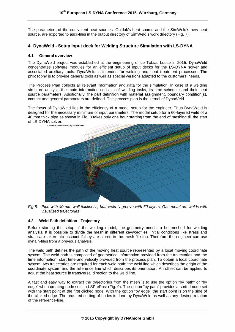
The DynaWeld project was established at the engineering office Tobias Loose in 2015. DynaWeld concentrates software modules for an efficient setup of input decks for the LS-DYNA solver and associated auxiliary tools. DynaWeld is intended for welding and heat treatment processes. The philosophy is to provide general tools as well as special versions adapted to the customers’ needs. The Process Plan collects all relevant information and data for the simulation. In case of a welding structure analysis the main information consists of welding tasks, its time schedule and their heat source parameters. Additionally, the part definition with material assignment, boundary condition(s), contact and general parameters are defined. This procces plan is the kernel of DynaWeld. The focus of DynaWeld lies in the efficiency of a model setup for the engineer. Thus DynaWeld is designed for the necessary minimum of input parameters. The model setup for a 60-layered weld of a 40 mm thick pipe as shown in Fig. 8 takes only one hour starting from the end of meshing till the start of LS-DYNA solver.
Fig.8: Pipe with 40 mm wall thickness, butt-weld U-groove with 60 layers. Gas metal arc welds with visualized trajectories
4.2 Weld Path definition - Trajectory
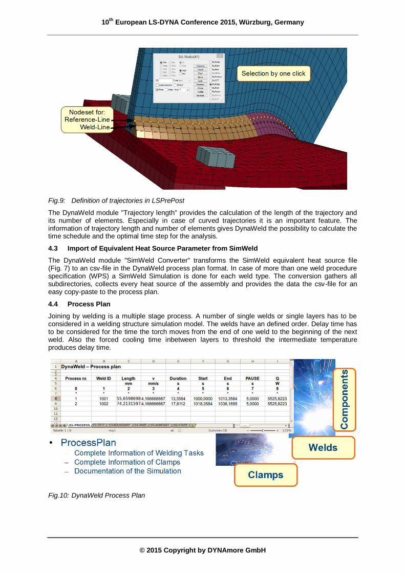
Before starting the setup of the welding model, the geometry needs to be meshed for welding analysis. It is possible to divide the mesh in different keywordfiles. Initial conditions like stress and strain are taken into account if they are stored in the mesh file too. Therefore the engineer can use dynain-files from a previous analysis. The weld path defines the path of the moving heat source represented by a local moving coordinate system. The weld path is composed of geometrical information provided from the trajectories and the time information, start time and velocity provided from the process plan. To obtain a local coordinate system, two trajectories are required for each weld path: the weld line which describes the origin of the coordinate system and the reference line which describes its orientation. An offset can be applied to adjust the heat source in transversal direction to the weld line. A fast and easy way to extract the trajectories from the mesh is to use the option "by path" or "by edge" when creating node sets in LSPrePost (Fig. 9). The option "by path" provides a sorted node set with the start point at the first clicked node. With the option "by edge" the start point is on the side of the clicked edge. The required sorting of nodes is done by DynaWeld as well as any desired rotation of the reference-line.
10th
European LS-DYNA Conference 2015, Würzburg, Germany
The DynaWeld module "Trajectory length" provides the calculation of the length of the trajectory and its number of elements. Especially in case of curved trajectories it is an important feature. The information of trajectory length and number of elements gives DynaWeld the possibility to calculate the time schedule and the optimal time step for the analysis.
4.3 Import of Equivalent Heat Source Parameter from SimWeld
The DynaWeld module "SimWeld Converter" transforms the SimWeld equivalent heat source file (Fig. 7) to an csv-file in the DynaWeld process plan format. In case of more than one weld procedure specification (WPS) a SimWeld Simulation is done for each weld type. The conversion gathers all subdirectories, collects every heat source of the assembly and provides the data the csv-file for an easy copy-paste to the process plan.
4.4 Process Plan
Joining by welding is a multiple stage process. A number of single welds or single layers has to be considered in a welding structure simulation model. The welds have an defined order. Delay time has to be considered for the time the torch moves from the end of one weld to the beginning of the next weld. Also the forced cooling time inbetween layers to threshold the intermediate temperature produces delay time.
Fig.10: DynaWeld Process Plan
10th
European LS-DYNA Conference 2015, Würzburg, Germany
The heart of the simulation model is the process plan. A spreadsheet file is commonly used to collect this data. DynaWelds benefit is the use of this spreadsheet file as an input source which saves work time. With the table PROCESS, TIME, BOUNDARY, PART, CONTACT and START all relevant data of the simulation model are collected in this file (Fig 9). Because of copy-paste function the input of data is quick even if a lot of welds have to be defined.
4.5 Input deck generation and Check
The input deck generation is splitted in the tasks for each sheet of the process plan. This aims the possibility of separately update the input deck. For example only one part of the definition can be updated without any touch of the rest of the input. The input deck is readable from any Preprocessor for LS-DYNA. Another benefit is that DynaWeld provides a complement of the input deck by the user. This means no limitation exists and the whole capability of LS-DYNA can be used. DynaWeld generates special keyword files for the input check. Fig. 10 shows the check for the trajectories.
Fig.11: Visualisation of trajectories
4.6 Performance Analysis
Welding structure analysis is generally fighting against simulation time. Performance of welding models is a big issue. An unfortunate choice of solver settings or time stepping can lead to significant extension of simulation time. The DynaWeld module "Performance Analysis" parses the LOG-file of LS-DYNA and extracts the relevant data. The example in Fig. 11 clarifies the influence of a different time step and the accuracy settings. If the result quality of the different variants fit the requirement it is obvious that the green variant is the best choice.
Fig.12: Performance Analysis by DynaWeld
10th
European LS-DYNA Conference 2015, Würzburg, Germany
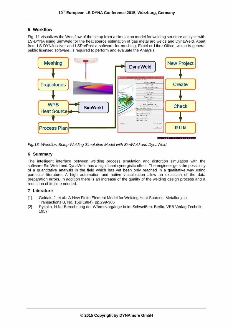
Fig. 11 visualizes the Workflow of the setup from a simulation model for welding structure analysis with LS-DYNA using SimWeld for the heat source estimation of gas metal arc welds and DynaWeld. Apart from LS-DYNA solver and LSPrePost a software for meshing, Excel or Libre Office, which is general public licensed software, is required to perform and evaluate the Analysis.
Fig.13: Workflow Setup Welding Simulation Model with SimWeld and DynaWeld
6 Summary
The intelligent interface between welding process simulation and distortion simulation with the software SimWeld and DynaWeld has a significant synergistic effect. The engineer gets the possibility of a quantitative analysis in the field which has yet been only reached in a qualitative way using particular literature. A high automation and native visualization allow an exclusion of the data preparation errors. In addition there is an increase of the quality of the welding design process and a reduction of its time needed.
7 Literature
[1] Goldak, J. et al.: A New Finite Element Model for Welding Heat Sources. Metallurgical Transactions B, No. 15B(1984), pp.299-305
[2] Rykalin, N.N.: Berechnung der Wärmevorgänge beim Schweißen. Berlin, VEB Verlag Technik 1957