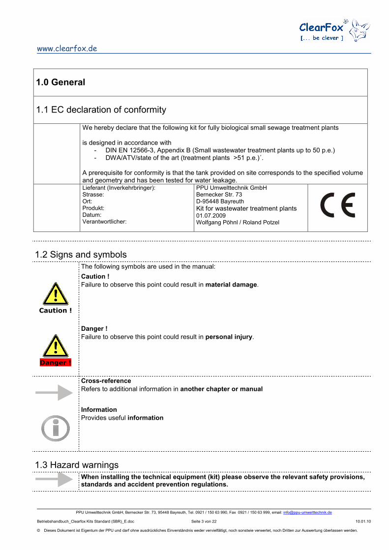
We hereby declare that the following kit for fully biological small sewage treatment plants is designed in accordance with
- DIN EN 12566-3, Appendix B (Small wastewater treatment plants up to 50 p.e.) - DWA/ATV/state of the art (treatment plants >51 p.e.)´.
A prerequisite for conformity is that the tank provided on site corresponds to the specified volume and geometry and has been tested for water leakage.
Congratulations on your purchase of a high-quality, innovative product.
In order to prevent any damage we would ask you in particular to read through this manual completely before putting the plant into operation.
We reserve the right to make changes to the technical specifications.
Please check the product on delivery for any signs of damage that may have occurred during transport. In this event, you must notify your dealer or PPU Umwelttechnik GmbH in writing immediately.
1.5 Warrenty
We would refer you to the General Terms and Conditions of PPU Umwelttechnik GmbH (www.ppu-umwelttechnik.de), and to those of your dealer.
2.0 Product discription
2.1 Use
Caution !
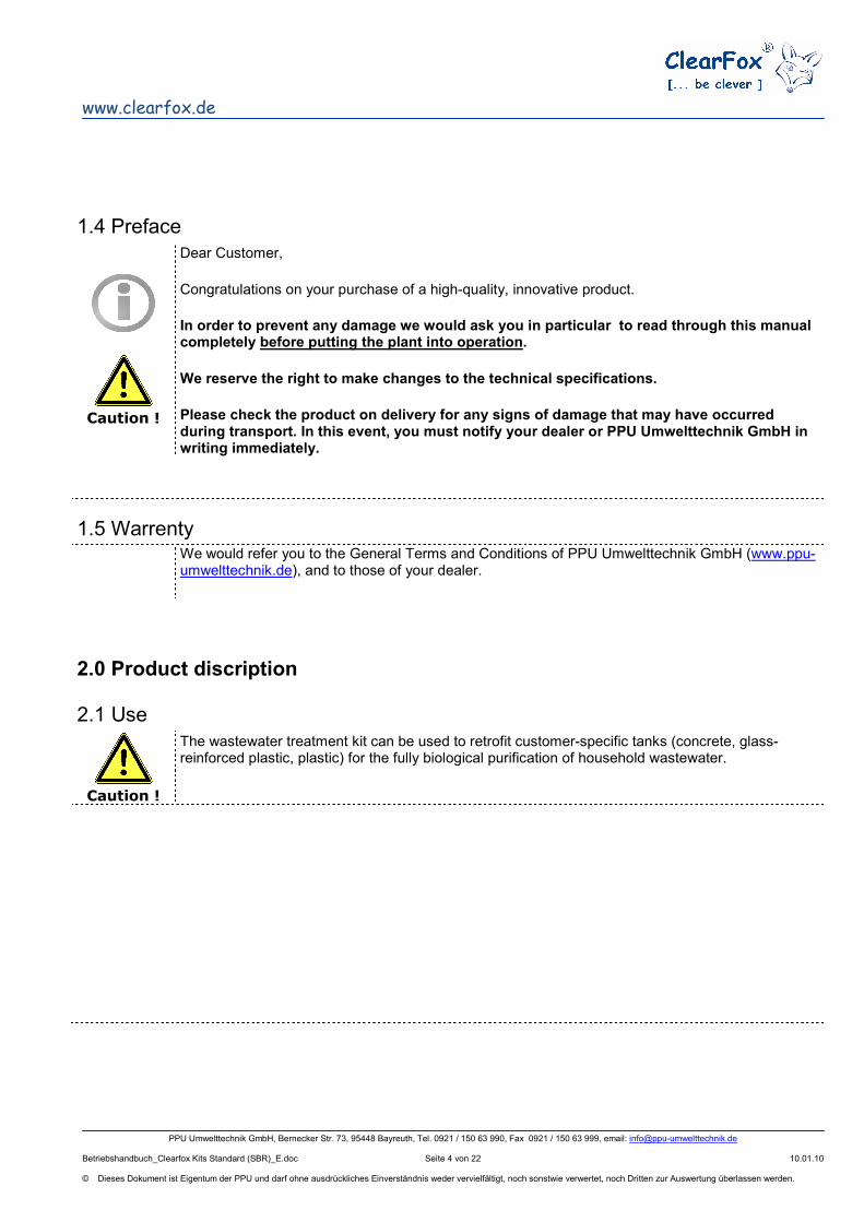
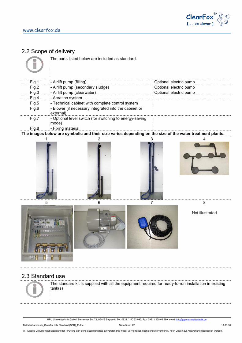
The wastewater treatment kit can be used to retrofit customer-specific tanks (concrete, glass-reinforced plastic, plastic) for the fully biological purification of household wastewater.
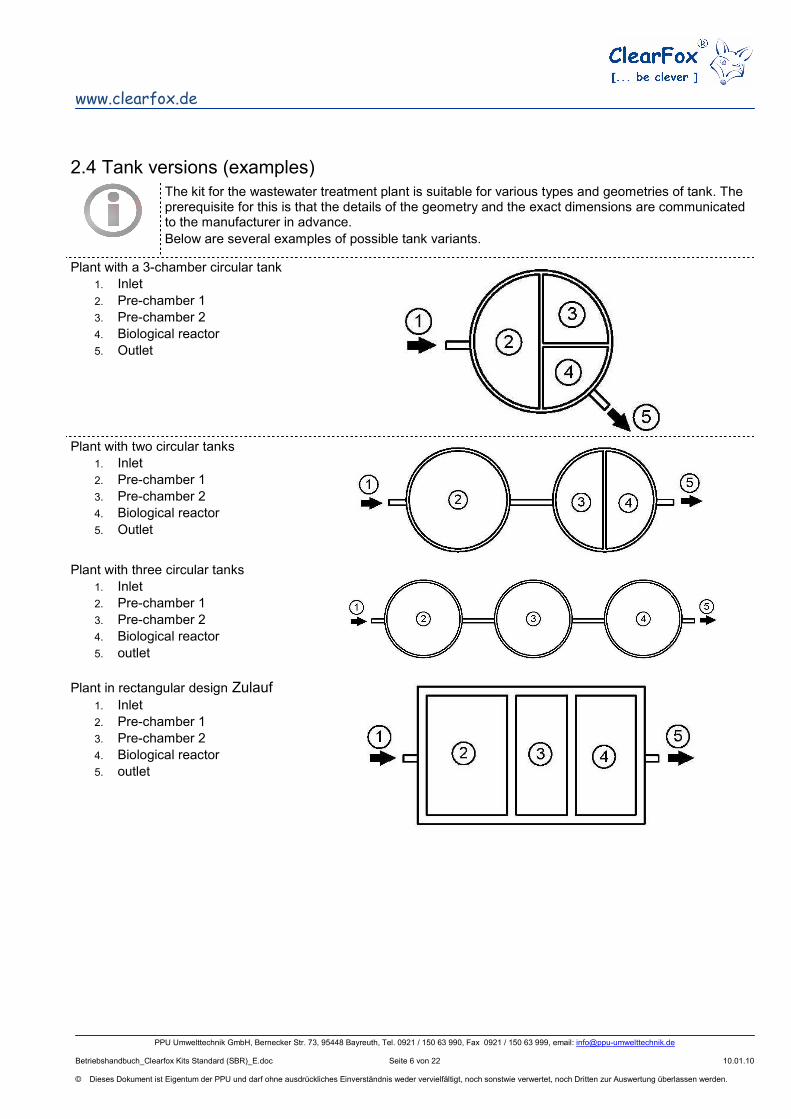
The kit for the wastewater treatment plant is suitable for various types and geometries of tank. The prerequisite for this is that the details of the geometry and the exact dimensions are communicated to the manufacturer in advance.
Below are several examples of possible tank variants.
The following work must be completed prior to installation of the treatment plant and the following circumstances must exist (points 1-4 can be ignored when complete treatment plants are supplied in plastic tanks):
1. The tank must be watertight and comply with the relevant standard. 2. The tank must have the required volume. 3. The chamber for activation (SBR reactor) must be made watertight.
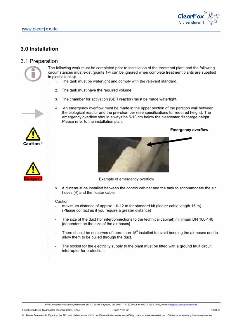
4. An emergency overflow must be made in the upper section of the partition wall between
the biological reactor and the pre-chamber (see specifications for required height). The emergency overflow should always be 5-10 cm below the clearwater discharge height. Please refer to the installation plan.
Example of emergency overflow
5. A duct must be installed between the control cabinet and the tank to accommodate the air hoses (4) and the floater cable.
Caution - maximum distance of approx. 10-12 m for standard kit (floater cable length 15 m)
(Please contact us if you require a greater distance) - The size of the duct (for interconnections to the technical cabinet) minimum DN 100-140
[dependent on the size of the air hoses]
- There should be no curves of more than 150 installed to avoid bending the air hoses and to
allow them to be pulled through the duct.
- The socket for the electricity supply to the plant must be fitted with a ground fault circuit interrupter for protection.
Must be performed before the tank is filled with water or wastewater.
Installation / de-installation can be dangerous and should only be performed by a qualified person.
Do not climb into an unventilated tank (chamber) – Danger to life Please observe the specialist provisions of the occupational safety organisation (Berufsgenossenschaft).
When touching parts in the tank after operation has commenced please observe hygiene precautions (protective gloves, protective clothing, disinfectant, protective inoculation) – Danger of infection
Incorrect or faulty installation impairs the function
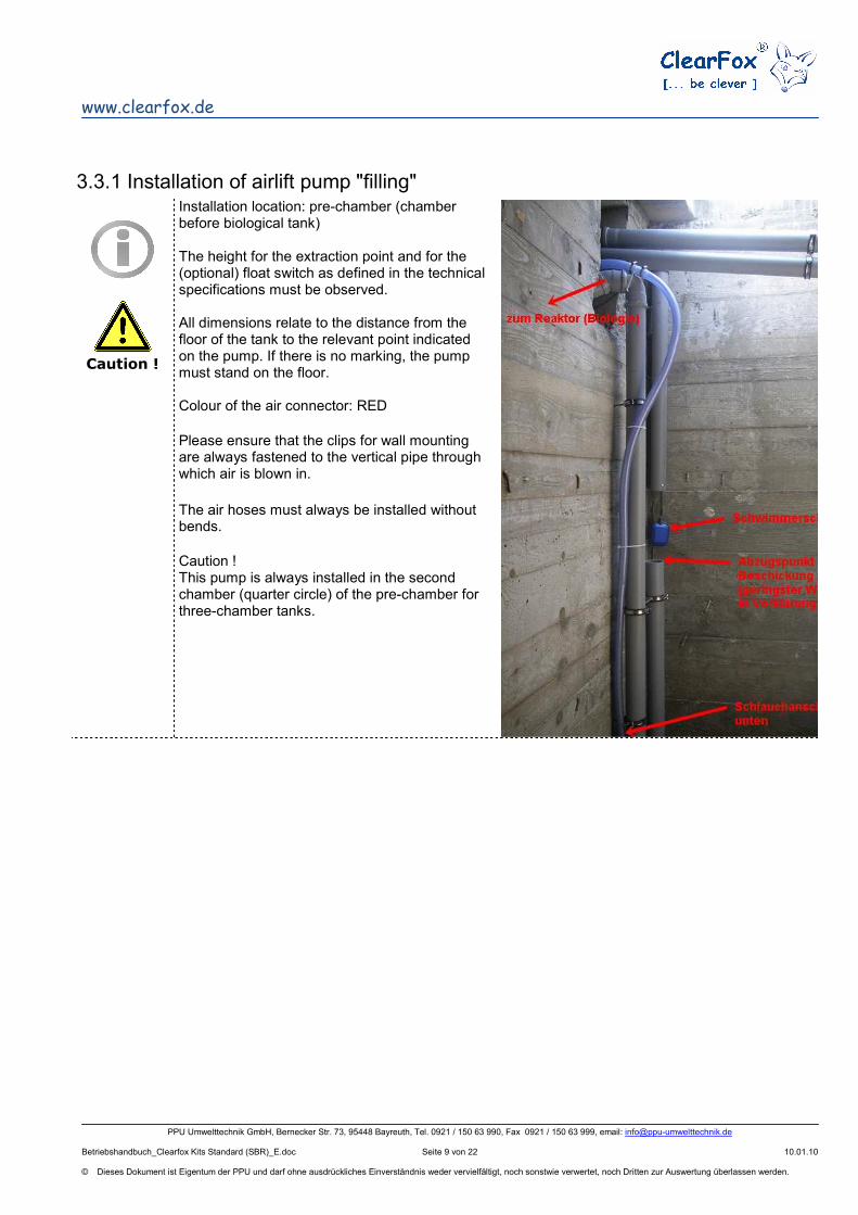
Installation location: pre-chamber (chamber before biological tank) The height for the extraction point and for the (optional) float switch as defined in the technical specifications must be observed. All dimensions relate to the distance from the floor of the tank to the relevant point indicated on the pump. If there is no marking, the pump must stand on the floor. Colour of the air connector: RED
Please ensure that the clips for wall mounting are always fastened to the vertical pipe through which air is blown in.
The air hoses must always be installed without bends.
Caution ! This pump is always installed in the second chamber (quarter circle) of the pre-chamber for three-chamber tanks.
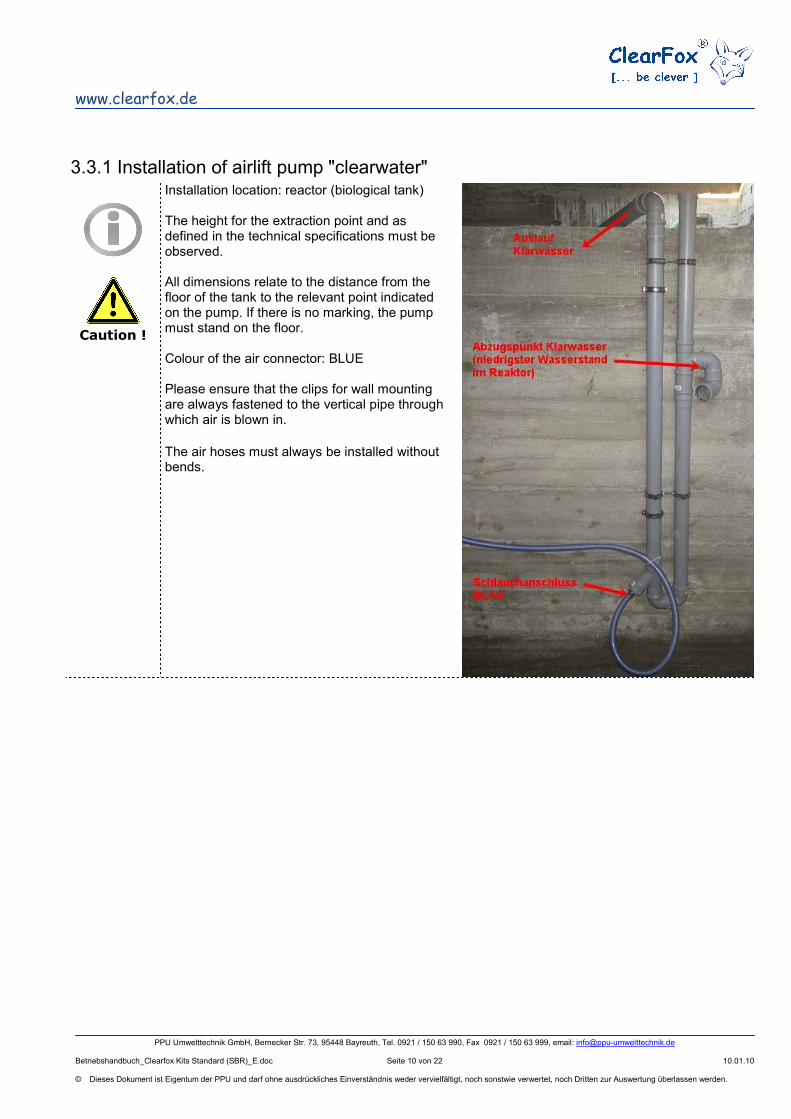
Installation location: reactor (biological tank) The height for the extraction point and as defined in the technical specifications must be observed. All dimensions relate to the distance from the floor of the tank to the relevant point indicated on the pump. If there is no marking, the pump must stand on the floor. Colour of the air connector: BLUE Please ensure that the clips for wall mounting are always fastened to the vertical pipe through which air is blown in.
The air hoses must always be installed without bends.
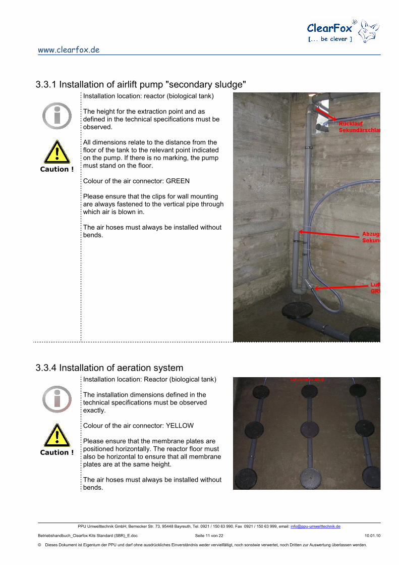
3.3.1 Installation of airlift pump "secondary sludge"
Caution !
Installation location: reactor (biological tank) The height for the extraction point and as defined in the technical specifications must be observed. All dimensions relate to the distance from the floor of the tank to the relevant point indicated on the pump. If there is no marking, the pump must stand on the floor. Colour of the air connector: GREEN Please ensure that the clips for wall mounting are always fastened to the vertical pipe through which air is blown in. The air hoses must always be installed without bends.
3.3.4 Installation of aeration system
Caution !
Installation location: Reactor (biological tank) The installation dimensions defined in the technical specifications must be observed exactly. Colour of the air connector: YELLOW Please ensure that the membrane plates are positioned horizontally. The reactor floor must also be horizontal to ensure that all membrane plates are at the same height. The air hoses must always be installed without bends.
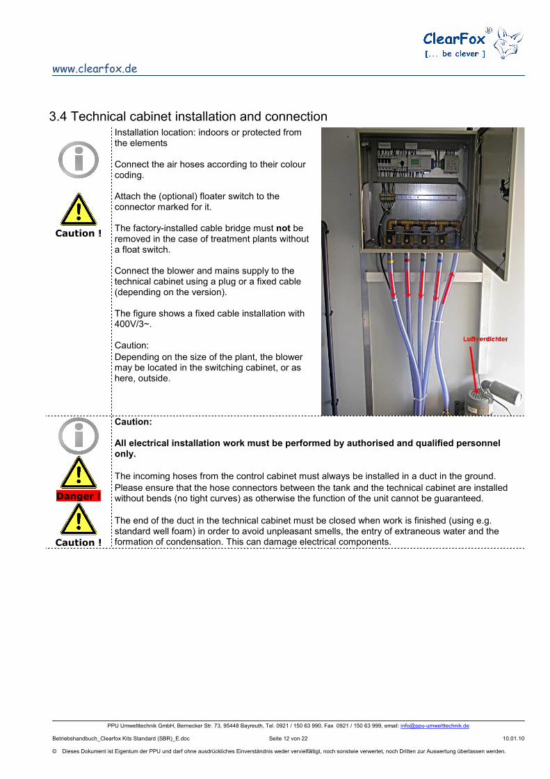
Installation location: indoors or protected from the elements Connect the air hoses according to their colour coding. Attach the (optional) floater switch to the connector marked for it. The factory-installed cable bridge must not be removed in the case of treatment plants without a float switch. Connect the blower and mains supply to the technical cabinet using a plug or a fixed cable (depending on the version). The figure shows a fixed cable installation with 400V/3~. Caution:
Depending on the size of the plant, the blower may be located in the switching cabinet, or as here, outside.
Danger !
Caution !
Caution: All electrical installation work must be performed by authorised and qualified personnel only.
The incoming hoses from the control cabinet must always be installed in a duct in the ground.
Please ensure that the hose connectors between the tank and the technical cabinet are installed without bends (no tight curves) as otherwise the function of the unit cannot be guaranteed.
The end of the duct in the technical cabinet must be closed when work is finished (using e.g. standard well foam) in order to avoid unpleasant smells, the entry of extraneous water and the formation of condensation. This can damage electrical components.
1. all machinery (airlifts / any electrical pumps) are connected correctly. 2. the height of the extraction points is correct. 3. the emergency overflow is present 4. the tank and the activation chamber (SBR reactor) are water-tight (perform leakage checks) 5. sufficient aeration / ventilation is present (e.g. whether a roof vent is present). 6. fill the SBR reactor with water to at least 30 cm above the membrane aerator (plate aerator).
The performance of the airlift pumps can only be tested correctly if the water is at the maximum level in all three chambers.
7. Please ensure during connection work that all cables and hoses are long enough for the units to be removed from the tanks without any problems.
8. The rotational direction of the blower and of an electrical pumps (on relevant with 400 V/3~ ) must be tested before the plant goes into operation. All pumps can be activated from the control unit manually (please refer to the description of the control unit and its menu system).
4.2 Putting the control unit into operation
Caution !
The tank should be filled with water before the following activities are performed.
Caution:
Fill all tanks with the same level of water
Please refer to the operating instructions for the control unit
The ClearFox® works as an activated sludge treatment plant with SBR.
The treatment plant has an upstream coarse separator that serves as storage for the primary
and secondary sludge and to buffer the inlet water. Sludge filling and clearwater extraction are
effected by means of airlift pumps. The plant's control system recognises four main states in the
normal cycle.
Normal cycle: Filling phase – the filling airlift pump conveys water from the pre-chamber to the reactor. Purification phase – the wastewater is circulated in the SBR reactor using air fed in through the membrane plate(s) and the bacteria are supplied with oxygen. This occurs at intervals controlled by the computer. Settling phase – the wastewater separates, with the sludge material sinking (sedimentation) and the cleaned water remaining at the top (a layer of clearwater forms). Secondary sludge extraction – the secondary sludge (excess sludge) from the biological process is isolated and to a small degree pumped back into the pre-chamber. Clearwater extraction – following the settling phase, the clearwater pump conveys the clearwater that remains above the "clearwater" discharge point to the plant outlet, lowering the water level in the reactor. The main states listed above are together called the cycle. A complete purification cycle takes approx. 7 hours. Energy-saving cycle (optional – level switch required)
The purification programme continues running unabated, however with a shortened aeration phase, which reduces the amount of energy required. Depending on the inlet quantity to the pre-chamber, the programme then decides fully automatically whether the energy-saving cycle should continue or whether it should switch back to normal operating mode.
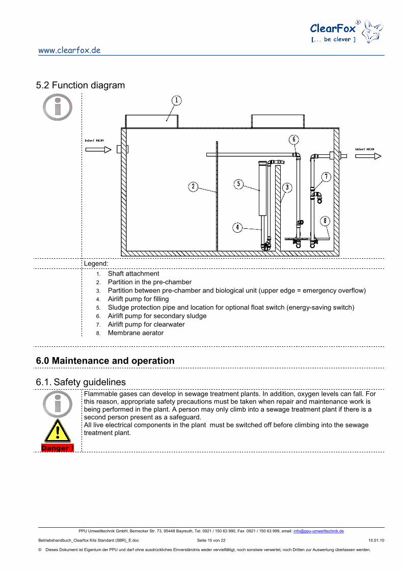
3. Partition between pre-chamber and biological unit (upper edge = emergency overflow)
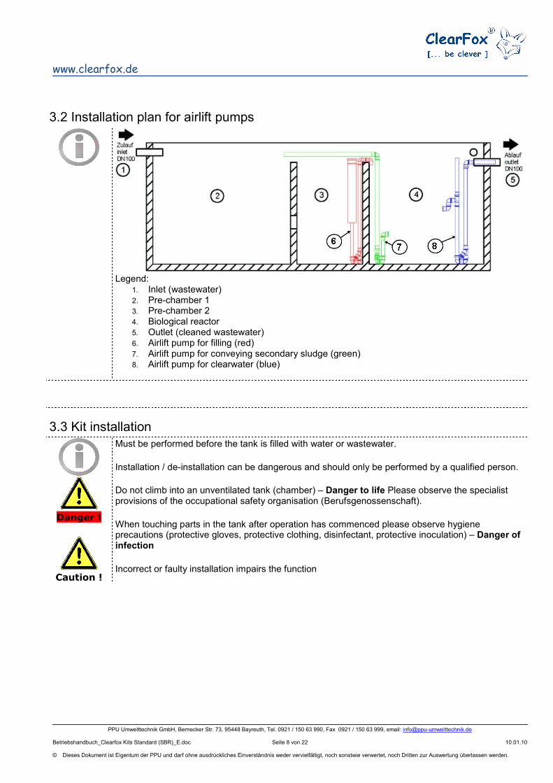
4. Airlift pump for filling
5. Sludge protection pipe and location for optional float switch (energy-saving switch)
6. Airlift pump for secondary sludge
7. Airlift pump for clearwater
8. Membrane aerator
6.0 Maintenance and operation 6.1. Safety guidelines
Danger !
Flammable gases can develop in sewage treatment plants. In addition, oxygen levels can fall. For this reason, appropriate safety precautions must be taken when repair and maintenance work is being performed in the plant. A person may only climb into a sewage treatment plant if there is a second person present as a safeguard. All live electrical components in the plant must be switched off before climbing into the sewage treatment plant.
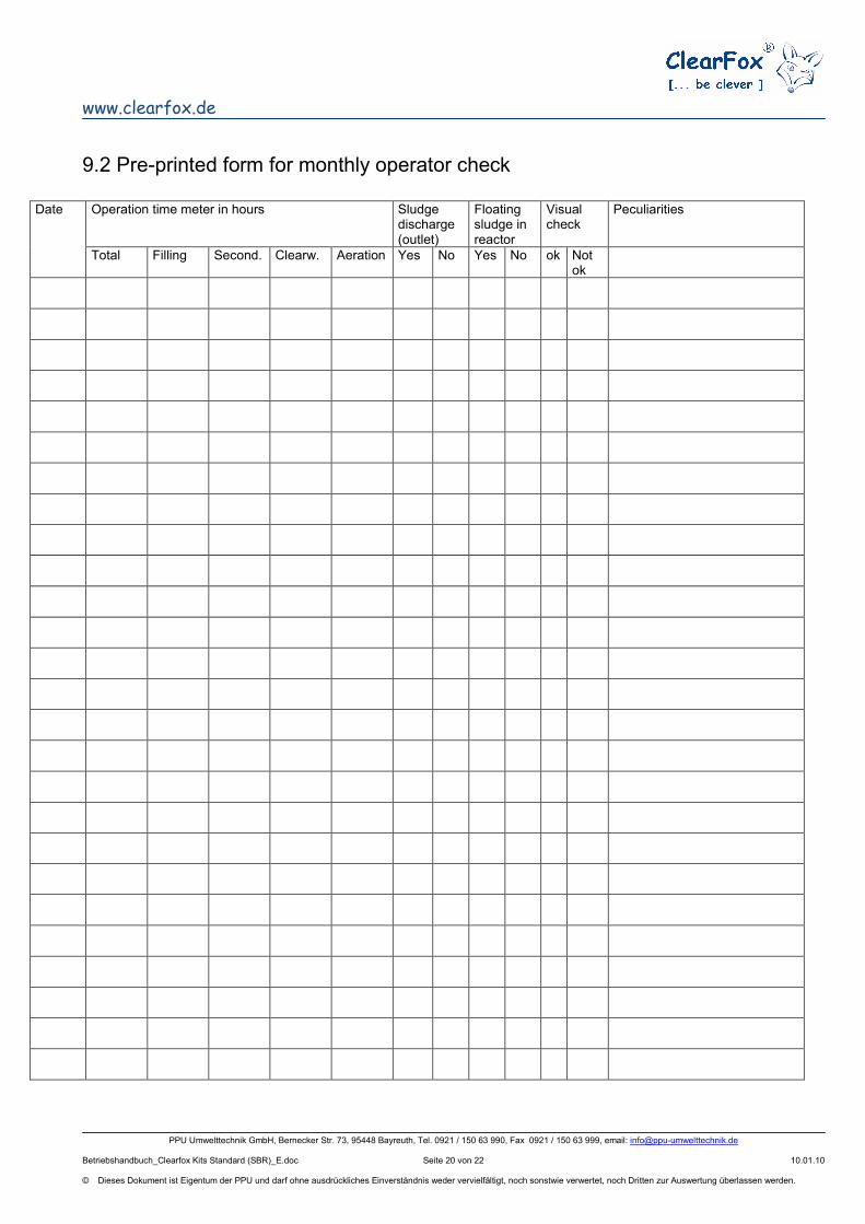
The owner must operate the plant or must contract a third party to operate it (operator). Daily check: Perform function check. If there is any disruption in operation encountered, it must be resolved immediately by the operator or by a specially trained person instructed to do so by the operator. Monthly check: In accordance with the form for monthly operator check
- Note the number of hours of operation of the blower (indicated in the display alternating with the display of the relevant programme step)
- Check for sludge overflow in the outlet - Check for floating sludge in the reactor (if present, scoop off and return to the pre-chamber) - Visual check for mechanical damage and fine bubbles in aeration process - Check to ensure that the float switch (if present) works, and clean if necessary.
An operations logbook must be kept for all sewage treatment plants. For this, please make a copy of the maintenance checklist (form for the monthly operator check) to be found at the back of this manual. Any disruptions must be recorded in the operations logbook. Maintenance work, sludge extraction, maintenance reports and any other special incidents must also be recorded in the operations logbook. This operations logbook must be presented to the relevant authorities upon request.
6.3 Maintenance
Maintenance is performed several times a year by a maintenance company. The relevant responsible authority prescribes how often maintenance must be performed. The operator is free to choose the maintenance company. The following work must be performed at least twice per year at intervals of around 6 months: a. Inspection of the operations logbook and reading of the operating time meter with
determination of regular operations (target/performance comparison). b. Function check for the mechanical, electrical and other plant equipment that is important for
operations such as: blower, removal pump, if necessary excess sludge pump, control unit, float switch.
c. Maintenance of mechanical equipment
d. Adjustment of optimum operating values, e,g, oxygen supply (∼ 2 mg/l), sludge volume (300–500 ml/l).
e. Determination of the sludge level in the sludge storage tank and if necessary organisation of sludge removal when the sludge reaches half the water level in the sludge storage tank (pre-chamber). In this case only the tanks upstream from the reactor (SBR) should be emptied and then refilled with water.
f. Performance of general cleaning tasks, e.g.: removal of deposits and foreign bodies g. inspection of the structural condition of the plant, e.g.: corrosion, accessibility, ventilation,
screw connections, hoses. h. The maintenance work performed must be recorded in the operations logbook. The following tests must be performed in the course of maintenance
Caution
Samples can only be taken from the outlet of an SBR treatment plant during the
extraction pump process or from a separate sampling device.
i. Test of a random sample from the outlet for - temperature - pH-value - settleable substances - transparency - BOD5 (at least every 2nd maintenance date)
j. Tests in the activation tank:
- oxygen concentration - proportion of sludge volume - sludge index - dry matter in the activated sludge
The results and the work performed must be recorded in the maintenance report. The maintenance report must be submitted to the operator. The operator must include the maintenance report in the operations logbook. The maintenance report must be presented to the relevant authorities upon request.
Caution !
Sludge removal may only take place in the pre-chamber
7.0 What to do when disruptions occur?
Disruptions such as power outage are indicated by a warning, and an acoustic signal is emitted. Please remain calm - a disruption is not a catastrophe. Should you find that you are unable to resolve the disruption on your own, please call your maintenance service company. You should do this immediately in order for the treatment plant to resume wastewater purification. Please refer to the "Control system operating manual" for more information on how to deal with warnings and other messages.
The disruption warning requires a battery to be installed in the control unit.
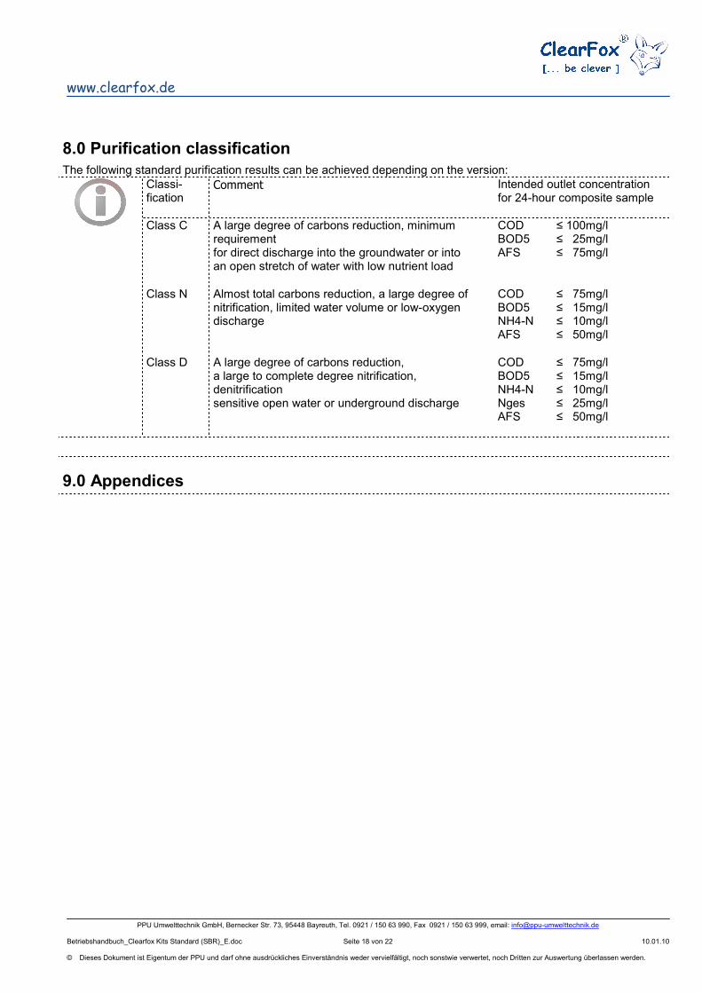
The following standard purification results can be achieved depending on the version:
Classi-fication
Comment Intended outlet concentration for 24-hour composite sample
Class C A large degree of carbons reduction, minimum requirement for direct discharge into the groundwater or into an open stretch of water with low nutrient load
COD BOD5 AFS
≤ 100mg/l ≤ 25mg/l ≤ 75mg/l
Class N Almost total carbons reduction, a large degree of nitrification, limited water volume or low-oxygen discharge
COD BOD5 NH4-N AFS
≤ 75mg/l ≤ 15mg/l ≤ 10mg/l ≤ 50mg/l
Class D A large degree of carbons reduction, a large to complete degree nitrification, denitrification sensitive open water or underground discharge
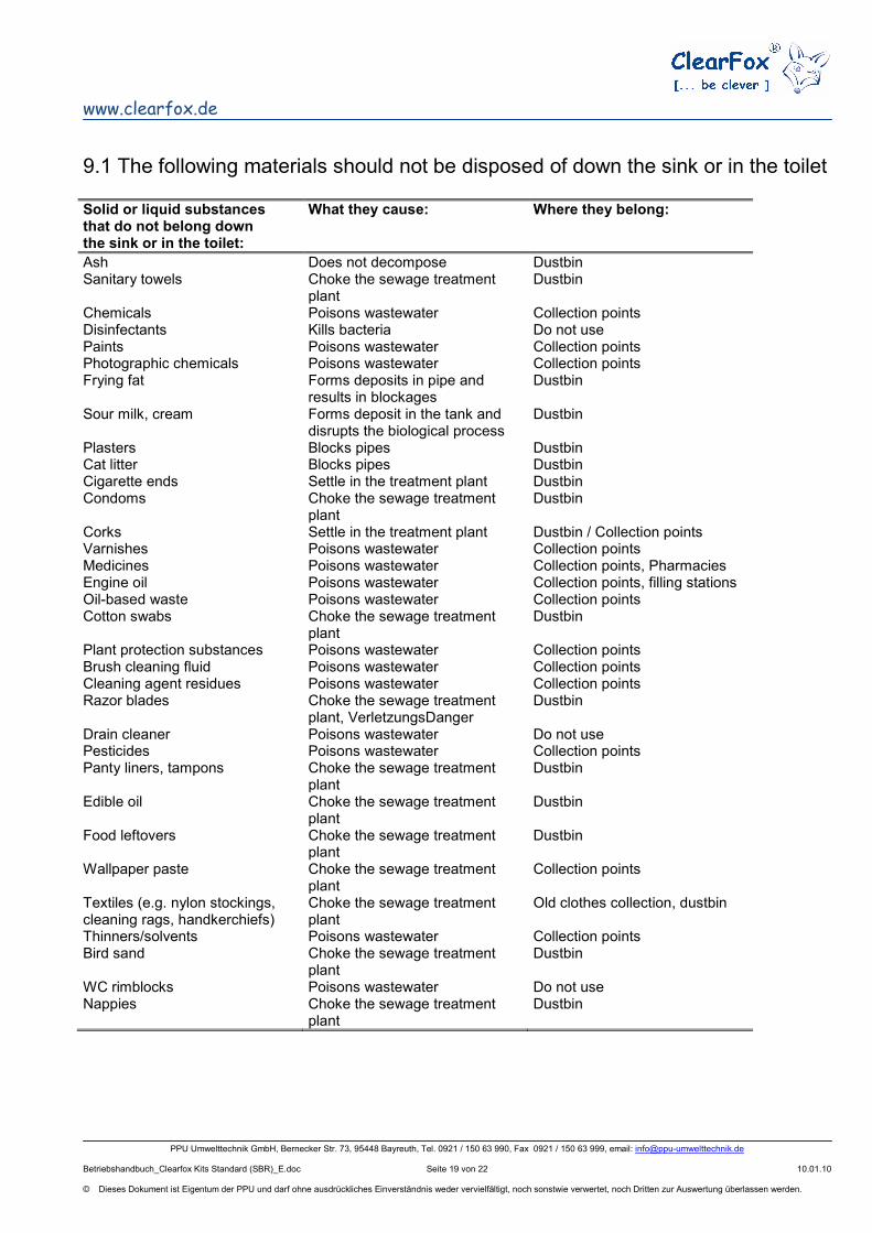
9.1 The following materials should not be disposed of down the sink or in the toilet
Solid or liquid substances that do not belong down the sink or in the toilet:
What they cause: Where they belong:
Ash Does not decompose Dustbin Sanitary towels Choke the sewage treatment
plant Dustbin
Chemicals Poisons wastewater Collection points Disinfectants Kills bacteria Do not use Paints Poisons wastewater Collection points Photographic chemicals Poisons wastewater Collection points Frying fat Forms deposits in pipe and
results in blockages Dustbin
Sour milk, cream Forms deposit in the tank and disrupts the biological process
Dustbin
Plasters Blocks pipes Dustbin Cat litter Blocks pipes Dustbin Cigarette ends Settle in the treatment plant Dustbin Condoms Choke the sewage treatment
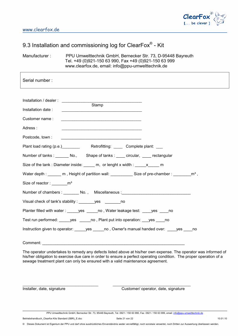
Installation / dealer : ____________________________________ Stamp Installation date : ____________________________________ Customer name : ____________________________________ Adress : ____________________________________ Postcode, town : ____________________________________ Plant load rating (p.e.)________ Retrofitting: ____ Complete plant: ___ Number of tanks : ______ No., Shape of tanks : ____ circular, ____ rectangular Size of the tank : Diameter inside: _____ m, or lenght x width : _____x_____ m Water depth : ______ m , Height of partition wall: __________ Size of pre-chamber : ________m³ , Size of reactor : _______m³ Number of chambers : _______ No. , Miscellaneous :_______________________________ Visual check of tank's stability : _______yes _______no Planter filled with water : _____yes _____no , Water leakage test: ____yes ____no Test run performed: _____yes _____no , Plant put into operation: ___yes ____no Instruction given to operator: _____yes _____no , Owner's manual handed over: ____yes ____no Comment: ________________________________________________________________ The operator undertakes to remedy any defects listed above at his/her own expense. The operator was informed of his/her obligation to exercise due care in order to ensure a perfect operating condition. The proper operation of a sewage treatment plant can only be ensured with a valid maintenance agreement. __________________________________ ___________________________________ Installer, date, signature Customer/ operator, date, signature
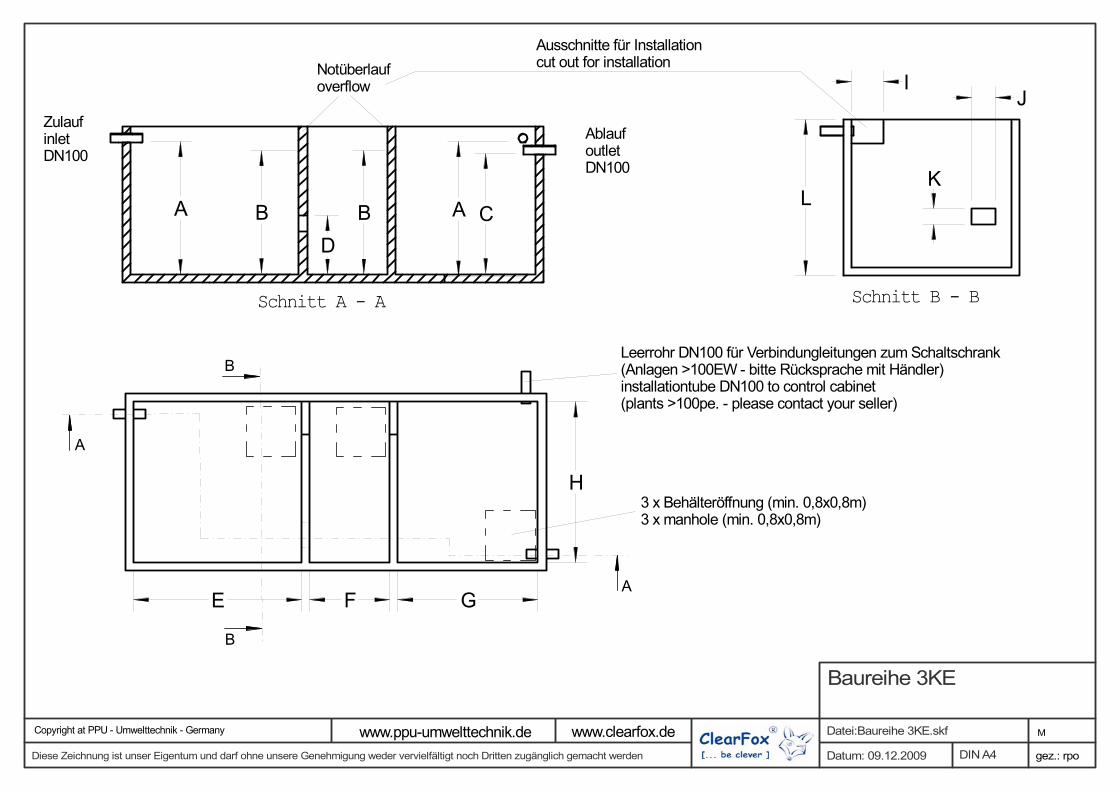
Ausschnitte für Installationcut out for installation
ZulaufinletDN100
AblaufoutletDN100
Leerrohr DN100 für Verbindungleitungen zum Schaltschrank(Anlagen >100EW - bitte Rücksprache mit Händler)installationtube DN100 to control cabinet(plants >100pe. - please contact your seller)
3 x Behälteröffnung (min. 0,8x0,8m)3 x manhole (min. 0,8x0,8m)
gez.: rpo
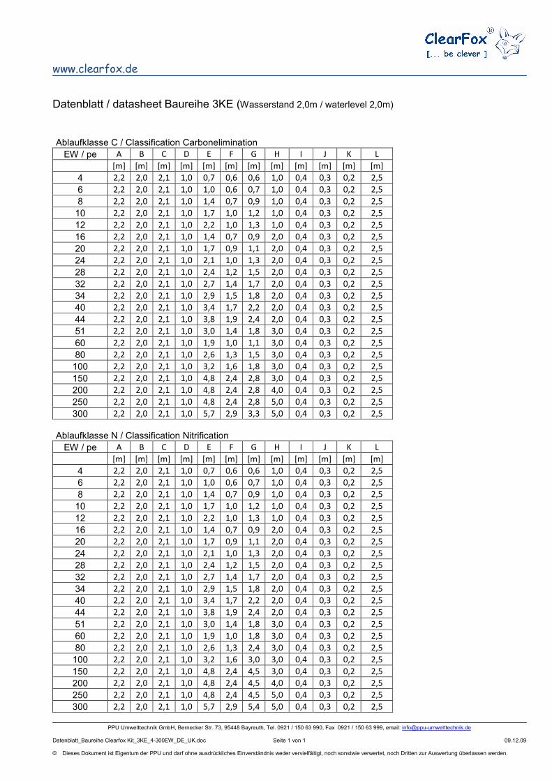
Baureihe 3KE
Datum: 09.12.2009
Datei:Baureihe 3KE.skf M
Diese Zeichnung ist unser Eigentum und darf ohne unsere Genehmigung weder vervielfältigt noch Dritten zugänglich gemacht werden DIN A4
Copyright at PPU - Umwelttechnik - Germany www.ppu-umwelttechnik.de www.clearfox.de


![Neuerwerbungsverzeichnis der Hochschulbibliothek 03/2018 · AR 22480 P295 . Patel, Himanshu ¬[Verfasser]: Characterization and treatment of textile wastewater / Himanshu Patel, R.T.](https://static.unterlagen.site/doc/80x56/5e17a8c26afa994cf95a9fa6/neuerwerbungsverzeichnis-der-hochschulbibliothek-032018-ar-22480-p295-patel.jpg)


