1/7 A 11/05 AWA1230-2022 Montageanweisung Installation Instructions Notice d’installation Istruzioni per il montaggio Instrucciones de montaje Инструкция по монтажу Lebensgefahr durch elektrischen Strom! Nur Elektrofachkräfte und elektrotechnisch unterwiesene Personen dürfen die im Folgen- den beschriebenen Arbeiten ausführen. Electric current! Danger to life! Only skilled or instructed persons may carry out the following operations. Tension électrique dangereuse ! Seules les personnes qualifiées et averties doivent exécuter les travaux ci-après. Tensione elettrica: Pericolo di morte! Solo persone abilitate e qualificate possono eseguire le operazioni di seguito riportate. ¡Corriente eléctrica! ¡Peligro de muerte! El trabajo a continuación descrito debe ser realizado por personas cualificadas y advertidas. Электрический ток! Опасно для жизни! Только специалисты или проинструктированные лица могут выполнять следующие операции. NZMN(H)(L)4(-4)-AE(VE)(ME)... N4(-4)-... +NZM4(-4)-XT NZMN(H)(L)4-AE(VE)...-AP N4-...-AP NZMN(H)(L)4-AE(AEF)...-NA NZMN(H)(L)4-VE(VEF)...-NA N(S)4-...-NA (UL/CSA models) M10 metric size hardware 90˚ 90˚ 90˚ 90˚ f 15 100 > 690 V 200 Minimum Clearance space for all models mm inch 15 0.6 100 4 200 8 Ausblasrichtung im Kurzschlussfall Blowout direction in case of a short-circuit Dégagement gazeux en cas de court-circuit. Direzione di estinzione in caso di corto circuito Dirección de salida de los gases en caso de cortocircuito Направление продувки в случае короткого замыкания 29 13 F 20 F 24 13 F 20 F 20 F 25 o 10. 5 F 20 F 24 o 10. 5 13 13 F 50 o 10. 5 F 20 13 a b c d e f 500 o 10.5 f 500 o 10.5 25 F 50 25 29 29 a b c d e F (2 x) 10 x 24 x 1 mm F (2 x) 25 x 10 mm (2 x) 10 x 50 x 1mm (2 x) 50 x 10 mm 4 x 50 – 185 mm 2 4 x AWG 0 – 350 kcmil r XKB r XKM1 r NZM-XKV F (2 x) 10 x 32 x 1 mm F (2 x) 50 x 10 mm 6 x 95 – 240 mm 2 4 x 300 mm 2 r XKM1 4 x AWG 000 – 500 kcmil F (2 x) 10 x 50 x 1 mm 2 x 600 kcmil For Immediate Delivery call KMParts.com at (866) 595-9616
Transcript
A11/05 AWA1230-2022
MontageanweisungInstallation InstructionsNotice d’installationIstruzioni per il montaggio
Instrucciones de montajeИнструкция по монтажу
1/7
Lebensgefahr durch elektrischen Strom!Nur Elektrofachkräfte und elektrotechnisch unterwiesene Personen dürfen die im Folgen-den beschriebenen Arbeiten ausführen.
Electric current! Danger to life!Only skilled or instructed persons may carry out the following operations.
Tension électrique dangereuse !Seules les personnes qualifiées et averties doivent exécuter les travaux ci-après.
Tensione elettrica: Pericolo di morte!Solo persone abilitate e qualificate possono eseguire le operazioni di seguito riportate.
¡Corriente eléctrica! ¡Peligro de muerte!El trabajo a continuación descrito debe ser realizado por personas cualificadas y advertidas.
Электрический ток! Опасно для жизни!Только специалисты или проинструктированные лица могут выполнять следующие операции.
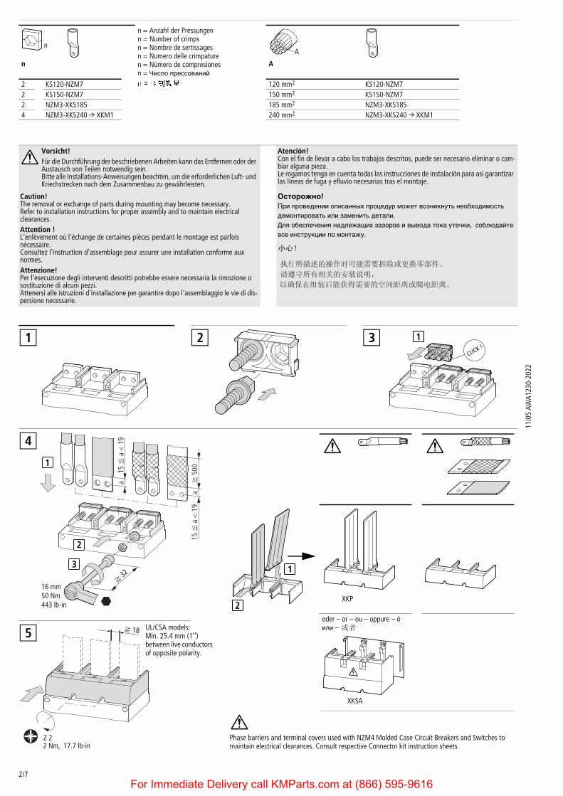
Vorsicht!Für die Durchführung der beschriebenen Arbeiten kann das Entfernen oder der Austausch von Teilen notwendig sein.Bitte alle Installations-Anweisungen beachten, um die erforderlichen Luft- und Kriechstrecken nach dem Zusammenbau zu gewährleisten.
Atención!Con el fin de llevar a cabo los trabajos descritos, puede ser necesario eliminar o cam-biar alguna pieza.Le rogamos tenga en cuenta todas las instrucciones de instalación para así garantizar las líneas de fuga y efluvio necesarias tras el montaje.
Caution!The removal or exchange of parts during mounting may become necessary. Refer to installation instructions for proper assembly and to maintain electricalclearances.Attention !L’enlèvement où l’échange de certaines pièces pendant le montage est parfoisnécessaire.Consultez l’instruction d’assemblage pour assurer une installation conforme auxnormes.Attenzione!Per l'esecuzione degli interventi descritti potrebbe essere necessaria la rimozione o sostituzione di alcuni pezzi. Attenersi alle istruzioni d'installazione per garantire dopo l'assemblaggio le vie di dis-persione necessarie.
Осторожно!При проведении описанных процедур может возникнуть необходимость
демонтировать или заменить детали.
Для обеспечения надлежащих зазоров и вывода тока утечки, соблюдайте
все инструкции по монтажу.
n A
1 2 3 1
2
1
15 F
a <
19
af
500
3
16 mm50 Nm443 lb-in
f 32
a15
F a
< 1
94
oder – or – ou – oppure – ó или –
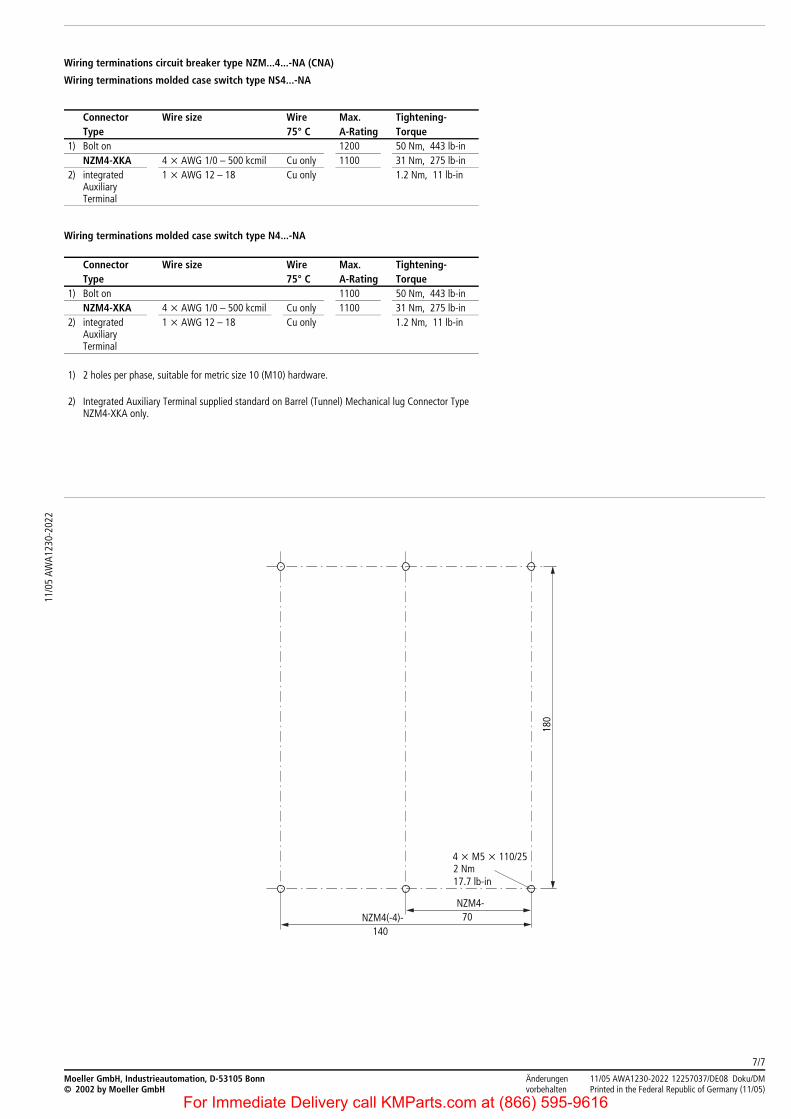
Phase barriers and terminal covers used with NZM4 Molded Case Circuit Breakers and Switches to maintain electrical clearances. Consult respective Connector kit instruction sheets.
2XKP
XKSA
Z 2
f 18
2 Nm, 17.7 lb-in
UL/CSA models:Min. 25.4 mm (1’’)between live conductors of opposite polarity.
5
For Immediate Delivery call KMParts.com at (866) 595-9616
3/7
11/0
5 AW
A123
0-20
22Icc f 50 kA.Icc = Available fault in kiloamps. (RMS sym.)
Leiter mit einem nichtleitenden Material verbinden, das Kurzschlusskräfte von Icc f 50 kA aufnehmen kann.
At higher fault levels (Icc f 50 kA) appropriate bracing of the incoming and outgoing supply conductors is necessary.Location of bracing is not to exceed 200 mm (8’’) from the circuit breaker housing as shown. Bracing material must be non-conductive.
Raccorder les conducteurs avec un matériau non conducteur pouvant supporter des courts-circuits de Icc f 50 kA.
Ancorare i cavi con materiale non conduttivo che possa sopportare sollecitazioni di Icc f 50 kA.
Conectar el cable con material no conductor, el cual puede resistir fuerzas de cortocircuito de Icc f 50 kA.
Провод соединить с непроводящим материалом, могущим воспринимать усилия при короткомзамыкании Icc f 50 kA.
Current setting Long Time Pick-Up Short Time Pick-Up Short Time Pick-Up Inst. Pick-Up I2t
Ir (x c A) Delay at 6 x Ir (sec) (x Ir) Delay (milli-sec.) (x In)
NZM4-VE...-NA X X X X X X
NZM4-VEF...-NA Fixed current Rating X X X X X
NZM4-AE...-NA X – – – X –NZM4-AEF...-NA Fixed current Rating – – – X –
For Immediate Delivery call KMParts.com at (866) 595-9616
4/7
11/0
5 AW
A123
0-20
22
M22-K10M22-K01M22-CK10M22-CK01Auxiliary Switches
-NA, -CNA (UL/CSA)
IEC
HIA HIA HIN HIN HIN
a oder – or – ou – oppure – ó – или –
Notes on mounting and wiring Auxiliary Switches for UL/CSA labeled models:– M22-K (10)(01) have screw terminals. M22-CK (10)(01) have clamp terminals.– Switch modules are snapped into place at the locations shown in the diagrams that follow.– Switches will function as either „standard“ or „trip/alarm“ contacts depending on their mounting location.– Location „HIN“ refers to standard operation. Location „HIA“ refers to „trip/alarm“ operation.– Follow the numbering and wiring scheme provided above depending on the contact location
and function. (N.O. or N.C.)Permissible contact configuration: 2 x HIA and/or 3 x HIN.
Note:After mounting of the M22... switch is complete, check off the appropriate box on the auxiliary switch labelprovided on the side of the breaker or switch.


![LATEXKurs Literaturverzeichnisse · 2017. 12. 10. · nur ein Test (Doe 50 v. Chr., S. 4) nur ein Test ([Doe, S. 4]) Hinweis. Wenn die Punkt Option verwendet wird, muss die Quellen](https://static.unterlagen.site/doc/80x56/610ae5e8ab0e4e1c7d63e009/latexkurs-literaturverzeichnisse-2017-12-10-nur-ein-test-doe-50-v-chr-s.jpg)


