Ballasttraumlger Abdeckplatte am Vorderund Seitenverkleidungen
Falls notwendig Batteriekasten loumlsen
Falls notwendig Tankhalterung loumlsenund Tank etwas nach auszligen zieheneth Traumlgerrahmen unterbauen
Auflageflaumlchen am Vorderachsbock und an der Kupplungsglocke entlacken
bull
bull
bull
bull
achsbockdemontieren
Disassemble ballast support sheet cover at the support of front axle and lateral coverings
If necessary loosen accumulator box
If necessary loosen tank fixing device and pull tank a little outsideeth support frame
Clean surfaces of support of front axle andof clutch housing from colour
MONTAGEVORBEREITUNGENPREPARATION FOR MOUNTING
INDICATION bull
bull
bull
bull
If mounting front linkage and front PTO start with mounting of front PTO
When fixing mounting parts first apply all bolts then tighten them with atorque wrench
The tightening torques indicated apply to dry threads and support surfaces(if not indicated otherwise)
To make mounting easier please use the spare parts lists
HINWEISE bull Bei der Montage von Frontkraftheber und Frontzapfwelle mit der Montage derFrontzapfwelle beginnen
bull Beim Befestigen von Montageteilen zuerst alle Schrauben ansetzen dann erstfestschrauben und mit Drehmomentschluumlssel anziehen
bull
bull
Die angegebenen Anzugsdrehmomente fuumlr Verschraubungen gelten fuumlr trockeneGewinde und Auflageflaumlchen (falls nicht anders angegeben)
Als Montagehilfe nehmen Sie bitte die Ersatzteillisten zur Hand
4
Axion 810-850Frontkraftheber Front linkage
1082 - 60 - 1siehe Ersatzteillistesee spare parts list
42
1
25
2726
25
2422
1617
2423
18
20-
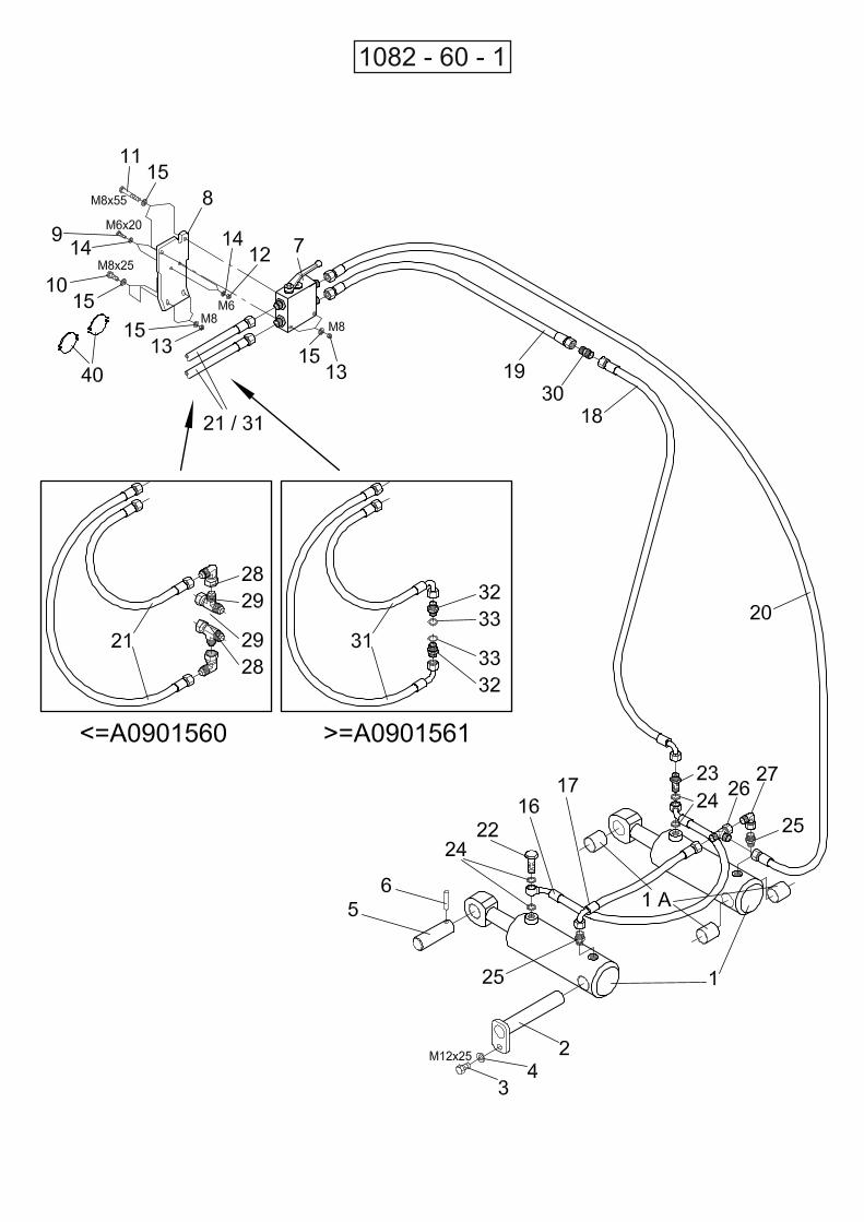
zylinder (1) befestigenbull Hydraulikschlaumluche (18 20) an Hydraulik
Fasten flexible tubes (18 20) at hydraulic cylinders (1)
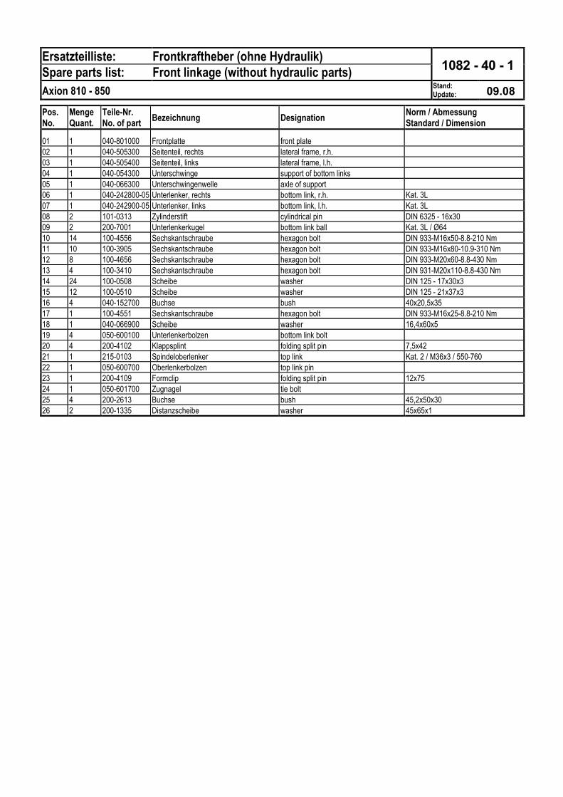
1082 - 40 - 1siehe Ersatzteillistesee spare parts list
41
814
11(M16x80310 Nm)
1014
315
12(M20x60430 Nm)
14
10(M16x50210 Nm)
215
12(M20x60430 Nm)
1615
13(M20x110430 Nm)
113 15 16 Batteriekasten
accumulator box
eth
eth
bull Frontplatte und Seitenteile befestigenzuerst Frontplatte dann Seitenteile ansetzen
Fasten front plate and lateral framesfirst place front platethen lateral frames
MONTAGE DES FRONTKRAFTHEBERSMOUNTING OF FRONT LINKAGE
5
Axion 810-850Frontkraftheber Front linkage
1082-40-1 1082-60-1siehe Ersatzteillistesee spare parts list
52
18 20
193018
unter der Kabine nach hinten verlegen
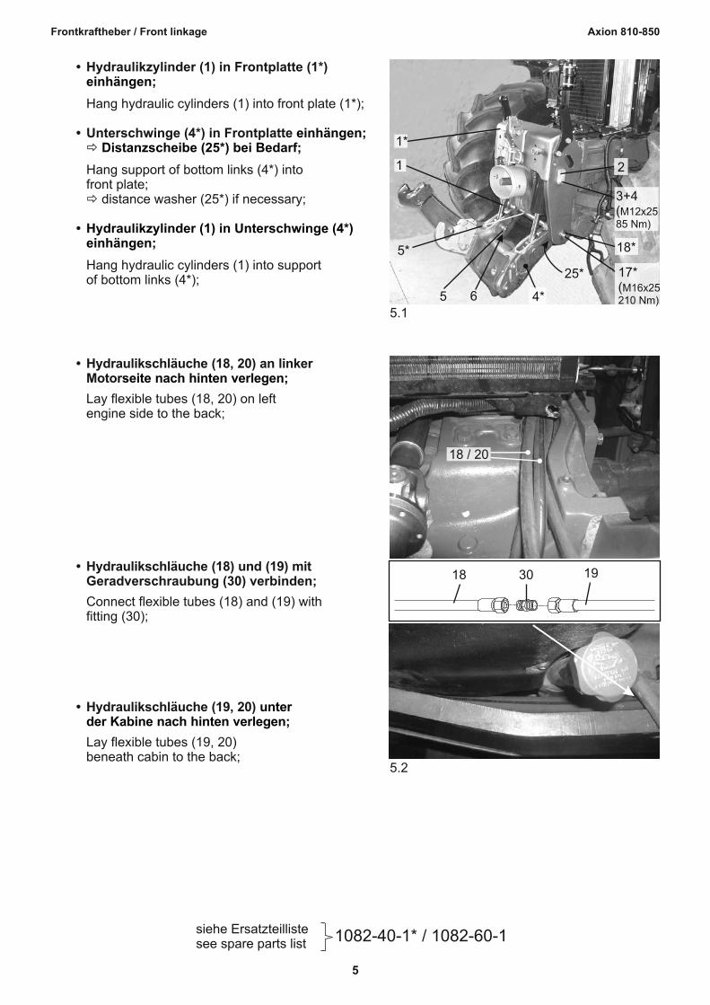
bull Hydraulikschlaumluche (19 20)
Lay flexible tubes (19 20) beneath cabin to the back
bull Hydraulikschlaumluche (18) und (19) mit Geradverschraubung (30) verbinden
Connect flexible tubes (18) and (19) withfitting (30)
seite nach hinten verlegenbull Hydraulikschlaumluche (18 20) an linker
Motor
Lay flexible tubes (18 20) on left engine side to the back
514
1
1
2
3+4(M12x2585 Nm)
18
17(M16x25210 Nm)
25
65
5
einhaumlngen
einhaumlngeneth Distanzscheibe (25) bei Bedarf
eth
Hydraulikzylinder (1) in Unterschwinge (4)einhaumlngen
bull Hydraulikzylinder (1) in Frontplatte (1)
Hang hydraulic cylinders (1) into front plate (1)
bull Unterschwinge (4) in Frontplatte
Hang support of bottom links (4) intofront plate
distance washer (25) if necessary
bull
Hang hydraulic cylinders (1) into supportof bottom links (4)
6
Axion 810-850Frontkraftheber Front linkage
1082 - 60 - 1siehe Ersatzteillistesee spare parts list
63
31
Senkenlowering
Hebenlifting
32 33
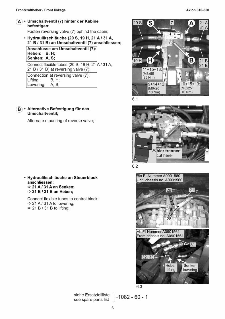
Ab FI-Nummer A0901561From chassis no A0901561
28
29 21
Bis FI-Nummer A0901560Until chassis no A0901560
an Steuerblockanschliesseneth 21 A 31 A an Senkeneth 21 B 31 B an Heben
etheth
bull Hydraulikschlaumluche
Connect flexible tubes to control block 21 A 31 A to lowering 21 B 31 B to lifting
62
hier trennencut here
bull Alternative Befestigung fuumlr das
Umschaltventil
Alternate mounting of reverse valve
B
61
10+15+13(M8x25 10 Nm)
9+14+12(M6x20 10 Nm)
11+15+13(M8x55 25 Nm)
21 B31 B
19 H
21 A31 A
720 S
BH
ASFasten r
bull Umschaltventil (7) hinter der Kabinebefestigen
eversing valve (7) behind the cabin
bull Hydraulikschlaumluche (20 S 19 H 21 A 31 A 21 B 31 B) an Umschaltventil (7) anschliessen
Anschluumlsse am Umschaltventil (7)Heben B HSenken A S
Connect flexible tubes (20 S 19 H 21 A 31 A 21 B 31 B) at reversing valve (7)
Connection at reversing valve (7)Lifting B HLowering A S
A
7
Axion 810-850Frontkraftheber Front linkage
1082 - 40 - 1siehe Ersatzteillistesee spare parts list
72
19
206
7
4
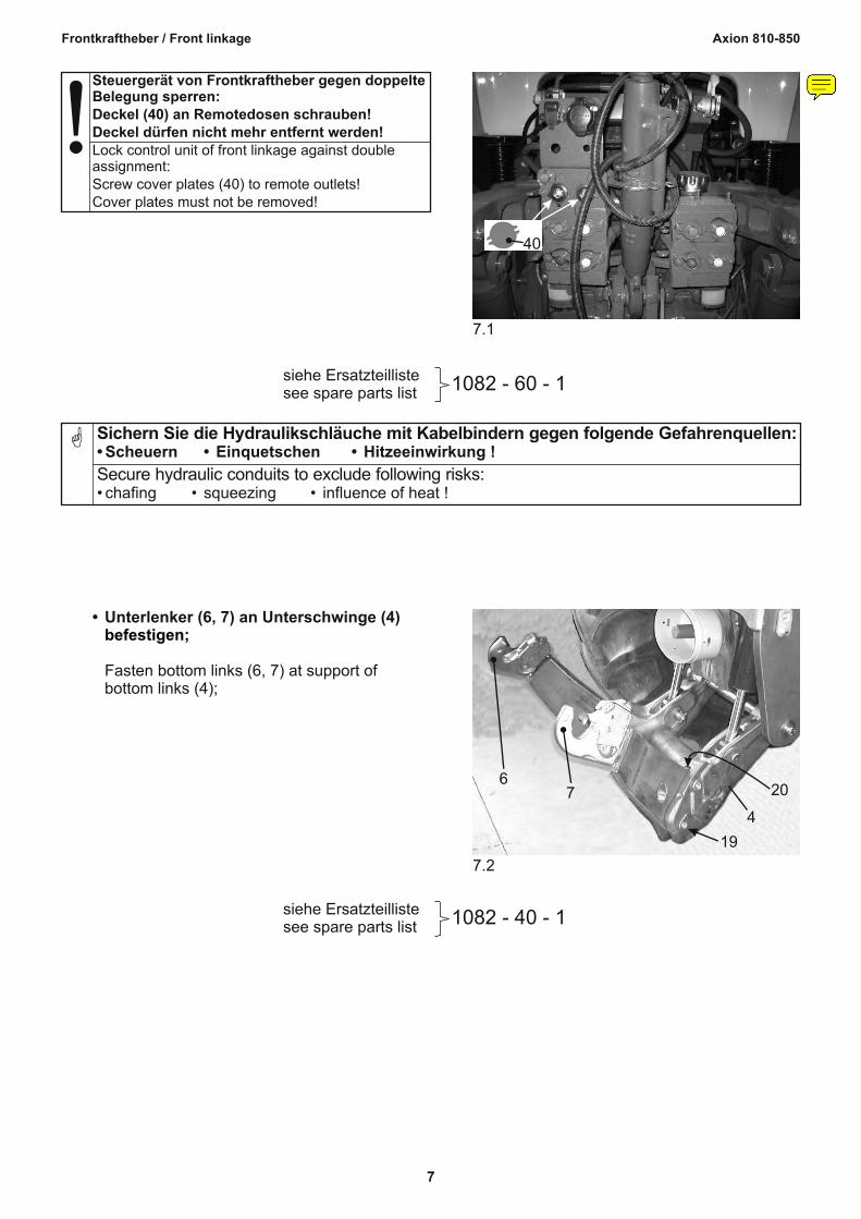
befestigenbull Unterlenker (6 7) an Unterschwinge (4)
Fasten bottom links (6 7) at support ofbottom links (4)
Secure hydraulic conduits to exclude following risksbull chafing bull squeezing bull influence of heat
Sichern Sie die Hydraulikschlaumluche mit Kabelbindern gegen folgende Gefahrenquellenbull Scheuern bull Einquetschen bull Hitzeeinwirkung
G
1082 - 60 - 1siehe Ersatzteillistesee spare parts list
71
40
Lock control unit of front linkage against double assignmentScrew cover plates (40) to remote outletsCover plates must not be removed
Steuergeraumlt von Frontkraftheber gegen doppelteBelegung sperrenDeckel (40) an Remotedosen schraubenDeckel duumlrfen nicht mehr entfernt werden
darabos
Notiz
Aumlnderung zum Stand 090813Hinweistext und Bild 71 neu13-gt Deckel (40) hinzugefuumlgt
8
Axion 810-850Frontkraftheber Front linkage
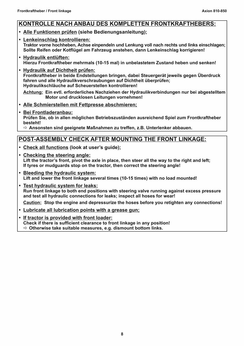
POST-ASSEMBLY CHECK AFTER MOUNTING THE FRONT LINKAGE
ŸCheck all functions (look at userrsquos guide)
ŸChecking the steering angleLift the tractorrsquos front pivot the axle in place then steer all the way to the right and leftIf tyres or mudguards stop on the tractor then correct the steering angle
ŸBleeding the hydraulic systemLift and lower the front linkage several times (10-15 times) with no load mounted
ŸTest hydraulic system for leaksRun front linkage to both end positions with steering valve running against excess pressure and test all hydraulic connections for leaks inspect all hoses for wear
Caution Stop the engine and depressurize the hoses before you retighten any connections
ŸLubricate all lubrication points with a grease gun
ŸIf tractor is provided with front loaderCheck if there is sufficient clearance to front linkage in any positioneth Otherwise take suitable measures eg dismount bottom links
KONTROLLE NACH ANBAU DES KOMPLETTEN FRONTKRAFTHEBERS
ŸLenkeinschlag kontrollierenTraktor vorne hochheben Achse einpendeln und Lenkung voll nach rechts und links einschlagenSollte Reifen oder Kotfluumlgel am Fahrzeug anstehen dann Lenkeinschlag korrigieren
ŸHydraulik entluumlftenHierzu Frontkraftheber mehrmals (10-15 mal) in unbelastetem Zustand heben und senken
ŸHydraulik auf Dichtheit pruumlfenFrontkraftheber in beide Endstellungen bringen dabei Steuergeraumlt jeweils gegen Uumlberdruckfahren und alle Hydraulikverschraubungen auf Dichtheit uumlberpruumlfenHydraulikschlaumluche auf Scheuerstellen kontrollieren
Achtung Ein evtl erforderliches Nachziehen der Hydraulikverbindungen nur bei abgestelltemMotor und drucklosen Leitungen vornehmen
ŸAlle Schmierstellen mit Fettpresse abschmieren
ŸBei FrontladeranbauPruumlfen Sie ob in allen moumlglichen Betriebszustaumlnden ausreichend Spiel zum Frontkraftheberbestehteth Ansonsten sind geeignete Maszlignahmen zu treffen zB Unterlenker abbauen
Ballasttraumlger Abdeckplatte am Vorderund Seitenverkleidungen
Falls notwendig Batteriekasten loumlsen
Falls notwendig Tankhalterung loumlsenund Tank etwas nach auszligen zieheneth Traumlgerrahmen unterbauen
Auflageflaumlchen am Vorderachsbock und an der Kupplungsglocke entlacken
bull
bull
bull
bull
achsbockdemontieren
Disassemble ballast support sheet cover at the support of front axle and lateral coverings
If necessary loosen accumulator box
If necessary loosen tank fixing device and pull tank a little outsideeth support frame
Clean surfaces of support of front axle andof clutch housing from colour
MONTAGEVORBEREITUNGENPREPARATION FOR MOUNTING
INDICATION bull
bull
bull
bull
If mounting front linkage and front PTO start with mounting of front PTO
When fixing mounting parts first apply all bolts then tighten them with atorque wrench
The tightening torques indicated apply to dry threads and support surfaces(if not indicated otherwise)
To make mounting easier please use the spare parts lists
HINWEISE bull Bei der Montage von Frontkraftheber und Frontzapfwelle mit der Montage derFrontzapfwelle beginnen
bull Beim Befestigen von Montageteilen zuerst alle Schrauben ansetzen dann erstfestschrauben und mit Drehmomentschluumlssel anziehen
bull
bull
Die angegebenen Anzugsdrehmomente fuumlr Verschraubungen gelten fuumlr trockeneGewinde und Auflageflaumlchen (falls nicht anders angegeben)
Als Montagehilfe nehmen Sie bitte die Ersatzteillisten zur Hand
4
Axion 810-850Frontkraftheber Front linkage
1082 - 60 - 1siehe Ersatzteillistesee spare parts list
42
1
25
2726
25
2422
1617
2423
18
20-
zylinder (1) befestigenbull Hydraulikschlaumluche (18 20) an Hydraulik
Fasten flexible tubes (18 20) at hydraulic cylinders (1)
1082 - 40 - 1siehe Ersatzteillistesee spare parts list
41
814
11(M16x80310 Nm)
1014
315
12(M20x60430 Nm)
14
10(M16x50210 Nm)
215
12(M20x60430 Nm)
1615
13(M20x110430 Nm)
113 15 16 Batteriekasten
accumulator box
eth
eth
bull Frontplatte und Seitenteile befestigenzuerst Frontplatte dann Seitenteile ansetzen
Fasten front plate and lateral framesfirst place front platethen lateral frames
MONTAGE DES FRONTKRAFTHEBERSMOUNTING OF FRONT LINKAGE
5
Axion 810-850Frontkraftheber Front linkage
1082-40-1 1082-60-1siehe Ersatzteillistesee spare parts list
52
18 20
193018
unter der Kabine nach hinten verlegen
bull Hydraulikschlaumluche (19 20)
Lay flexible tubes (19 20) beneath cabin to the back
bull Hydraulikschlaumluche (18) und (19) mit Geradverschraubung (30) verbinden
Connect flexible tubes (18) and (19) withfitting (30)
seite nach hinten verlegenbull Hydraulikschlaumluche (18 20) an linker
Motor
Lay flexible tubes (18 20) on left engine side to the back
514
1
1
2
3+4(M12x2585 Nm)
18
17(M16x25210 Nm)
25
65
5
einhaumlngen
einhaumlngeneth Distanzscheibe (25) bei Bedarf
eth
Hydraulikzylinder (1) in Unterschwinge (4)einhaumlngen
bull Hydraulikzylinder (1) in Frontplatte (1)
Hang hydraulic cylinders (1) into front plate (1)
bull Unterschwinge (4) in Frontplatte
Hang support of bottom links (4) intofront plate
distance washer (25) if necessary
bull
Hang hydraulic cylinders (1) into supportof bottom links (4)
6
Axion 810-850Frontkraftheber Front linkage
1082 - 60 - 1siehe Ersatzteillistesee spare parts list
63
31
Senkenlowering
Hebenlifting
32 33
Ab FI-Nummer A0901561From chassis no A0901561
28
29 21
Bis FI-Nummer A0901560Until chassis no A0901560
an Steuerblockanschliesseneth 21 A 31 A an Senkeneth 21 B 31 B an Heben
etheth
bull Hydraulikschlaumluche
Connect flexible tubes to control block 21 A 31 A to lowering 21 B 31 B to lifting
62
hier trennencut here
bull Alternative Befestigung fuumlr das
Umschaltventil
Alternate mounting of reverse valve
B
61
10+15+13(M8x25 10 Nm)
9+14+12(M6x20 10 Nm)
11+15+13(M8x55 25 Nm)
21 B31 B
19 H
21 A31 A
720 S
BH
ASFasten r
bull Umschaltventil (7) hinter der Kabinebefestigen
eversing valve (7) behind the cabin
bull Hydraulikschlaumluche (20 S 19 H 21 A 31 A 21 B 31 B) an Umschaltventil (7) anschliessen
Anschluumlsse am Umschaltventil (7)Heben B HSenken A S
Connect flexible tubes (20 S 19 H 21 A 31 A 21 B 31 B) at reversing valve (7)
Connection at reversing valve (7)Lifting B HLowering A S
A
7
Axion 810-850Frontkraftheber Front linkage
1082 - 40 - 1siehe Ersatzteillistesee spare parts list
72
19
206
7
4
befestigenbull Unterlenker (6 7) an Unterschwinge (4)
Fasten bottom links (6 7) at support ofbottom links (4)
Secure hydraulic conduits to exclude following risksbull chafing bull squeezing bull influence of heat
Sichern Sie die Hydraulikschlaumluche mit Kabelbindern gegen folgende Gefahrenquellenbull Scheuern bull Einquetschen bull Hitzeeinwirkung
G
1082 - 60 - 1siehe Ersatzteillistesee spare parts list
71
40
Lock control unit of front linkage against double assignmentScrew cover plates (40) to remote outletsCover plates must not be removed
Steuergeraumlt von Frontkraftheber gegen doppelteBelegung sperrenDeckel (40) an Remotedosen schraubenDeckel duumlrfen nicht mehr entfernt werden
darabos
Notiz
Aumlnderung zum Stand 090813Hinweistext und Bild 71 neu13-gt Deckel (40) hinzugefuumlgt
8
Axion 810-850Frontkraftheber Front linkage
POST-ASSEMBLY CHECK AFTER MOUNTING THE FRONT LINKAGE
ŸCheck all functions (look at userrsquos guide)
ŸChecking the steering angleLift the tractorrsquos front pivot the axle in place then steer all the way to the right and leftIf tyres or mudguards stop on the tractor then correct the steering angle
ŸBleeding the hydraulic systemLift and lower the front linkage several times (10-15 times) with no load mounted
ŸTest hydraulic system for leaksRun front linkage to both end positions with steering valve running against excess pressure and test all hydraulic connections for leaks inspect all hoses for wear
Caution Stop the engine and depressurize the hoses before you retighten any connections
ŸLubricate all lubrication points with a grease gun
ŸIf tractor is provided with front loaderCheck if there is sufficient clearance to front linkage in any positioneth Otherwise take suitable measures eg dismount bottom links
KONTROLLE NACH ANBAU DES KOMPLETTEN FRONTKRAFTHEBERS
ŸLenkeinschlag kontrollierenTraktor vorne hochheben Achse einpendeln und Lenkung voll nach rechts und links einschlagenSollte Reifen oder Kotfluumlgel am Fahrzeug anstehen dann Lenkeinschlag korrigieren
ŸHydraulik entluumlftenHierzu Frontkraftheber mehrmals (10-15 mal) in unbelastetem Zustand heben und senken
ŸHydraulik auf Dichtheit pruumlfenFrontkraftheber in beide Endstellungen bringen dabei Steuergeraumlt jeweils gegen Uumlberdruckfahren und alle Hydraulikverschraubungen auf Dichtheit uumlberpruumlfenHydraulikschlaumluche auf Scheuerstellen kontrollieren
Achtung Ein evtl erforderliches Nachziehen der Hydraulikverbindungen nur bei abgestelltemMotor und drucklosen Leitungen vornehmen
ŸAlle Schmierstellen mit Fettpresse abschmieren
ŸBei FrontladeranbauPruumlfen Sie ob in allen moumlglichen Betriebszustaumlnden ausreichend Spiel zum Frontkraftheberbestehteth Ansonsten sind geeignete Maszlignahmen zu treffen zB Unterlenker abbauen
1082 - 60 - 1siehe Ersatzteillistesee spare parts list
42
1
25
2726
25
2422
1617
2423
18
20-
zylinder (1) befestigenbull Hydraulikschlaumluche (18 20) an Hydraulik
Fasten flexible tubes (18 20) at hydraulic cylinders (1)
1082 - 40 - 1siehe Ersatzteillistesee spare parts list
41
814
11(M16x80310 Nm)
1014
315
12(M20x60430 Nm)
14
10(M16x50210 Nm)
215
12(M20x60430 Nm)
1615
13(M20x110430 Nm)
113 15 16 Batteriekasten
accumulator box
eth
eth
bull Frontplatte und Seitenteile befestigenzuerst Frontplatte dann Seitenteile ansetzen
Fasten front plate and lateral framesfirst place front platethen lateral frames
MONTAGE DES FRONTKRAFTHEBERSMOUNTING OF FRONT LINKAGE
5
Axion 810-850Frontkraftheber Front linkage
1082-40-1 1082-60-1siehe Ersatzteillistesee spare parts list
52
18 20
193018
unter der Kabine nach hinten verlegen
bull Hydraulikschlaumluche (19 20)
Lay flexible tubes (19 20) beneath cabin to the back
bull Hydraulikschlaumluche (18) und (19) mit Geradverschraubung (30) verbinden
Connect flexible tubes (18) and (19) withfitting (30)
seite nach hinten verlegenbull Hydraulikschlaumluche (18 20) an linker
Motor
Lay flexible tubes (18 20) on left engine side to the back
514
1
1
2
3+4(M12x2585 Nm)
18
17(M16x25210 Nm)
25
65
5
einhaumlngen
einhaumlngeneth Distanzscheibe (25) bei Bedarf
eth
Hydraulikzylinder (1) in Unterschwinge (4)einhaumlngen
bull Hydraulikzylinder (1) in Frontplatte (1)
Hang hydraulic cylinders (1) into front plate (1)
bull Unterschwinge (4) in Frontplatte
Hang support of bottom links (4) intofront plate
distance washer (25) if necessary
bull
Hang hydraulic cylinders (1) into supportof bottom links (4)
6
Axion 810-850Frontkraftheber Front linkage
1082 - 60 - 1siehe Ersatzteillistesee spare parts list
63
31
Senkenlowering
Hebenlifting
32 33
Ab FI-Nummer A0901561From chassis no A0901561
28
29 21
Bis FI-Nummer A0901560Until chassis no A0901560
an Steuerblockanschliesseneth 21 A 31 A an Senkeneth 21 B 31 B an Heben
etheth
bull Hydraulikschlaumluche
Connect flexible tubes to control block 21 A 31 A to lowering 21 B 31 B to lifting
62
hier trennencut here
bull Alternative Befestigung fuumlr das
Umschaltventil
Alternate mounting of reverse valve
B
61
10+15+13(M8x25 10 Nm)
9+14+12(M6x20 10 Nm)
11+15+13(M8x55 25 Nm)
21 B31 B
19 H
21 A31 A
720 S
BH
ASFasten r
bull Umschaltventil (7) hinter der Kabinebefestigen
eversing valve (7) behind the cabin
bull Hydraulikschlaumluche (20 S 19 H 21 A 31 A 21 B 31 B) an Umschaltventil (7) anschliessen
Anschluumlsse am Umschaltventil (7)Heben B HSenken A S
Connect flexible tubes (20 S 19 H 21 A 31 A 21 B 31 B) at reversing valve (7)
Connection at reversing valve (7)Lifting B HLowering A S
A
7
Axion 810-850Frontkraftheber Front linkage
1082 - 40 - 1siehe Ersatzteillistesee spare parts list
72
19
206
7
4
befestigenbull Unterlenker (6 7) an Unterschwinge (4)
Fasten bottom links (6 7) at support ofbottom links (4)
Secure hydraulic conduits to exclude following risksbull chafing bull squeezing bull influence of heat
Sichern Sie die Hydraulikschlaumluche mit Kabelbindern gegen folgende Gefahrenquellenbull Scheuern bull Einquetschen bull Hitzeeinwirkung
G
1082 - 60 - 1siehe Ersatzteillistesee spare parts list
71
40
Lock control unit of front linkage against double assignmentScrew cover plates (40) to remote outletsCover plates must not be removed
Steuergeraumlt von Frontkraftheber gegen doppelteBelegung sperrenDeckel (40) an Remotedosen schraubenDeckel duumlrfen nicht mehr entfernt werden
darabos
Notiz
Aumlnderung zum Stand 090813Hinweistext und Bild 71 neu13-gt Deckel (40) hinzugefuumlgt
8
Axion 810-850Frontkraftheber Front linkage
POST-ASSEMBLY CHECK AFTER MOUNTING THE FRONT LINKAGE
ŸCheck all functions (look at userrsquos guide)
ŸChecking the steering angleLift the tractorrsquos front pivot the axle in place then steer all the way to the right and leftIf tyres or mudguards stop on the tractor then correct the steering angle
ŸBleeding the hydraulic systemLift and lower the front linkage several times (10-15 times) with no load mounted
ŸTest hydraulic system for leaksRun front linkage to both end positions with steering valve running against excess pressure and test all hydraulic connections for leaks inspect all hoses for wear
Caution Stop the engine and depressurize the hoses before you retighten any connections
ŸLubricate all lubrication points with a grease gun
ŸIf tractor is provided with front loaderCheck if there is sufficient clearance to front linkage in any positioneth Otherwise take suitable measures eg dismount bottom links
KONTROLLE NACH ANBAU DES KOMPLETTEN FRONTKRAFTHEBERS
ŸLenkeinschlag kontrollierenTraktor vorne hochheben Achse einpendeln und Lenkung voll nach rechts und links einschlagenSollte Reifen oder Kotfluumlgel am Fahrzeug anstehen dann Lenkeinschlag korrigieren
ŸHydraulik entluumlftenHierzu Frontkraftheber mehrmals (10-15 mal) in unbelastetem Zustand heben und senken
ŸHydraulik auf Dichtheit pruumlfenFrontkraftheber in beide Endstellungen bringen dabei Steuergeraumlt jeweils gegen Uumlberdruckfahren und alle Hydraulikverschraubungen auf Dichtheit uumlberpruumlfenHydraulikschlaumluche auf Scheuerstellen kontrollieren
Achtung Ein evtl erforderliches Nachziehen der Hydraulikverbindungen nur bei abgestelltemMotor und drucklosen Leitungen vornehmen
ŸAlle Schmierstellen mit Fettpresse abschmieren
ŸBei FrontladeranbauPruumlfen Sie ob in allen moumlglichen Betriebszustaumlnden ausreichend Spiel zum Frontkraftheberbestehteth Ansonsten sind geeignete Maszlignahmen zu treffen zB Unterlenker abbauen
1082 - 60 - 1siehe Ersatzteillistesee spare parts list
63
31
Senkenlowering
Hebenlifting
32 33
Ab FI-Nummer A0901561From chassis no A0901561
28
29 21
Bis FI-Nummer A0901560Until chassis no A0901560
an Steuerblockanschliesseneth 21 A 31 A an Senkeneth 21 B 31 B an Heben
etheth
bull Hydraulikschlaumluche
Connect flexible tubes to control block 21 A 31 A to lowering 21 B 31 B to lifting
62
hier trennencut here
bull Alternative Befestigung fuumlr das
Umschaltventil
Alternate mounting of reverse valve
B
61
10+15+13(M8x25 10 Nm)
9+14+12(M6x20 10 Nm)
11+15+13(M8x55 25 Nm)
21 B31 B
19 H
21 A31 A
720 S
BH
ASFasten r
bull Umschaltventil (7) hinter der Kabinebefestigen
eversing valve (7) behind the cabin
bull Hydraulikschlaumluche (20 S 19 H 21 A 31 A 21 B 31 B) an Umschaltventil (7) anschliessen
Anschluumlsse am Umschaltventil (7)Heben B HSenken A S
Connect flexible tubes (20 S 19 H 21 A 31 A 21 B 31 B) at reversing valve (7)
Connection at reversing valve (7)Lifting B HLowering A S
A
7
Axion 810-850Frontkraftheber Front linkage
1082 - 40 - 1siehe Ersatzteillistesee spare parts list
72
19
206
7
4
befestigenbull Unterlenker (6 7) an Unterschwinge (4)
Fasten bottom links (6 7) at support ofbottom links (4)
Secure hydraulic conduits to exclude following risksbull chafing bull squeezing bull influence of heat
Sichern Sie die Hydraulikschlaumluche mit Kabelbindern gegen folgende Gefahrenquellenbull Scheuern bull Einquetschen bull Hitzeeinwirkung
G
1082 - 60 - 1siehe Ersatzteillistesee spare parts list
71
40
Lock control unit of front linkage against double assignmentScrew cover plates (40) to remote outletsCover plates must not be removed
Steuergeraumlt von Frontkraftheber gegen doppelteBelegung sperrenDeckel (40) an Remotedosen schraubenDeckel duumlrfen nicht mehr entfernt werden
darabos
Notiz
Aumlnderung zum Stand 090813Hinweistext und Bild 71 neu13-gt Deckel (40) hinzugefuumlgt
8
Axion 810-850Frontkraftheber Front linkage
POST-ASSEMBLY CHECK AFTER MOUNTING THE FRONT LINKAGE
ŸCheck all functions (look at userrsquos guide)
ŸChecking the steering angleLift the tractorrsquos front pivot the axle in place then steer all the way to the right and leftIf tyres or mudguards stop on the tractor then correct the steering angle
ŸBleeding the hydraulic systemLift and lower the front linkage several times (10-15 times) with no load mounted
ŸTest hydraulic system for leaksRun front linkage to both end positions with steering valve running against excess pressure and test all hydraulic connections for leaks inspect all hoses for wear
Caution Stop the engine and depressurize the hoses before you retighten any connections
ŸLubricate all lubrication points with a grease gun
ŸIf tractor is provided with front loaderCheck if there is sufficient clearance to front linkage in any positioneth Otherwise take suitable measures eg dismount bottom links
KONTROLLE NACH ANBAU DES KOMPLETTEN FRONTKRAFTHEBERS
ŸLenkeinschlag kontrollierenTraktor vorne hochheben Achse einpendeln und Lenkung voll nach rechts und links einschlagenSollte Reifen oder Kotfluumlgel am Fahrzeug anstehen dann Lenkeinschlag korrigieren
ŸHydraulik entluumlftenHierzu Frontkraftheber mehrmals (10-15 mal) in unbelastetem Zustand heben und senken
ŸHydraulik auf Dichtheit pruumlfenFrontkraftheber in beide Endstellungen bringen dabei Steuergeraumlt jeweils gegen Uumlberdruckfahren und alle Hydraulikverschraubungen auf Dichtheit uumlberpruumlfenHydraulikschlaumluche auf Scheuerstellen kontrollieren
Achtung Ein evtl erforderliches Nachziehen der Hydraulikverbindungen nur bei abgestelltemMotor und drucklosen Leitungen vornehmen
ŸAlle Schmierstellen mit Fettpresse abschmieren
ŸBei FrontladeranbauPruumlfen Sie ob in allen moumlglichen Betriebszustaumlnden ausreichend Spiel zum Frontkraftheberbestehteth Ansonsten sind geeignete Maszlignahmen zu treffen zB Unterlenker abbauen