12
5

5
Kollo2002_e.book Seite 61 Mittwoch, 6. März 2002 5:52 17

Kollo2002_e.book Seite 62 Mittwoch, 6. März 2002 5:52 17
63LuK SYMPOSIUM 2002
Latest Results in theCVT Development
Norbert IndlekoferUwe WagnerAlexander FidlinAndré Teubert
5
Kollo2002_e.book Seite 63 Mittwoch, 6. März 2002 5:52 17
5 Latest Results in the CVT Development
64 LuK SYMPOSIUM 2002
IntroductionThe main requirements of the drive trains forthe future are defined: Further fuel saving withsimultaneous increase in driving dynamics,while maintaining at least the same level ofcomfort. These aims must be achieved with in-creasing engine torques but also without com-promise to costing strategy.
The multitronic� transmission from Audi, fea-turing major components produced by LuK,presents a very good solution for the abovementioned requirements. Also, during the de-velopment of this project, there was a require-ment for increases in torque capacity. Theoriginal transmission arrangement envisaged250 Nm, meanwhile 310 Nm units are in pro-duction, with further torque increases about tobe introduced.
This article will address three main points ofthe CVT development:
� Increasing torque capacity
� Improving efficiency
� Increasing acoustic comfort
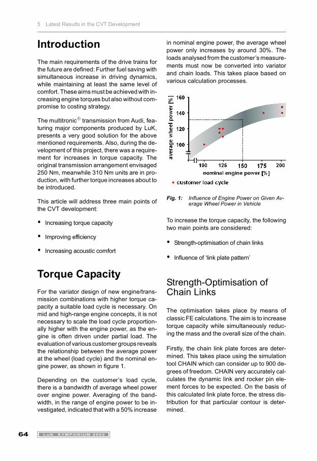
Torque CapacityFor the variator design of new engine/trans-mission combinations with higher torque ca-pacity a suitable load cycle is necessary. Onmid and high-range engine concepts, it is notnecessary to scale the load cycle proportion-ally higher with the engine power, as the en-gine is often driven under partial load. Theevaluation of various customer groups revealsthe relationship between the average powerat the wheel (load cycle) and the nominal en-gine power, as shown in figure 1.
Depending on the customer’s load cycle,there is a bandwidth of average wheel powerover engine power. Averaging of the band-width, in the range of engine power to be in-vestigated, indicated that with a 50% increase
in nominal engine power, the average wheelpower only increases by around 30%. Theloads analysed from the customer’s measure-ments must now be converted into variatorand chain loads. This takes place based onvarious calculation processes.
Fig. 1: Influence of Engine Power on Given Av-erage Wheel Power in Vehicle
To increase the torque capacity, the followingtwo main points are considered:
� Strength-optimisation of chain links
� Influence of ‘link plate pattern’
Strength-Optimisation of Chain Links
The optimisation takes place by means ofclassic FE calculations. The aim is to increasetorque capacity while simultaneously reduc-ing the mass and the overall size of the chain.
Firstly, the chain link plate forces are deter-mined. This takes place using the simulationtool CHAIN which can consider up to 900 de-grees of freedom. CHAIN very accurately cal-culates the dynamic link and rocker pin ele-ment forces to be expected. On the basis ofthis calculated link plate force, the stress dis-tribution for that particular contour is deter-mined.
Kollo2002_e.book Seite 64 Mittwoch, 6. März 2002 5:52 17

5 Latest Results in the CVT Development
65LuK SYMPOSIUM 2002
Fig. 2: Link Stress Distribution
Fig. 3: Contour Formation According to Biological Growth
Fig. 4: Original Geometry and New Contour
In the following optimisation, the calculationprogram uses the principle laws of growth, asthey exist in nature (bionic method).
The basic principle of this method is the re-moval of material in areas of low stress andthe addition of material in areas of high stress.
Figure 4 compares the original and the opti-mised link geometry. The new geometry, re-ferred to in the following as ‘light-variant’, hasa 17% reduced mass and a 15% lower radialdimension. Additionally, the maximum stressreduces by around 5%.
The significantly lower mass and the associ-ated lower centrifugal forces have a very pos-itive effect on the link plate stresses (-5%) athigh speeds.
On today's chain variator arrangements, thechain is no longer the determining factor forthe minimum possible running radius, theshaft strength is. The radial space gain fromthe link optimisation is therefore used to in-crease the shaft diameters. Thus, the neces-sary stress reduction of the shaft is achievedwithout reducing the ratio spread.
The results of the computer-optimised linkplates are meanwhile verified during trials. Forthis, the link plates undergo standard pulsetests. The running times of the optimised chaincontour are around 1.3 times greater than thatof the original contour.
Link Plate Pattern of ChainTrials on test benches and in vehicles unani-mously show that with the current chain de-signs there are still available reserves regard-ing loading of the rocker pin elements. This po-tential can be exploited by varying the link platepattern, i.e. the arrangement of link platesacross the width of the chain. This should fur-ther reduce the loading on the links, wherebythe loading on the rocker pin elements is in-creased. The main aim is to find a link platepattern whereby both chain links and rockerpin elements are proportionally loaded andconsequently also exploited to the maximum.
Kollo2002_e.book Seite 65 Mittwoch, 6. März 2002 5:52 17

5 Latest Results in the CVT Development
66 LuK SYMPOSIUM 2002
Bild 5: Comparison, MATLAB® and CHAIN Calculations at Three Different Load Points
The number of possible link plate patterns canbe significantly limited by setting necessarymarginal conditions. The previously men-tioned CHAIN calculation program is not con-sidered viable for evaluation of the variousconceivable variations because of its process-ing time. Therefore, a simplified calculationprogram based on MATLAB® has been devel-oped for the pre-selection process.
Figure 5 shows that the qualitative consisten-cy of results is good, and therefore this is a per-missible simplification.
Only a few link plate patterns, on which thecomponent loading in total was minimal, arebuilt as prototypes and tested.
The running times of the chains with optimisedlink plate pattern are around 2 times greaterthan those of the original variants (figure 6).
Fig. 6: Chain Run Performance
Kollo2002_e.book Seite 66 Mittwoch, 6. März 2002 5:52 17
5 Latest Results in the CVT Development
67LuK SYMPOSIUM 2002
Torque Capacity, Conclusion
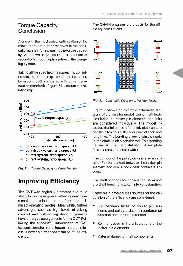
Along with the mechanical optimisation of thechain, there are further reserves in the appli-cation system for increasing the torque capac-ity. As shown in [2], there is a potential ofaround 5% through optimisation of the clamp-ing system.
Taking all the specified measures into consid-eration, the torque capacity can be increasedby around 30% compared with current pro-duction standards. Figure 7 illustrates this re-lationship.
Fig. 7: Torque Capacity of Chain Variator
Improving EfficiencyThe CVT was originally promoted due to itsability to run the engine at either its most con-sumption-optimised or performance-opti-mised operating modes. Meanwhile, furtheradvantages such as high levels of drivingcomfort and outstanding driving dynamicshave emerged as arguments for the CVT. Fol-lowing the successful introduction of CVTtransmissions for higher torque ranges, the fo-cus is now on further optimisation of the effi-ciency.
The CHAIN program is the basis for the effi-ciency calculations.
Fig. 8: Schematic Diagram of Variator Model
Figure 8 shows an example schematic dia-gram of the variator model. Using multi-bodysimulation, all rocker pin elements and linksare considered individually. The model in-cludes the influence of the link plate patternand the pitching, i.e. the sequence of short andlong links. The bending of rocker pin elementsin the chain is also considered. This bendingcauses an unequal distribution of link plateforces across the chain width.
The contour of the pulley disks is also a vari-able. For the contact between the rocker pinelement and disk a non-linear contact is ap-plied.
The shaft bearings are applied non-linear andthe shaft bending is taken into consideration.
Three main physical loss sources for the cal-culation of the efficiency are considered:
� Slip between faces of rocker pin ele-ments and pulley disks in circumferentialdirection and in radial direction
� Rolling losses in the articulations of therocker pin elements
� Material damping in all components
Kollo2002_e.book Seite 67 Mittwoch, 6. März 2002 5:52 17

5 Latest Results in the CVT Development
68 LuK SYMPOSIUM 2002
Fig. 9: Dependency of Efficiency on Ratio (a) and on Engine Torque (b), Calculated with CHAIN Program
Figure 9 shows the dependency of the effi-ciency on the variator ratio or transmission in-put torque, for two different speeds. The indi-cated theoretical values equate well to the firstcorresponding measurements.
Geometrically differing variants have beencalculated for further optimisation.
Figure 10 shows the corresponding calcula-tion results.
The advantage of the current series (A) com-pared to version C with 7° pulley set angle isclearly recognisable.
The difference between version B and the cur-rent series (A) is minimal. The series versionis more efficient in overdrive than version B.This is very advantageous, as a high propor-tion of all driving across the whole load cycletakes place close to the overdrive range.
In version D, the efficiency increases byaround half a percent through increasing theshaft rigidity.
Fig. 10: Influence of Pulley Set Geometry on Efficiency
The negative effect of excessive clamping forceon efficiency can be clearly seen. As shown in[2], optimising the application system would beexpected to improve efficiency by around 2%.This is mainly due to the reduction of losses inthe variator and also due to the reduction in thepower consumption of the pump.
The reserves in torque capacity shown in theprevious chapter can alternatively be used toincrease the gear ratio spread. The maximumspread of CVT transmissions are currentlyaround 6.0. Further consumption reductionsare to be expected, up to an increase in spreadof between 6.5 and 7.0. Ratio spreads beyondthis are no longer sensible, as the efficiencydrops back again due to the necessary adjust-ment dynamics and the consequential systemdesign. A spread increase from 6.0 to 6.5 ina middle class vehicle with around 300 Nm en-gine torque, results in a consumption reduc-tion of around 1%.
variants pulle
y se
t-ge
omet
ry
chai
n
note
basic A
curved 37 mm production multitronic�
B 11° 37 mm -
C 7° 37 mm -
D curved 37 mm ‘light’
shaft: Ø + 2 mm
E curved 37 mm 30% over-clamping
Kollo2002_e.book Seite 68 Mittwoch, 6. März 2002 5:52 17

5 Latest Results in the CVT Development
69LuK SYMPOSIUM 2002
Overall, by improving the application system(2%) and using the increased spread (1%), thetotal consumption can be lowered by a good3%. A well designed CVT has therefore thepotential to also significantly undercut the new6-speed stepped automatic transmission ve-hicles in consumption.
AcousticsA main focus in the CVT development for pro-duction use is the acoustic optimisation of thechain and the transmission structure.
Acoustic Optimisation of the ChainAs shown in [1], a proficient distribution ofshort and long links greatly reduces the mon-otone consistency of the chain. The pitchingis referred to as ‘Random’ in the following text.
Figure 11 compares a single pitch chain to arandom chain. In the artificial head measure-ments shown, at a constant engine speed thevehicle is continuously decelerated. The illus-tration shows the frequency over the decreas-ing vehicle speed. The intensity is shown incolour.
The monotone consistency is clearly recog-nisable on the single pitch chain, while it dis-appears with the random chain. However, thischange from the tone consistency to noise hascaused the level to increase in other areas.
The consecutive impact of rocker pin ele-ments represents the excitation frequency ofthe chain. Alongside this excitation frequency,the spectrum of the chain acoustics also in-cludes the chain revolution frequency and itsmultiples. These so-called modulation noisesare caused by broad-band excitation of thechain. Along with the reduction of the mono-tone consistency, as low a modulation noiseas possible is the aim.
Bild 11: Acoustic Optimisation through Pitching
Kollo2002_e.book Seite 69 Mittwoch, 6. März 2002 5:52 17
5 Latest Results in the CVT Development
70 LuK SYMPOSIUM 2002
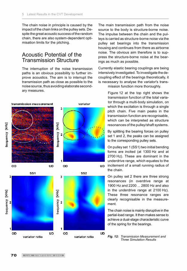
The chain noise in principle is caused by theimpact of the chain links on the pulley sets. De-spite the great acoustic success of the randomchain, there are also system-dependent opti-misation limits for the pitching.
Acoustic Potential of the Transmission StructureThe interruption of the noise transmissionpaths is an obvious possibility to further im-prove acoustics. The aim is to interrupt thetransmission path as close as possible to thenoise source, thus avoiding elaborate second-ary measures.
The main transmission path from the noisesource to the body is structure-borne noise.The impulse between the chain and the pul-leys is carried as structure-borne noise via thepulley set bearings into the transmissionhousing and continues from there as airbornenoise. The obvious aim therefore is to sup-press the structure-borne noise at the bear-ings as much as possible.
Currently elastic bearing couplings are beingintensively investigated. To investigate the de-coupling effect of the bearings theoretically, itis necessary to analyse the variator's trans-
mission function more thoroughly.
Figure 12 at the top right shows thetransmission function of the total varia-tor through a multi-body simulation, onwhich the excitation is through a singlepitch chain. Five main peaks in thetransmission function are recognisable,which can be interpreted as structureresonances of the pulley/shaft systems.
By splitting the bearing forces on pulleyset 1 and 2, the peaks can be assignedto the corresponding pulley sets.
On pulley set 1 (SS1) two initial bendingforms are incited (at 1300 Hz and at2700 Hz). These are dominant in theunderdrive range, which equates to theincitement of a small running radius ofthe chain.
On pulley set 2 there are three strongresonances (in overdrive range at1900 Hz and 2200 ... 2800 Hz and alsoin the underdrive range at 2100 Hz).These three resonance ranges areclearly recognisable in the measure-ment.
The chain noise is mainly disruptive in thepartial-load range. It then makes sense toachieve a dual-stage characteristic curveof the spring for the bearings.
Fig. 12: Transmission Measurement and Three Simulation Results
Kollo2002_e.book Seite 70 Mittwoch, 6. März 2002 5:52 17
5 Latest Results in the CVT Development
71LuK SYMPOSIUM 2002
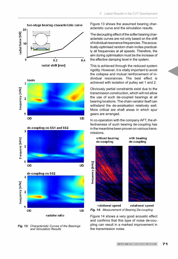
Fig. 13: Characteristic Curves of the Bearings and Simulation Results
Figure 13 shows the assumed bearing char-acteristic curve and the simulation results.
The decoupling effect of the softer bearing char-acteristic curves are not only based on the shiftof individual resonance frequencies. The acous-tically-optimised random chain incites practical-ly all frequencies at all speeds. Therefore, theaim during optimisation must be the increase ofthe effective damping level in the system.
This is achieved through the reduced systemrigidity. However, it is vitally important to avoidthe collapse and mutual reinforcement of in-dividual resonances. The best effect isachieved with isolation of pulley set 1 and 2.
Obviously partial constraints exist due to thetransmission construction, which will not allowthe use of such de-coupled bearings at allbearing locations. The chain variator itself canwithstand the de-axialisation relatively well.More critical are shaft areas in which spurgears are arranged.
In co-operation with the company AFT, the ef-fectiveness of such bearing de-coupling hasin the meantime been proven on various trans-missions.
Fig. 14: Measurement of Bearing De-coupling
Figure 14 shows a very good acoustic effectand confirms that this type of noise de-cou-pling can result in a marked improvement inthe transmission noise.
Kollo2002_e.book Seite 71 Mittwoch, 6. März 2002 5:52 17

5 Latest Results in the CVT Development
72 LuK SYMPOSIUM 2002
SummaryAn essential point of the current developmentof chain variators is the further increase intorque capacity. Currently it is possible totransmit torques of around 400 Nm with a var-iator centre distance of approx. 170-180 mmand a transmission spread of 6.0. Multi-rangestructures, as shown in [3], are a possiblemeans of further increasing torque capacities.
Further progress was made with the optimi-sation of the efficiency. In this way the CVTtransmission can also retain its consumptionadvantage over manual shift transmissionsand the latest 6-speed stepped automatictransmissions.
There are also new approaches to further im-prove the acoustics. Alongside the previousoptimisation of the pitching, acoustic meas-ures on noise transmission paths are also be-ing investigated. The elastic de-coupling be-tween the variator bearings and the housinghas proved particularly promising.
The CVT transmission also shows its marketviability with regard to cost in comparison withother transmission types.
This then provides all the necessary prereq-uisites for the CVT transmission to enjoy asuccessful future on the market.
References[1] Faust, H.; Linnenbrügger, A.: CVT-De-
velopment at LuK, 6th LuK Symposium1998.
[2] Faust, H.; Homm, M.; Bitzer, F.: Opti-mising the Efficiency of a CVT Clamp-ing System – Reducing Consumptionthrough Increased Slip, 7th LuK Sympo-sium 2002.
[3] Lauinger, C.; Englisch, A.; Wagner, U.:500 Nm CVT – LuK Components inPower Split, 7th LuK Symposium 2002.
Kollo2002_e.book Seite 72 Mittwoch, 6. März 2002 5:52 17


