Situation, die bei Missachtung des Hinweises zu einer Gefährdung, Beschädigung von Material oder zu Betriebsstörungen führen kann.
Wichtige Informationen für Anwender und Techniker
Wichtige Hinweise
• Alle Informationen in den Gebrauchsanweisungen SycoTec Dentalmotor Typ 801 oder 811 müssen beachtet werden. • Nach längeren Standzeiten (Wochenende, Feiertage, Urlaub) und vor jeder Behandlung muss das Antriebssystem für
mindestens 20 Sekunden durchgespült werden. Dies muss durch die angeschlossene Behandlungseinheit erfolgen.
Die technischen Spezifikationen, Abbildungen und Abmessungen in dieser Anleitung sind unverbindlich und können nicht Grund zu Beanstandungen geben. Der Hersteller behält sich vor, jederzeit technische Änderungen an seinen Geräten vorzunehmen ohne die vorliegende Anleitung anzupassen. Für weitere Informationen wenden Sie sich bitte an SycoTec. Zielgruppe
Dieses Dokument richtet sich an Installateure und Anwender. Sicherheitstechnische Kontrolle (STK) nach EN 62353
Für dieses Medizinprodukt sind folgende sicherheitstechnischen Kontrollen (STK) vorgesehen: - Die Motorelektronik muss gemeinsam mit der dentalen Behandlungseinheit geprüft werden. Der Prüfintervall beträgt 24 Monate.
Prüfungen auf: • äußere Beschädigung von Motor und Motorversorgungsschlauch. • vorhandene Gebrauchsanweisung. • Ableitstrom nach EN IEC 60601-1.
Alle Ergebnisse der Sicherheitsprüfung müssen im Medizinprodukte-Handbuch dokumentiert werden.
Beschädigungen, die eine Gefahr für Patienten, Anwender oder Dritte verursachen können, dürfen nicht weiter benutzt werden. Die defekten Teile sind fachgerecht zu reparieren. Sicherheitsmaßnahmen
Elektrischer Schlag durch falschen Anschluss eines fremden Systems an das Medizinprodukt. Bei Einbau und Betrieb des Medizinproduktes an Behandlungs- und Einrichtungsgegenständen anderer Hersteller sind die Bestimmungen "Schutz gegen elektrischen Schlag", "Ableitstrom" und "Nichterdung des Anwendungsteiles" nach DIN EN IEC 60601-1 zu beachten. Bestimmungsgemäße Verwendung - Zweckbestimmung
Dieses Medizinprodukt ist: • nur für die zahnärztliche Behandlung im Bereich der Zahnheilkunde bestimmt. Jede Art der Zweckentfremdung oder
Änderung am Produkt ist nicht erlaubt und kann zu einer Gefährdung führen. • ein Medizinprodukt nach den zutreffenden, nationalen gesetzlichen Bestimmungen. • ein zahnärztlicher, elektrischer Kleinspannungsmotor nach DIN EN ISO 14457 zum Betrieb von dentalen Hand- und
Winkelstücken (nach ISO 3964 short). • nicht für den Betrieb in explosionsgefährdeten Bereichen zugelassen.
Nach diesen Bestimmungen ist das Medizinprodukt nur für die beschriebene Anwendung, unter Beachtung: • der geltenden Arbeitsschutzbestimmungen, • der geltenden Unfallverhütungsmaßnahmen • und dieser Gebrauchsanweisung vom fachkundigen Anwender zu benutzen.
Nach diesen Bestimmungen ist es die Pflicht des Anwenders: • nur fehlerfreie Arbeitsmittel zu benutzen, • auf den richtigen Verwendungszweck zu achten, • sich, den Patienten und Dritte vor Gefahren zu schützen, • eine Kontamination durch das Produkt zu vermeiden.
Das Medizinprodukt ist für folgende Anwendungen bestimmt: • Indikationen: Dentalmotor 810 SLM-E: Einsatz in der Zahnarztpraxis für Prophylaxe-, Restaurations- und Endodontiearbeiten. Dentalmotor 811 SLM-P: Einsatz in der Zahnarztpraxis für Prophylaxe- und Restaurationsarbeiten. • Kontraindikationen: Dentalmotor 810 SLM-E / 811 SLM-P: derzeit keine bekannt • Nebenwirkungen: Dentalmotor 810 SLM-E / 811 SLM-P: derzeit keine bekannt
2 Produktbeschreibung
Seite 5 SycoTec Dentalmotor DE
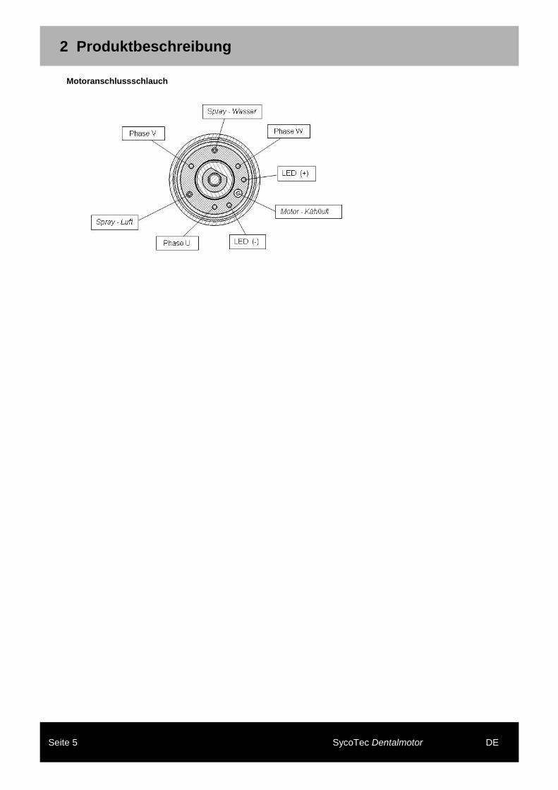
2 Produktbeschreibung
Motoranschlussschlauch
3 Wartung
Seite 6 SycoTec Dentalmotor DE
3 Wartung
Überprüfen von Störungen
Fehler: Behebung:
Das Medizinprodukt wird im Leerlauf zu warm Kühlluftmenge prüfen
O-Ring an dem Versorgungsschlauch fehlt O-Ring ersetzen
O-Ring am Kupplungsstück fehlt O-Ring ersetzen
Fehler: Behebung:
Das Medizinprodukt ist ohne Beleuchtung:
- LED Beleuchtung defekt bitte an Hersteller einsenden
- Beleuchtungssteuerung nicht aktiviert an der dentalen Behandlungseinheit prüfen
4 Einbau und Inbetriebnahme
Seite 7 SycoTec Dentalmotor DE
4 Einbau und Inbetriebnahme
Hinweis zum Einbau des Motors
• Der Dentalmotor ist nur zum Einbau in dentale Behandlungseinheiten bestimmt. • Die Bedingungen und Spezifikationen der Gebrauchsanweisung sind zu befolgen. • Beim Einbau oder Anbau an dentale Behandlungseinheiten, sind die nationalen Vorschriften und Gesetze zu
beachten. • Die Gerätesicherheitsprüfung nach DIN EN IEC 60601-1 und DIN EN IEC 60601-1-2 ist in Verbindung mit den
dentalen Behandlungseinheiten durchzuführen. • Der Dentalmotor darf nur an einer vom Hersteller zugelassenen Steuerung mit Strombegrenzung betrieben
werden. Schäden durch verschmutzte und feuchte Kühlluft
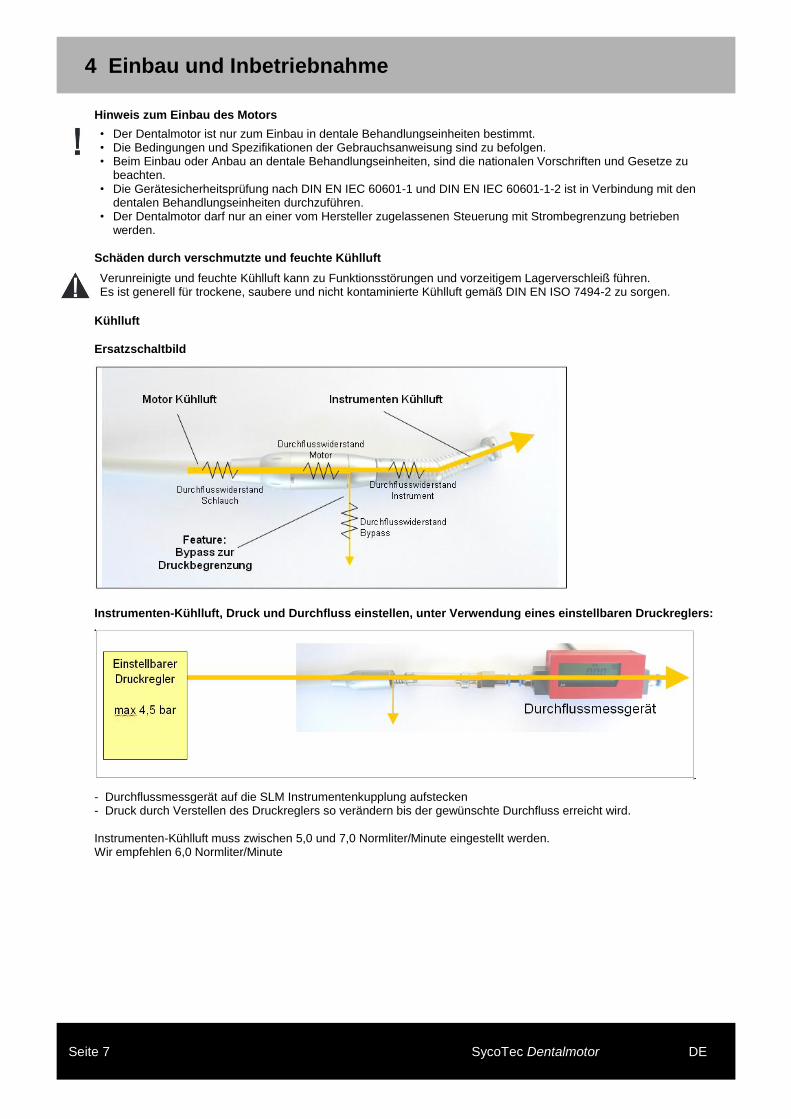
Verunreinigte und feuchte Kühlluft kann zu Funktionsstörungen und vorzeitigem Lagerverschleiß führen. Es ist generell für trockene, saubere und nicht kontaminierte Kühlluft gemäß DIN EN ISO 7494-2 zu sorgen.
Kühlluft
Ersatzschaltbild
Instrumenten-Kühlluft, Druck und Durchfluss einstellen, unter Verwendung eines einstellbaren Druckreglers:
- Durchflussmessgerät auf die SLM Instrumentenkupplung aufstecken - Druck durch Verstellen des Druckreglers so verändern bis der gewünschte Durchfluss erreicht wird. Instrumenten-Kühlluft muss zwischen 5,0 und 7,0 Normliter/Minute eingestellt werden. Wir empfehlen 6,0 Normliter/Minute
4 Einbau und Inbetriebnahme
Seite 8 SycoTec Dentalmotor DE
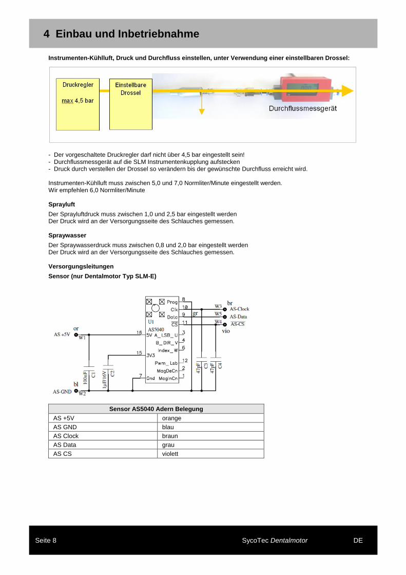
Instrumenten-Kühlluft, Druck und Durchfluss einstellen, unter Verwendung einer einstellbaren Drossel:
- Der vorgeschaltete Druckregler darf nicht über 4,5 bar eingestellt sein! - Durchflussmessgerät auf die SLM Instrumentenkupplung aufstecken - Druck durch verstellen der Drossel so verändern bis der gewünschte Durchfluss erreicht wird. Instrumenten-Kühlluft muss zwischen 5,0 und 7,0 Normliter/Minute eingestellt werden. Wir empfehlen 6,0 Normliter/Minute Sprayluft
Der Sprayluftdruck muss zwischen 1,0 und 2,5 bar eingestellt werden Der Druck wird an der Versorgungsseite des Schlauches gemessen. Spraywasser
Der Spraywasserdruck muss zwischen 0,8 und 2,0 bar eingestellt werden Der Druck wird an der Versorgungsseite des Schlauches gemessen. Versorgungsleitungen
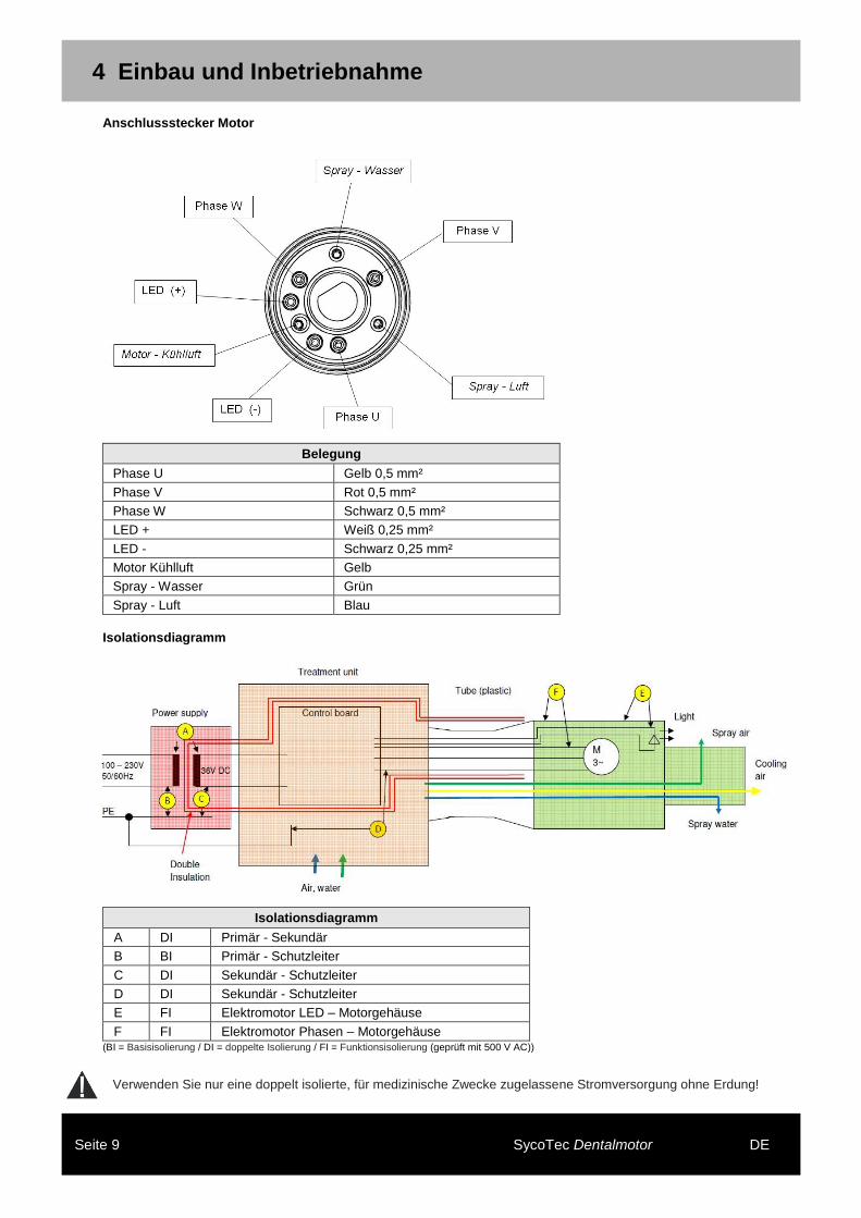
Sensor (nur Dentalmotor Typ SLM-E)
Sensor AS5040 Adern Belegung
AS +5V orange
AS GND blau
AS Clock braun
AS Data grau
AS CS violett
4 Einbau und Inbetriebnahme
Seite 9 SycoTec Dentalmotor DE
Anschlussstecker Motor
Belegung
Phase U Gelb 0,5 mm²
Phase V Rot 0,5 mm²
Phase W Schwarz 0,5 mm²
LED + Weiß 0,25 mm²
LED - Schwarz 0,25 mm²
Motor Kühlluft Gelb
Spray - Wasser Grün
Spray - Luft Blau
Isolationsdiagramm
Isolationsdiagramm
A DI Primär - Sekundär
B BI Primär - Schutzleiter
C DI Sekundär - Schutzleiter
D DI Sekundär - Schutzleiter
E FI Elektromotor LED – Motorgehäuse
F FI Elektromotor Phasen – Motorgehäuse (BI = Basisisolierung / DI = doppelte Isolierung / FI = Funktionsisolierung (geprüft mit 500 V AC))
Verwenden Sie nur eine doppelt isolierte, für medizinische Zwecke zugelassene Stromversorgung ohne Erdung!
5 Technische Daten
Seite 10 SycoTec Dentalmotor DE
5 Technische Daten
Elektrische Daten
Nennspannung 22,0 V
Leerlaufstrom 0,25 A
max. Drehzahl 40.000 min-1
EMK (Generatorspannung bei 40.000 min-1)
15,6 V
Drehmomentkonstante: 0,64 cm/A
max. Drehmoment 3,5 Ncm
Widerstand Ph-Ph 1,3 Ohm
Induktivität 0,33 mH
Einsatzzeiten (Kühlluft 10 Nl/min) Max. Dauermoment bei dem die Oberflächentemperatur des Motors 40 °C nicht übersteigt,
bezogen auf eine Umgebungstemperatur von 20 °C
0,6 Ncm unbegrenzt
1,0 Ncm 180 Sek.
2,0 Ncm 40 Sek.
3,0 Ncm 15 Sek.
3,5 Ncm 10 Sek.
Umgebungsbedingungen
Aufstellort Zulässig in Innenräumen (integriert in eine dentale Behandlungseinheit)
Umgebungstemperatur 10 – 35 °C (50 – 95 °F)
Relative Luftfeuchtigkeit 30 – 75 %
max. Betriebshöhe über NN 2.000 m
Lager- und Transportbedingungen
Transporttemperatur -30 – 70 °C (-22 – 158 °F)
Lagerungstemperatur 0 – 40 °C (32 – 104 °F)
Relative Luftfeuchtigkeit 15 – 93 %
Luftdruck 700 – 1.060 hPa
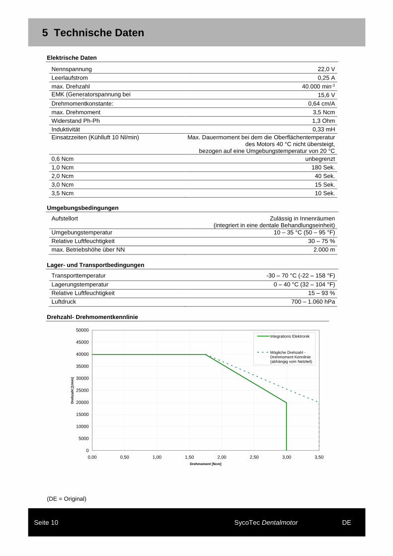
Drehzahl- Drehmomentkennlinie
(DE = Original)
Drehzahl - Drehmoment Kennlinie SLM
0
5000
10000
15000
20000
25000
30000
35000
40000
45000
50000
0,00 0,50 1,00 1,50 2,00 2,50 3,00 3,50
Drehmoment [Ncm]
Dre
hza
hl
[1/m
in]
Integrations Elektronik
Mögliche Drehzahl -Drehmoment Kennlinie(abhängig vom Netzteil)
1 User Information ...................................................................................................................................................... 4 Symbol Used............................................................................................................................................................ 4 Important Information ............................................................................................................................................... 4 Target Group............................................................................................................................................................ 4 Safety Check (STK) in According to EN 62353 ........................................................................................................ 4 Safety Precautions ................................................................................................................................................... 4 Intended Use - Purpose: .......................................................................................................................................... 4
2 Product Description .................................................................................................................................................. 5 Motor Connecting Hose ........................................................................................................................................... 5
3 Maintenance ............................................................................................................................................................ 6 Check for Malfunctions ............................................................................................................................................ 6
4 Installation and Commissioning ............................................................................................................................... 7 Instructions for installation of the dental motor ......................................................................................................... 7 Damage caused by contaminated and moist cooling air .......................................................................................... 7 Cooling Air ............................................................................................................................................................... 7 Spray Air .................................................................................................................................................................. 8 Spray Water ............................................................................................................................................................. 8 Supply Tube ............................................................................................................................................................. 8 Sensor (only dental motor type SLM-E) ................................................................................................................... 8 Connector to Motor .................................................................................................................................................. 9 Insulation diagram .................................................................................................................................................... 9
5 Specifications ......................................................................................................................................................... 10 Electrical Data ........................................................................................................................................................ 10 Ambient Conditions ................................................................................................................................................ 10 Storage and Transport Conditions ......................................................................................................................... 10 Speed / Torque diagram ........................................................................................................................................ 10
1 User Information
Page 4 SycoTec Dental Motor EN
1 User Information
Symbol Used
Situations where failure to follow the instructions may lead to danger, damage to material or operating faults.
Important information for operator and engineer
Important Information
• All in the operating manual of the dental motor given information have to be mind. • After long times (week-end, holidays, vacation) and before every treatment the drive system have to be purged at least
20 seconds. This have to be done with the connected dental treatment unit.
The technical specifications, illustrations and dimensions contained in these instructions are given only as a guide. They may not be the subject of any claim. The manufacturer reserves the right to make technical improvements to its equipment, without amending these instructions. For all additional information, please contact SycoTec. Target Group
This document is for installer and user. Safety Check (STK) in According to EN 62353
For this medical unit are following safety checks (STK) determined: - The dental motor must be common checked with the dental treatment unit. The check interval must be < 24 month. Checks for: • Motor or hose damaged on the outside. • If exist operator manual. • Leakage current in according to EN (IEC) 60601-1.
All results of the safety check must be documented in the medical device book
If defects that present a danger to patients, employees or third parties are identified during safety inspections, the device should not be used until the defects have been rectified through professional technical servicing.
Safety Precautions
Electrical shock with incorrectly connection of a third-party system to the medical device. When installing and operating the dental motor with treatment equipment and devices from other manufacturers, observe the provisions in "Protection against electrical shock," "Leakage current," and "Non-grounding the application part" in accordance with DIN EN IEC 60601-1.
Intended Use - Purpose:
This dental motor is: • Only intended for dental treatment. Any other type of use or alteration to the product is impermissible and can be
hazardous. • A dental motor according to relevant national statutory regulations. • A low-voltage electric dental motor in accordance with DIN EN ISO 14457 use of dental straight and contra angles
(according ISO 3964 short). • Not approved for use in areas with an increased risk of explosion.
According to these provisions, the dental motor is only to be used by an experienced user for the described application in accordance with: • The applicable health and safety regulations, • The applicable accident prevention regulations, • And this operating manual.
According to these regulations, the user is required to: • Use only equipment which is free of faults and works properly, • Use only the equipment for the proper purpose, • Protect himself, the patient and third parties from danger, • Avoid contamination from the product.
This dental motor is intended for following applications: • Indications: Dental motor 810 SLM-E: use for prophylaxis, preparation and endodontic treatment in dentistry. Dental motor 811 SLM-P: use for prophylaxis and preparation treatment in dentistry. • Contra indications: Dental motor 810 SLM-E / 811 SLM-P: not known • Adverse effects: Dental motor 810 SLM-E / 811 SLM-P: not known
2 Product Description
Page 5 SycoTec Dental Motor EN
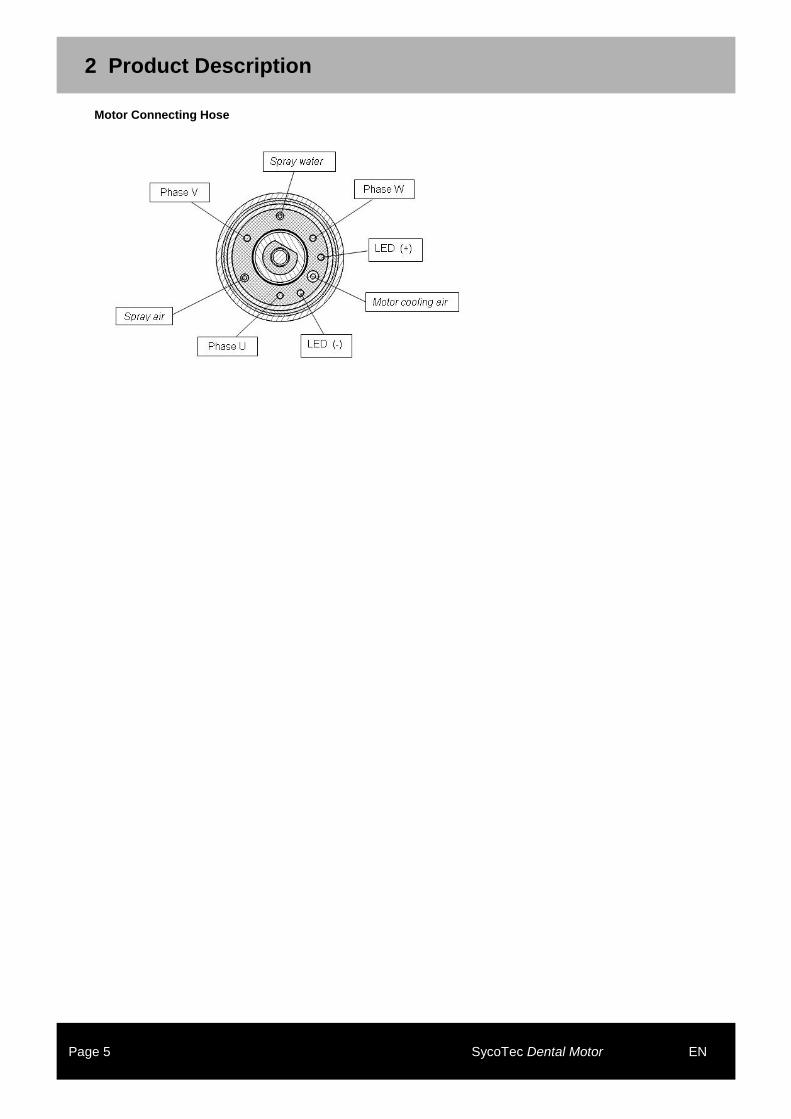
2 Product Description
Motor Connecting Hose
3 Maintenance
Page 6 SycoTec Dental Motor EN
3 Maintenance
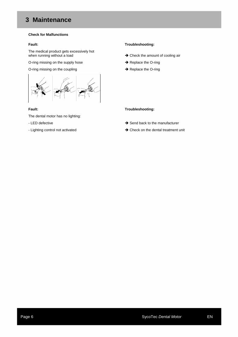
Check for Malfunctions
Fault: Troubleshooting:
The medical product gets excessively hot when running without a load Check the amount of cooling air
O-ring missing on the supply hose Replace the O-ring
O-ring missing on the coupling Replace the O-ring
Fault: Troubleshooting:
The dental motor has no lighting:
- LED defective Send back to the manufacturer
- Lighting control not activated Check on the dental treatment unit
4 Installation and Commissioning
Page 7 SycoTec Dental Motor EN
4 Installation and Commissioning
Instructions for installation of the dental motor
• The dental motor is only intended for installation in dental treatment units. • Follow all terms and specifications of the operating manual. • When installing and mounting to dental treatment units observe the provisions of national regulations and law. • The safety inspection of the motor in accordance to DIN EN IEC 60601-1 and DIN EN IEC 60601-1-2 have to
implement in conjunction with the dental treatment units. • Use only the dental motor with a control unit with current limiter approved by the manufacturer.
Damage caused by contaminated and moist cooling air
Contaminated and moist cooling air can cause malfunctions and premature bearing wear. In general, ensure that a dry, clean and uncontaminated supply of cooling air is provided in accordance with DIN EN ISO 7494-2.
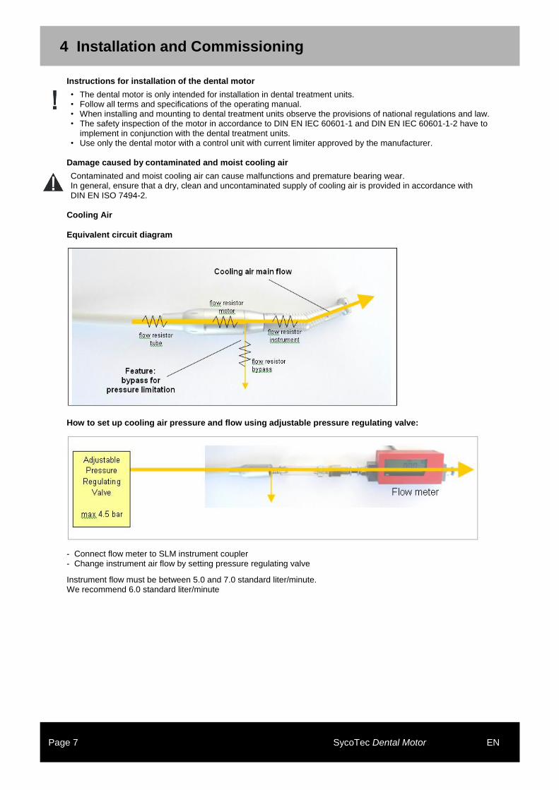
Cooling Air
Equivalent circuit diagram
How to set up cooling air pressure and flow using adjustable pressure regulating valve:
- Connect flow meter to SLM instrument coupler - Change instrument air flow by setting pressure regulating valve
Instrument flow must be between 5.0 and 7.0 standard liter/minute. We recommend 6.0 standard liter/minute
4 Installation and Commissioning
Page 8 SycoTec Dental Motor EN
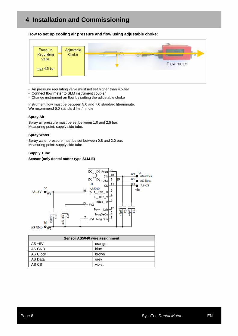
How to set up cooling air pressure and flow using adjustable choke:
- Air pressure regulating valve must not set higher than 4.5 bar - Connect flow meter to SLM instrument coupler - Change instrument air flow by setting the adjustable choke
Instrument flow must be between 5.0 and 7.0 standard liter/minute. We recommend 6.0 standard liter/minute
Spray Air
Spray air pressure must be set between 1.0 and 2.5 bar. Measuring point: supply side tube. Spray Water
Spray water pressure must be set between 0.8 and 2.0 bar. Measuring point: supply side tube. Supply Tube
Sensor (only dental motor type SLM-E)
Sensor AS5040 wire assignment
AS +5V orange
AS GND blue
AS Clock brown
AS Data grey
AS CS violet
4 Installation and Commissioning
Page 9 SycoTec Dental Motor EN
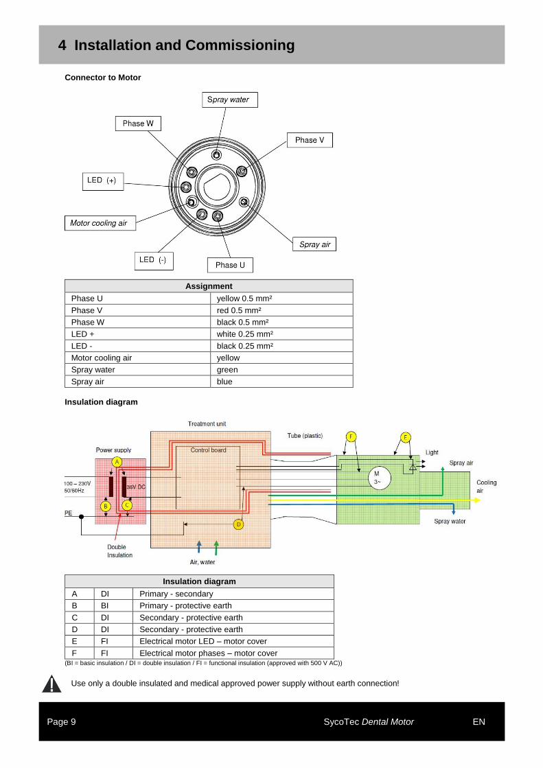
Connector to Motor
Assignment
Phase U yellow 0.5 mm²
Phase V red 0.5 mm²
Phase W black 0.5 mm²
LED + white 0.25 mm²
LED - black 0.25 mm²
Motor cooling air yellow
Spray water green
Spray air blue
Insulation diagram
Insulation diagram
A DI Primary - secondary
B BI Primary - protective earth
C DI Secondary - protective earth
D DI Secondary - protective earth
E FI Electrical motor LED – motor cover
F FI Electrical motor phases – motor cover (BI = basic insulation / DI = double insulation / FI = functional insulation (approved with 500 V AC))
Use only a double insulated and medical approved power supply without earth connection!
5 Specifications
Page 10 SycoTec Dental Motor EN
5 Specifications
Electrical Data
Nominal voltage 22.0 V
No load current 0.25 A
Max. speed 40,000 rpm
Back emf (at 40,000 rpm) 15.6 V
Torque constant 0.64 Ncm/A
Max. torque 3.5 Ncm
Resistance Ph-Ph 1.3 Ohm
Inductance 0.33 mH
Operating times (cooling air 10 standard liter/min)
Maximum continuous duration not exceeding 40°C on surface of motor at ambient temperature 20°C
0.6 Ncm without limit
1.0 Ncm 180 s
2.0 Ncm 40 s
3.0 Ncm 15 s
3.5 Ncm 10 s
Ambient Conditions
Location Permitted in interior rooms (integrated in a dental treatment unit)