27
Bedienungsanleitung manual Manual de instrucción Amateurfunk Mobilfunkgerät amateur mobile radio Transceptor para radioaficionados 28 - 29,6990 MHz

Bedienungsanleitungmanual
Manual de instrucción
Amateurfunk Mobilfunkgerätamateur mobile radioTransceptor para radioaficionados
28 - 29,6990 MHz
HAM_MobileCom-1011_small-Dim:Layout 1 9/10/2014 12:39 PM Seite 1
2 3
Wir gratulieren Ihnen zum Kauf des TEAM HAM MobileCom 1011. Sie haben ein hochwertiges, solidesAmateurfunkgerät erworben, das den professionellen Ansprüchen der Funkkommunikation gerecht wird. Die Leistungsfähigkeit und die Qualität des HAM MobileCom 1011, welches die neuesten Technologien be-inhaltet, werden Sie zufrieden stellen.
Um die volle Funktionalität des HAM MobileCom 1011 kennenzulernen und um eine sachgemäße Behandlungund Bedienung zu garantieren, bitten wir Sie diese Bedienungsanleitung zu lesen.
Das HAM MobileCom 1011 ist ein Amateurfunkgerät und darf nur von lizenzierten Amateurfunkern betrieben werden.Die Einhaltung der Lizenzbestimmungen liegt in der Eigenverantwortlichkeit des Amateurfunkers.
VORSICHTMASSNAHMEN
Bitte beachten Sie die folgenden Vorsichtsmaßnahmen um Verletzungen, Feuer oder Schäden am Gerät zu vermeiden.
Zu langes Senden oder übermäßig langer Gebrauch mit hoher Sendeleistung führt zu Erhitzung am hinteren Teil des Funkgerätes.
Achten Sie darauf, dass Sie das Gerät nie für längere Zeit direktem Sonnenlicht oder anderen Hitzequellen aussetzen.
Vermeiden Sie staubige oder feuchten Plätze für das HAM MobileCom 1011.
Sollten Sie eine außergewöhnlichen Geruch oder Rauch feststellen, schalten Sie das Gerät sofort aus und kontaktierenIhren Fachhändler.
Modifizieren Sie das Gerät unter keinen Umständen.
Lassen Sie Service- und Reparaturarbeiten nur von einem qualifizierten Fachhändler ausführen.
HINWEIS : Bevor Sie dieses Gerät benutzen, lesen Sie bitte diese Bedienungsanleitung.
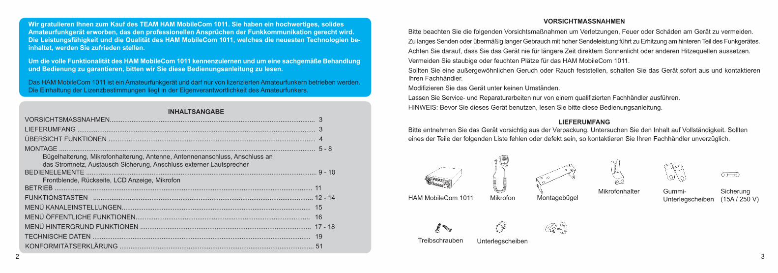
LIEFERUMFANGBitte entnehmen Sie das Gerät vorsichtig aus der Verpackung. Untersuchen Sie den Inhalt auf Vollständigkeit. Sollteneines der Teile der folgenden Liste fehlen oder defekt sein, so kontaktieren Sie Ihren Fachhändler unverzüglich.
HAM MobileCom 1011 Mikrofon
Treibschrauben Unterlegscheiben
Mikrofonhalter Gummi-Unterlegscheiben
Sicherung (15A / 250 V)Montagebügel
INHALTSANGABEVORSICHTSMASSNAHMEN................................................................................................................. 3
LIEFERUMFANG ................................................................................................................................... 3
ÜBERSICHT FUNKTIONEN .................................................................................................................. 4
MONTAGE ............................................................................................................................................. 5 - 8Bügelhalterung, Mikrofonhalterung, Antenne, Antennenanschluss, Anschluss an das Stromnetz, Austausch Sicherung, Anschluss externer Lautsprecher
BEDIENELEMENTE ............................................................................................................................... 9 - 10Frontblende, Rückseite, LCD Anzeige, Mikrofon
BETRIEB .............................................................................................................................................. 11
FUNKTIONSTASTEN ......................................................................................................................... 12 - 14
MENÜ KANALEINSTELLUNGEN........................................................................................................ 15
MENÜ ÖFFENTLICHE FUNKTIONEN................................................................................................ 16
MENÜ HINTERGRUND FUNKTIONEN .............................................................................................. 17 - 18
TECHNISCHE DATEN ........................................................................................................................ 19
KONFORMITÄTSERKLÄRUNG ........................................................................................................... 51
HAM_MobileCom-1011_small-Dim:Layout 1 9/10/2014 12:39 PM Seite 2
4 5
ÜBERSICHT FUNKTIONEN
1. LCD Anzeige; Kanal-Nr. / Frequenz und andere Funktionen2. Betriebsarten: PA / AM / FM / USB / LSB 3. Frequenzraster 10HZ, 100HZ, 100Khz, 1MHz4. ± 1.5KHz Feinjustierung (Clarifier)5. Menü Funktionen 6. ECHO Funktion7. SQ, ASQ Rauschsperre-Funktion (nur FM und AM) 8. RF GAIN; Empfangssignalstärke regelbar9. RF PWR; Sendeleistung regelbar
10. SCAN; Kanalsuchlauf11. programmierbare Raster-Auflösung (RB)12. NB (Noise Blanker - Geräuschfilter/
ANL (Automatic Noise Limiter - autom. Frequenzbegrenzung) 13. DW, Zweikanalüberwachung 14. BEEP, Warnton15. +10KHZ, Frequenzablage16. SWR, S/RF; Stehwellenanzeige17. TOT, Sendezeitbegrenzung18. HI-CUT (Empfangstonart) 19. EMG CALL, Notruf20. SWR PROTECTION, SWR-Schutz21. Überladeschutz22. Tastatursperre23. sieben LCD Hintergrundfarben24. 10 Speicherbänke mit jeweils max. 40 Kanälen (via Software programmierbar)26. PC-Programmierung mit optionaler Software möglich
MONTAGE
Wählen Sie den Standort des HAM MobileCom 1011 in Ihrem Fahrzeug nach den Kriterien der besten und einfachstenBedienbarkeit. Das montierte Gerät darf unter keinen Umständen den Fahrer in seiner Bewegungsfreiheit in irgendeinerWeise behindern oder einschränken.
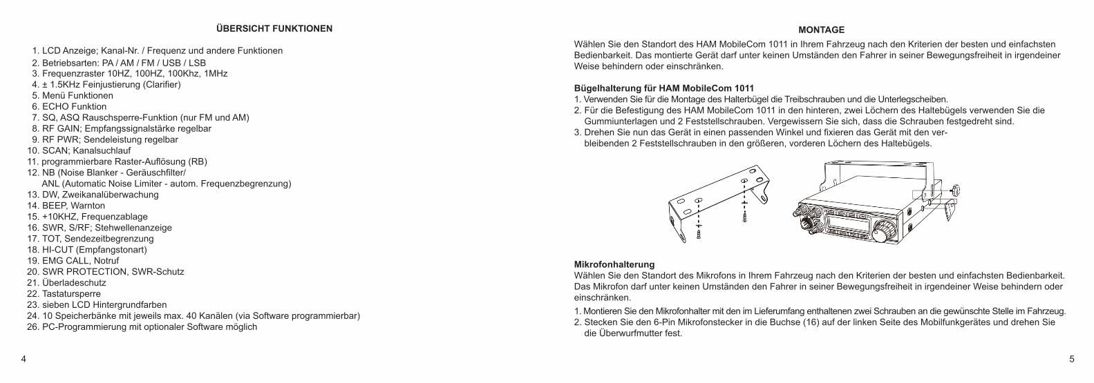
Bügelhalterung für HAM MobileCom 10111. Verwenden Sie für die Montage des Halterbügel die Treibschrauben und die Unterlegscheiben. 2. Für die Befestigung des HAM MobileCom 1011 in den hinteren, zwei Löchern des Haltebügels verwenden Sie die
Gummiunterlagen und 2 Feststellschrauben. Vergewissern Sie sich, dass die Schrauben festgedreht sind. 3. Drehen Sie nun das Gerät in einen passenden Winkel und fixieren das Gerät mit den ver-
bleibenden 2 Feststellschrauben in den größeren, vorderen Löchern des Haltebügels.
MikrofonhalterungWählen Sie den Standort des Mikrofons in Ihrem Fahrzeug nach den Kriterien der besten und einfachsten Bedienbarkeit.Das Mikrofon darf unter keinen Umständen den Fahrer in seiner Bewegungsfreiheit in irgendeiner Weise behindern odereinschränken.
1. Montieren Sie den Mikrofonhalter mit den im Lieferumfang enthaltenen zwei Schrauben an die gewünschte Stelle im Fahrzeug.2. Stecken Sie den 6-Pin Mikrofonstecker in die Buchse (16) auf der linken Seite des Mobilfunkgerätes und drehen Sie
die Überwurfmutter fest.
HAM_MobileCom-1011_small-Dim:Layout 1 9/10/2014 12:39 PM Seite 4

6 7
Antenne Die Antenne gehört zu den wichtigsten Teilen einer Funkanlage. Die Wahl der Antenne und des Montageortes ist von gro-ßer Bedeutung für die maximale Reichweite Ihrer Funkanlage. Die folgenden Kriterien sollten Sie bei der Wahl des Anten-nenstandortes und der Montage berücksichtigen.
Allgemein gilt :
> Die Antenne muss für den Funkbetrieb im entsprechenden Frequenzbereich geeignet sein. > Der Standort der Antenne sollte möglichst hoch und unverbaut sein. > Das Antennenkabel sollte unbeschädigt, und die Stecker ordnungsgemäß angeschlossen sein. > Das Antennenkabel sollte nicht zu stark geknickt werden. > Antennen mit einer größeren mechanischen Länge erzielen bessere Reichweiten.
Bei der Montage von Mobilantennen ist folgendes zu beachten:
> Die Antenne sollte in der Mitte eines größeren Karosserieteils montiert werden. > Der Antennenfuß sollte möglichst Kontakt zu einer leitenden Metallfläche des Karosseriebleches haben.
Außer der Festmontage, bei der ein Loch in die Karosserie Ihres Fahrzeuges gebohrt werden muss, gibt es noch weitereMöglichkeiten der Befestigung, z.B. mit einem Kofferraumdeckel-Klemmhalter oder einem Magnetfuß.
> Um Störungen bei Radio- und Fernsehempfang zu vermeiden, sollte die Funkantenne nicht in unmittelbarer Nähe der Radio- und Fernsehantenne montiert werden.
> Alle angeschlossenen Leitungen, einschließlich der Antennenleitung, dürfen nur eine Länge von max. 3 Metern haben.
Achten Sie auf die korrekte Installation der Funkanlage. WARNUNG:▲ Verwenden Sie nur eine passende Antenne, welche den Anforderungen des HAM MobileCom 1011 entspricht.
Bei Fragen kontaktieren Sie bitte Ihren Händler. ▲ Achten Sie auf die korrekte Erdung der Antenne.▲ Vor dem ersten Betrieb muss die Antenne angeschlossen werden um mögliche Schäden an der Endstufe des HAM
MobileCom 1011 zu vermeiden.
Für die optimale Erdung der Antenne empfehlen wir folgende Platzierungen:
AntennenanschlussBefestigen Sie den PL-Antennestecker in der Antennenbuchse (20), welche sich auf der Rückseite des Gerätes befindet.
Ebenso ist auf eine ordentliche Verbindung des Antennenkabels mit dem Antennenfuß zuachten. Nicht einwandfreie Verbindungen können zu einem Defekt des Gerätes führen unddie Funkreichweite erheblich verringern. Die Antennenanlage (nicht im Lieferumfang ent-halten) sollte sehr gut an das Funkgerät angepasst sein, ansonsten wird ein Teil der Sen-deleistung an der Antenne reflektiert und nicht abgestrahlt. Das führt ebenfalls zu einergeringeren Reichweite der Funkanlage.
Anschluss an das StromnetzHinweis:Die Spannung muss 13,8 V DC, mit negativer Erdung betragen. Stellen Sie sicher, dass die positive ( +, rot ) und nega-tive ( -, schwarz ) Polarität korrekt ist, bevor Sie das Gerät anschließen. Der Stromanschluss an das KFZ-Bordnetz mussdurch einen Fachmann erfolgen.
Schliessen Sie das Netzkabel direkt an die Autobatterie an. Verwenden Sie keinen Zigarettenanzünder-Adapter, da dieserAnschluss nicht über genügend Stromstärke für den Betrieb des Gerätes verfügt. Achten Sie auf die korrekte Polarität derKabel beim Anschließen an die Batterie.
ACHTUNG> Vor Anschluss des Stromversorgungskabels an die Batterie entfernen Sie bitte alle negativen Zuleitungen zur Batterie.
Nach abgeschlossener Montage und Verkabelung überprüfen Sie bitte noch einmal den korrekten Anschluss, bevor Sie das negative Anschlusskabel mit der Batterie verbinden.
> Wenn die Sicherung offen ist, überprüfen diese auf mögliche Schäden. Im Falle eines Defekts, ersetzen Sie diese bitte.
HAM_MobileCom-1011_small-Dim:Layout 1 9/10/2014 12:39 PM Seite 6
8 9
Austausch Sicherung Das Gerät benötigt eine 15A / 250V Sicherung.Sollte die Sicherung durchbrennen, finden Sie die Ursache und beheben Sie den Fehler. Danach tauschen Sie die Siche-rung aus. Sollte die Sicherung wieder durchbrennen, unterbrechen Sie die Kabelverbindung und kontaktieren Sie IhrenHändler.
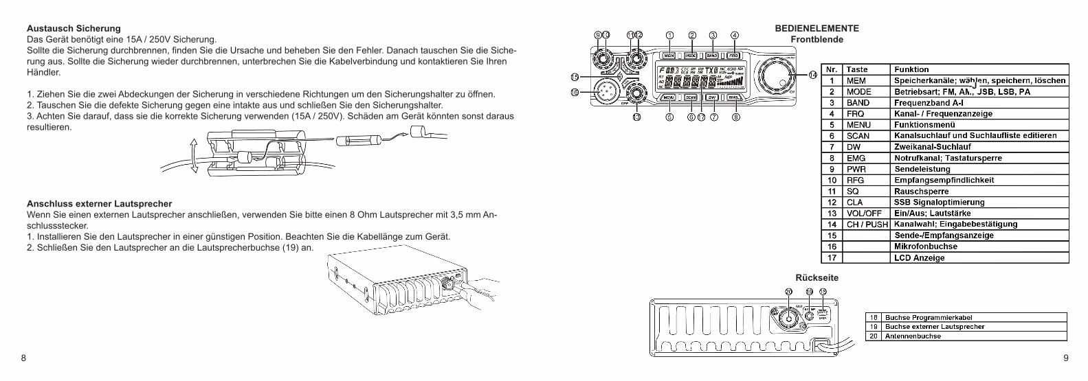
1. Ziehen Sie die zwei Abdeckungen der Sicherung in verschiedene Richtungen um den Sicherungshalter zu öffnen. 2. Tauschen Sie die defekte Sicherung gegen eine intakte aus und schließen Sie den Sicherungshalter. 3. Achten Sie darauf, dass sie die korrekte Sicherung verwenden (15A / 250V). Schäden am Gerät könnten sonst darausresultieren.
Anschluss externer LautsprecherWenn Sie einen externen Lautsprecher anschließen, verwenden Sie bitte einen 8 Ohm Lautsprecher mit 3,5 mm An-schlussstecker. 1. Installieren Sie den Lautsprecher in einer günstigen Position. Beachten Sie die Kabellänge zum Gerät. 2. Schließen Sie den Lautsprecher an die Lautsprecherbuchse (19) an.
-J
BEDIENELEMENTEFrontblende
Rückseite
HAM_MobileCom-1011_small-Dim:Layout 1 9/10/2014 12:39 PM Seite 8
10 11
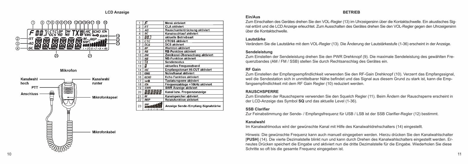
LCD Anzeige
Mikrofon
BETRIEBEin/AusZum Einschalten des Gerätes drehen Sie den VOL-Regler (13) im Uhrzeigersinn über die Kontaktschwelle. Ein akustisches Sig-nal ertönt und die LCD Anzeige erleuchtet. Zum Ausschalten des Gerätes drehen Sie den VOL-Regler gegen den Uhrzeigersinnüber die Kontaktschwelle.
Lautstärke Verändern Sie die Lautstärke mit dem VOL-Regler (13). Die Änderung der Lautstärkestufe (1-36) erscheint in der Anzeige.
Sendeleistung Zum Einstellen der Sendeleistung drehen Sie den PWR Drehknopf (9). Die maximale Sendeleistung des gewählten Fre-quenzbandes (AM / FM / SSB) stellen Sie durch Rechtsanschlag des Gerätes ein.
RF Gain Zum Einstellen der Empfangsempfindlichkeit verwenden Sie den RF-Gain Drehknopf (10). Verzerrt das Empfangssignal,weil die Sendestation sich in unmittelbarer Nähe befindet und das Signal aus diesem Grund zu stark ist, kann die Emp-fangsempfindlichkeit mit dem RF Gain Regler (10) reduziert werden.
RAUSCHSPERRE Zum Einstellen der Rauschsperre verwenden Sie den Squelch Regler (11). Beim Ändern der Rauschsperre erscheint inder LCD-Anzeige das Symbol SQ und das aktuelle Level (1-36).
SSB Clarifier Zur Feinabstimmung der Sende- / Empfangsfrequenz für USB / LSB ist der SSB Clarifier-Regler (12) bestimmt.
Kanalwahl Im Kanalwahlmodus wird der gewünschte Kanal mit Hilfe des Kanalwahldrehschalters (14) eingestellt.
Hinweis: Die gewünschte Frequenz kann auch manuell eingegeben werden. Hierzu drücken Sie den Kanalwahlschalter[PUSH] (14). Die vierte Dezimalstelle blinkt nun und kann durch Drehen des Kanalwahlschalters eingestellt werden. Er-neutes Drücken speichert die Eingabe und aktiviert nun die dritte Dezimalstelle für die Eingabe. Wiederholen Sie dieseSchritte so oft bis die gesamte Frequenz eingegeben ist.
HAM_MobileCom-1011_small-Dim:Layout 1 9/10/2014 12:39 PM Seite 10
12 13
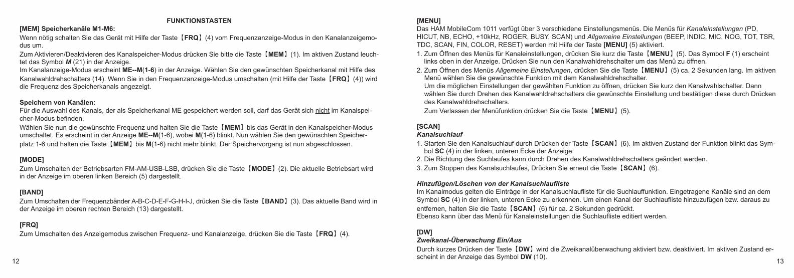
FUNKTIONSTASTEN[MEM] Speicherkanäle M1-M6:Wenn nötig schalten Sie das Gerät mit Hilfe der Taste【FRQ】(4) vom Frequenzanzeige-Modus in den Kanalanzeigemo-dus um. Zum Aktivieren/Deaktivieren des Kanalspeicher-Modus drücken Sie bitte die Taste【MEM】(1). Im aktiven Zustand leuch-tet das Symbol M (21) in der Anzeige. Im Kanalanzeige-Modus erscheint ME--M(1-6) in der Anzeige. Wählen Sie den gewünschten Speicherkanal mit Hilfe desKanalwahldrehschalters (14). Wenn Sie in den Frequenzanzeige-Modus umschalten (mit Hilfe der Taste【FRQ】(4)) wirddie Frequenz des Speicherkanals angezeigt.
Speichern von Kanälen:Für die Auswahl des Kanals, der als Speicherkanal ME gespeichert werden soll, darf das Gerät sich nicht im Kanalspei-cher-Modus befinden. Wählen Sie nun die gewünschte Frequenz und halten Sie die Taste【MEM】bis das Gerät in den Kanalspeicher-Modusumschaltet. Es erscheint in der Anzeige ME--M(1-6), wobei M(1-6) blinkt. Nun wählen Sie den gewünschten Speicher-platz 1-6 und halten die Taste【MEM】bis M(1-6) nicht mehr blinkt. Der Speichervorgang ist nun abgeschlossen.
[MODE]Zum Umschalten der Betriebsarten FM-AM-USB-LSB, drücken Sie die Taste【MODE】(2). Die aktuelle Betriebsart wirdin der Anzeige im oberen linken Bereich (5) dargestellt.
[BAND]Zum Umschalten der Frequenzbänder A-B-C-D-E-F-G-H-I-J, drücken Sie die Taste【BAND】(3). Das aktuelle Band wird inder Anzeige im oberen rechten Bereich (13) dargestellt.
[FRQ]Zum Umschalten des Anzeigemodus zwischen Frequenz- und Kanalanzeige, drücken Sie die Taste【FRQ】(4).
[MENU]Das HAM MobileCom 1011 verfügt über 3 verschiedene Einstellungsmenüs. Die Menüs für Kanaleinstellungen (PD,HICUT, NB, ECHO, +10kHz, ROGER, BUSY, SCAN) und Allgemeine Einstellungen (BEEP, INDIC, MIC, NOG, TOT, TSR,TDC, SCAN, FIN, COLOR, RESET) werden mit Hilfe der Taste [MENU] (5) aktiviert.1. Zum Öffnen des Menüs für Kanaleinstellungen, drücken Sie kurz die Taste【MENU】(5). Das Symbol F (1) erscheint
links oben in der Anzeige. Drücken Sie nun den Kanalwahldrehschalter um das Menü zu öffnen. 2. Zum Öffnen des Menüs Allgemeine Einstellungen, drücken Sie die Taste【MENU】(5) ca. 2 Sekunden lang. Im aktiven
Menü wählen Sie die gewünschte Funktion mit dem Kanalwahldrehschalter. Um die möglichen Einstellungen der gewählten Funktion zu öffnen, drücken Sie kurz den Kanalwahlschalter. Dannwählen Sie durch Drehen des Kanalwahldrehschalters die gewünschte Einstellung und bestätigen diese durch Drückendes Kanalwahldrehschalters. Zum Verlassen der Menüfunktion drücken Sie die Taste【MENU】(5).
[SCAN]Kanalsuchlauf 1. Starten Sie den Kanalsuchlauf durch Drücken der Taste【SCAN】(6). Im aktiven Zustand der Funktion blinkt das Sym-
bol SC (4) in der linken, unteren Ecke der Anzeige. 2. Die Richtung des Suchlaufes kann durch Drehen des Kanalwahldrehschalters geändert werden. 3. Zum Stoppen des Kanalsuchlaufes, Drücken Sie erneut die Taste【SCAN】(6).
Hinzufügen/Löschen von der KanalsuchlauflisteIm Kanalmodus gelten die Einträge in der Kanalsuchlaufliste für die Suchlauffunktion. Eingetragene Kanäle sind an demSymbol SC (4) in der linken, unteren Ecke zu erkennen. Um einen Kanal der Suchlaufliste hinzuzufügen bzw. daraus zuentfernen, halten Sie die Taste【SCAN】(6) für ca. 2 Sekunden gedrückt.Ebenso kann über das Menü für Kanaleinstellungen die Suchlaufliste editiert werden.
[DW]Zweikanal-Überwachung Ein/AusDurch kurzes Drücken der Taste【DW】wird die Zweikanalüberwachung aktiviert bzw. deaktiviert. Im aktiven Zustand er-scheint in der Anzeige das Symbol DW (10).
HAM_MobileCom-1011_small-Dim:Layout 1 9/10/2014 12:39 PM Seite 12
14 15
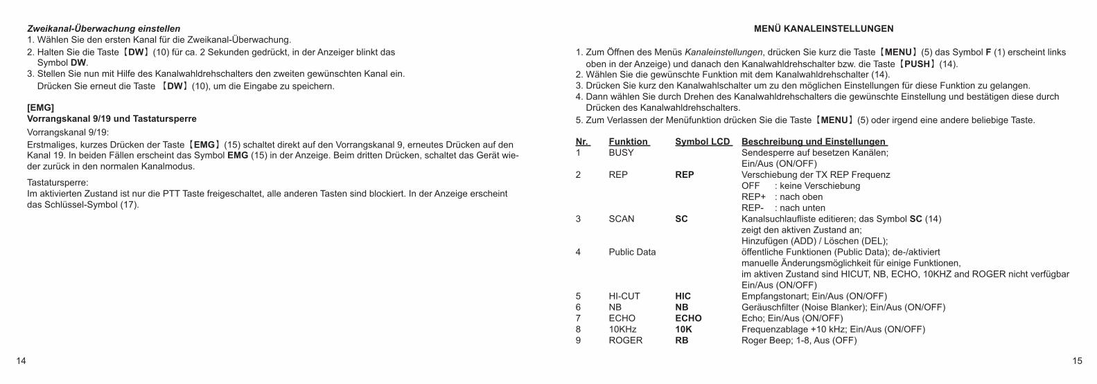
Zweikanal-Überwachung einstellen1. Wählen Sie den ersten Kanal für die Zweikanal-Überwachung. 2. Halten Sie die Taste【DW】(10) für ca. 2 Sekunden gedrückt, in der Anzeiger blinkt das
Symbol DW.3. Stellen Sie nun mit Hilfe des Kanalwahldrehschalters den zweiten gewünschten Kanal ein.
Drücken Sie erneut die Taste 【DW】(10), um die Eingabe zu speichern.
[EMG]Vorrangskanal 9/19 und Tastatursperre
Vorrangskanal 9/19:Erstmaliges, kurzes Drücken der Taste【EMG】(15) schaltet direkt auf den Vorrangskanal 9, erneutes Drücken auf denKanal 19. In beiden Fällen erscheint das Symbol EMG (15) in der Anzeige. Beim dritten Drücken, schaltet das Gerät wie-der zurück in den normalen Kanalmodus.
Tastatursperre:Im aktivierten Zustand ist nur die PTT Taste freigeschaltet, alle anderen Tasten sind blockiert. In der Anzeige erscheintdas Schlüssel-Symbol (17).
MENÜ KANALEINSTELLUNGEN
1. Zum Öffnen des Menüs Kanaleinstellungen, drücken Sie kurz die Taste【MENU】(5) das Symbol F (1) erscheint links oben in der Anzeige) und danach den Kanalwahldrehschalter bzw. die Taste【PUSH】(14).
2. Wählen Sie die gewünschte Funktion mit dem Kanalwahldrehschalter (14). 3. Drücken Sie kurz den Kanalwahlschalter um zu den möglichen Einstellungen für diese Funktion zu gelangen. 4. Dann wählen Sie durch Drehen des Kanalwahldrehschalters die gewünschte Einstellung und bestätigen diese durch
Drücken des Kanalwahldrehschalters. 5. Zum Verlassen der Menüfunktion drücken Sie die Taste【MENU】(5) oder irgend eine andere beliebige Taste.
Nr. Funktion Symbol LCD Beschreibung und Einstellungen 1 BUSY Sendesperre auf besetzen Kanälen;
Ein/Aus (ON/OFF)2 REP REP Verschiebung der TX REP Frequenz
OFF : keine VerschiebungREP+ : nach obenREP- : nach unten
3 SCAN SC Kanalsuchlaufliste editieren; das Symbol SC (14) zeigt den aktiven Zustand an; Hinzufügen (ADD) / Löschen (DEL);
4 Public Data öffentliche Funktionen (Public Data); de-/aktiviertmanuelle Änderungsmöglichkeit für einige Funktionen,im aktiven Zustand sind HICUT, NB, ECHO, 10KHZ and ROGER nicht verfügbarEin/Aus (ON/OFF)
5 HI-CUT HIC Empfangstonart; Ein/Aus (ON/OFF) 6 NB NB Geräuschfilter (Noise Blanker); Ein/Aus (ON/OFF) 7 ECHO ECHO Echo; Ein/Aus (ON/OFF) 8 10KHz 10K Frequenzablage +10 kHz; Ein/Aus (ON/OFF) 9 ROGER RB Roger Beep; 1-8, Aus (OFF)
HAM_MobileCom-1011_small-Dim:Layout 1 9/10/2014 12:39 PM Seite 14
16 17
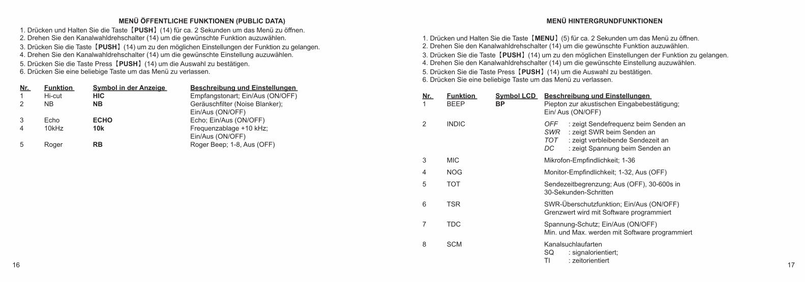
MENÜ ÖFFENTLICHE FUNKTIONEN (PUBLIC DATA)1. Drücken und Halten Sie die Taste【PUSH】(14) für ca. 2 Sekunden um das Menü zu öffnen.2. Drehen Sie den Kanalwahldrehschalter (14) um die gewünschte Funktion auzuwählen. 3. Drücken Sie die Taste【PUSH】(14) um zu den möglichen Einstellungen der Funktion zu gelangen.4. Drehen Sie den Kanalwahldrehschalter (14) um die gewünschte Einstellung auzuwählen. 5. Drücken Sie die Taste Press【PUSH】(14) um die Auswahl zu bestätigen. 6. Drücken Sie eine beliebige Taste um das Menü zu verlassen.
Nr. Funktion Symbol in der Anzeige Beschreibung und Einstellungen 1 Hi-cut HIC Empfangstonart; Ein/Aus (ON/OFF) 2 NB NB Geräuschfilter (Noise Blanker);
Ein/Aus (ON/OFF)3 Echo ECHO Echo; Ein/Aus (ON/OFF) 4 10kHz 10k Frequenzablage +10 kHz;
Ein/Aus (ON/OFF) 5 Roger RB Roger Beep; 1-8, Aus (OFF)
MENÜ HINTERGRUNDFUNKTIONEN
1. Drücken und Halten Sie die Taste【MENU】(5) für ca. 2 Sekunden um das Menü zu öffnen. 2. Drehen Sie den Kanalwahldrehschalter (14) um die gewünschte Funktion auzuwählen. 3. Drücken Sie die Taste【PUSH】(14) um zu den möglichen Einstellungen der Funktion zu gelangen. 4. Drehen Sie den Kanalwahldrehschalter (14) um die gewünschte Einstellung auzuwählen. 5. Drücken Sie die Taste Press【PUSH】(14) um die Auswahl zu bestätigen. 6. Drücken Sie eine beliebige Taste um das Menü zu verlassen.
Nr. Funktion Symbol LCD Beschreibung und Einstellungen 1 BEEP BP Piepton zur akustischen Eingabebestätigung;
Ein/ Aus (ON/OFF)
2 INDIC OFF : zeigt Sendefrequenz beim Senden anSWR : zeigt SWR beim Senden anTOT : zeigt verbleibende Sendezeit anDC : zeigt Spannung beim Senden an
3 MIC Mikrofon-Empfindlichkeit; 1-36
4 NOG Monitor-Empfindlichkeit; 1-32, Aus (OFF)
5 TOT Sendezeitbegrenzung; Aus (OFF), 30-600s in 30-Sekunden-Schritten
6 TSR SWR-Überschutzfunktion; Ein/Aus (ON/OFF) Grenzwert wird mit Software programmiert
7 TDC Spannung-Schutz; Ein/Aus (ON/OFF) Min. und Max. werden mit Software programmiert
8 SCM KanalsuchlaufartenSQ : signalorientiert;TI : zeitorientiert
HAM_MobileCom-1011_small-Dim:Layout 1 9/10/2014 12:39 PM Seite 16
18 19
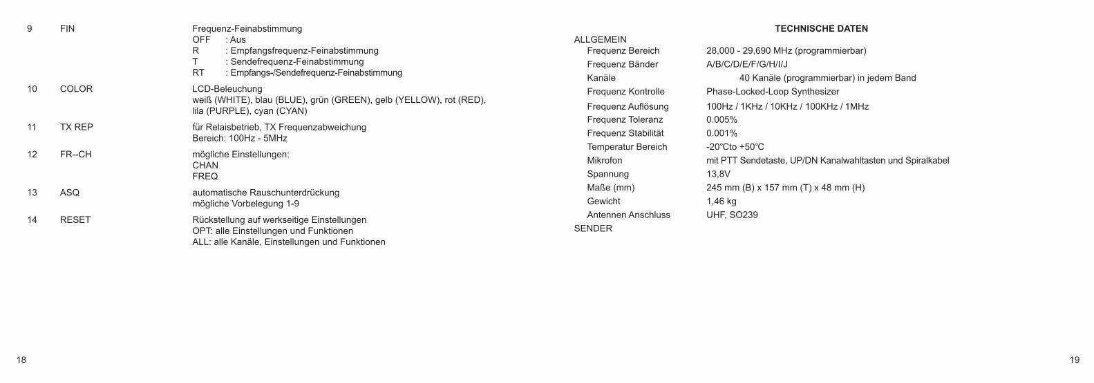
9 FIN Frequenz-FeinabstimmungOFF : AusR : Empfangsfrequenz-FeinabstimmungT : Sendefrequenz-FeinabstimmungRT : Empfangs-/Sendefrequenz-Feinabstimmung
10 COLOR LCD-Beleuchungweiß (WHITE), blau (BLUE), grün (GREEN), gelb (YELLOW), rot (RED), lila (PURPLE), cyan (CYAN)
11 TX REP für Relaisbetrieb, TX Frequenzabweichung Bereich: 100Hz - 5MHz
12 FR--CH mögliche Einstellungen:CHANFREQ
13 ASQ automatische Rauschunterdrückungmögliche Vorbelegung 1-9
14 RESET Rückstellung auf werkseitige EinstellungenOPT: alle Einstellungen und Funktionen
ALL: alle Kanäle, Einstellungen und Funktionen
TECHNISCHE DATENALLGEMEIN
Frequenz Bereich 28,000 - 29,690 MHz (programmierbar)
Frequenz Bänder A/B/C/D/E/F/G/H/I/J
Kanäle 40 Kanäle (programmierbar) in jedem Band
Frequenz Kontrolle Phase-Locked-Loop Synthesizer
Frequenz Auflösung 100Hz / 1KHz / 10KHz / 100KHz / 1MHz
Frequenz Toleranz 0.005%
Frequenz Stabilität 0.001%
Temperatur Bereich -20℃to +50℃
Mikrofon mit PTT Sendetaste, UP/DN Kanalwahltasten und Spiralkabel
Spannung 13,8V
Maße (mm) 245 mm (B) x 157 mm (T) x 48 mm (H)
Gewicht 1,46 kg
Antennen Anschluss UHF, SO239
SENDER
HAM_MobileCom-1011_small-Dim:Layout 1 9/10/2014 12:39 PM Seite 18
20 21
TABLE OF CONTENTSPRECAUTIONS............................................................................................................. 21CONTENTS ................................................................................................................. 21OVERVIEW FUNCTIONS ............................................................................................ 22SETUP .......................................................................................................................... 23 - 25
U-bracket holder, microphone clip, antenna, antenna connection, power supply connection, fuse exchange, connection external speaker
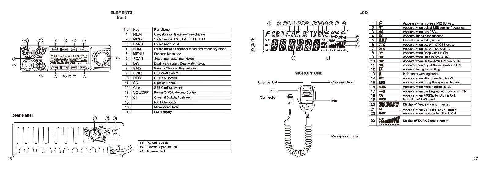
ELEMENTS ................................................................................................................... 26 - 27Front, rear, LCD, microphone
OPERATION ................................................................................................................. 28FUNCTION KEYS ......................................................................................................... 29 - 30MENU CHANNEL SETTINGS ...................................................................................... 31MENU PUBLIC DATA ................................................................................................... 32MENU BACKGROUND SETTINGS ............................................................................. 32 - 33SPECIFICATIONS ....................................................................................................... 34DECLARATION OF CONFORMITY ............................................................................ 51
With the TEAM HAM MobileCom 1011, you purchased a quality amateur mobile radio, designed to fulfill thehighest demands of radio communication.
The performance and the qualitiy of the HAM MobileCom 1011, which contains the newest technologies, willsatisfy you.
Please read this instruction manual carefully before operating the HAM MobileCom 1011 for the first time. Youwill learn about the proper setup, the different features and functions of your new mobile radio.
The HAM MobileCom 1011 is an amateur mobile radio and, therefore, can only be operated by a licenced amatuerradio operator. The amateur radio operator is responsible to comply with the license provisions.
PRECAUTIONS
Please follow the instructions to avoid fire, injuries and damage of the transceiver.
It is recommended, as a general guidline, not to exceed the suggested times for transmission (1 minute) and reception (4 minutes). These operations generate heat. Too much heat may cause damage.
Please do not disassemble or assemble the transceiver under any circumstances.
Please do not expose the transceiver to direct sunlight; do not place the transceiver near any heating devices, either.
Please do not put the transceiver in extremely dusty or moist places and do not place it on unstable, uneven surfaces.
If the transceiver emits smoke or strange odor, turn it off, disconnect it from the power source and immediately contact yourauthorized, local TEAM Electronic dealer.
CONTENTSUnpack the transceiver set carefully. We recommend that you identify the listed items before discarding the packing material.If any items are missing or have been damaged during shipment, please contact the dealer immediately.
HAM_MobileCom-1011_small-Dim:Layout 1 9/10/2014 12:39 PM Seite 20

22 23
OVERVIEW FUNCTIONS
1. Big LCD display; channel no. / frequency and various functions2. AM / FM / USB / LSB mode3. Frequency Tuning Step can be 10HZ, 100HZ, 100Khz,1MHz4. ± 1.5KHz Clarifier5. Menu functions PC programming software6. ECHO Function7. SQ, ASQ Function (FM and AM mode only)8. RF GAIN Adjustment9. RF PWR Adjustment
10. SCAN Function11. Programmable RB Function12. NB/ANL Function13. DW DUAL-WATCH Function14. BEEP Voice Prompt15. +10KHZ Function16. SWR, S/RF function17. TOT function18. HI-CUT Function19. EMG CALL, priority channels20. SWR PROTECTION21. Power Supply Voltage Protection22. Key-Lock Function23. 7 LCD colors 24. 10 memory banks with 40 channels each (programmable via software)25. PC programming with optional software
SETUP
microphone holder1. Mount the microphone holder with the two threading screws onto the desired location in the vehicle. 2. Plug in the 6-pin micrphone connector into the front jack (16), located on the left side of radio. Tighten the retaining
screw of the microphone plug.
antenna The antenna should be matched with the radio, otherwise a part of the transmit power will be reflected in the antennaand will not be radiated. This will reduce the range of operation. Since the antenna is one of the most important links inthe setup, the following criterias are very important.
General :
> The frequency range of the antenna has to cover the programmed frequencies on the radio.> The positon of the antenna should be as elevated and unobstructed as possible. > Ensure that the cable and the connector of the antenna are intact and that the plug is connected properly.> Ensure that the cable is not bend too much. > The length of the antenna rod and the range of operation are related. The longer the rod, the further the distance.
Upon antenna-mounting, the following has to be considered :
> The antenna should be placed in the middle of a vehicle part. > The antenna base should have good contact to a metal, conductive surface of the vehicle.
Base the decision about the position of the HAM MobileCom 1011 in your vehicle on the aspect of safety. No part of thesetup, i.e. radio, microphone, cable, etc., should restrict or obstruct the driver or passenger in any way.
U-bracket holder1. Mount the U-shaped bracket holder with the threading screws and the washers
at the desired location in the driver cabin. 2. Mount the radio onto the bracket holder with 2 adjusting screws and rubber
pads in the rear holes of the bracket holder. 3. Set the desired angle of the radio at the bracket holder and fix the angle with the remaining adjusting screws and rubber pads.
HAM_MobileCom-1011_small-Dim:Layout 1 9/10/2014 12:39 PM Seite 22

24 25
Beside the fixed mounting of antennas, which requires drilling of the body, antennas can also be set up via a magnetic mount.
> To avoid interferences with radio and TV reception, place the antenna as far away as possible from these sources of interferences.
> All connected cables should not exceed the maximum length of 3 meters.
For a good grounding of the antenna, we recommend one of these placements:
antenna connectionConnect the antenna connector of the cable with the PL-jack (20), located on the rear of theradio. Ensure a proper connection of the cable to the antenna base. Improper connectionscan cause damages to the radio and a reduction of the operational range may be the result.
The antenna setup has to be adjusted to the radio. Otherwise, a part of the transmissionpower is reflected at the antenna and is not radiated. A reduced range of operation could bethe consequence.
power supply connection The voltage has to be 13.8 V DC with negative grounding. Ensure that the positive and (+, red) and negative (-, black) pola-rity is correct, bevor you connect the radio. The connection of the radio to the power supply, has to be set up by an authori-zed technician.Connnect the power cable directly onto the batterie. Do not use a cigarette lighter adapter because this kind of connecti-vity might not provide enough currenct for a proper operation of the radio. Payspecial attention to the correct polarity,when connecting the cable onto the batterie.
CAUTION> Please ensure proper polarity > Please check the fuse before first use of the radio. Missed or defect fuses need to be re
placed before operation of the radio.
fuse replacement This radio requires a 15A/250V fuse. If the fuse blows, determine the cause, then correct the problem. After the problemis resolved, replace the fuse. If newly installed fuses continue to blow, disconnect the power cable and contact your aut-horized dealer or an authorized servicecenter.
1. Pull the two fuse cover in difference direction and open it.2. Replace the broke fuse with good one, and close the fuse holder.3. Be sure to use suggested fuse, or it might damage the radio.
INSTALL EXTERNAL SPEAKER
If you want to use an external speaker, please choose an 8 ohm speaker with 3.5 mm mono band plug.Position the external speaker in a safe location, where it cannot obstruct the driver or a passenger and plug the connectorinto the speaker jack (19), located on the rear of the radio.
HAM_MobileCom-1011_small-Dim:Layout 1 9/10/2014 12:39 PM Seite 24
26 27
ELEMENTSfront
LCD
MICROPHONE
HAM_MobileCom-1011_small-Dim:Layout 1 9/10/2014 12:39 PM Seite 26
28 29
OPERATION
On/Off1. To switch on the HAM MobileCom 1011, turn the volume control (13) clockwise, over the contact barrier. An acoustic
signal is emitted and the LCD lights up. 2. To switch off the radio, turn the volume control (13) counterclockwise over the contact barrier.
Volume Turning the volume control (13) will adjust the volume level. The LCD will then display the actual volume level (1-36).
TX Power For the adjustment of the tx power use the power control (9). The maximum tx power of the selected frequency band (AM /FM / SSB) is set by turning the power control clockwise all the way to the end.
RF Gain For the adjustment of the receiver sensitivity use the RF-Gain control (10). If received signals are distorted due to imme-diate proximity to the transmitter, the receiver sensitiviy can be reduced with the RF Gain function.
SQUELCHFor the adjustment of the squelch level use the squelch control (11). During adjustment, the symbol SQ and the actuallevel (1-36) are displayed.
SSB Clarifier For fine tuning of the transmitter and receiver frequencies for USB / LSB, use the SSB Clarifier control (12).
Channel Selection Use the rotary channel selector control (14) for channel selection.
Please note: for a manual entry of the frequency, push the rotary channel selector [PUSH] (14). The fourth digit starts blin-king. Set the value by turning the channel selector and push it to confirm the entry and to proceed to the next digit. Conti-nue repeating these steps until all entries have been made.
FUNCTION KEYS[MEM] MEMORY CHANNELS M1-M6:To enter or quit the memory channel mode, press the key【MEM】(1). The letter M (21) to the right of the frequency orthe memory channel number indicates the active status of the memory channel mode. In channel mode the display reads ME--M(1-6). In frequency mode, the frequency of the selected memory channel is dis-played. Use the key【FRQ】(4) to switch between the channel mode and the frequency mode. The selected frequencyband (A-I) is shown on the top of the LCD (13).
save a memory channel:To save a channel as a memory channel, exit memory channel mode first. Then, select the frequency and hold the key【MEM】until the memory channel mode is activated. The letter M and ME--M(1-6), with M(1-6) blinking, will appear. Now, select the memory channel number where the frequency should be savedand hold the key【MEM】until M(1-6) stops blinking.
[MODE]To switch between the operating modes FM-AM-USB-LSB, press the control【MODE】(2). The actual operating mode isshown in the upper left LCD (5).
[BAND]To switch between the frequency bands A-B-C-D-E-F-G-H-I-J, press the control【BAND】(3). The actual frequency band isshown in the upper left LCD (13).
[FRQ]Use the control【FRQ】(4) to switch between frequency and channel mode.
[MENU]All functions and settings of the HAM MobileCom 1011 are organized in three different menus. The menus channel settings (PD, HICUT, NB, ECHO, +10kHz, ROGER, BUSY, SCAN) and general settings (BEEP,INDIC, MIC, NOG, TOT, TSR, TDC, SCAN, FIN, COLOR, RESET) are activated with the control [MENU] (5).
HAM_MobileCom-1011_small-Dim:Layout 1 9/10/2014 12:39 PM Seite 28

30 31
To open the menu channel settings, press the key【MENU】(5) shortly. The symbol F (1) appears in the upper leftcorner of the LCD. Press the channel selector [PUSH] (14) to open the menu.
To open the menu general settings, press the key【MENU】(5) approximately 2 seconds.
Once the menu is activated, use the rotary channel selector (14) to select a function. To edit the setting for the selectedfunction, press the channel selector [PUSH] (14). Make your selection by turning the rotary channel selector and press it toconfirm your selection. To exit the menu press any key.
[SCAN] channel scanning 1. Start channel scanning by pressing the key【SCAN】(6). The symbol SC (4), located in the lower left corner, starts blinking.2. Change the direction of the scanning (Up / Down) by turning the rotary channel selector. 3. To stop the channel scanning press the key【SCAN】(6) again.
add to/delete from scan list In channel mode, only the channels of the scan list will be scanned. Channels that are added to the scan list can be re-cognized by the letter SC (4) in the lower, left corner. To add a channel to the scan list (or delete it), hold the key【SCAN】(6) for approximately 2 seconds. The scan list can also be edited via the menu channel settings.
[DW] Dual-Watch On/OffPressing shortly the key【DW】(7), will activate the dual watch function. Once activated, the symbol DW (10) appears.
Setup Dual Watch function 1. Select the first channel for the dual watch function. 2. Hold the key【DW】(10) for appr. 2 seconds until the symbol DW starts blinking. 3. Now, set the second channel for the dual watch function and press again the key【DW】(10) for confirmation.
[EMG]priority channels 9/19 and key lockpriority channel 9/19: The tri-state key【EMG】(15) switches from priority channel 9 to priority channel 19 and then back toregular mode. The priority channels 9 and 19 are indicated by the symbol EMG (15). key lock: To activate the key lock function, which deactivates all keys except for the PTT key, hold the key【EMG】(15)for approximately 2 seconds until the key symbol (17) appears.
MENU CHANNEL SETTINGS1. To open the menu channel settings, first, press the key【MENU】(5) shortly (the symbol F (1) will appear) and then,
press the channel selector【PUSH】(14). 2. Make your selection by turning the rotary channel selector (14). 3. Press the channel selector【PUSH】(14) to access the available settings. 4. Now, make your selection by turning the rotary channel selector (14) and confirm your selection by pressing the
channel selector【PUSH】(14). 5. To exit the menu, press the key【MENU】(5) or any other key.
No. Function LCD Symbol settings and description1 BUSY transmission blockage on occupied channels; ON/OFF2 REP direction of TX REP frequency shift
OFF : no shiftREP+ : shift to topREP- : shift to bottom
8 SCAN SC edit scan list; symbol SC (14) ADD / DEL
4 Public Data PD general settings; ON / OFF; activates / deactivates Menu Channel settings in active state, these functionsare not available: HICUT, NB, ECHO, 10KHZ and ROGER
5 HI-CUT HIC receiving tone type; ON / OFF 6 NB NB Noise Blanker; ON / OFF 7 ECHO ECHO Echo; ON / OFF
HAM_MobileCom-1011_small-Dim:Layout 1 9/10/2014 12:39 PM Seite 30
32 33
MENU PUBLIC DATA1. Press and hold the key【PUSH】(14) for appr. 2 seconds to open the menu. 2. Turn the rotary channel selector (14) to make your selection. 3. Push the key【PUSH】(14) to access the available settings for the function. 4. Turn the rotary channel selector (14) to make your selection. 5. Confirm the selection by pressing the key【PUSH】(14). 6. Press any key to exit the menu.
No. Function LCD Symbol settings and description1 Hi-cut HIC receipt tone type; ON / OFF
2 NB NB Noise Blanker; ON / OFF
3 Echo ECHO Echo; ON / OFF
4 10kHz 10k frequency shift +10 kHz; ON / OFF
5 Roger RB Roger Beep; 1-8, OFF
MENU BACKGROUND SETTINGS
1. Push and hold the key【MENU】(5) for appr. 2 seconds to open the menu. 2. Turn the rotary channel selector (14) to make your selection. 3. Push the key【PUSH】(14) to access the available settings for the function. 4. Turn the rotary channel selector (14) to make your selection. 5. Confirm the selection by pressing the key【PUSH】(14). 6. Press any key to exit the menu.
No. Function LCD Symbol settings and description1 BEEP BP beep tone; confirms any entry; ON / OFF2 INDIC OFF : transmit frequency during transmission
SWR : SWR during transmissionTOT : remaining TOT time during transmissionDC : indicates voltage during transmission
3 MIC microphone sensitivity; 1-364 NOG monitor sensitivity; 1-32, OFF5 TOT transmit time limiter; OFF, 30-600s in 30-seconds-steps6 TSR SWR protection, protects the radio if SWR is out of limit; ON / OFF
limit has to be programmed via software7 TDC Voltage protection, protects the radio if voltage is out of limits; ON / OFF
min. and max. limits, to be programmed via software8 SCM channel scan types
SQ : signalTI : time
9 FIN frequency fine-tuningOFFR : reception frequency fine-tuningT : transmission frequency fine-tuningRT : reception and transmission fine-tuning
10 COLOR LCD color; WHITE, BLUE, GREEN, YELLOW, RED, PURPLE, CYAN11 TX REP for repeater operation, tx frequency shift; range: 100Hz - 5MHz12 FR--CH settings: CHAN
FREQ13 ASQ automatich squelch
preset in the range 1-914 RESET reset to factory settings
OPT : all settings and functions ALL : all frequencies, settings and functions
HAM_MobileCom-1011_small-Dim:Layout 1 9/10/2014 12:39 PM Seite 32

34 35
SPECIFICATIONSGENERAL
Frequency Range 28.000-29.690 MHz (programmable)
Frequency Band A/B/C/D/E/F/G/H/I/J
Channel 40 channels (programmable) in each band
Frequency Control Phase-Locked-Loop Synthesizer
Frequency Step 100Hz / 1KHz / 10KHz / 100KHz / 1MHz
Frequency Tolerance 0.005%
Frequency Stability 0.001%
Temperature Range -20℃to +50℃
Microphone with push-to-talk /UP/DN and coiled cord
Input Voltage 13.8V
Dimensions (in mm) 245mm (W) x 157mm (D) x 48mm (H)
Weight 1.46kg
Antenna Connector UHF, SO239
TRANSMITTERPower Output AM: 12W / FM:30W / SSB: 60W (PEP)
Drain 12A (with modulation)
Modulation FM/AM/USB/LSB
Inter-modulation Distortion SSB: 3rd order, more than -25dB; 5th order, more than -35dB
SSB Carrier Suppression 55dB
Unwanted Sideband 50dB
Frequency Response AM/FM: 300 to 3000Hz / SSB: 450 to 2500Hz
Output Impedance 50 Ohms, unbalanced
CONTENIDOSMEDIDAS DE SEGURIDAD ............................................................................. 36
ELEMENTOS INCLUIDOS ............................................................................... 36
FUNICIONES Y CARACTERÍSTICAS .............................................................. 37
MONTAJE ......................................................................................................... 38 - 40Instalación de una antena, ................................................................. 38Conexión aérea, Micrófono, Fuente de alimentación.......................... 39Reemplazamiento del fusible, Instalación de un altavoz externo ....... 40
ELEMENTOS ................................................................................................... 41 - 42 Panel frontal, Display LCD .................................................................. 41Panel trasero, Micrófono ..................................................................... 42
OPERACIÓN .................................................................................................... 43 - 44TECLAS DE FUNCIONES ............................................................................... 4 4 - 46
MENÚ OPCIONES CANAL .............................................................................. 47
MENÚ CONFIGURACIÓN GENERAL ............................................................. 38
MENÚ AJUSTES DEL FONDO ........................................................................ 38 - 49
CARACTERÍSTICAS TÉCNICAS ........................................... .......................... 50
CE DECLARACIÓN DE CONFORMIDAD ....................................................... 51
Gracias por adquirir el TEAM HAM MobileCom 1011. TEAM electronic es conocido por la gran calidad de susaparatos de radiocomunicación.
Para entender todas las funciones, los posibles ajustes y para asegurar el funcionamiento adecuado de la radio,le recomendamos que lea este manual antes du utilizar la radio.
HAM_MobileCom-1011_small-Dim:Layout 1 9/10/2014 12:39 PM Seite 34
36 37
MEDIDAS DE SEGURIDAD
No transmite nunca sin antena; podría producirse un daño irreversible.
No exponga nunca la radio a los rayos del sol u otras fuentes de calor por mucho tiempo.
No exponga la radio a ningún líquido. La humedad podría causar corrosión de la PCB y sus componentes.
No coloque nunca la radio en zonas con altos niveles de polvo o suciedad.
Si la radio genera una calor inusual o emite un olor o humo, por favor, apáguela inmediatamente y desconectar el equipode la fuente de alimentación. Póngase en contacto con su distribuidor.
No abra el chasis de la radio. Abrirlo inadecuadamente podría causar daños que no cubriría la garantía del aparato.
Tiene todos los servicios y trabajos de reparación por un distribuidor cualificado.
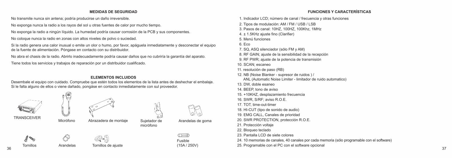
ELEMENTOS INCLUIDOS Desembale el equipo con cuidado. Compruebe que estén todos los elementos de la lista antes de deshechar el embalaje.Si le falta alguno de ellos o viene dañado, pongáse en contacto inmediatamente con sul proveedor.
TRANSCEIVERMicrófono Abrazadera de montaje
Tornillos Arandelas Tornillos de ajuste
FUNCIONES Y CARACTERÍSTICAS
1. Indicador LCD; número de canal / frecuencia y otras funciones
2. Tipos de modulación: AM / FM / USB / LSB 3. Pasos de canal: 10HZ, 100HZ, 100Khz, 1MHz4. ± 1.5KHz ajuste fino (Clarifier)5. Menú funciones 6. Eco 7. SQ, ASQ silenciador (sólo FM y AM) 8. RF GAIN; ajuste de la sensibilidad de la recepción9. RF PWR; ajuste de la potencia de transmisión
10. SCAN; escaneo11. resolución de paso (RB)12. NB (Noise Blanker - supresor de ruidos ) /
ANL (Automatic Noise Limiter - limitador de ruido automatico) 13. DW, doble esaneo14. BEEP, tono de aviso15. +10KHZ, desplazamiento frecuencia16. SWR, S/RF; aviso R.O.E. 17. TOT, time-out-timer18. HI-CUT (tipo de sonido de audio) 19. EMG CALL, Canales de prioridad20. SWR PROTECTION, protección R.O.E. 21. Protección voltaje22. Bloqueo teclado23. Pantalla LCD de siete colores 24. 10 memorias de canales, 40 canales por cada memoria (sólo programable con el software)25. Programable con el PC con el software opcional
Sujetador de micrófono
Arandelas de goma
Fusible(15A / 250V)
HAM_MobileCom-1011_small-Dim:Layout 1 9/10/2014 12:39 PM Seite 36
38 39
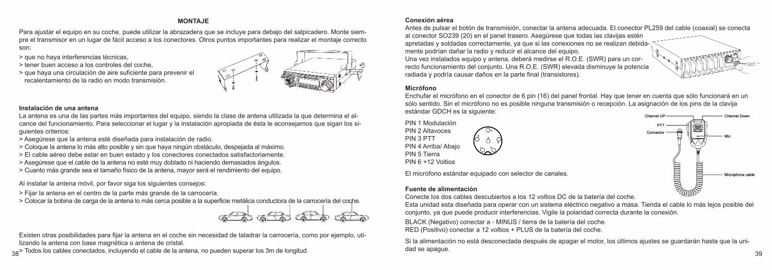
Para ajustar el equipo en su coche, puede utilizar la abrazadera que se incluye para debajo del salpicadero. Monte siem-pre el transmisor en un lugar de fácil acceso a los conectores. Otros puntos importantes para realizar el montaje correctoson:
> que no haya interferencias técnicas,> tener buen acceso a los controles del coche,> que haya una circulación de aire suficiente para prevenir el
recalentamiento de la radio en modo transmisión.
MONTAJE
Instalación de una antenaLa antena es una de las partes más importantes del equipo, siendo la clase de antena utilizada la que determina el al-cance del funcionamiento. Para seleccionar el lugar y la instalación apropiada de ésta le aconsejamos que sigan los si-guientes criterios:> Asegúrese que la antena esté diseñada para instalación de radio.> Coloque la antena lo más alto posible y sin que haya ningún obstáculo, despejada al máximo.> El cable aéreo debe estar en buen estado y los conectores conectados satisfactoriamente.> Asegúrese que el cable de la antena no esté muy doblado ni haciendo demasiados ángulos.> Cuanto más grande sea el tamaño físico de la antena, mayor será el rendimiento del equipo.
Al instalar la antena móvil, por favor siga los siguientes consejos:
> Fijar la antena en el centro de la parte más grande de la carrocería.> Colocar la bobina de carga de la antena lo más cerca posible a la superficie metálica conductora de la carrocería del coche.
Existen otras posibilidades para fijar la antena en el coche sin necesidad de taladrar la carrocería, como por ejemplo, uti-lizando la antena con base magnética o antena de cristal.> Todos los cables conectados, incluyendo el cable de la antena, no pueden superar los 3m de longitud.
Conexión aéreaAntes de pulsar el botón de transmisión, conectar la antena adecuada. El conector PL259 del cable (coaxial) se conectaal conector SO239 (20) en el panel trasero. Asegúrese que todas las clavijas esténapretadas y soldadas correctamente, ya que si las conexiones no se realizan debida-mente podrían dañar la radio y reducir el alcance del equipo.Una vez instalados equipo y antena, deberá medirse el R.O.E. (SWR) para un cor-recto funcionamiento del conjunto. Una R.O.E. (SWR) elevada disminuye la potenciaradiada y podría causar daños en la parte final (transistores).
MicrófonoEnchufar el micrófono en el conector de 6 pin (16) del panel frontal. Hay que tener en cuenta que sólo funcionará en unsólo sentido. Sin el micrófono no es posible ninguna transmisión o recepción. La asignación de los pins de la clavijaestándar GDCH es la siguiente:
PIN 1 ModulaciónPIN 2 AltavocesPIN 3 PTTPIN 4 Arriba/ AbajoPIN 5 TierraPIN 6 +12 Voltios
El micrófono estándar equipado con selector de canales.
Fuente de alimentaciónConecte los dos cables descubiertos a los 12 voltios DC de la batería del coche.Esta unidad esta diseñada para operar con un sistema eléctrico negativo a masa. Tienda el cable lo más lejos posible delconjunto, ya que puede producir interferencias. Vigile la polaridad correcta durante la conexión.
BLACK (Negativo) conectar a - MINUS / tierra de la batería del coche.RED (Positivo) conectar a 12 voltios + PLUS de la batería del coche.
Si la alimentación no está desconectada después de apagar el motor, los últimos ajustes se guardarán hasta que la uni-dad se apague.
HAM_MobileCom-1011_small-Dim:Layout 1 9/10/2014 12:39 PM Seite 38

40 41
Reemplazamiento del FusibleEste dispositivo requiere un fusible de 15 A / 250 V. Si el fusible está defectuoso, busca la razón y resuolva el problema. Si el nuevo fusible también se funde, disconecte laradio y póngase en contacto con su distribuidor.
1. Para abrir el fusible, tire de las dos cubiertas en direcciones opuestas. 2. Reemplace el fusible fundido y cierre el soporte.
Instalación de un altavoz externoSe puede conectar un altavoz externo (8 Ohm; enchufe 3,5 mm mono)
1. Posicionar el altavoz en un lugar seguro.2. Enchufe el conector en la toma del altavoz (19), situado en el panel posterior.
PANEL FRONTAL
DISPLAY LCD
HAM_MobileCom-1011_small-Dim:Layout 1 9/10/2014 12:39 PM Seite 40
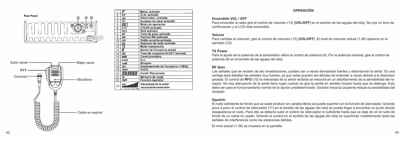
Micrófono
Cable en espiral
Conector
Subir canal Bajar canal
42 43
OPERACIÓN
Encendido VOL / OFFPara encender la radio gire el control de volumen (13) [VOL/OFF] en el sentido de las agujas del reloj. Se oye un tono deconfirmación y el LCD está encendido.
Volume Para cambiar el volumen, gire el control de volumen (13) [VOL/OFF]. El nivel de volumen actual (1-36) aparece en lapantalla LCD.
TX Power Para el ajuste de la potencia de la transmisión utilice el control de potencia (9). Por la potencia maximá, gire el control depotencia (9) en el sentido de las agujas del reloj.
RF Gain Las señales que se reciben de las inmediaciones, pueden ser a veces demasiado fuertes y distorsionan la señal. Es unaventaja para debilitar las señales muy fuertes, ya que estas pueden ser difíciles de entender a veces debido a la distorsiónpesada. El control de RFG (10) la intensidad de la señal recibida se reducirá en un debilitamiento de la sensibilidad del re-ceptor. No hay atenuación de la señal tiene lugar cuando se gira la perilla en sentido horario hasta que se detenga. Estodebe ser para el funcionamiento normal de la opción predeterminada. Girando hacia la izquierda reduce la sensibilidad delreceptor.
SquelchEl ruido estridente de fondo que se suele producir en canales libres se puede suprimir con la función de silenciador. Girandopoco a poco el control de silenciador (11) en el sentido de las agujas del reloj se puede llegar a encontrar un punto dondedesaparezca el ruido. Para ello se debería subir el control de silenciador lo suficiente hasta que se deje de oír el ruido defondo de un canal no usado. Girando el control en el sentido de las agujas del reloj se suprimirán notablemente tanto lasseñales de interferencia como las estaciones débiles.
El nivel actual (1-36) se muestra en la pantalla.
HAM_MobileCom-1011_small-Dim:Layout 1 9/10/2014 12:39 PM Seite 42

44 45
SSB Clarifier Para la sintonía fina del frecuencias transmisión y receptión USB / LSB, usa el control SSB Clarifier (12).
Selección de CanalTodos los canales se pueden seleccionar pulsando los botones de selector de canal en el micrófono, o bien girando el selectorrotatorio de canal (14) del panel frontal hasta encontrar el canal deseado.
Entrada manual: Es posible de entrar la frecuecia del canal con el selector rotatorio (14) [PUSH]. 1. Presione el selector (14), el último dígito parpadea. 2. Gire el selector rotatorio (14) y confirme su selección. 3. Repita los pasos 1. y 2. en cinco ocaciones por los otros dígitos.
TECLAS DE FUNCIONES
[MEM] Botones memoria de canal M1-M6:Para entrar o finir el modo de memoria de canal, pulsa el botón【MEM】(1). La lettra M (21) aparece a la derecha delfrecuencia o el número del canal. En modo número de canal, la pantalla muostra el símbolo ME--M(1-6). En modo frecuencia del canal, la pantalla muostra la frecuencia del memoria de canal seleccionado. Pulse el botón【FRQ】(4) para cambiar entre los modos número de canal y frecuencia de canal. La banda de frecuencia seleccionada (A-I) aparece en la parte superior de la pantalla (13).
guardar memoria de canal M1-M6:1. guardar memoria de canal:Deja el modo memoria de canal. Seleccione la frecuencia/canal deseado y mantenga pulsado el botón【MEM】(1) hastaque aparezca la letra M (21). En la pantalla el símbolo ME-M(1-6) parpadea. Seleccione el número del memoria de canal deseado y mantenga pulsado el botón【MEM】hasta que el símbolo M(1-6)deja de parpadear.
[MODE]Para cambiar entre los modos de operaciones FM-AM-USB-LSB, pulse el botón【MODE】(2). El modo seleccionadoaparece en la pantalla (5).
[BAND]Para cambiar entre las bandas de frecuencias A-B-C-D-E-F-G-H-I-J, pulse el botón【BAND】(3). La banda seleccionadaaparece en la pantalla (13). LCD (13).
[FRQ]Pulse el botón【FRQ】(4) para cambiar entre el modo frecuencia y el modo de canal.
[MENU]Todas las funciones y opciones del equipo están organizadas en tres menús.Los menús opciones de canal (PD, HICUT, NB, ECHO, +10kHz, ROGER, BUSY, SCAN) y opciones general (BEEP,INDIC, MIC, NOG, TOT, TSR, TDC, SCAN, FIN, COLOR, RESET) se activan con el botón [MENU] (5).
Para abrir el menú opciones de canal, pulse el botón【MENU】(5) brevemente (el símbolo F (1) aparece en la pantalla)y luego el botón【PUSH】(14).
Para abrir el menú opciones general, pulsa el botón【MENU】(5) durante aproximadamente 2 segundos.
1. Cuando se acitva el menú, use el selector rotatorio (14) para seleccionar un función.2. Para modificar las opciones del función seleccionada, pulse el selector rotatorio [PUSH]
(14) y gire el selector (14). 3. Para confirmar la seleccion pulsa el selector (14).
[SCAN]Escaneo de canal1. Pulse el botón【SCAN】(6) para comenzar el escaneo de canal. El símbolo SC (4) parpadea. 2. Cambie la dirección de la función escaneo con el selector rotatorio (14). 3. Pulse el botón【SCAN】(6) de nuevo para detener la función escaneo de canal.
HAM_MobileCom-1011_small-Dim:Layout 1 9/10/2014 12:39 PM Seite 44

46 47
Lista escaneo - guardar/eliminar En el modo número de canal, sólo los canales de la lista escaneo son escaneados. Cuando todos los canales de la listaescaneo el símbolo SC (4) apareca en la pantalla. Para guardar / eliminar un canal, pulse el botón【SCAN】(6) durante aproximadamente 2 segundos. También es posiblede guardar / eliminar un canal en el menú opciones canales.
[DW]Doble escucha Pulse brevemente el botón【DW】(7) para activar o desacitivar la función doble-escucha. En el estado activo la símboloDW (10) aparece en la pantalla.
1. Seleccione el primer canal.2. Mantega pulsado el botón【DW】(10) durante 2 segundos hasta que el símbolo DW parpadee. 3. Ahora, seleccione el segundo canal y pulsa el botón【DW】(10) de nuevo para confirmar la seleccion.
[EMG] canal prioritario 9/19 y función bloqueo
canal prioritario 9/19:El botón【EMG】(15) es una tecla de tres estados. Pulse el botón por primera vez para cambiar al canal 9. El símbolo EMG (15) aparace. Pulse el botón por segunda vez para cambiar al canal 19. El símbolo EMG (15) aparace.Pulse el botón por tercera vez para desactivar la función prioritario.
función bloqueo:La función bloqueo desactiva todo las teclas funcionales excepto el botón PTT. Para activar la función, mantega pulsado el botón【EMG】(15) durante 2 segundos hasta que el símbolo de la llave par-padee.
MENÚ OPCIONES CANAL 1. Para abrir el menú opciones canal, pulsa el botón 【MENU】(5) brevemente (el símbolo F (1) aparece) y pulsa el
selector rotativo 【PUSH】(14). 2. Seleccione la functión con el selector rotatorio (14). 3. Pulse el selector rotativo 【PUSH】(14) para acceder a las opciones de la función. 4. Ahora, gire el selector rotativo (14) para seleccionar la opción desea y pulsa el selector rotativo【PUSH】(14) para
confirmar la selección. 5. Para dejar el menú, pulsa el botón 【MENU】(5) o una otra tecla.
N° Función Símbolo LCD Descripción ________ 1 Public Data PD Configuración general; (ON/OFF); en estado activo
funciones están disponibles: ECHO, +10kHz, ROGER, BUSY y SCAN
2 HI-CUT HIC Tono de recepción; (ON/OFF)
3 NB NB Supresor de ruidos (Noise Blanker); (ON/OFF)
4 ECHO ECHO Eco (Echo); (ON/OFF)
5 10KHz 10K Desplazamiento de frecuencia +10 kHz; (ON/OFF)
6 ROGER Roger Beep; 1-8, (OFF)
7 BUSY Transmisión bloqueo de canales ocupados; (ON/OFF)
8 SCAN SC Editar la lista canales escaneo; el símbolo SC (14) indica el estado activo; guardar/eliminar (ADD/DEL)
HAM_MobileCom-1011_small-Dim:Layout 1 9/10/2014 12:39 PM Seite 46

48 49
MENÚ CONFIGURACIÓN GENERAL (PUBLIC DATA)
1. Mantenga pulsado el botón【PUSH】(14) durante 2 segundos hasta que se abra el menú. 2. Gire el selector rotativo (14) y seleccione. 3. Pulse el botón 【PUSH】(14) para acceder a las opciones y gire el selector rotativo (14).4. Pulse el botón 【PUSH】(14) para confirmar la selección. 5. Pulse cualquier tecla para salir el menú.
N° Función Símbolo LCD Descripción 1 Hi-cut HIC Tono de recepción; (ON/OFF)
2 NB NB Supresor de ruidos (Noise Blanker); (ON/OFF)
3 ECHO ECHO Eco (Echo); (ON/OFF)
4 10KHz 10K Desplazamiento de frecuencia +10 kHz; (ON/OFF)
5 ROGER Roger Beep; 1-8, (OFF)
MENÚ DE AJUSTES 1. Mantenga pulsado el botón【PUSH】(14) durante 2 segundos hasta que se abra el menú. 2. Gire el selector rotativo (14) y seleccione. 3. Pulse el botón 【PUSH】(14) para acceder a las opciones y gire el selector rotativo (14).4. Pulse el botón 【PUSH】(14) para confirmar la selección. 5. Pulse cualquier tecla para salir el menú.
N° Función Símbolo LCD Descripción 1 BEEP BP Tono de aviso; confirma cualquier entrada; (ON/OFF)
2 INDIC OFF : Indica la frecuencia transmisión durante transmisiónSWR : Indica R.O.E. durante transmisiónTOT : Indica TOT tiempo restante durante transmisiónDC : Indica voltaje durante transmisión
3 MIC Sensibilidad micrófono; 1-36
4 NOG Monitor sensibilidad; 1-32, OFF
5 TOT Limitador tiempo transmisión; (OFF), 30-600s
6 TSR R.O.E. protección, protege la radio si la ROE está fuera de límites; (ON/OFF) programable con el software
7 TDC Protection voltage, protege al radio si la ROE está fuera de límites; (ON/OFF)Límites min. y max. se programan por software
8 SCM Tipos de esaneo de canal: SQ (Señal) / TI (Tiempo)
9 FIN Frecuencia sintonía fina OFF : AagadoR : Recepción frecuencia sintonía finaT : Transmisión frecuencia sintonía finaRT : Recepción y transmisión sintonía fina
10 COLOR Color LCD: Blanco (WHITE), azul (BLUE), verde (GREEN), amarillo (YELLOW), rojo (RED), púrpura (PURPLE), cian (CYAN)
11 TX REP para la operación de repetidor, desplazamiento tx frecuencia; 100Hz - 5MHz
12 FR--CH seleccione: CHAN (canal) / FREQ (frecuencia)
13 ASQ silenciador automático, 1-9
14 RESET Volver a la configuración de fábrica OPT: Todos los ajustes y funciones / ALL: Todos los frecuencias, ajustes y funciones
HAM_MobileCom-1011_small-Dim:Layout 1 9/10/2014 12:39 PM Seite 48

50 51
CARACTERÍSTICAS TÉCNICASGENERAL
Gama de frecuencias 28.000-29.695MHz (programmable)
Bandas de frecuencias A/B/C/D/E/F/G/H/I/J
Canales 40 canales (programmable) en cada banda
Frecuencia control Phase-Locked-Loop Synthesizer
Pasos de frecuencia 100Hz / 1KHz / 10KHz / 100KHz / 1MHz
Tolerancia de frecuencia 0.005%
Estabilidad de frecuencia 0.001%
Gama de temperaturas -20℃to +50℃
Micrófono con PTT, UP/DN y cable en espiral
Voltaje de entrada 13.8V
Dimensiones (mm) 245mm x 158mm x 48mm
Peso 1,46kg
Conector antena SO239
TRANSMISORPotencia RF Portadora AM: 12W / FM: 30W / SSB: 60W (PEP)
Consumo 12A (con modulación)
Modulación FM/AM/USB/LSB
Inter-Modulación Distorsión SSB: 3° orden, más que -25dB; 5° orden, más que -35dB
SSB Supresión portadora 55dB
Banda Lateral no deseada 50dB
Tolerancia de frecuencia AM/FM: 300 - 3000Hz; SSB: 450 - 2500Hz
Impedancia salida 50 Ohms, desequilibrado
Dec
lara
tion
Of C
onfo
rmity
/ K
onfo
rmitä
tser
klär
ung
We
here
by d
ecla
re th
at th
e pr
oduc
t: / W
ir er
klär
en h
ierm
it, d
ass
das
Pro
dukt
:
VHF-
UH
F am
ateu
r mob
ile tr
ansc
eive
r / V
HF-
UH
F A
mat
eurf
unk
Mob
ilger
ät
(28,
000
– 29
,695
MH
z / T
X P
ower
max
. 12
W (A
M);
30 W
(FM
); 60
W (S
SB
))
TEA
M H
AM
Mob
ileC
om 1
011
satis
fies
all t
he t
echn
ical
reg
ulat
ions
app
licab
le
to
the
prod
uct
with
in
the
scop
e of
C
ounc
il D
irect
ives
, E
urop
ean
stan
dard
s an
d na
tiona
l fre
quen
cy a
pplic
atio
ns:
alle
te
chni
sche
n A
nfor
deru
ngen
im
G
eltu
ngsb
erei
ch d
er E
U-R
icht
linie
n, e
urop
äisc
her
Nor
men
un
d na
tiona
ler
Freq
uenz
anw
endu
ngen
ei
nhäl
t:
73/2
3/EE
C, 8
9/33
6/EE
C, 9
3/68
/EEC
and
R&
TTE
1999
/5/E
C
EN
301
489
-1 V
1.9.
EN
301
489
-15
V1.2
.1
EN 3
01 7
83-1
V1.
2.1
EN 3
01 7
83-2
V1.
2.1
EN 6
0950
-1:2
006+
A11
:200
9+A
1:20
10+A
12:2
011
A
ll es
sent
ial r
adio
tes
t su
ites
have
bee
n ca
rrie
d ou
t. A
lle
für
das
Pro
dukt
vo
rges
chrie
bene
n Fu
nkm
essu
ngen
wur
den
durc
hgef
ührt.
The
HA
M M
obile
Com
101
1 is
an
amat
eur
radi
o (H
AM
rad
io)
and
can
only
be
oper
ated
with
a
valid
am
ateu
r rad
io li
cenc
e.
The
amat
eur
radi
o op
erat
er i
s re
spon
sibl
e fo
r th
e ab
iden
ce o
f the
reg
ulat
ions
.
Das
H
AM
M
obile
Com
10
11
ist
ein
Am
ateu
rfunk
gerä
t un
d da
rf nu
r vo
n liz
enzi
erte
n A
mat
eurfu
nker
n be
trieb
en w
erde
n. D
ie E
inha
ltung
de
r Li
zenz
best
imm
unge
n lie
gt
in
der
Eig
enve
rant
wor
tlich
keit
des
Am
ateu
rfunk
ers.
The
unit
can
be d
istri
bute
d an
d op
erat
ed in
the
follo
win
g co
untri
es:
Aus
tria
(AT)
, B
elgi
um
(BE
), B
ulga
ria
(BG
), S
witz
erla
nd
(CH
), C
ypru
s (C
Y)
, C
zech
R
epub
lic (
CZ)
, G
erm
any
(DE
), D
enm
ark
(DK
), S
pain
(E
S),
Finl
and
(FI),
Fra
nce
(FR
), G
reat
B
ritai
n (G
B),
Gre
ece
(GR
), H
unga
ry
(HU
), Ire
land
(IE
), Ita
ly (I
T), L
uxem
bour
g (L
U),
Lat
via
(LV
), P
olan
d (P
L),
Net
herla
nds
(NL)
, N
orw
ay
(NO
), R
oman
ia (
RO
), S
wed
en (
SE
), S
love
nia
(SI),
Slo
vac
Rep
ublic
(SK
)
Die
ses
Ger
ät is
t in
den
folg
ende
n Lä
nder
n fü
r den
V
ertri
eb u
nd d
en G
ebra
uch
zuge
lass
en :
Ö
ster
reic
h (A
T), B
elgi
um (B
E),
Bul
garie
n (B
G),
S
chw
eiz
(CH
), Zy
pern
(CY)
, Ts
chec
hien
(CZ)
,
Bun
desr
epub
lik D
euts
chla
nd (D
E),
Dän
emar
k (D
K),
S
pani
en (E
S),
Finn
land
(FI),
Fra
nkre
ich
(FR
),
Gro
ßbrit
anni
en (G
B),
Grie
chen
land
(GR
), U
ngar
n (H
U),
Irl
and
(IE),
Italie
n (IT
), Lu
xem
burg
(LU
), L
ettla
nd (L
V),
P
olen
(PL)
, Nie
derla
nde
(NL)
, Nor
weg
en (N
O),
R
umän
ien
(RO
), S
chw
eden
(SE
), S
low
enie
n (S
I),
Slo
wak
ei (S
K)
M
anuf
actu
rer:
/ H
erst
elle
r:
TEA
M E
lect
roni
c G
es.m
.b.h
. K
leßh
eim
er A
llee
47
A-5
020
Salz
burg
Th
is
decl
arat
ion
is
issu
ed
unde
r th
e so
le
resp
onsi
bilit
y of
the
man
ufac
ture
r. D
iese
E
rklä
rung
w
ird
unte
r un
sere
r al
lein
igen
V
eran
twor
tung
abg
egeb
en.
Pla
ce a
nd d
ate
of is
sue:
/ O
rt un
d D
atum
: Sa
lzbu
rg, 1
4.04
.201
4
(S
igna
ture
) Fr
ank
Mik
e D
ietz
TE
AM
Ele
ctro
nic
Ges
.m.b
.H.
HAM_MobileCom-1011_small-Dim:Layout 1 9/10/2014 12:39 PM Seite 50

V1 07/2014
HAM MobileCom 1011
für den Verkauf und Betrieb in:for sale and use in:
para la venta y operación en:
Austria (AT), Belgium (BE), Bulgaria (BG), Cyprus (CY), Czech Republic (CZ), Denmark (DK), Estonia(EE), Finland (FI), France (FR), Germany (DE), United Kingdom (UK), Greece (GR), Hungary (HU), Iceland
(IS) Ireland (IE), Italy (IT), Latvia (LV), Lithuania (LT), Luxembourg (LU), Malta (MT), Netherlands (NL), Norway (NO), Poland (PL), Portugal (PT), Romania (RO, Switzerland (CH), Slovak Republic (SK), Slovenia
(SL), Spain (ES), Sweden (SE)
TEAM Electronic GmbHBolongarostrasse 88
D-65929 Frankfurt am MainGERMANY
Tel. ++49 - 69 - 300 9 500Fax ++49 - 69 - 314382
eMail [email protected] Page www.team-electronic.de
Nachdruck oder Vervielfältigung – auch auszugsweise – nur mit Genehmigung von TEAM Electronic GmbH. technische Änderungen vorbehalten
HAM_MobileCom-1011_small-Dim:Layout 1 9/10/2014 12:39 PM Seite 52


