96
Functional Bonding and Shielding of PROFIBUS and PROFINET Guideline for PROFIBUS and PROFINET Version 1.0 – Date March 2018 Order No.: 8.102
Functional Bonding and Shielding of PROFIBUS and PROFINET
Guideline
for PROFIBUS and PROFINET
Version 1.0 – Date March 2018
Order No.: 8.102

Functional Bonding and Shielding V 1.0
© Copyright PNO 2018 - All Rights Reserved Page 2 of 96
File name: Earthing-Shielding_8102_V10_Mar18 Prepared by PI Working Group PG3 “Installation Guide PB&PN” in Committee CB “PROFINET”. The attention of adopters is directed to the possibility that compliance with or adoption of PI (PROFIBUS International)
specifications may require use of an invention covered by patent rights. PI shall not be responsible for identifying patents for which a license may be required by any PI specification, or for conducting legal inquiries into the legal validity or scope of those patents that are brought to its attention. PI specifications are prospective and advisory only. Prospective users are responsible for protecting themselves against liability for infringement of patents.
NOTICE:
The information contained in this document is subject to change without notice. The material in this document details a PI specification in accordance with the license and notices set forth on this page. This document does not repre-sent a commitment to implement any portion of this specification in any company's products.
WHILE THE INFORMATION IN THIS PUBLICATION IS BELIEVED TO BE ACCURATE, PI MAKES NO WARRANTY OF ANY KIND, EXPRESS OR IMPLIED, WITH REGARD TO THIS MATERIAL INCLUDING, BUT NOT LIMITED TO ANY WARRANTY OF TITLE OR OWNERSHIP, IMPLIED WARRANTY OF MERCHANTABILITY OR WARRANTY OF FITNESS FOR PARTICULAR PURPOSE OR USE.
In no event shall PI be liable for errors contained herein or for indirect, incidental, special, consequential, reliance or cover damages, including loss of profits, revenue, data or use, incurred by any user or any third party. Compliance with this specification does not absolve manufacturers of PROFIBUS or PROFINET equipment, from the requirements of safety and regulatory agencies (TÜV, BIA, UL, CSA, FCC, IEC, etc.).
PROFIBUS® and PROFINET® logos are registered trade marks. The use is restricted to members of PROFIBUS&PROFINEWT International. More detailed terms for the use can be found on the web page http://www.profibus.com/download/presentations-logos/.
Publisher: PROFIBUS Nutzerorganisation e.V. Haid-und-Neu-Str. 7 76131 Karlsruhe Germany Phone: +49 721 / 96 58 590 Fax: +49 721 / 96 58 589 E-mail: [email protected] Web site: www.profibus.com © No part of this publication may be reproduced or utilized in any form or by any means, electronic or mechanical, including photocopying and microfilm, without permission in writing from the publisher.
Functional Bonding and Shielding V1.0
© Copyright PNO 2018 - All Rights Reserved Page 3 of 96
Disclaimer of Liability
PROFIBUS Nutzerorganisation e.V. (PROFIBUS user organization, hereinafter in this
disclaimer referred to as “PNO”) has taken utmost care in the preparation of this docu-
ment and compiled all information to the best of its knowledge. This document is never-
theless based on present knowledge, is of an informative character and is provided on
the basis of liability exclusion. Therefore, this document may be subject to change, en-
hancement or correction in the future without any expressive reference. PNO expres-
sively refuses all types of contractual or legal liability for this document, including the
warranty for defects and the assurance of certain usage properties. Under no circum-
stances shall PNO accept liability for any loss or damage caused by or resulting from
any defect, error or omission in this document.
This document has no normative character. It may be useful in certain operating envi-
ronments, in certain technical constellations or when used in certain countries to deviate
from the given recommendations. In this case, installers and operators of the plant
should weigh up the advantages and disadvantages of the recommendations made in
the specific application and, if deemed appropriate, decide on the implementation of a
different solution if necessary.
Management Summary
This document deals with the shielding of PROFIBUS/PROFINET networks and with
equipotential bonding in the corresponding plants in non-hazardous areas. The docu-
ment describes an optimized structure for process automation systems intended to re-
duce the effects of electromagnetic interference (EMI) and disturbances by using equi-
potential bonding systems. In a tiered approach, the readers are first made familiar with
the technical basics of electromagnetic compatibility (EMC), equipotential bonding and
shielding. In chapter 4, six recommendations for action are developed by using a plant
example.
Functional Bonding and Shielding V1.0
© Copyright PNO 2018 - All Rights Reserved Page 4 of 96
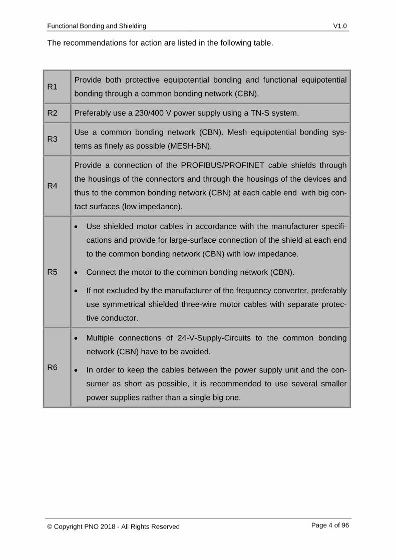
The recommendations for action are listed in the following table.
R1 Provide both protective equipotential bonding and functional equipotential
bonding through a common bonding network (CBN).
R2 Preferably use a 230/400 V power supply using a TN-S system.
R3 Use a common bonding network (CBN). Mesh equipotential bonding sys-
tems as finely as possible (MESH-BN).
R4
Provide a connection of the PROFIBUS/PROFINET cable shields through
the housings of the connectors and through the housings of the devices and
thus to the common bonding network (CBN) at each cable end with big con-
tact surfaces (low impedance).
R5
• Use shielded motor cables in accordance with the manufacturer specifi-
cations and provide for large-surface connection of the shield at each end
to the common bonding network (CBN) with low impedance.
• Connect the motor to the common bonding network (CBN).
• If not excluded by the manufacturer of the frequency converter, preferably
use symmetrical shielded three-wire motor cables with separate protec-
tive conductor.
R6
• Multiple connections of 24-V-Supply-Circuits to the common bonding
network (CBN) have to be avoided.
• In order to keep the cables between the power supply unit and the con-
sumer as short as possible, it is recommended to use several smaller
power supplies rather than a single big one.
Functional Bonding and Shielding V1.0
© Copyright PNO 2018 - All Rights Reserved Page 5 of 96
Content Disclaimer of Liability ....................................................................................................... 3
Management Summary ................................................................................................... 3
1 Introduction ............................................................................................................. 10
1.1 Introduction to the subject/problem ..................................................................... 10
1.2 Aim of this document .......................................................................................... 11
2 EMI fundamentals .................................................................................................. 12
2.1 Couplings ............................................................................................................ 13
2.1.1 Conductive coupling ........................................................................................ 14
2.1.2 Capacitive coupling ......................................................................................... 17
2.1.3 Inductive coupling............................................................................................ 18
2.1.4 Radiated coupling............................................................................................ 18
2.2 Electrostatic discharge ........................................................................................ 19
2.3 Typical sources of disturbance in automation systems ....................................... 20
3 Fundamentals of equipotential bonding and shielding ............................................ 21
3.1 Cable shielding ................................................................................................... 21
3.1.1 Passive shielding............................................................................................. 21
3.1.2 Active shielding ............................................................................................... 22
3.2 Equipotential bonding ......................................................................................... 24
3.2.1 Protective earth conductor (PE) ...................................................................... 24
3.2.2 Protective equipotential bonding ..................................................................... 24
3.2.3 Functional equipotential bonding (FE) ............................................................. 26
4 Recommendations for the design of PROFIBUS and PROFINET networks
with little disturbance ............................................................................................... 27
4.1 Combination of protective and functional equipotential bonding systems ........... 30
4.1.1 Problem description ......................................................................................... 30
4.1.2 Solutions from standards and specialist literature ........................................... 31
4.1.3 Recommendations for PROFIBUS and PROFINET ........................................ 31
4.2 Implementation of 230/400V mains supply ......................................................... 32
4.2.1 Problem descriptions ....................................................................................... 34
4.2.1.1 Mains supply network as TN-C system .................................................... 34
4.2.1.2 Mains supply network as TN-C-S system ................................................ 38
4.2.1.3 Mains supply network as TN-S system .................................................... 41
4.2.2 Descriptions in the relevant standards and specialist literature ....................... 45

Functional Bonding and Shielding V1.0
© Copyright PNO 2018 - All Rights Reserved Page 6 of 96
4.2.3 Recommendations for PROFIBUS and PROFINET ........................................ 46
4.3 Equipotential bonding system ............................................................................. 48
4.3.1 Problem description ......................................................................................... 49
4.3.2 Solutions from standards and technical literature ............................................ 55
4.3.3 Recommendations for PROFIBUS and PROFINET ........................................ 58
4.4 Connection of PROFIBUS/PROFINET cable shields .......................................... 67
4.4.1 Problem description with solutions from standards and technical literature .... 67
4.4.2 Recommendations for PROFIBUS and PROFINET ........................................ 70
4.5 Motor lines .......................................................................................................... 71
4.5.1 Problem description ......................................................................................... 71
4.5.1.1 Capacitive coupling in motor lines ............................................................ 72
4.5.1.2 Inductive coupling in motor lines .............................................................. 73
4.5.2 Solutions from standards and specialist literature ........................................... 75
4.5.3 Recommendations for PROFIBUS and PROFINET ........................................ 78
4.6 Connecting the negative pole of 24 V power supply to the CBN ......................... 79
4.6.1 Problem description ......................................................................................... 81
4.6.1.1 Connection of 24 V power supply circuits to CBN, scenario 1 ................. 82
4.6.1.2 Connection of 24 V power supply circuits to CBN, scenario 2 ................. 83
4.6.1.3 Connection of 24 V power supply circuits to the CBN, scenario 3............ 84
4.6.2 Solutions from standards and technical literature ............................................ 84
4.6.3 Recommendations for PROFIBUS and PROFINET ........................................ 85
5 Summary of the recommendations for the design of PROFIBUS and
PROFINET networks with little disturbance ............................................................ 87
6 Suggestions for possible acceptance tests ............................................................. 89
7 List of reference documents ................................................................................... 92
Functional Bonding and Shielding V1.0
© Copyright PNO 2018 - All Rights Reserved Page 7 of 96
List of figures
Figure 1: Evaluation of the assignments of the Field Service Excellence WG from 2009
to 20014 [GÖH2015] ..................................................................................................... 10
Figure 2: EMC interfaces of a device according to [RUD2011] ...................................... 12
Figure 3: Coupling lines ................................................................................................. 13
Figure 4: Conductive coupling in equipotential bonding system 1 ................................. 14
Figure 5: Conductive coupling in equipotential bonding system 2 ................................. 15
Figure 6: Conductive coupling in equipotential bonding system 3 ................................. 15
Figure 7: Conductive coupling in equipotential bonding system 4 ................................. 16
Figure 8: Capacitive coupling ........................................................................................ 17
Figure 9: Inductive coupling ........................................................................................... 18
Figure 10: Repetition of capacitive coupling .................................................................. 22
Figure 11: Active shielding with one-sided connection to the common bonding
network (CBN) .............................................................................................. 22
Figure 12: Induction in the cable shield ......................................................................... 23
Figure 13: Plant example from the process industry ...................................................... 28
Figure 14: Plant example from the manufacturing industry ........................................... 29
Figure 15: Network systems .......................................................................................... 32
Figure 16: TN-C-S system as network system .............................................................. 33
Figure 17: TN-C system................................................................................................. 34
Figure 18: TN-C system with load ................................................................................. 35
Figure 19: TN-C system with load and current flow ....................................................... 35
Figure 20: TN-C system with several connections to the equipotential
bonding system............................................................................................. 36
Figure 21: TN-C system with multiple earthing, load and current flow ........................... 37
Figure 22: TN-C-S system ............................................................................................. 38
Figure 23: Current flow in a TN-C-S system .................................................................. 39
Functional Bonding and Shielding V1.0
© Copyright PNO 2018 - All Rights Reserved Page 8 of 96
Figure 24: Current flow in a TN-C-S system with multiple earthing ............................... 39
Figure 25: Current flow in a TN-C-S system with targeted multiple earthing ................. 40
Figure 26: TN-S system ................................................................................................. 41
Figure 27: TN-S system with load .................................................................................. 42
Figure 28: TN-S system with load and current flow ....................................................... 42
Figure 29: TN-S system with two PEN bridges .............................................................. 43
Figure 30: TN-S system with two PEN bridges, load and current flow ........................... 43
Figure 31: Ideal TN-S system ........................................................................................ 46
Figure 32: Star-type equipotential bonding .................................................................... 48
Figure 33: Tree-type equipotential bonding ................................................................... 49
Figure 34: Equipotential bonding system in star topology with PROFIBUS lines ........... 50
Figure 35: Equipotential bonding system in star topology with PROFIBUS lines 2 ........ 51
Figure 36: Equipotential bonding system in star topology with PROFIBUS lines 3 ........ 51
Figure 37: Meshes in an equipotential bonding system with star topology .................... 52
Figure 38: PROFIBUS lines and equipotential bonding lines......................................... 53
Figure 39: Meshes with PROFIBUS lines and equipotential bonding lines .................... 54
Figure 40: Equipotential bonding systems referring to [DIN-EN 50310] ........................ 55
Figure 41: Meshed equipotential bonding system ......................................................... 56
Figure 42: Improved equipotential bonding systems referring to [DIN-EN 50310] ......... 57
Figure 43: Meshed equipotential bonding ...................................................................... 58
Figure 44: Ring lines in meshed equipotential bonding system ..................................... 59
Figure 45: Stubs of the meshed equipotential bonding system ..................................... 60
Figure 46: Connection blocks (WPAK clamps) (picture from Weidmüller, manf.) .......... 61
Figure 47: Stubs from ring line to devices (Picture Weidmüller)] ................................... 61
Figure 48: Meshed equipotential bonding via the foundation earth electrode ................ 62
Figure 49: Earthing points [DEH2016] ........................................................................... 63
Figure 50: Mesh formed by a cable shield in a meshed equipotential bonding system . 64
Functional Bonding and Shielding V1.0
© Copyright PNO 2018 - All Rights Reserved Page 9 of 96
Figure 51: Many small meshes in a meshed equipotential bonding system .................. 65
Figure 52: Example of electrostatic discharge ............................................................... 66
Figure 53: Connection of the cable shield to CBN close to a PROFINET device .......... 68
Figure 54: Multiple connection of the cable shield of a PROFIBUS line with the CBN .. 69
Figure 55: Additional connection of the cable shield (Product Indu Sol,
Photo Niemann) ............................................................................................ 69
Figure 56: Shielded motor line ....................................................................................... 71
Figure 57: Capacitive coupling in shielded motor lines .................................................. 72
Figure 58: Magnetic field lines in a motor line ................................................................ 73
Figure 59: Inductive coupling between L1 and L2 ......................................................... 73
Figure 60: Inductive coupling in a motor line ................................................................. 74
Figure 61 Typical installation of a frequency converter from [DAN2015]. ...................... 76
Figure 62: Drive with low voltage power supply from [ABB2005]................................... 77
Figure 63: Symmetrical motor lines as recommended by [SIE2014] ............................. 78
Figure 64: 24 V power supply in a manufacturing plant ................................................. 79
Figure 65: Simplified representation of a 24 V power supply circuit .............................. 80
Figure 66: Multiple earthing in a 24 V power supply circuit ............................................ 81
Figure 67: Connection 24 V power supply circuits to CBN, scenario 1 .......................... 82
Figure 68: Connection of 24 V power supply circuits to CBN, scenario 2 ...................... 83
Figure 69: Connecton of 24 V power supply circuits to CBN, scenario 3 ....................... 84
Figure 70: Optimal earthing of 24 V power supply circuits ............................................. 86
List of tables
Table 1: Frequency spectrum of potential sources of disturbance from [SCH2008] ...... 20
Table 2: Suggestions for possible acceptance tests ..................................................... 90
Functional Bonding and Shielding V 1.0
© Copyright PNO 2018 - All Rights Reserved Page 10 of 96
1 Introduction
This document deals with functional bonding and shielding of PROFIBUS/PROFINET
networks and with equipotential bonding in plants in non-hazardous areas. The aim is to
provide users and designers with a standardized procedure in order to achieve a dis-
turbance-free structure for automation systems. In addition to the procedures described
in this document, the applicable standards and guidelines for electrical safety must be
observed. The illustrations and symbols used in this document may differ from those in
the relevant standards and guidelines.
1.1 Introduction to the subject/problem
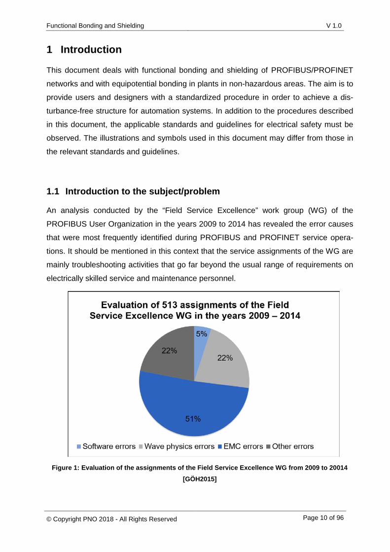
An analysis conducted by the “Field Service Excellence” work group (WG) of the
PROFIBUS User Organization in the years 2009 to 2014 has revealed the error causes
that were most frequently identified during PROFIBUS and PROFINET service opera-
tions. It should be mentioned in this context that the service assignments of the WG are
mainly troubleshooting activities that go far beyond the usual range of requirements on
electrically skilled service and maintenance personnel.
Figure 1: Evaluation of the assignments of the Field Service Excellence WG from 2009 to 20014
[GÖH2015]

Functional Bonding and Shielding V1.0
© Copyright PNO 2018 - All Rights Reserved Page 11 of 96
Figure 1 clearly shows that EMC errors resulting from electromagnetic incompatibility
have caused more than half of the service assignments of the companies joining the
Field Service Excellence work group. These EMC errors are mainly problems that mani-
fest themselves through impermissibly high shield currents, inductances without inter-
ference suppression and loads of the equipotential bonding systems.
1.2 Aim of this document
The aim of this document is to provide a basis for the functional bonding and shielding
of PROFIBUS and PROFINET bus systems. The focus is not on the design of
PROFIBUS/PROFINET devices, but on their correct connection and on the cabling of
plants in order to prevent field-based disturbances and disturbances through the equi-
potential bonding system.
In a tiered approach, the readers are first made familiar with the technical basics of
electromagnetic compatibility. Then the document imparts the fundamentals of function-
al bonding and shielding in process automation systems. In the next step, six recom-
mendations for actions allowing to implement PROFIBUS and PROFINET networks with
only little disturbance are given. A list of acceptance criteria completes this document.
Functional Bonding and Shielding V1.0
© Copyright PNO 2018 - All Rights Reserved Page 12 of 96
2 EMI fundamentals
Electromagnetic interference (EMI) is a phenomenon where devices are affected by
electric and magnetic fields. All electrical devices generate magnetic and electric fields,
which may disturb the function of other devices. For example, EMI causes potential
problems and data loss in communication lines. The counterpart of EMI is electromag-
netic compatibility (EMC). A device's EMC must ensure that no field-conducted or line-
conducted influences may disturb the device.
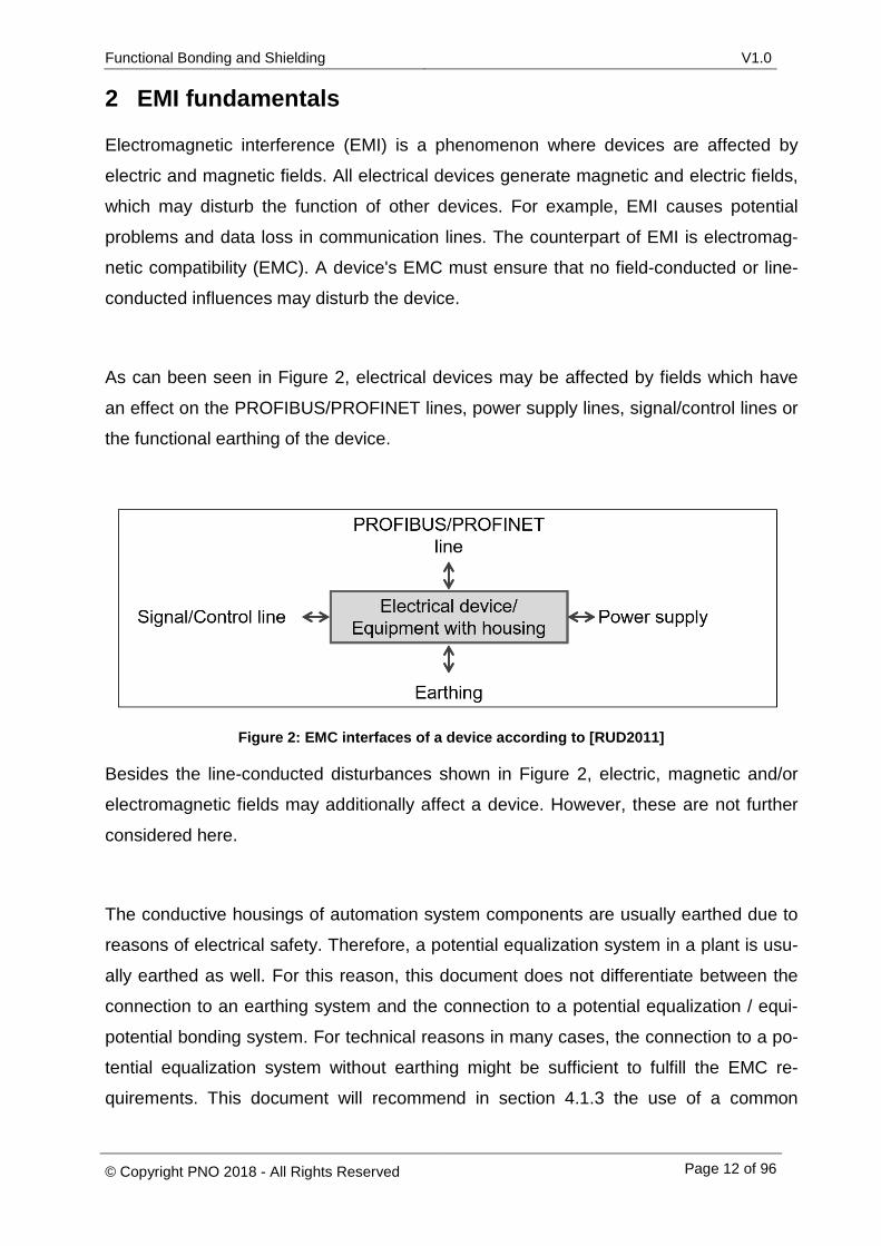
As can been seen in Figure 2, electrical devices may be affected by fields which have
an effect on the PROFIBUS/PROFINET lines, power supply lines, signal/control lines or
the functional earthing of the device.
Figure 2: EMC interfaces of a device according to [RUD2011]
Besides the line-conducted disturbances shown in Figure 2, electric, magnetic and/or
electromagnetic fields may additionally affect a device. However, these are not further
considered here.
The conductive housings of automation system components are usually earthed due to
reasons of electrical safety. Therefore, a potential equalization system in a plant is usu-
ally earthed as well. For this reason, this document does not differentiate between the
connection to an earthing system and the connection to a potential equalization / equi-
potential bonding system. For technical reasons in many cases, the connection to a po-
tential equalization system without earthing might be sufficient to fulfill the EMC re-
quirements. This document will recommend in section 4.1.3 the use of a common
Functional Bonding and Shielding V1.0
© Copyright PNO 2018 - All Rights Reserved Page 13 of 96
bonding network (CBN) that serves the purpose of potential equalization, functional
earthing and protective earthing. The expression CBN will be used in this document.
2.1 Couplings
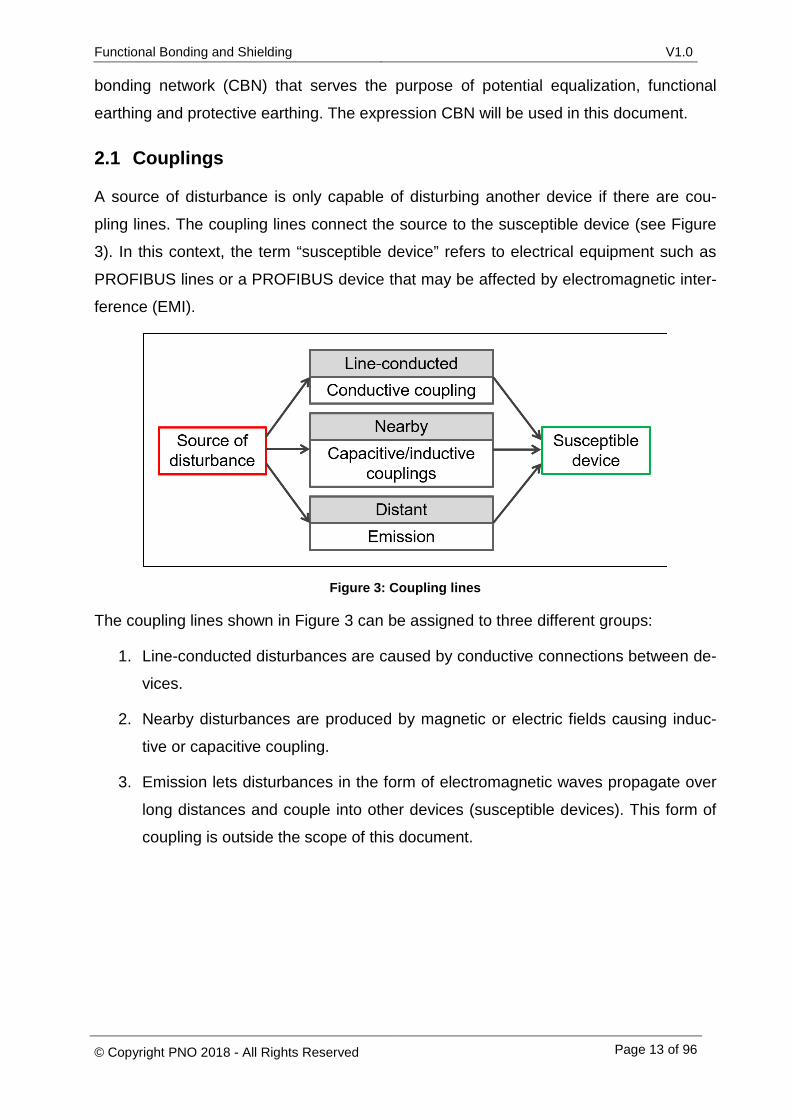
A source of disturbance is only capable of disturbing another device if there are cou-
pling lines. The coupling lines connect the source to the susceptible device (see Figure
3). In this context, the term “susceptible device” refers to electrical equipment such as
PROFIBUS lines or a PROFIBUS device that may be affected by electromagnetic inter-
ference (EMI).
Figure 3: Coupling lines
The coupling lines shown in Figure 3 can be assigned to three different groups:
1. Line-conducted disturbances are caused by conductive connections between de-
vices.
2. Nearby disturbances are produced by magnetic or electric fields causing induc-
tive or capacitive coupling.
3. Emission lets disturbances in the form of electromagnetic waves propagate over
long distances and couple into other devices (susceptible devices). This form of
coupling is outside the scope of this document.
Functional Bonding and Shielding V1.0
© Copyright PNO 2018 - All Rights Reserved Page 14 of 96
2.1.1 Conductive coupling
Conductive coupling requires an electrically conductive connection between two current
circuits. This connection is also called coupling impedance. The common current flow of
the two current circuits causes a voltage drop across the coupling impedance. This volt-
age drop produces a potential shift at both consumers (loads). Due to this potential shift,
the voltage of the consumers/loads may fall below or exceed their rated voltage.
[SCH2008]
Conductive coupling is hence a frequent cause of the emergence of potential differ-
ences in equipotential bonding systems. The drawings below illustrate the causes of
potential differences in equipotential bonding systems.
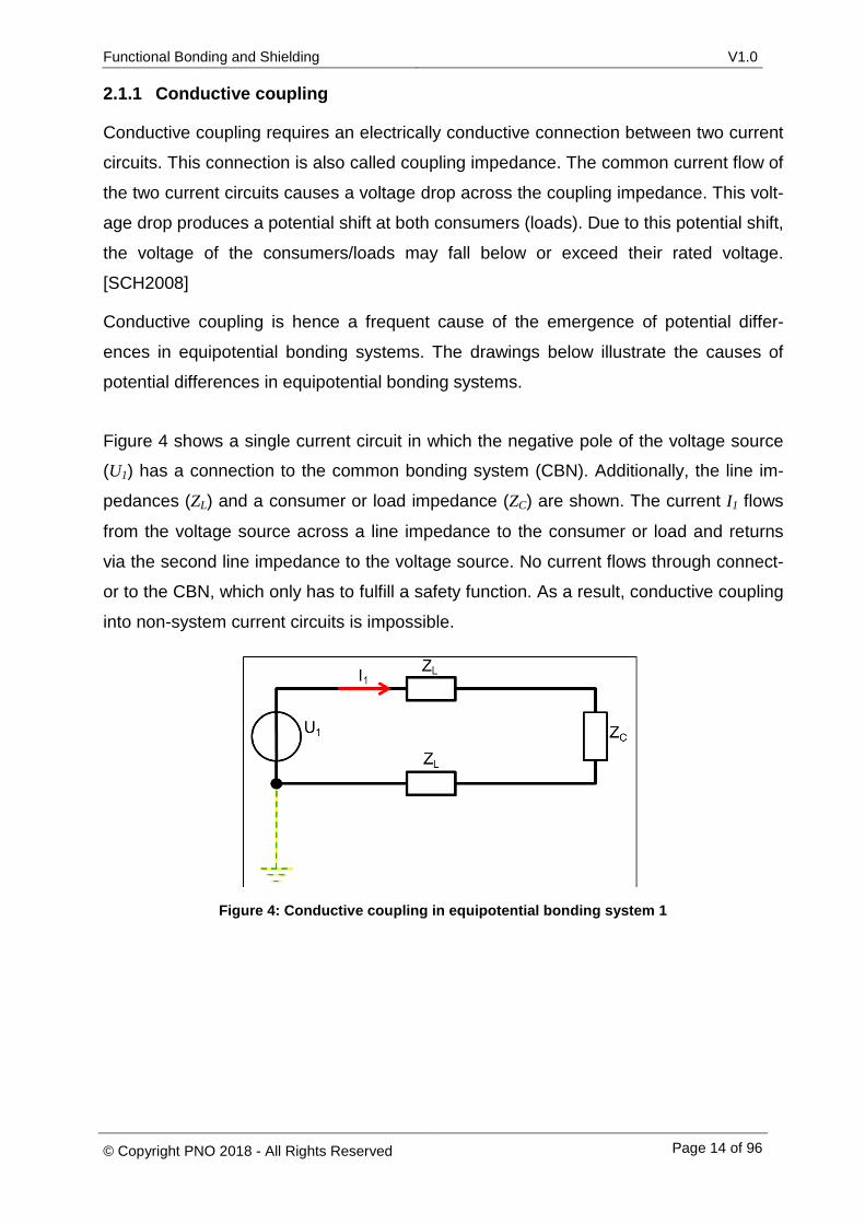
Figure 4 shows a single current circuit in which the negative pole of the voltage source (U1) has a connection to the common bonding system (CBN). Additionally, the line im-
pedances (ZL) and a consumer or load impedance (ZC) are shown. The current I1 flows
from the voltage source across a line impedance to the consumer or load and returns
via the second line impedance to the voltage source. No current flows through connect-
or to the CBN, which only has to fulfill a safety function. As a result, conductive coupling
into non-system current circuits is impossible.
Figure 4: Conductive coupling in equipotential bonding system 1
Functional Bonding and Shielding V1.0
© Copyright PNO 2018 - All Rights Reserved Page 15 of 96
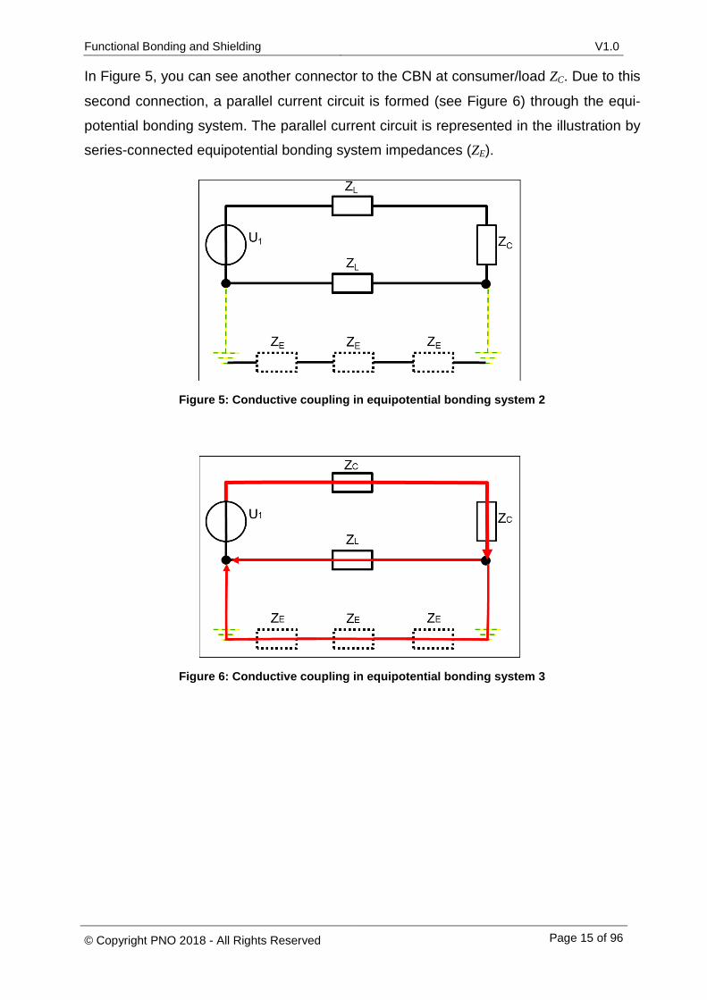
In Figure 5, you can see another connector to the CBN at consumer/load ZC. Due to this
second connection, a parallel current circuit is formed (see Figure 6) through the equi-
potential bonding system. The parallel current circuit is represented in the illustration by
series-connected equipotential bonding system impedances (ZE).
Figure 5: Conductive coupling in equipotential bonding system 2
Figure 6: Conductive coupling in equipotential bonding system 3
Functional Bonding and Shielding V1.0
© Copyright PNO 2018 - All Rights Reserved Page 16 of 96
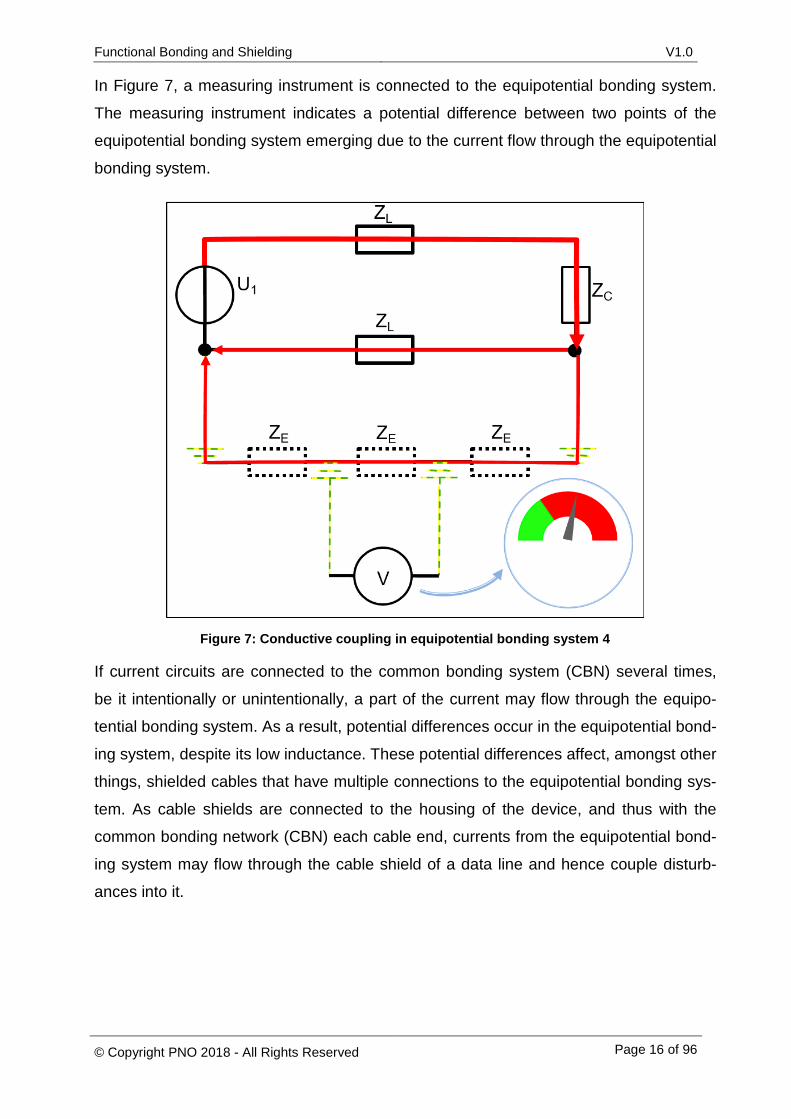
In Figure 7, a measuring instrument is connected to the equipotential bonding system.
The measuring instrument indicates a potential difference between two points of the
equipotential bonding system emerging due to the current flow through the equipotential
bonding system.
Figure 7: Conductive coupling in equipotential bonding system 4
If current circuits are connected to the common bonding system (CBN) several times,
be it intentionally or unintentionally, a part of the current may flow through the equipo-
tential bonding system. As a result, potential differences occur in the equipotential bond-
ing system, despite its low inductance. These potential differences affect, amongst other
things, shielded cables that have multiple connections to the equipotential bonding sys-
tem. As cable shields are connected to the housing of the device, and thus with the
common bonding network (CBN) each cable end, currents from the equipotential bond-
ing system may flow through the cable shield of a data line and hence couple disturb-
ances into it.
Functional Bonding and Shielding V1.0
© Copyright PNO 2018 - All Rights Reserved Page 17 of 96
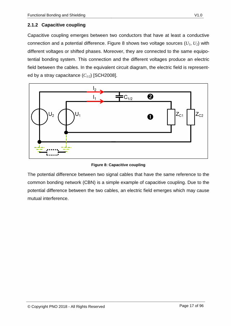
2.1.2 Capacitive coupling
Capacitive coupling emerges between two conductors that have at least a conductive connection and a potential difference. Figure 8 shows two voltage sources (U1, U2) with
different voltages or shifted phases. Moreover, they are connected to the same equipo-
tential bonding system. This connection and the different voltages produce an electric
field between the cables. In the equivalent circuit diagram, the electric field is represent-ed by a stray capacitance (C1/2) [SCH2008].
Figure 8: Capacitive coupling
The potential difference between two signal cables that have the same reference to the
common bonding network (CBN) is a simple example of capacitive coupling. Due to the
potential difference between the two cables, an electric field emerges which may cause
mutual interference.
Functional Bonding and Shielding V1.0
© Copyright PNO 2018 - All Rights Reserved Page 18 of 96
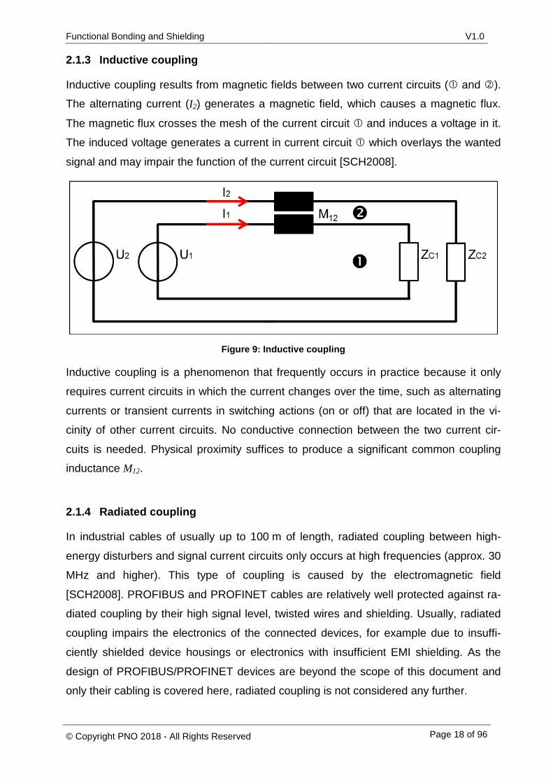
2.1.3 Inductive coupling
Inductive coupling results from magnetic fields between two current circuits ( and ). The alternating current (I2) generates a magnetic field, which causes a magnetic flux.
The magnetic flux crosses the mesh of the current circuit and induces a voltage in it.
The induced voltage generates a current in current circuit which overlays the wanted
signal and may impair the function of the current circuit [SCH2008].
Figure 9: Inductive coupling
Inductive coupling is a phenomenon that frequently occurs in practice because it only
requires current circuits in which the current changes over the time, such as alternating
currents or transient currents in switching actions (on or off) that are located in the vi-
cinity of other current circuits. No conductive connection between the two current cir-
cuits is needed. Physical proximity suffices to produce a significant common coupling inductance M12.
2.1.4 Radiated coupling
In industrial cables of usually up to 100 m of length, radiated coupling between high-
energy disturbers and signal current circuits only occurs at high frequencies (approx. 30
MHz and higher). This type of coupling is caused by the electromagnetic field
[SCH2008]. PROFIBUS and PROFINET cables are relatively well protected against ra-
diated coupling by their high signal level, twisted wires and shielding. Usually, radiated
coupling impairs the electronics of the connected devices, for example due to insuffi-
ciently shielded device housings or electronics with insufficient EMI shielding. As the
design of PROFIBUS/PROFINET devices are beyond the scope of this document and
only their cabling is covered here, radiated coupling is not considered any further.

Functional Bonding and Shielding V1.0
© Copyright PNO 2018 - All Rights Reserved Page 19 of 96
2.2 Electrostatic discharge
Electrostatic charges emerge from major potential differences caused by friction or sep-
aration of different materials. Friction of different materials leads to the transfer of elec-
trons (charge separation) between the two materials. Due to the electron transfer, one
material collects a positive charge and one material a negative charge. Typical exam-
ples of electrostatic charges emerging in an industrial environment are charges pro-
duced by plastic containers on a conveyor. Filling bulk material or liquids from one ves-
sel into another is also likely to produce electrostatic charges. The electrostatic charges
are discharged as soon as there is a conductive connection between two materials with
a sufficiently high potential difference or a spark is produced because the dielectric
strength of the air gap is exceeded. The resulting high current flow may disturb sensors
and the related data communication [KLE2016].
Functional Bonding and Shielding V1.0
© Copyright PNO 2018 - All Rights Reserved Page 20 of 96
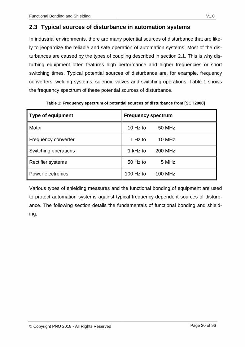
2.3 Typical sources of disturbance in automation systems
In industrial environments, there are many potential sources of disturbance that are like-
ly to jeopardize the reliable and safe operation of automation systems. Most of the dis-
turbances are caused by the types of coupling described in section 2.1. This is why dis-
turbing equipment often features high performance and higher frequencies or short
switching times. Typical potential sources of disturbance are, for example, frequency
converters, welding systems, solenoid valves and switching operations. Table 1 shows
the frequency spectrum of these potential sources of disturbance.
Table 1: Frequency spectrum of potential sources of disturbance from [SCH2008]
Type of equipment Frequency spectrum
Motor 10 Hz to 50 MHz
Frequency converter 1 Hz to 10 MHz
Switching operations 1 kHz to 200 MHz
Rectifier systems 50 Hz to 5 MHz
Power electronics 100 Hz to 100 MHz
Various types of shielding measures and the functional bonding of equipment are used
to protect automation systems against typical frequency-dependent sources of disturb-
ance. The following section details the fundamentals of functional bonding and shield-
ing.
Functional Bonding and Shielding V1.0
© Copyright PNO 2018 - All Rights Reserved Page 21 of 96
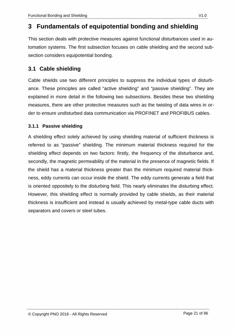
3 Fundamentals of equipotential bonding and shielding
This section deals with protective measures against functional disturbances used in au-
tomation systems. The first subsection focuses on cable shielding and the second sub-
section considers equipotential bonding.
3.1 Cable shielding
Cable shields use two different principles to suppress the individual types of disturb-
ance. These principles are called “active shielding” and “passive shielding”. They are
explained in more detail in the following two subsections. Besides these two shielding
measures, there are other protective measures such as the twisting of data wires in or-
der to ensure undisturbed data communication via PROFINET and PROFIBUS cables.
3.1.1 Passive shielding
A shielding effect solely achieved by using shielding material of sufficient thickness is
referred to as “passive” shielding. The minimum material thickness required for the
shielding effect depends on two factors: firstly, the frequency of the disturbance and,
secondly, the magnetic permeability of the material in the presence of magnetic fields. If
the shield has a material thickness greater than the minimum required material thick-
ness, eddy currents can occur inside the shield. The eddy currents generate a field that
is oriented oppositely to the disturbing field. This nearly eliminates the disturbing effect.
However, this shielding effect is normally provided by cable shields, as their material
thickness is insufficient and instead is usually achieved by metal-type cable ducts with
separators and covers or steel tubes.
Functional Bonding and Shielding V1.0
© Copyright PNO 2018 - All Rights Reserved Page 22 of 96
3.1.2 Active shielding
Due to the low material thickness of cable shields, the active shielding effect is used.
However, for active shielding to work, it is necessary to connect the cable shield to the
common bonding network (CBN) at several points in order to establish a current circuit
[WOL2008].
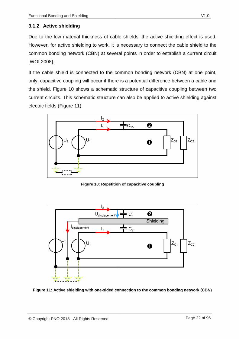
It the cable shield is connected to the common bonding network (CBN) at one point,
only, capacitive coupling will occur if there is a potential difference between a cable and
the shield. Figure 10 shows a schematic structure of capacitive coupling between two
current circuits. This schematic structure can also be applied to active shielding against
electric fields (Figure 11).
Figure 10: Repetition of capacitive coupling
Figure 11: Active shielding with one-sided connection to the common bonding network (CBN)
Functional Bonding and Shielding V1.0
© Copyright PNO 2018 - All Rights Reserved Page 23 of 96
Due to one-sided connection of the cable shield (shown in gray color in Figure 11) to the
common bonding network, the two stray capacitances C1 and C2 are produced between
the current circuits ( and ) and the cable shield. These stray capacitances emerge
because the cable shield has a 0 V potential resulting from its connection to the com-
mon bonding network (CBN). Coupling disturbances from current circuit into current
circuit is hence prevented, because the displacement currents (Idisplacement) coupled
into the circuit can directly return to the voltage source U2.
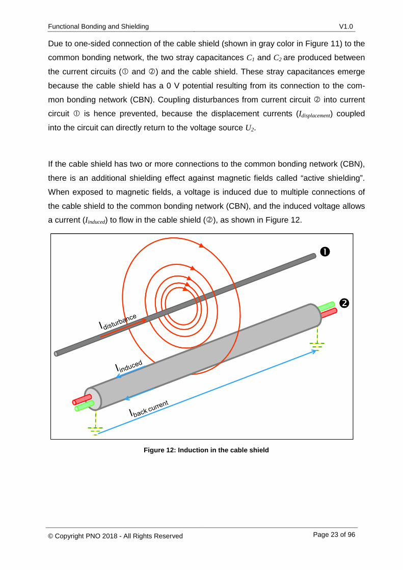
If the cable shield has two or more connections to the common bonding network (CBN),
there is an additional shielding effect against magnetic fields called “active shielding”.
When exposed to magnetic fields, a voltage is induced due to multiple connections of
the cable shield to the common bonding network (CBN), and the induced voltage allows a current (Iinduced) to flow in the cable shield (), as shown in Figure 12.
Figure 12: Induction in the cable shield
Functional Bonding and Shielding V1.0
© Copyright PNO 2018 - All Rights Reserved Page 24 of 96
The induced current flow produces a counter-induction with a 180° phase shift to the
initial induction of the magnetic field. Inside the cable, the magnetic field of the disturb-
ance and the magnetic field of counter-induction overlay each other. This overlay pro-
duces an area that is nearly free from any fields in the middle of the cable [WOL2008].
For this reason, cable shields should be connected to the common bonding network
(CBN) at least at both ends in order to achieve a sufficient shielding effect against mag-
netic fields and alternating electromagnetic fields.
3.2 Equipotential bonding
Earthing points can be found everywhere in a plant or on plant equipment. A distinction
is made between protective earthing (PE) and functional equipotential bonding. Protec-
tive earthing is intended to ensure the safety of humans and to prevent hazardous touch
voltages on housings and other conductive parts. Functional equipotential bonding, in
contrast, serves the equipotential bonding of devices that is not safety relevant.
3.2.1 Protective earth conductor (PE)
The protective earth conductor ensures protection of electrical active devices with the
protective measure “protective earthing” in the event of a fault. It facilitates the protec-
tion of persons against electrical shock by indirect contact.
Indirect contact is caused by an electrically conductive, usually metallic, object of elec-
trical active devices, which may build up an electrical voltage to earth in the event of a
fault. Such a fault scenario could be a 230 V cable, which has accidentally come loose
and come in to contact with a metal part of the device. Therefore, every electrical device
with an operating voltage above 50 VDC or 120 VAC must have a PE-terminal for the
protective earth conductor.
3.2.2 Protective equipotential bonding
A different setting applies for electrically passive, but touchable, conductive parts of the
plant, e.g. a handrail, a protective fence or a roller conveyor. Here no PE terminal is
present. However, it is recommended to connect those parts of the plant to the protec-
tive equipotential bonding system. If a handrail is connected to the protective equipoten-
tial bonding system, then - in the case of an error (phase connected to the handrail due
to failure of basic and additional insulation) - a fault current can trigger a protective de-
vice like a fuse or an RCD and switch off the circuit.
Functional Bonding and Shielding V1.0
© Copyright PNO 2018 - All Rights Reserved Page 25 of 96
As the handrail is connected to the protective equipotential bonding conductor, a fault
current of sufficient intensity is produced and triggers a safety device (fuse, fault current
circuit breaker) to disconnect the current circuit from mains. If, however, the handrail
were not connected to the protective equipotential bonding conductor, a voltage of 230
V would be present between the handrail and earth, presenting a danger to the life of
humans and (farm) animals that might come into contact with it. It is therefore recom-
mended to connect all passive, electrically conductive objects such as pipes, protective
fences, ladders, handrails, metal cable ducts or other structural components to the pro-
tective equipotential bonding in order to prevent impermissible touch voltages.
In this document, the connection of electrical equipment to a protective conductor or
protective equipotential bonding is marked by the following symbol:
Functional Bonding and Shielding V1.0
© Copyright PNO 2018 - All Rights Reserved Page 26 of 96
3.2.3 Functional equipotential bonding (FE)
“The purpose of functional equipotential bonding is the reduction of:
- the effects of an insulation fault that may affect operation of a machine; - the effects of electrical disturbances on sensitive electrical equipment that may
affect operation of a machine.” [DIN-EN 60204-1]
This means that functional equipotential bonding does not serve the safety of humans
and (farm) animals, but the functional reliability of a plant. Among the objects that are
usually connected to the functional equipotential bonding are, for example, motor
shields, data cable shields and functional bonding conductors of sensitive component
parts.
In this document, the connection of electrical equipment to a functional equipotential
bonding is marked by the following symbol:

Functional Bonding and Shielding V1.0
© Copyright PNO 2018 - All Rights Reserved Page 27 of 96
4 Recommendations for the design of PROFIBUS and PROFINET networks with little disturbance
These recommendations provide instructions on how to design systems with only little
disturbance. The individual recommendations deal with the following:
- Combination of protective and functional equipotential bonding systems to form a
common network
- Implementation of 230/400 V power supply differentiation between the individual
types of earthing for network systems (TN-S, TN-C, TN-C-S, TT and IT)
- Minimum distances between power cables and PROFIBUS/PROFINET cables
- Setup of the equipotential bonding system
- Connection of PROFIBUS/PROFINET cable shields
- Peculiarities of motor cables
- Connection of the negative pole in a 24 V power supply circuit to the common
bonding network (CBN)
The following subsections provide general explanations and problem descriptions for all
seven topics on the basis of standards and specialist literature. Additionally, a recom-
mendation for the functional bonding and shielding of PROFIBUS/PROFINET networks
is derived from the standards. The recommendations are applicable for both the manu-
facturing industry and the process industry. The only exception is the application in haz-
ardous areas where this subject is not covered by these recommendations, as addition-
al regulations are valid and must be observed for the functional bonding and shielding of
cables in hazardous areas. For bus lines that either leave the building envelope or are
laid outdoors the applicable lightning protection directives must also be observed in ad-
dition to this document. It is recommended to preferably use fiber optic cables as bus
lines that leave buildings or are supplied from different main distributors.
Functional Bonding and Shielding V1.0
© Copyright PNO 2018 - All Rights Reserved Page 28 of 96
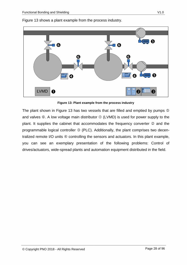
Figure 13 shows a plant example from the process industry.
Figure 13: Plant example from the process industry
The plant shown in Figure 13 has two vessels that are filled and emptied by pumps
and valves . A low voltage main distributor (LVMD) is used for power supply to the
plant. It supplies the cabinet that accommodates the frequency converter and the
programmable logical controller (PLC). Additionally, the plant comprises two decen-
tralized remote I/O units controlling the sensors and actuators. In this plant example,
you can see an exemplary presentation of the following problems: Control of
drives/actuators, wide-spread plants and automation equipment distributed in the field.
Functional Bonding and Shielding V1.0
© Copyright PNO 2018 - All Rights Reserved Page 29 of 96
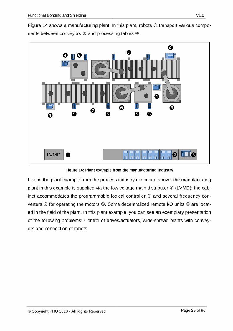
Figure 14 shows a manufacturing plant. In this plant, robots transport various compo-
nents between conveyors and processing tables .
Figure 14: Plant example from the manufacturing industry
Like in the plant example from the process industry described above, the manufacturing
plant in this example is supplied via the low voltage main distributor (LVMD); the cab-
inet accommodates the programmable logical controller and several frequency con-
verters for operating the motors . Some decentralized remote I/O units are locat-
ed in the field of the plant. In this plant example, you can see an exemplary presentation
of the following problems: Control of drives/actuators, wide-spread plants with convey-
ors and connection of robots.
Functional Bonding and Shielding V1.0
© Copyright PNO 2018 - All Rights Reserved Page 30 of 96
4.1 Combination of protective and functional equipotential bonding systems
In the manufacturing industry and in the process industry both separate and common
protective and functional equipotential bonding systems are used. Separating the two
systems is reasonable under the assumption that in this case no currents flowing in the
protective equipotential bonding system can couple into the functional equipotential
bonding system, causing disturbances. Protective equipotential bonding serves the
safety of humans and (farm) animals. Functional equipotential bonding serves to ensure
full plant functionality, for example by eliminating disturbances caused by electromag-
netic fields. Both equipotential bonding systems are laid out in a star or tree topology
distributed over the entire plant area, and they are interconnected at a just one point.
Usually, the central protective earth connector (Main Earth Terminal) of the plant is used
as the connection point for the protective and the functional equipotential bonding sys-
tems.
4.1.1 Problem description
Nowadays, having completely separated functional equipotential bonding and protective
equipotential bonding systems in a plant is no longer practical as there are always sev-
eral points in a plant where unwanted connections are likely to occur.
For example, the usage of PROFIBUS and PROFINET may result in a connection be-
tween the functional and the protective equipotential bonding system. In order to ensure
full functionality of PROFIBUS/PROFINET lines, you have to connect each line end to
the functional equipotential bonding system (see section 3.1.2).
To achieve this, the cable shield has to be connected to a large contact surface on a
PROFIBUS/PROFINET connector housing, a separate equipotential bonding bar or a
suitable shield connector at the device. This measure already satisfies the requirement
to connect the functional and the protective equipotential bonding systems to each oth-
er.
Functional Bonding and Shielding V1.0
© Copyright PNO 2018 - All Rights Reserved Page 31 of 96
4.1.2 Solutions from standards and specialist literature
No standard requires a strict separation of the functional and protective equipotential
bonding systems. In the standard [DIN-EN 60204-1] you will find an explanation on how
to achieve functional equipotential bonding by means of a connection to the protective
equipotential bonding system. If, however, the protective equipotential bonding system
is heavily loaded by currents, providing a separate functional equipotential bonding sys-
tem may become necessary.
Hence, when using a common equipotential bonding system it must be ensured that the
currents flowing through it are as low as possible.
Additionally, the standard [IEC 60364-5-54] requires that common protective and func-
tional equipotential bonding conductors always have to meet the requirements on pro-
tective conductors. With this, the minimum cross-sectional areas, line impedances, min-
imum ampacity and protection against self-loosening of equipotential bonding
conductors are clearly defined.
4.1.3 Recommendations for PROFIBUS and PROFINET
As already stated, a strict separation of functional and protective equipotential bonding
systems is not feasible in practice, as unintended connections between the two bonding
systems frequently occur. Moreover, attempts to separate the two systems can incur
high costs. Common equipotential bonding is therefore recommended. A common equi-
potential bonding system of this kind is referred to as Common Bonding Network (CBN).
It combines both the protective functions required for triggering circuit breakers in case
of a fault and the functional equipotential bonding functions for avoiding electromagnetic
interference.
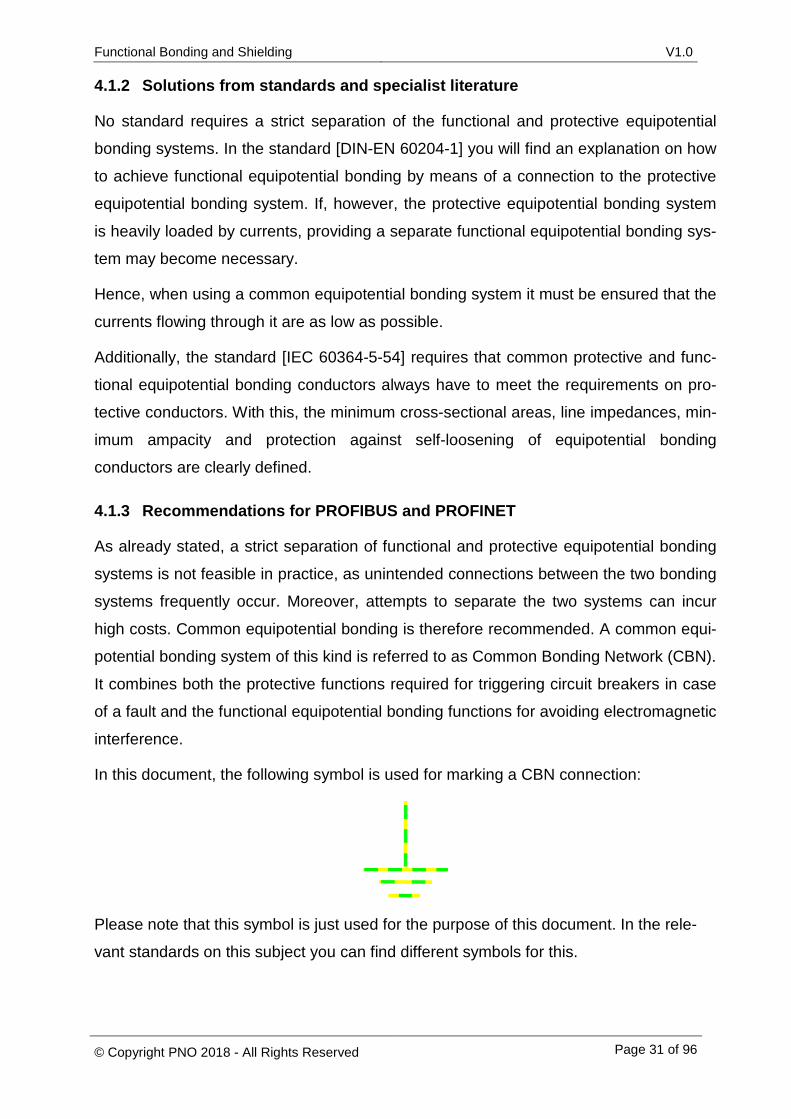
In this document, the following symbol is used for marking a CBN connection:
Please note that this symbol is just used for the purpose of this document. In the rele-
vant standards on this subject you can find different symbols for this.
Functional Bonding and Shielding V1.0
© Copyright PNO 2018 - All Rights Reserved Page 32 of 96
From this section of the document, the first recommendation R1 is derived:
4.2 Implementation of 230/400V mains supply
This section deals with the reduction of disturbances and loads of the equipotential
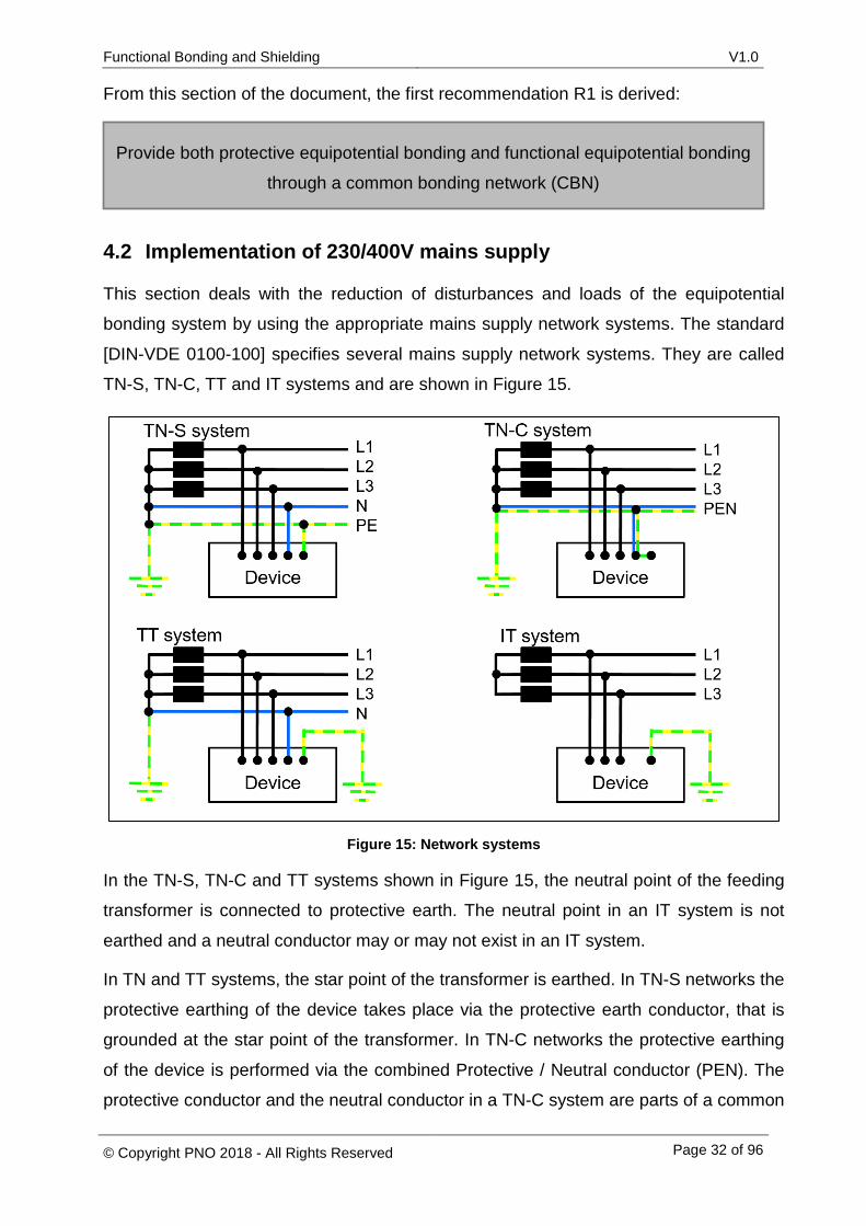
bonding system by using the appropriate mains supply network systems. The standard
[DIN-VDE 0100-100] specifies several mains supply network systems. They are called
TN-S, TN-C, TT and IT systems and are shown in Figure 15.
Figure 15: Network systems
In the TN-S, TN-C and TT systems shown in Figure 15, the neutral point of the feeding
transformer is connected to protective earth. The neutral point in an IT system is not
earthed and a neutral conductor may or may not exist in an IT system.
In TN and TT systems, the star point of the transformer is earthed. In TN-S networks the
protective earthing of the device takes place via the protective earth conductor, that is
grounded at the star point of the transformer. In TN-C networks the protective earthing
of the device is performed via the combined Protective / Neutral conductor (PEN). The
protective conductor and the neutral conductor in a TN-C system are parts of a common
Provide both protective equipotential bonding and functional equipotential bonding
through a common bonding network (CBN)
Functional Bonding and Shielding V1.0
© Copyright PNO 2018 - All Rights Reserved Page 33 of 96
conductor line. In a TN-S system, on the contrary, the protective conductor and the neu-
tral conductor are laid separately.
The neutral point in an IT system is not earthed.
In a TT system, the neutral point of the transformer is earthed. There is no protective
conductor connection between the neutral point of the transformer and the connected
devices. These are earthed locally. [SCH2008]
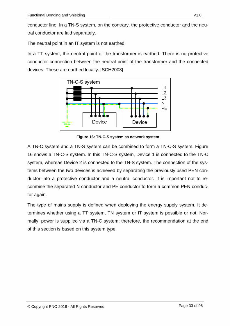
Figure 16: TN-C-S system as network system
A TN-C system and a TN-S system can be combined to form a TN-C-S system. Figure
16 shows a TN-C-S system. In this TN-C-S system, Device 1 is connected to the TN-C
system, whereas Device 2 is connected to the TN-S system. The connection of the sys-
tems between the two devices is achieved by separating the previously used PEN con-
ductor into a protective conductor and a neutral conductor. It is important not to re-
combine the separated N conductor and PE conductor to form a common PEN conduc-
tor again.
The type of mains supply is defined when deploying the energy supply system. It de-
termines whether using a TT system, TN system or IT system is possible or not. Nor-
mally, power is supplied via a TN-C system; therefore, the recommendation at the end
of this section is based on this system type.
Functional Bonding and Shielding V1.0
© Copyright PNO 2018 - All Rights Reserved Page 34 of 96
4.2.1 Problem descriptions
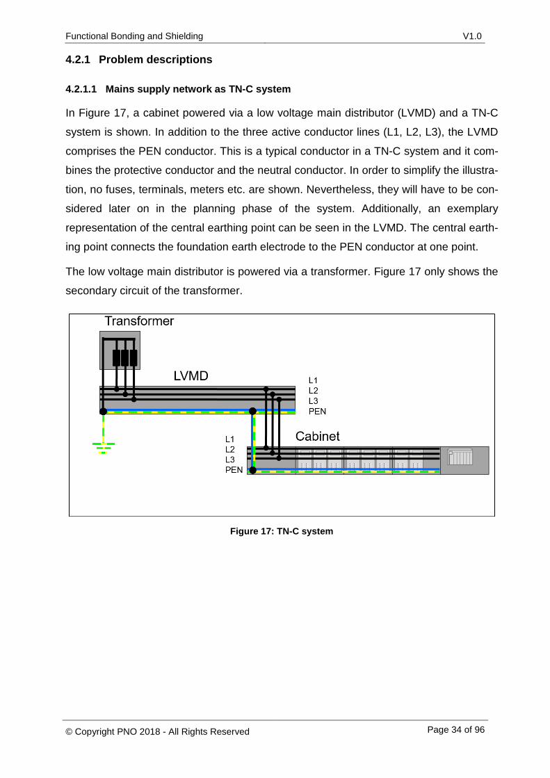
4.2.1.1 Mains supply network as TN-C system
In Figure 17, a cabinet powered via a low voltage main distributor (LVMD) and a TN-C
system is shown. In addition to the three active conductor lines (L1, L2, L3), the LVMD
comprises the PEN conductor. This is a typical conductor in a TN-C system and it com-
bines the protective conductor and the neutral conductor. In order to simplify the illustra-
tion, no fuses, terminals, meters etc. are shown. Nevertheless, they will have to be con-
sidered later on in the planning phase of the system. Additionally, an exemplary
representation of the central earthing point can be seen in the LVMD. The central earth-
ing point connects the foundation earth electrode to the PEN conductor at one point.
The low voltage main distributor is powered via a transformer. Figure 17 only shows the
secondary circuit of the transformer.
Figure 17: TN-C system
Functional Bonding and Shielding V1.0
© Copyright PNO 2018 - All Rights Reserved Page 35 of 96
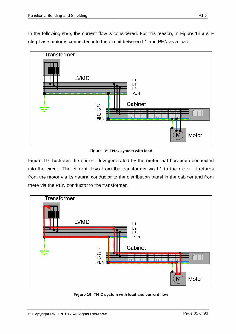
In the following step, the current flow is considered. For this reason, in Figure 18 a sin-
gle-phase motor is connected into the circuit between L1 and PEN as a load.
Figure 18: TN-C system with load
Figure 19 illustrates the current flow generated by the motor that has been connected
into the circuit. The current flows from the transformer via L1 to the motor. It returns
from the motor via its neutral conductor to the distribution panel in the cabinet and from
there via the PEN conductor to the transformer.
Figure 19: TN-C system with load and current flow
Functional Bonding and Shielding V1.0
© Copyright PNO 2018 - All Rights Reserved Page 36 of 96
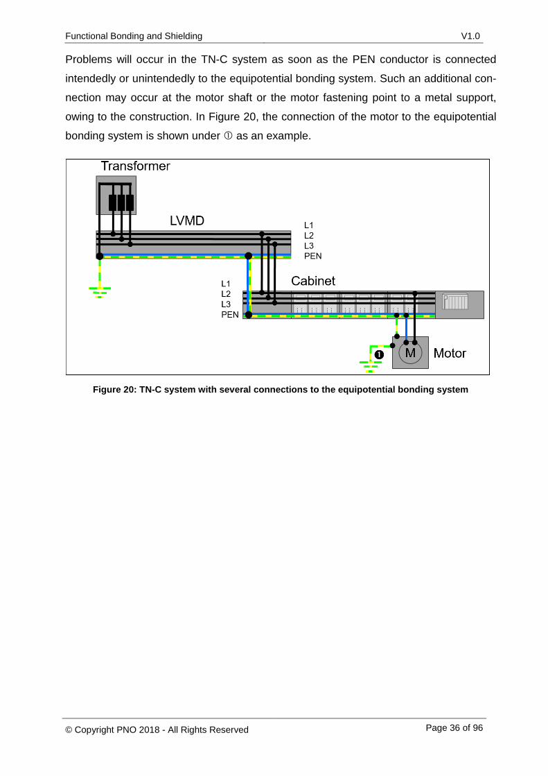
Problems will occur in the TN-C system as soon as the PEN conductor is connected
intendedly or unintendedly to the equipotential bonding system. Such an additional con-
nection may occur at the motor shaft or the motor fastening point to a metal support,
owing to the construction. In Figure 20, the connection of the motor to the equipotential
bonding system is shown under as an example.
Figure 20: TN-C system with several connections to the equipotential bonding system
Functional Bonding and Shielding V1.0
© Copyright PNO 2018 - All Rights Reserved Page 37 of 96
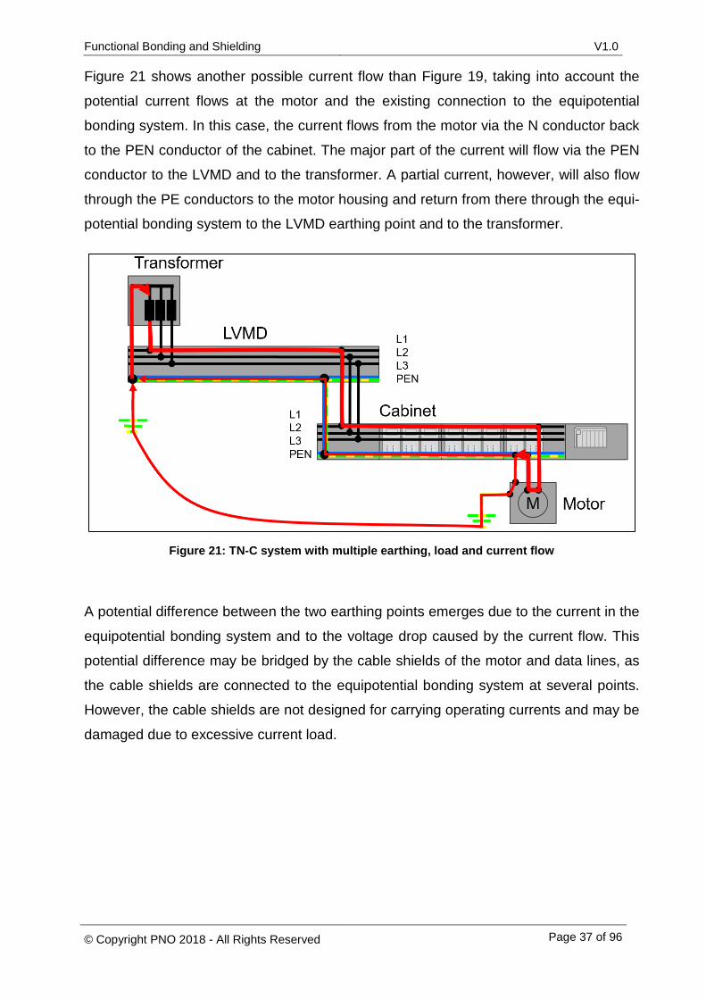
Figure 21 shows another possible current flow than Figure 19, taking into account the
potential current flows at the motor and the existing connection to the equipotential
bonding system. In this case, the current flows from the motor via the N conductor back
to the PEN conductor of the cabinet. The major part of the current will flow via the PEN
conductor to the LVMD and to the transformer. A partial current, however, will also flow
through the PE conductors to the motor housing and return from there through the equi-
potential bonding system to the LVMD earthing point and to the transformer.
Figure 21: TN-C system with multiple earthing, load and current flow
A potential difference between the two earthing points emerges due to the current in the
equipotential bonding system and to the voltage drop caused by the current flow. This
potential difference may be bridged by the cable shields of the motor and data lines, as
the cable shields are connected to the equipotential bonding system at several points.
However, the cable shields are not designed for carrying operating currents and may be
damaged due to excessive current load.
Functional Bonding and Shielding V1.0
© Copyright PNO 2018 - All Rights Reserved Page 38 of 96
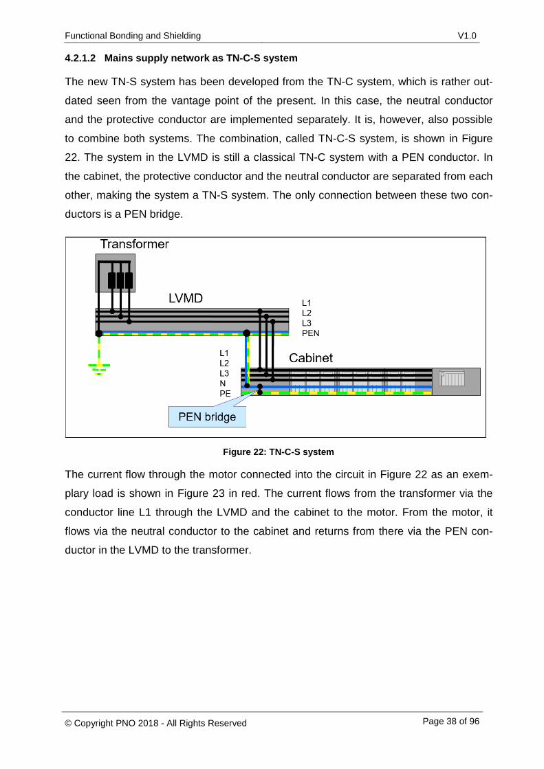
4.2.1.2 Mains supply network as TN-C-S system
The new TN-S system has been developed from the TN-C system, which is rather out-
dated seen from the vantage point of the present. In this case, the neutral conductor
and the protective conductor are implemented separately. It is, however, also possible
to combine both systems. The combination, called TN-C-S system, is shown in Figure
22. The system in the LVMD is still a classical TN-C system with a PEN conductor. In
the cabinet, the protective conductor and the neutral conductor are separated from each
other, making the system a TN-S system. The only connection between these two con-
ductors is a PEN bridge.
Figure 22: TN-C-S system
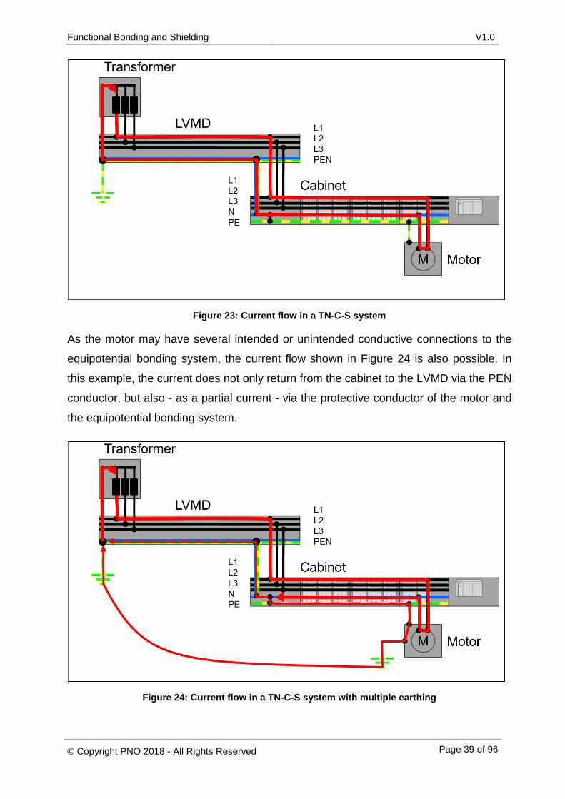
The current flow through the motor connected into the circuit in Figure 22 as an exem-
plary load is shown in Figure 23 in red. The current flows from the transformer via the
conductor line L1 through the LVMD and the cabinet to the motor. From the motor, it
flows via the neutral conductor to the cabinet and returns from there via the PEN con-
ductor in the LVMD to the transformer.
Functional Bonding and Shielding V1.0
© Copyright PNO 2018 - All Rights Reserved Page 39 of 96
Figure 23: Current flow in a TN-C-S system
As the motor may have several intended or unintended conductive connections to the
equipotential bonding system, the current flow shown in Figure 24 is also possible. In
this example, the current does not only return from the cabinet to the LVMD via the PEN
conductor, but also - as a partial current - via the protective conductor of the motor and
the equipotential bonding system.
Figure 24: Current flow in a TN-C-S system with multiple earthing
Functional Bonding and Shielding V1.0
© Copyright PNO 2018 - All Rights Reserved Page 40 of 96
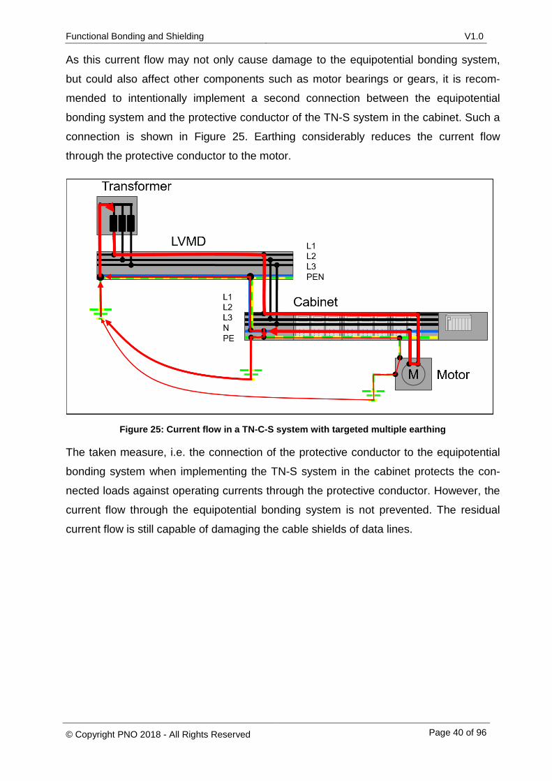
As this current flow may not only cause damage to the equipotential bonding system,
but could also affect other components such as motor bearings or gears, it is recom-
mended to intentionally implement a second connection between the equipotential
bonding system and the protective conductor of the TN-S system in the cabinet. Such a
connection is shown in Figure 25. Earthing considerably reduces the current flow
through the protective conductor to the motor.
Figure 25: Current flow in a TN-C-S system with targeted multiple earthing
The taken measure, i.e. the connection of the protective conductor to the equipotential
bonding system when implementing the TN-S system in the cabinet protects the con-
nected loads against operating currents through the protective conductor. However, the
current flow through the equipotential bonding system is not prevented. The residual
current flow is still capable of damaging the cable shields of data lines.
Functional Bonding and Shielding V1.0
© Copyright PNO 2018 - All Rights Reserved Page 41 of 96
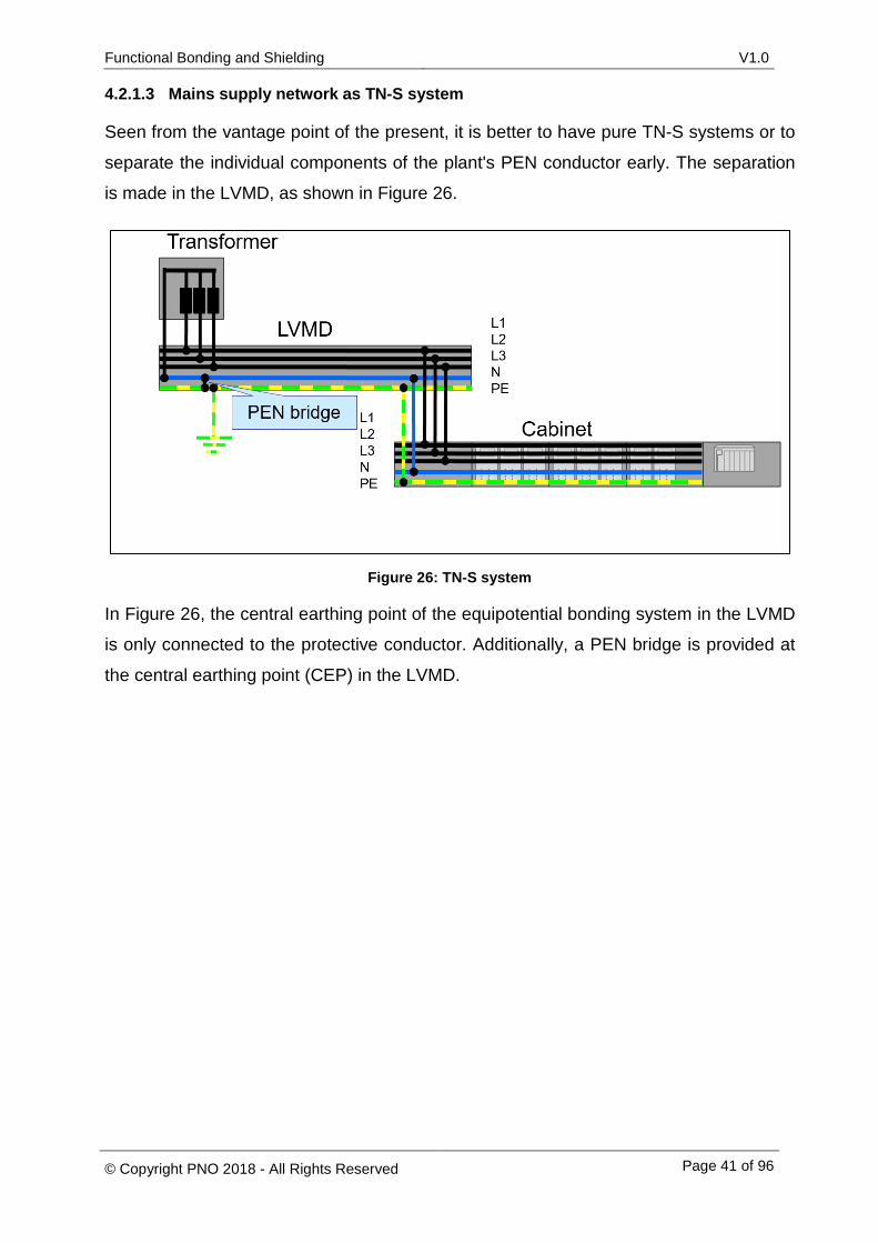
4.2.1.3 Mains supply network as TN-S system
Seen from the vantage point of the present, it is better to have pure TN-S systems or to
separate the individual components of the plant's PEN conductor early. The separation
is made in the LVMD, as shown in Figure 26.
Figure 26: TN-S system
In Figure 26, the central earthing point of the equipotential bonding system in the LVMD
is only connected to the protective conductor. Additionally, a PEN bridge is provided at
the central earthing point (CEP) in the LVMD.
Functional Bonding and Shielding V1.0
© Copyright PNO 2018 - All Rights Reserved Page 42 of 96
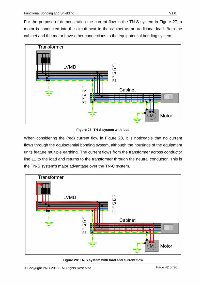
For the purpose of demonstrating the current flow in the TN-S system in Figure 27, a
motor is connected into the circuit next to the cabinet as an additional load. Both the
cabinet and the motor have other connections to the equipotential bonding system.
Figure 27: TN-S system with load
When considering the (red) current flow in Figure 28, it is noticeable that no current
flows through the equipotential bonding system, although the housings of the equipment
units feature multiple earthing. The current flows from the transformer across conductor
line L1 to the load and returns to the transformer through the neutral conductor. This is
the TN-S system's major advantage over the TN-C system.
Figure 28: TN-S system with load and current flow
Functional Bonding and Shielding V1.0
© Copyright PNO 2018 - All Rights Reserved Page 43 of 96
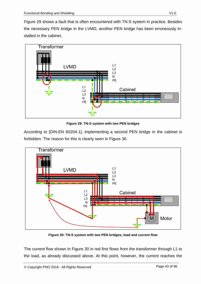
Figure 29 shows a fault that is often encountered with TN-S system in practice. Besides
the necessary PEN bridge in the LVMD, another PEN bridge has been erroneously in-
stalled in the cabinet.
Figure 29: TN-S system with two PEN bridges
According to [DIN-EN 60204-1], implementing a second PEN bridge in the cabinet is
forbidden. The reason for this is clearly seen in Figure 30.
Figure 30: TN-S system with two PEN bridges, load and current flow
The current flow shown in Figure 30 in red first flows from the transformer through L1 to
the load, as already discussed above. At this point, however, the current reaches the

Functional Bonding and Shielding V1.0
© Copyright PNO 2018 - All Rights Reserved Page 44 of 96
neutral conductor of the cabinet and flows to the incorrectly installed PEN bridge. At the
PEN bridge, the total current is divided into several partial currents. As a result, there is
a parallel back current via the equipotential bonding system, the protective conductor
and the neutral conductor to the transformer. The current flow in the equipotential bond-
ing system causes a potential difference between the two earthing points. This potential
difference creates difficulties, as it may cause, among other things, current flows in the
cables shields (see section 2.1.1).
Functional Bonding and Shielding V1.0
© Copyright PNO 2018 - All Rights Reserved Page 45 of 96
4.2.2 Descriptions in the relevant standards and specialist literature
According to [DIN-EN 50310] and [IEC 60364-4-44], TN-C systems are not suitable for
installations in buildings with IT equipment, due to non-compliance with EMC require-
ments. This is mainly due to the PEN conductor. For operational reasons, the PEN con-
ductor leads neutral conductor currents which may cause potential differences in the
equipotential bonding system due to multiple connections with it. Moreover, the currents
in the equipotential bonding system also flow through the cable shields of motor and
data lines which have to be earthed at each end in order to ensure their active shielding
effect. The currents flowing in the cable shields cause disturbances in the plant
[SCH2008], because they affect the communication between the connected devices.
These disturbances may even result in plant down times.
For this reason, the designers and constructors of new buildings/plants with IT equip-
ment are requested in [DIN-EN 50310] and [IEC 60364-4-44] to use TN-S systems only.
Functional Bonding and Shielding V1.0
© Copyright PNO 2018 - All Rights Reserved Page 46 of 96
4.2.3 Recommendations for PROFIBUS and PROFINET
Due to the advancing digitalization in the process and manufacturing industries, it must
be assumed that all buildings in manufacturing plants (will) have IT equipment. To en-
sure electromagnetic compatibility, it is recommended to use only TN-S systems, TN-C-
S-systems, where the PE and the N conductor are preferably already separated in the
LVMD or TT-systems. If a TN-C system exists already for power supply from the energy
supply company, it should be converted into a TN-S system in the low voltage main dis-
tributor system as early as possible, for EMC reasons. To achieve this, a PEN bridge
should be installed close to the central earthing point. In a TN-S system, there may be
several parallel connections, for example from the cabinet to the equipotential bonding
system, without any operating currents flowing through the equipotential bonding sys-
tem.
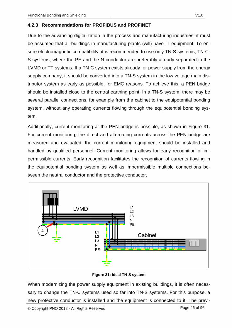
Additionally, current monitoring at the PEN bridge is possible, as shown in Figure 31.
For current monitoring, the direct and alternating currents across the PEN bridge are
measured and evaluated; the current monitoring equipment should be installed and
handled by qualified personnel. Current monitoring allows for early recognition of im-
permissible currents. Early recognition facilitates the recognition of currents flowing in
the equipotential bonding system as well as impermissible multiple connections be-
tween the neutral conductor and the protective conductor.
Figure 31: Ideal TN-S system
When modernizing the power supply equipment in existing buildings, it is often neces-
sary to change the TN-C systems used so far into TN-S systems. For this purpose, a
new protective conductor is installed and the equipment is connected to it. The previ-

Functional Bonding and Shielding V1.0
© Copyright PNO 2018 - All Rights Reserved Page 47 of 96
ously used PEN conductor can only be re-used as a neutral conductor, provided that it
has an appropriate cross sectional area (CSA) and is in a re-usable state. It must be
ensured that there is only one connection between the protective conductor and the
previously used PEN conductor in the LVMD. Any additional connection must be avoid-
ed in the TN-S system [WOL2015].
From this section of the document, the second recommendation R2 is derived:
Preferably use a 230/400 V power supply using a TN-S system.
Functional Bonding and Shielding V1.0
© Copyright PNO 2018 - All Rights Reserved Page 48 of 96
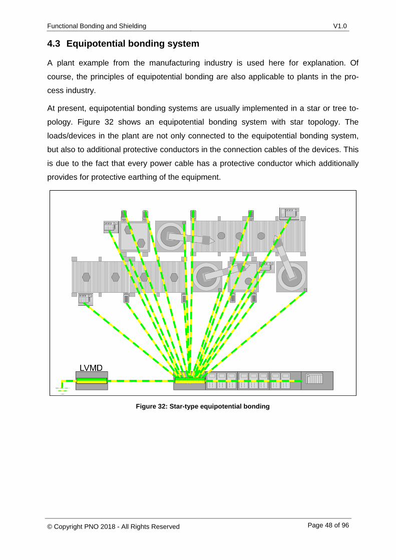
4.3 Equipotential bonding system
A plant example from the manufacturing industry is used here for explanation. Of
course, the principles of equipotential bonding are also applicable to plants in the pro-
cess industry.
At present, equipotential bonding systems are usually implemented in a star or tree to-
pology. Figure 32 shows an equipotential bonding system with star topology. The
loads/devices in the plant are not only connected to the equipotential bonding system,
but also to additional protective conductors in the connection cables of the devices. This
is due to the fact that every power cable has a protective conductor which additionally
provides for protective earthing of the equipment.
Figure 32: Star-type equipotential bonding
Functional Bonding and Shielding V1.0
© Copyright PNO 2018 - All Rights Reserved Page 49 of 96
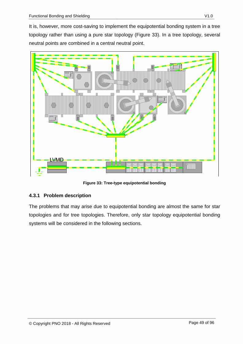
It is, however, more cost-saving to implement the equipotential bonding system in a tree
topology rather than using a pure star topology (Figure 33). In a tree topology, several
neutral points are combined in a central neutral point.
Figure 33: Tree-type equipotential bonding
4.3.1 Problem description
The problems that may arise due to equipotential bonding are almost the same for star
topologies and for tree topologies. Therefore, only star topology equipotential bonding
systems will be considered in the following sections.
Functional Bonding and Shielding V1.0
© Copyright PNO 2018 - All Rights Reserved Page 50 of 96
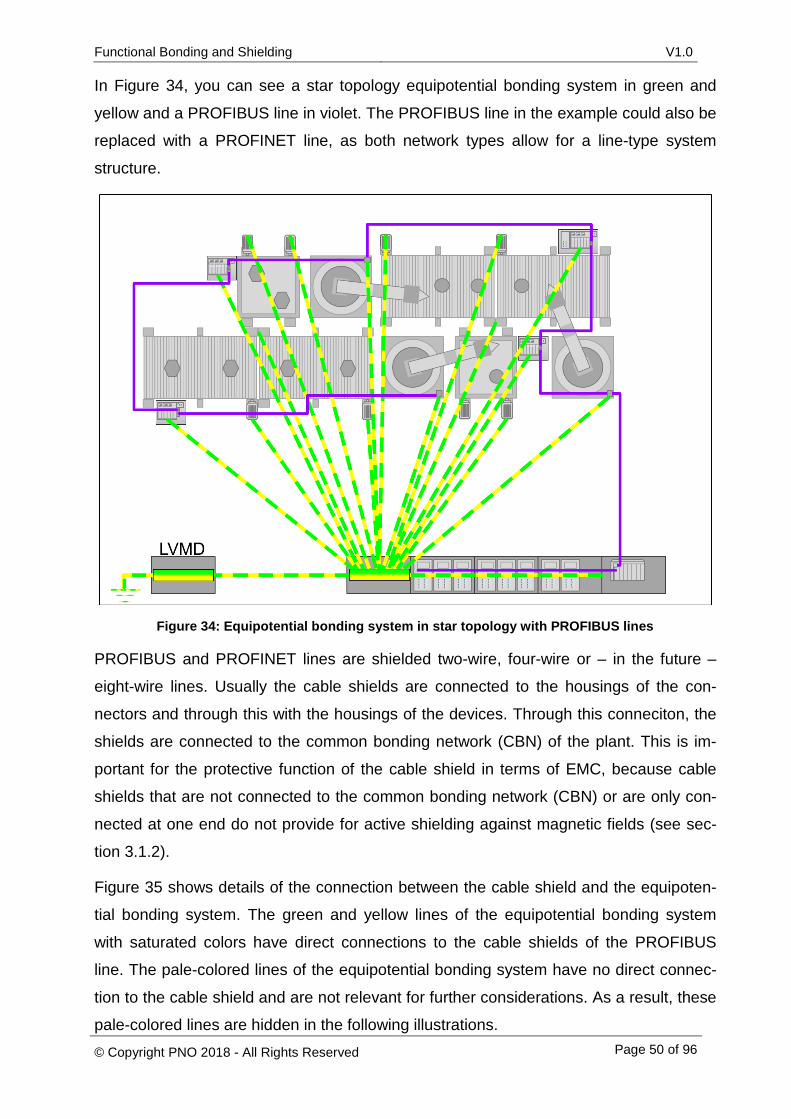
In Figure 34, you can see a star topology equipotential bonding system in green and
yellow and a PROFIBUS line in violet. The PROFIBUS line in the example could also be
replaced with a PROFINET line, as both network types allow for a line-type system
structure.
Figure 34: Equipotential bonding system in star topology with PROFIBUS lines
PROFIBUS and PROFINET lines are shielded two-wire, four-wire or – in the future –
eight-wire lines. Usually the cable shields are connected to the housings of the con-
nectors and through this with the housings of the devices. Through this conneciton, the
shields are connected to the common bonding network (CBN) of the plant. This is im-
portant for the protective function of the cable shield in terms of EMC, because cable
shields that are not connected to the common bonding network (CBN) or are only con-
nected at one end do not provide for active shielding against magnetic fields (see sec-
tion 3.1.2).
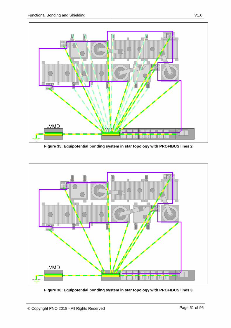
Figure 35 shows details of the connection between the cable shield and the equipoten-
tial bonding system. The green and yellow lines of the equipotential bonding system
with saturated colors have direct connections to the cable shields of the PROFIBUS
line. The pale-colored lines of the equipotential bonding system have no direct connec-
tion to the cable shield and are not relevant for further considerations. As a result, these
pale-colored lines are hidden in the following illustrations.
Functional Bonding and Shielding V1.0
© Copyright PNO 2018 - All Rights Reserved Page 51 of 96
Figure 35: Equipotential bonding system in star topology with PROFIBUS lines 2
Figure 36: Equipotential bonding system in star topology with PROFIBUS lines 3
Functional Bonding and Shielding V1.0
© Copyright PNO 2018 - All Rights Reserved Page 52 of 96
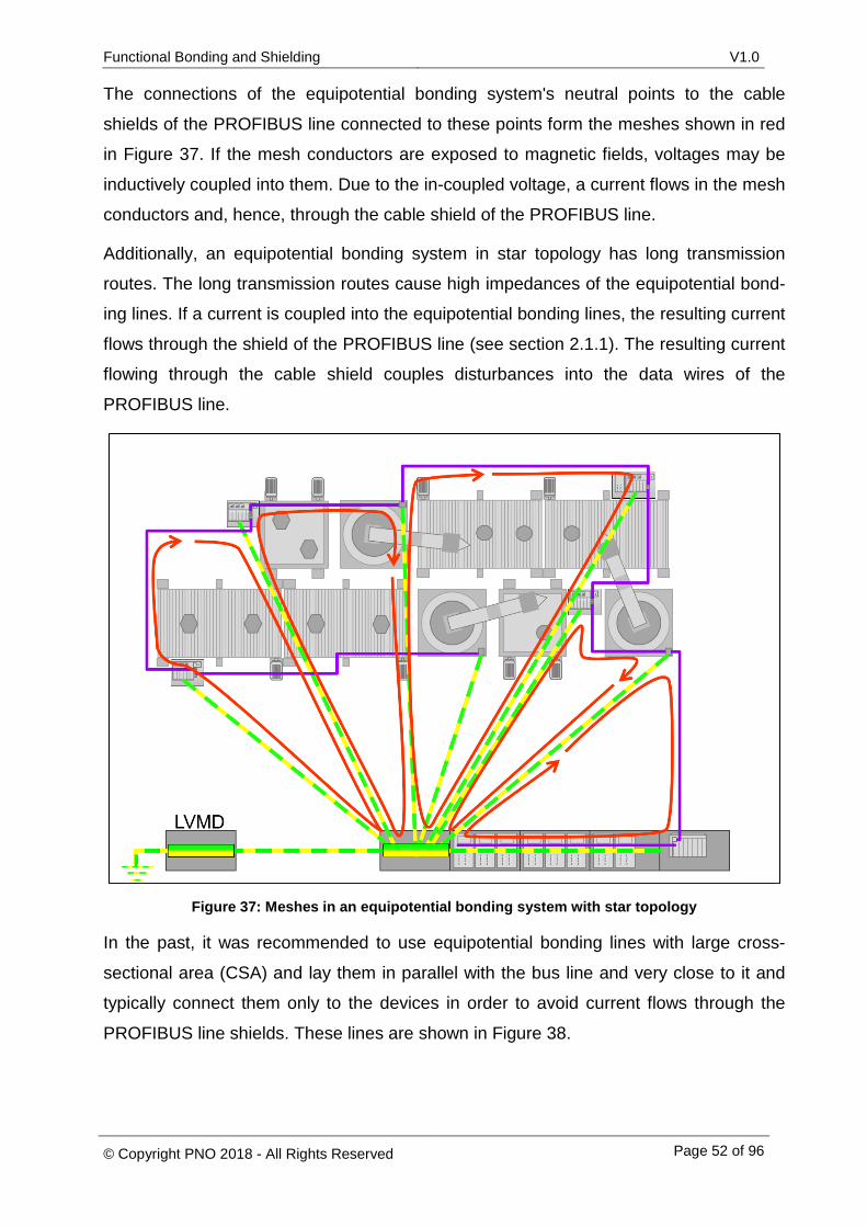
The connections of the equipotential bonding system's neutral points to the cable
shields of the PROFIBUS line connected to these points form the meshes shown in red
in Figure 37. If the mesh conductors are exposed to magnetic fields, voltages may be
inductively coupled into them. Due to the in-coupled voltage, a current flows in the mesh
conductors and, hence, through the cable shield of the PROFIBUS line.
Additionally, an equipotential bonding system in star topology has long transmission
routes. The long transmission routes cause high impedances of the equipotential bond-
ing lines. If a current is coupled into the equipotential bonding lines, the resulting current
flows through the shield of the PROFIBUS line (see section 2.1.1). The resulting current
flowing through the cable shield couples disturbances into the data wires of the
PROFIBUS line.
Figure 37: Meshes in an equipotential bonding system with star topology
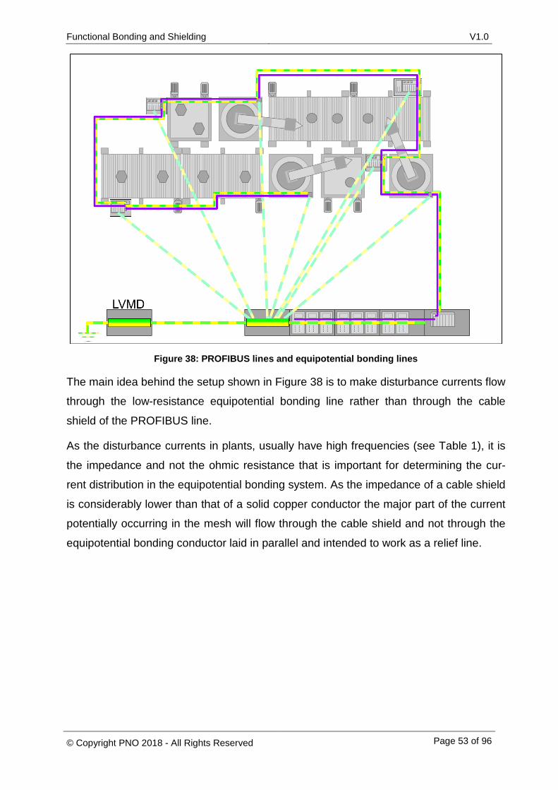
In the past, it was recommended to use equipotential bonding lines with large cross-
sectional area (CSA) and lay them in parallel with the bus line and very close to it and
typically connect them only to the devices in order to avoid current flows through the
PROFIBUS line shields. These lines are shown in Figure 38.
Functional Bonding and Shielding V1.0
© Copyright PNO 2018 - All Rights Reserved Page 53 of 96
Figure 38: PROFIBUS lines and equipotential bonding lines
The main idea behind the setup shown in Figure 38 is to make disturbance currents flow
through the low-resistance equipotential bonding line rather than through the cable
shield of the PROFIBUS line.
As the disturbance currents in plants, usually have high frequencies (see Table 1), it is
the impedance and not the ohmic resistance that is important for determining the cur-
rent distribution in the equipotential bonding system. As the impedance of a cable shield
is considerably lower than that of a solid copper conductor the major part of the current
potentially occurring in the mesh will flow through the cable shield and not through the
equipotential bonding conductor laid in parallel and intended to work as a relief line.
Functional Bonding and Shielding V1.0
© Copyright PNO 2018 - All Rights Reserved Page 54 of 96
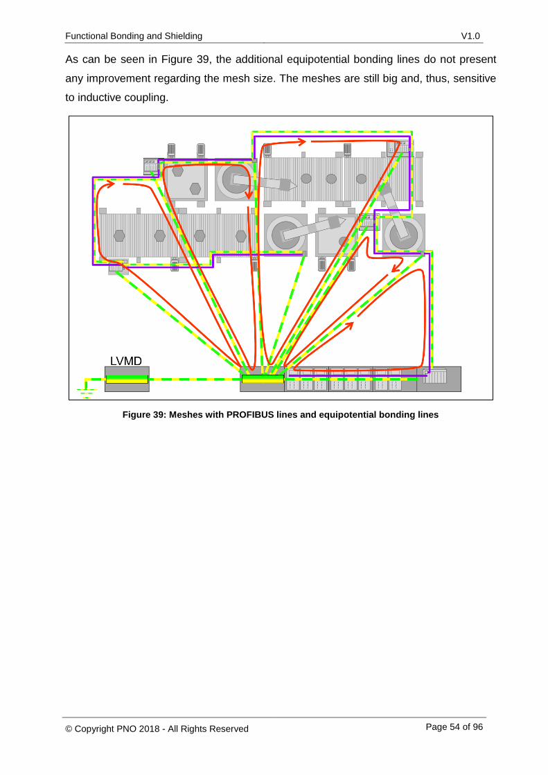
As can be seen in Figure 39, the additional equipotential bonding lines do not present
any improvement regarding the mesh size. The meshes are still big and, thus, sensitive
to inductive coupling.
Figure 39: Meshes with PROFIBUS lines and equipotential bonding lines
Functional Bonding and Shielding V1.0
© Copyright PNO 2018 - All Rights Reserved Page 55 of 96
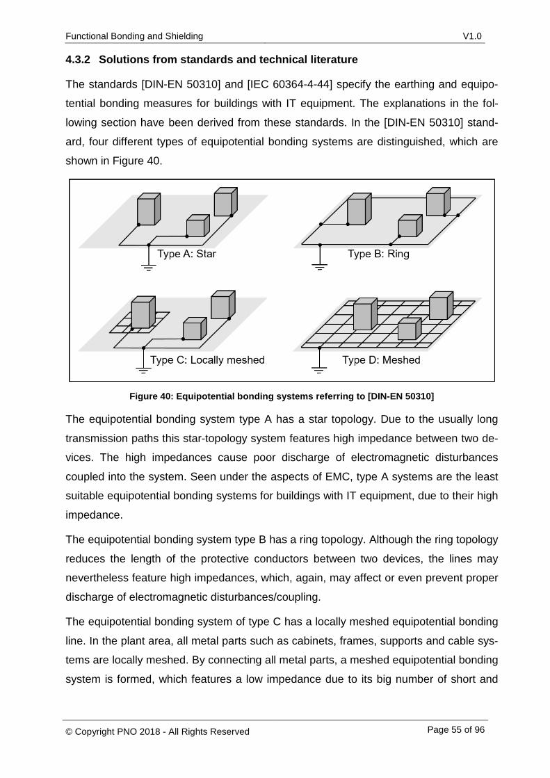
4.3.2 Solutions from standards and technical literature
The standards [DIN-EN 50310] and [IEC 60364-4-44] specify the earthing and equipo-
tential bonding measures for buildings with IT equipment. The explanations in the fol-
lowing section have been derived from these standards. In the [DIN-EN 50310] stand-
ard, four different types of equipotential bonding systems are distinguished, which are
shown in Figure 40.
Figure 40: Equipotential bonding systems referring to [DIN-EN 50310]
The equipotential bonding system type A has a star topology. Due to the usually long
transmission paths this star-topology system features high impedance between two de-
vices. The high impedances cause poor discharge of electromagnetic disturbances
coupled into the system. Seen under the aspects of EMC, type A systems are the least
suitable equipotential bonding systems for buildings with IT equipment, due to their high
impedance.
The equipotential bonding system type B has a ring topology. Although the ring topology
reduces the length of the protective conductors between two devices, the lines may
nevertheless feature high impedances, which, again, may affect or even prevent proper
discharge of electromagnetic disturbances/coupling.
The equipotential bonding system of type C has a locally meshed equipotential bonding
line. In the plant area, all metal parts such as cabinets, frames, supports and cable sys-
tems are locally meshed. By connecting all metal parts, a meshed equipotential bonding
system is formed, which features a low impedance due to its big number of short and
Functional Bonding and Shielding V1.0
© Copyright PNO 2018 - All Rights Reserved Page 56 of 96
parallel transmission routes. A network with this kind of meshing of all conductive ob-
jects is called a Bonding Network (BN).
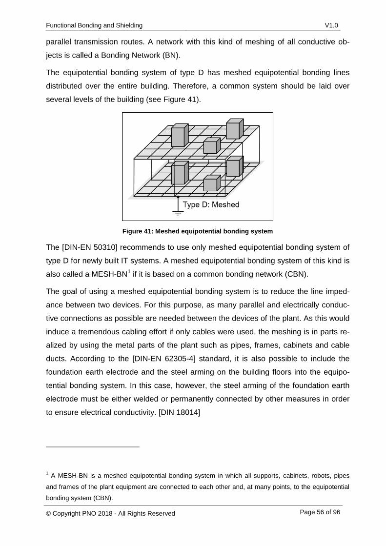
The equipotential bonding system of type D has meshed equipotential bonding lines
distributed over the entire building. Therefore, a common system should be laid over
several levels of the building (see Figure 41).
Figure 41: Meshed equipotential bonding system
The [DIN-EN 50310] recommends to use only meshed equipotential bonding system of
type D for newly built IT systems. A meshed equipotential bonding system of this kind is
also called a MESH-BN1 if it is based on a common bonding network (CBN).
The goal of using a meshed equipotential bonding system is to reduce the line imped-
ance between two devices. For this purpose, as many parallel and electrically conduc-
tive connections as possible are needed between the devices of the plant. As this would
induce a tremendous cabling effort if only cables were used, the meshing is in parts re-
alized by using the metal parts of the plant such as pipes, frames, cabinets and cable
ducts. According to the [DIN-EN 62305-4] standard, it is also possible to include the
foundation earth electrode and the steel arming on the building floors into the equipo-
tential bonding system. In this case, however, the steel arming of the foundation earth
electrode must be either welded or permanently connected by other measures in order
to ensure electrical conductivity. [DIN 18014]
1 A MESH-BN is a meshed equipotential bonding system in which all supports, cabinets, robots, pipes
and frames of the plant equipment are connected to each other and, at many points, to the equipotential
bonding system (CBN).
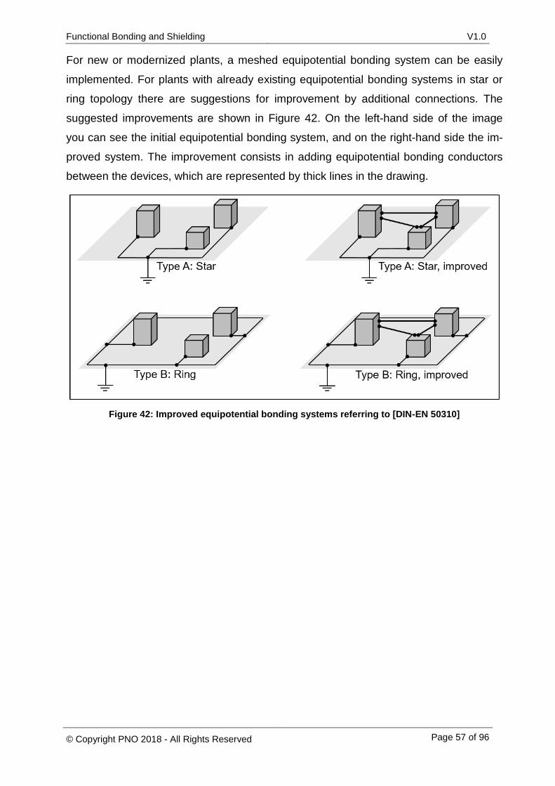
Functional Bonding and Shielding V1.0
© Copyright PNO 2018 - All Rights Reserved Page 57 of 96
For new or modernized plants, a meshed equipotential bonding system can be easily
implemented. For plants with already existing equipotential bonding systems in star or
ring topology there are suggestions for improvement by additional connections. The
suggested improvements are shown in Figure 42. On the left-hand side of the image
you can see the initial equipotential bonding system, and on the right-hand side the im-
proved system. The improvement consists in adding equipotential bonding conductors
between the devices, which are represented by thick lines in the drawing.
Figure 42: Improved equipotential bonding systems referring to [DIN-EN 50310]
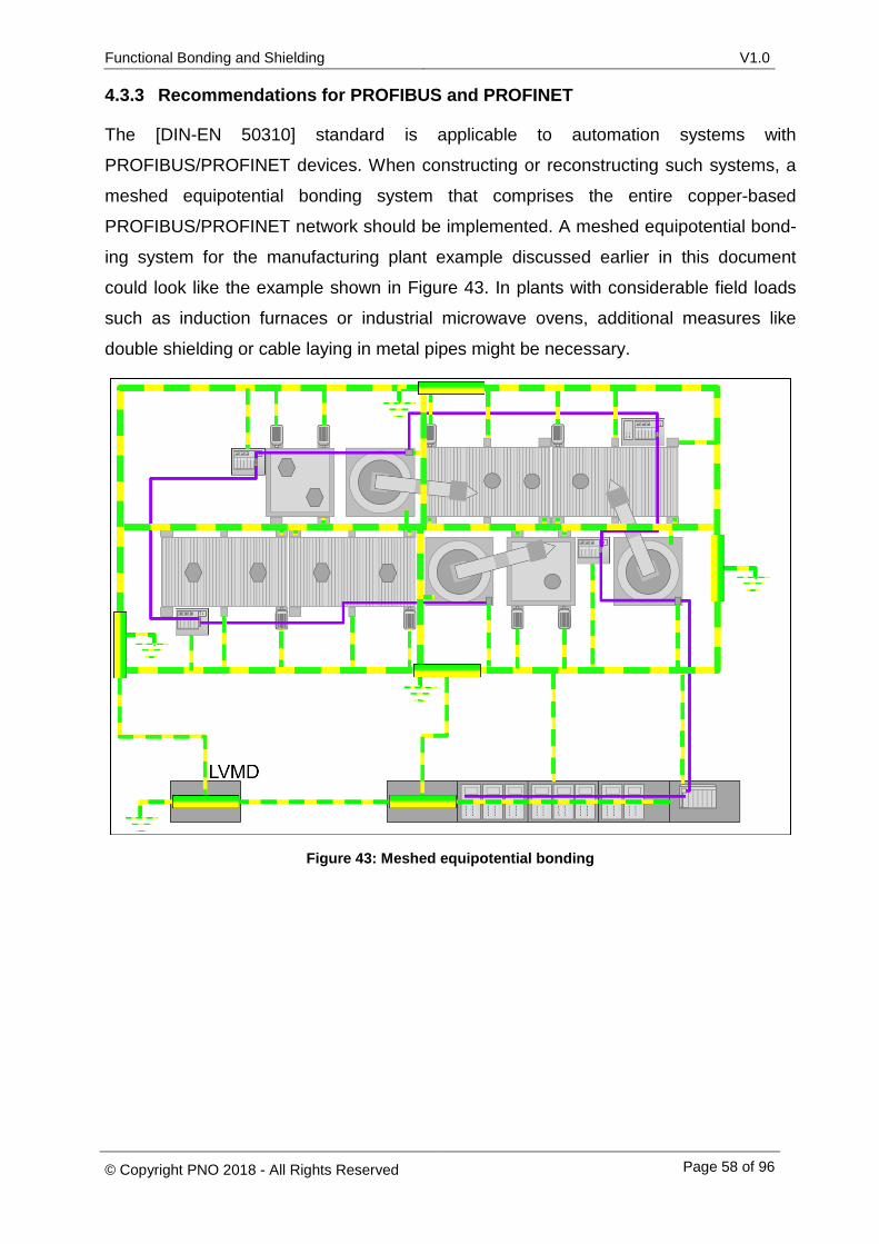
Functional Bonding and Shielding V1.0
© Copyright PNO 2018 - All Rights Reserved Page 58 of 96
4.3.3 Recommendations for PROFIBUS and PROFINET
The [DIN-EN 50310] standard is applicable to automation systems with
PROFIBUS/PROFINET devices. When constructing or reconstructing such systems, a
meshed equipotential bonding system that comprises the entire copper-based
PROFIBUS/PROFINET network should be implemented. A meshed equipotential bond-
ing system for the manufacturing plant example discussed earlier in this document
could look like the example shown in Figure 43. In plants with considerable field loads
such as induction furnaces or industrial microwave ovens, additional measures like
double shielding or cable laying in metal pipes might be necessary.
Figure 43: Meshed equipotential bonding
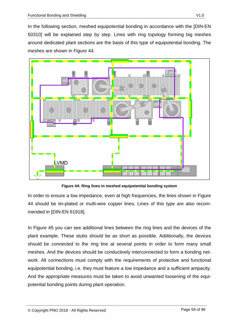
Functional Bonding and Shielding V1.0
© Copyright PNO 2018 - All Rights Reserved Page 59 of 96
In the following section, meshed equipotential bonding in accordance with the [DIN-EN
50310] will be explained step by step. Lines with ring topology forming big meshes
around dedicated plant sections are the basis of this type of equipotential bonding. The
meshes are shown in Figure 44.
Figure 44: Ring lines in meshed equipotential bonding system
In order to ensure a low impedance, even at high frequencies, the lines shown in Figure
44 should be tin-plated or multi-wire copper lines. Lines of this type are also recom-
mended in [DIN-EN 61918].
In Figure 45 you can see additional lines between the ring lines and the devices of the
plant example. These stubs should be as short as possible. Additionally, the devices
should be connected to the ring line at several points in order to form many small
meshes. And the devices should be conductively interconnected to form a bonding net-
work. All connections must comply with the requirements of protective and functional
equipotential bonding, i.e. they must feature a low impedance and a sufficient ampacity.
And the appropriate measures must be taken to avoid unwanted loosening of the equi-
potential bonding points during plant operation.
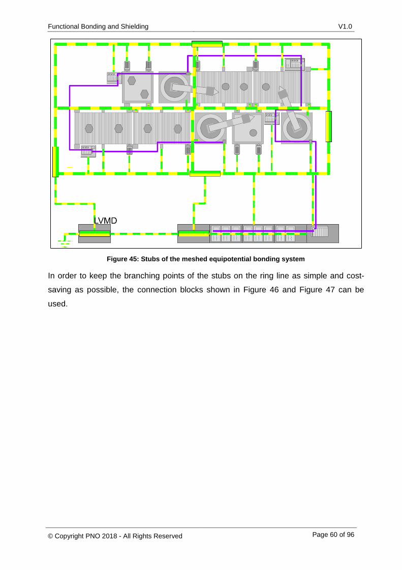
Functional Bonding and Shielding V1.0
© Copyright PNO 2018 - All Rights Reserved Page 60 of 96
Figure 45: Stubs of the meshed equipotential bonding system
In order to keep the branching points of the stubs on the ring line as simple and cost-
saving as possible, the connection blocks shown in Figure 46 and Figure 47 can be
used.
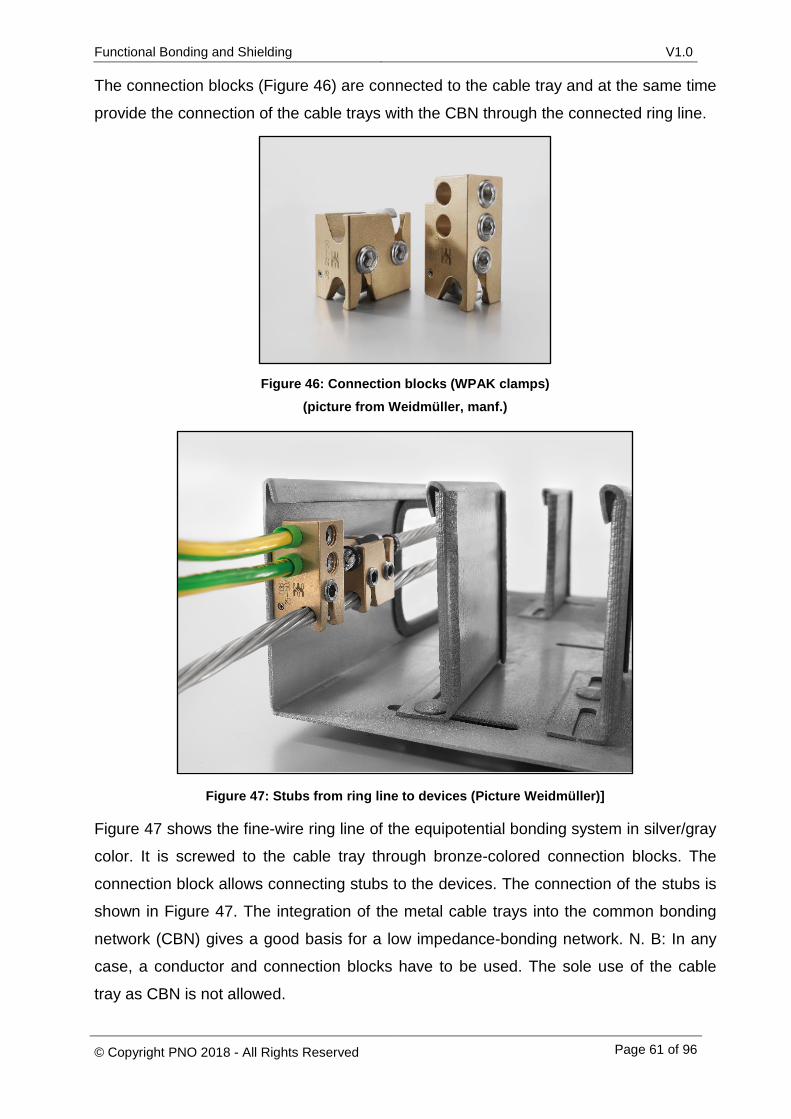
Functional Bonding and Shielding V1.0
© Copyright PNO 2018 - All Rights Reserved Page 61 of 96
The connection blocks (Figure 46) are connected to the cable tray and at the same time
provide the connection of the cable trays with the CBN through the connected ring line.
Figure 46: Connection blocks (WPAK clamps) (picture from Weidmüller, manf.)
Figure 47: Stubs from ring line to devices (Picture Weidmüller)]
Figure 47 shows the fine-wire ring line of the equipotential bonding system in silver/gray
color. It is screwed to the cable tray through bronze-colored connection blocks. The
connection block allows connecting stubs to the devices. The connection of the stubs is
shown in Figure 47. The integration of the metal cable trays into the common bonding
network (CBN) gives a good basis for a low impedance-bonding network. N. B: In any
case, a conductor and connection blocks have to be used. The sole use of the cable
tray as CBN is not allowed.
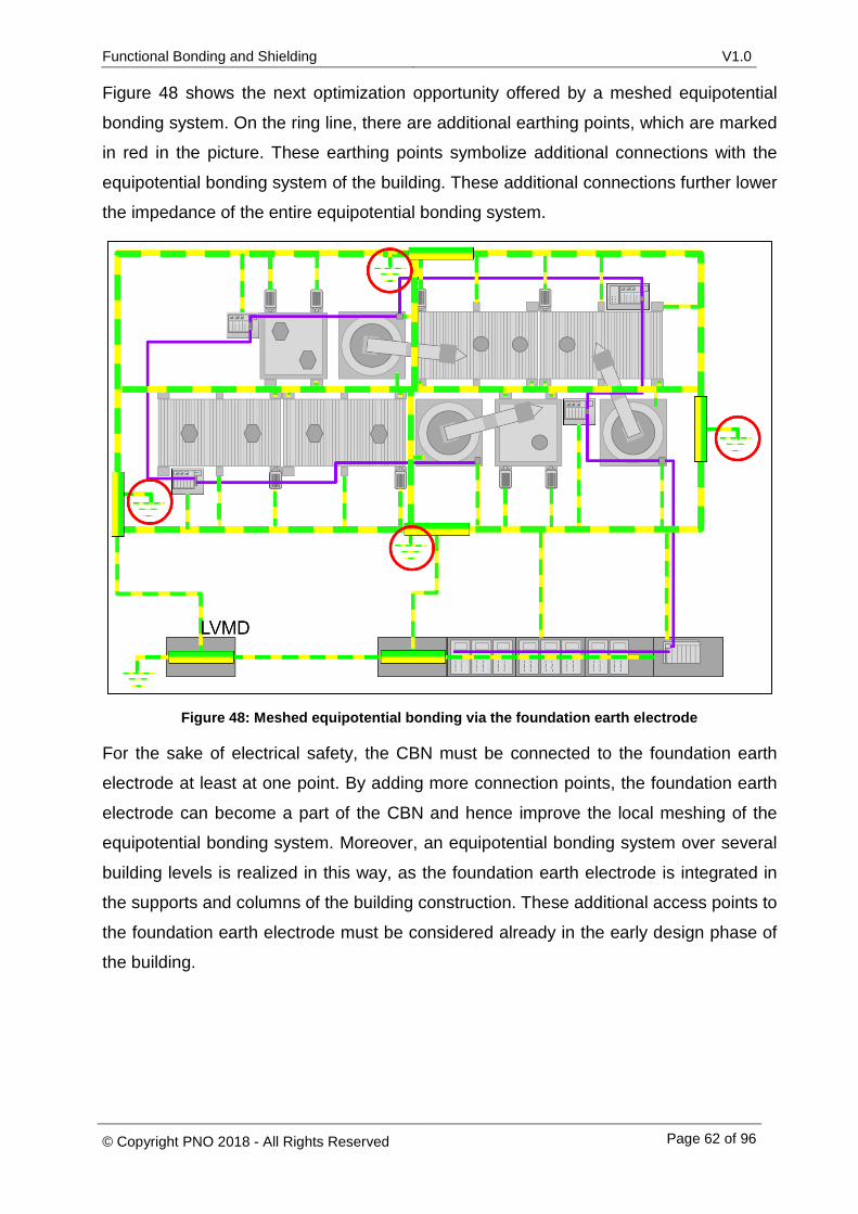
Functional Bonding and Shielding V1.0
© Copyright PNO 2018 - All Rights Reserved Page 62 of 96
Figure 48 shows the next optimization opportunity offered by a meshed equipotential
bonding system. On the ring line, there are additional earthing points, which are marked
in red in the picture. These earthing points symbolize additional connections with the
equipotential bonding system of the building. These additional connections further lower
the impedance of the entire equipotential bonding system.
Figure 48: Meshed equipotential bonding via the foundation earth electrode
For the sake of electrical safety, the CBN must be connected to the foundation earth
electrode at least at one point. By adding more connection points, the foundation earth
electrode can become a part of the CBN and hence improve the local meshing of the
equipotential bonding system. Moreover, an equipotential bonding system over several
building levels is realized in this way, as the foundation earth electrode is integrated in
the supports and columns of the building construction. These additional access points to
the foundation earth electrode must be considered already in the early design phase of
the building.
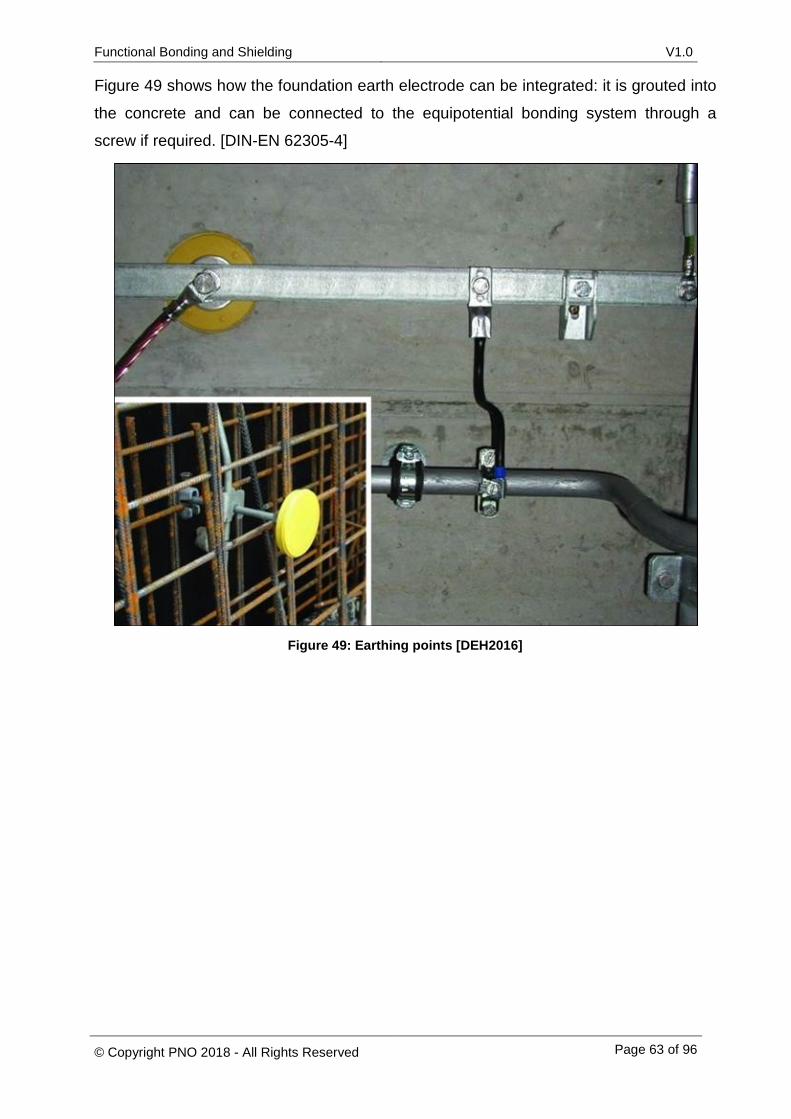
Functional Bonding and Shielding V1.0
© Copyright PNO 2018 - All Rights Reserved Page 63 of 96
Figure 49 shows how the foundation earth electrode can be integrated: it is grouted into
the concrete and can be connected to the equipotential bonding system through a
screw if required. [DIN-EN 62305-4]
Figure 49: Earthing points [DEH2016]
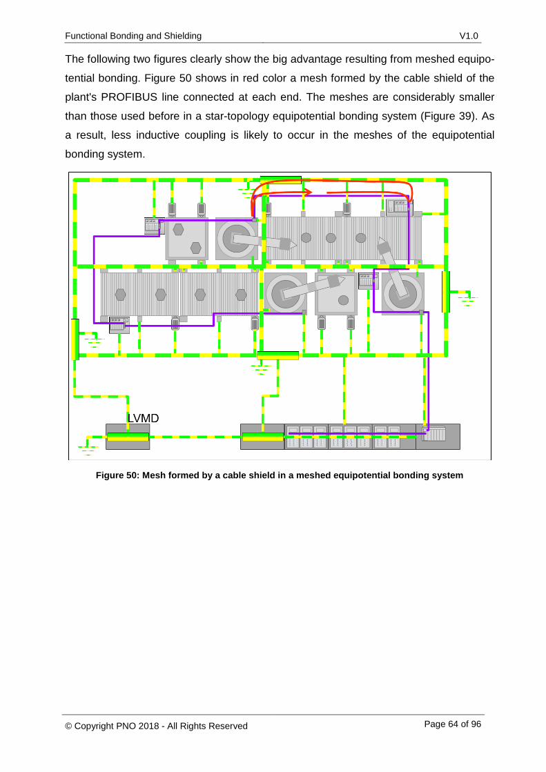
Functional Bonding and Shielding V1.0
© Copyright PNO 2018 - All Rights Reserved Page 64 of 96
The following two figures clearly show the big advantage resulting from meshed equipo-
tential bonding. Figure 50 shows in red color a mesh formed by the cable shield of the
plant's PROFIBUS line connected at each end. The meshes are considerably smaller
than those used before in a star-topology equipotential bonding system (Figure 39). As
a result, less inductive coupling is likely to occur in the meshes of the equipotential
bonding system.
Figure 50: Mesh formed by a cable shield in a meshed equipotential bonding system
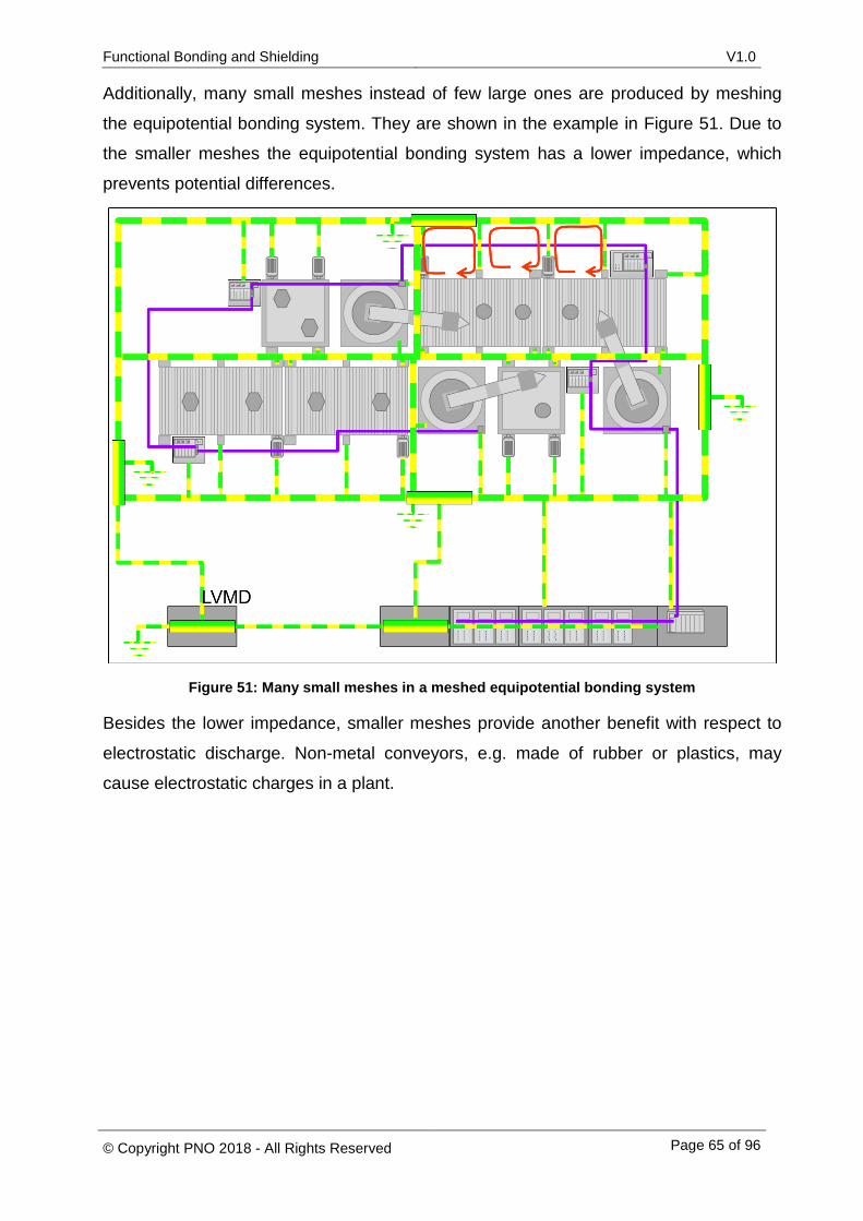
Functional Bonding and Shielding V1.0
© Copyright PNO 2018 - All Rights Reserved Page 65 of 96
Additionally, many small meshes instead of few large ones are produced by meshing
the equipotential bonding system. They are shown in the example in Figure 51. Due to
the smaller meshes the equipotential bonding system has a lower impedance, which
prevents potential differences.
Figure 51: Many small meshes in a meshed equipotential bonding system
Besides the lower impedance, smaller meshes provide another benefit with respect to
electrostatic discharge. Non-metal conveyors, e.g. made of rubber or plastics, may
cause electrostatic charges in a plant.
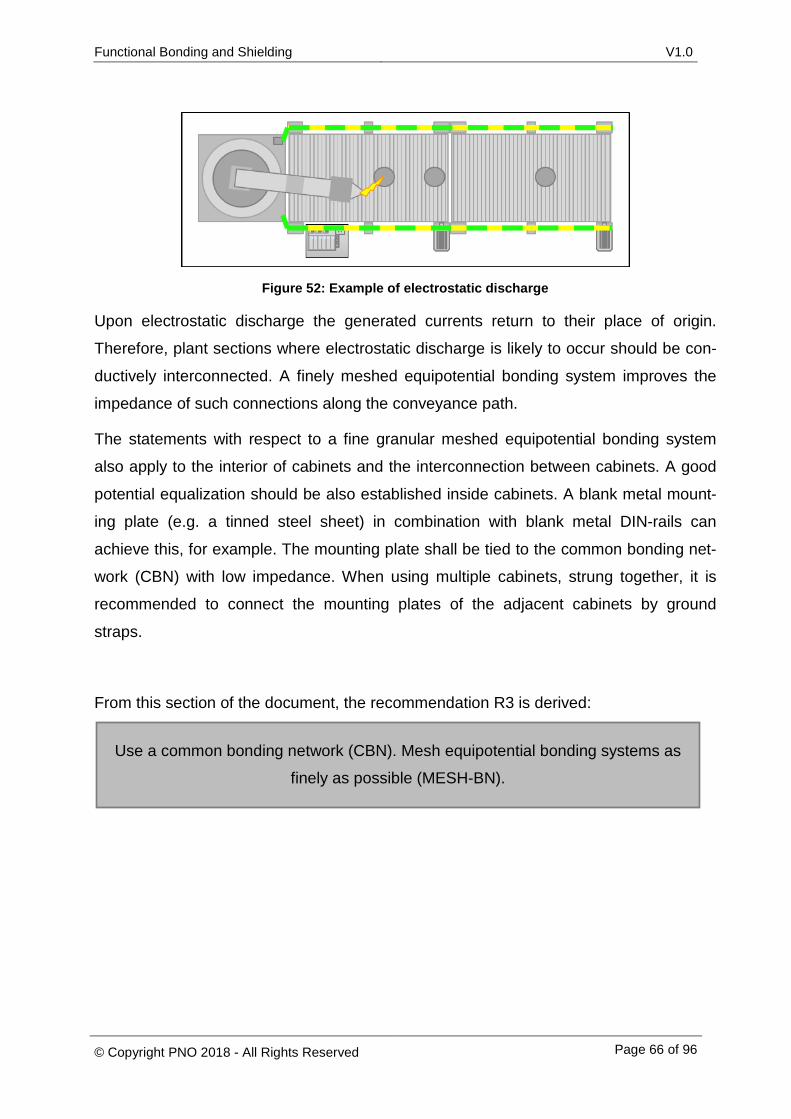
Functional Bonding and Shielding V1.0
© Copyright PNO 2018 - All Rights Reserved Page 66 of 96
Figure 52: Example of electrostatic discharge
Upon electrostatic discharge the generated currents return to their place of origin.
Therefore, plant sections where electrostatic discharge is likely to occur should be con-
ductively interconnected. A finely meshed equipotential bonding system improves the
impedance of such connections along the conveyance path.
The statements with respect to a fine granular meshed equipotential bonding system
also apply to the interior of cabinets and the interconnection between cabinets. A good
potential equalization should be also established inside cabinets. A blank metal mount-
ing plate (e.g. a tinned steel sheet) in combination with blank metal DIN-rails can
achieve this, for example. The mounting plate shall be tied to the common bonding net-
work (CBN) with low impedance. When using multiple cabinets, strung together, it is
recommended to connect the mounting plates of the adjacent cabinets by ground
straps.
From this section of the document, the recommendation R3 is derived:
Use a common bonding network (CBN). Mesh equipotential bonding systems as
finely as possible (MESH-BN).
Functional Bonding and Shielding V1.0
© Copyright PNO 2018 - All Rights Reserved Page 67 of 96
4.4 Connection of PROFIBUS/PROFINET cable shields
The PROFIBUS or PROFINET cable shields are connected through the connector plug.
Inside the connector, the cable shield is connected to the connector housing. The con-
nector housing is connected to the equipotential bonding system, usually via the con-
nector plug and the connected device.
4.4.1 Problem description with solutions from standards and technical literature
As the cable shield makes use of the active shielding principle, the shield should be
connected to the equipotential bonding system at least at each end. Only then the cur-
rents generated by electromagnetic interference can flow through the cable shield and
generate an opposing field. This opposing field produces a nearly field-free area inside
the cable shield. By virtue of the field-free area, no disturbances are coupled into the
data wires. Caution: Cables shields connected at both ends of a line may cause prob-
lems in hazardous areas, as sparks may be produced when the shield connection is
opened. A finely meshed equipotential bonding system in combination with multiple
shield contacts can minimize this problem.
In order to allow the induced current flow to emerge freely, it is important that the con-
nection between the cable shields and the connector housings have a low impedance.
For this reason, connector housings that allow for low-impedance connections on a
large contact area between the cable shield and the device should be used preferably
[NE 98].
However, a low-impedance connection between the connector plug and the cable shield
does not, on its own, produce a low impedance path for the currents. It will also be nec-
essary to ensure that the connected devices (PROFIBUS or PROFINET) have a low-
impedance connection between the connector shroud and the connection to the com-
mon bonding network (CBN).
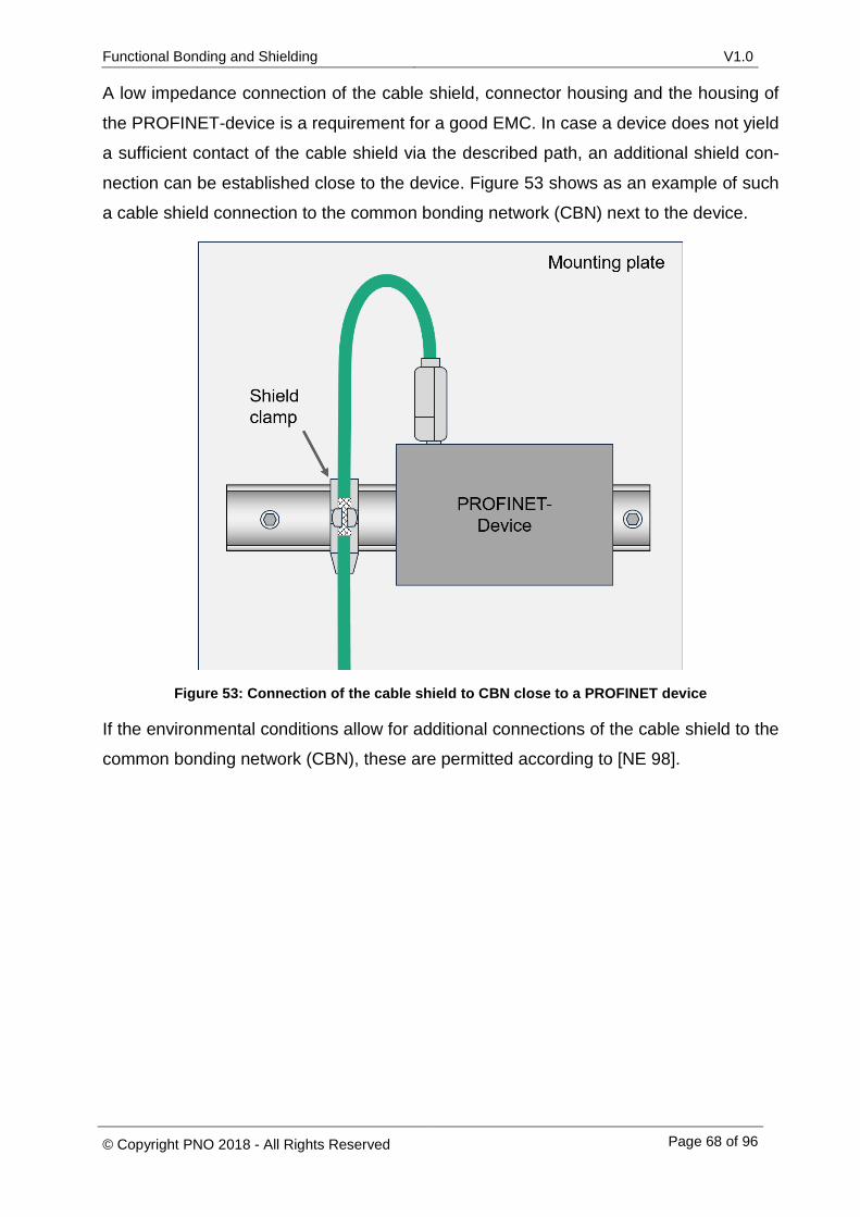
Functional Bonding and Shielding V1.0
© Copyright PNO 2018 - All Rights Reserved Page 68 of 96
A low impedance connection of the cable shield, connector housing and the housing of
the PROFINET-device is a requirement for a good EMC. In case a device does not yield
a sufficient contact of the cable shield via the described path, an additional shield con-
nection can be established close to the device. Figure 53 shows as an example of such
a cable shield connection to the common bonding network (CBN) next to the device.
Figure 53: Connection of the cable shield to CBN close to a PROFINET device
If the environmental conditions allow for additional connections of the cable shield to the
common bonding network (CBN), these are permitted according to [NE 98].
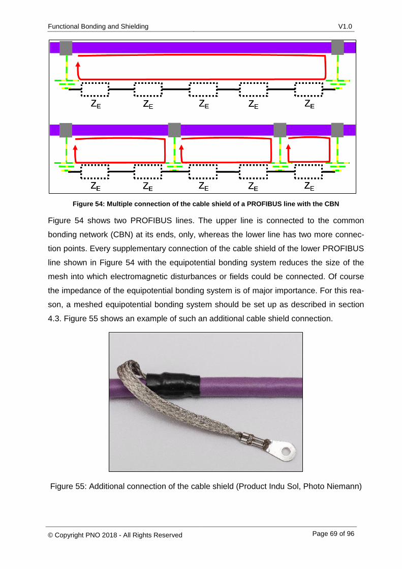
Functional Bonding and Shielding V1.0
© Copyright PNO 2018 - All Rights Reserved Page 69 of 96
Figure 54: Multiple connection of the cable shield of a PROFIBUS line with the CBN
Figure 54 shows two PROFIBUS lines. The upper line is connected to the common
bonding network (CBN) at its ends, only, whereas the lower line has two more connec-
tion points. Every supplementary connection of the cable shield of the lower PROFIBUS
line shown in Figure 54 with the equipotential bonding system reduces the size of the
mesh into which electromagnetic disturbances or fields could be connected. Of course
the impedance of the equipotential bonding system is of major importance. For this rea-
son, a meshed equipotential bonding system should be set up as described in section
4.3. Figure 55 shows an example of such an additional cable shield connection.
Figure 55: Additional connection of the cable shield (Product Indu Sol, Photo Niemann)

Functional Bonding and Shielding V1.0
© Copyright PNO 2018 - All Rights Reserved Page 70 of 96
4.4.2 Recommendations for PROFIBUS and PROFINET
For PROFINET and PROFIBUS connections, special attention should be paid to the
connector housing which should have a large contact surface for the cable shield. Addi-
tionally, the PROFIBUS and PROFINET devices should have a low-impedance connec-
tion to the CBN to be able to easily discharge disturbance currents. As already stipulat-
ed in the Installation Guidelines for Cabling and Assembly ([PRO2009] und [PRO2015-
1]) from the PROFIBUS User Organization, the PROFINET and PROFIBUS lines can
also be connected to the common bonding network (CBN) at bus nodes using respec-
tive clamps. This additional connection to the common bonding network (CBN) through
clamps may bridge high impedances from the connector plugs that may occur.
From this section of the document, the recommendation R4 is derived:
Provide a connection of the PROFIBUS/PROFINET cable shields through the
housings of the connectors and through the housings of the devices and thus
to the common bonding network (CBN) at each cable end with big contact sur-
faces (low impedance).
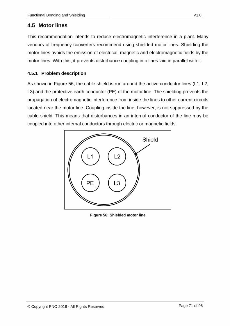
Functional Bonding and Shielding V1.0
© Copyright PNO 2018 - All Rights Reserved Page 71 of 96
4.5 Motor lines
This recommendation intends to reduce electromagnetic interference in a plant. Many
vendors of frequency converters recommend using shielded motor lines. Shielding the
motor lines avoids the emission of electrical, magnetic and electromagnetic fields by the
motor lines. With this, it prevents disturbance coupling into lines laid in parallel with it.
4.5.1 Problem description
As shown in Figure 56, the cable shield is run around the active conductor lines (L1, L2,
L3) and the protective earth conductor (PE) of the motor line. The shielding prevents the
propagation of electromagnetic interference from inside the lines to other current circuits
located near the motor line. Coupling inside the line, however, is not suppressed by the
cable shield. This means that disturbances in an internal conductor of the line may be
coupled into other internal conductors through electric or magnetic fields.
Figure 56: Shielded motor line
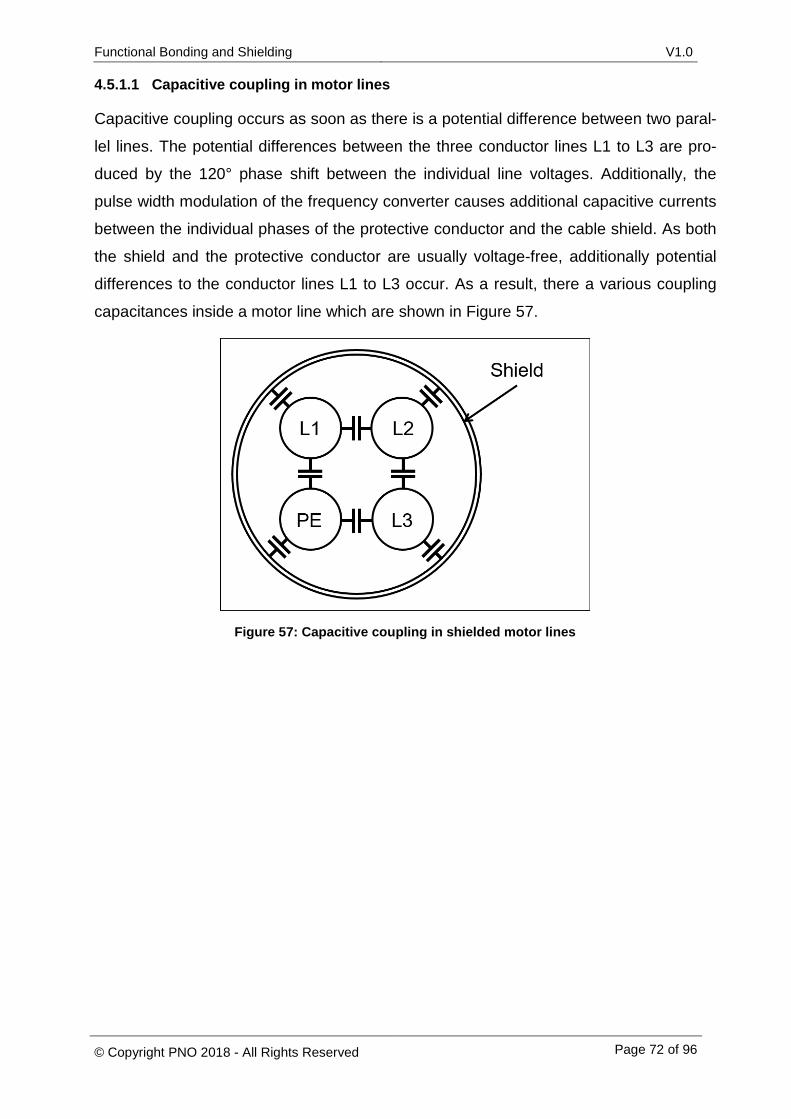
Functional Bonding and Shielding V1.0
© Copyright PNO 2018 - All Rights Reserved Page 72 of 96
4.5.1.1 Capacitive coupling in motor lines
Capacitive coupling occurs as soon as there is a potential difference between two paral-
lel lines. The potential differences between the three conductor lines L1 to L3 are pro-
duced by the 120° phase shift between the individual line voltages. Additionally, the
pulse width modulation of the frequency converter causes additional capacitive currents
between the individual phases of the protective conductor and the cable shield. As both
the shield and the protective conductor are usually voltage-free, additionally potential
differences to the conductor lines L1 to L3 occur. As a result, there a various coupling
capacitances inside a motor line which are shown in Figure 57.
Figure 57: Capacitive coupling in shielded motor lines
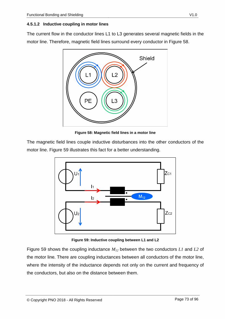
Functional Bonding and Shielding V1.0
© Copyright PNO 2018 - All Rights Reserved Page 73 of 96
4.5.1.2 Inductive coupling in motor lines
The current flow in the conductor lines L1 to L3 generates several magnetic fields in the
motor line. Therefore, magnetic field lines surround every conductor in Figure 58.
Figure 58: Magnetic field lines in a motor line
The magnetic field lines couple inductive disturbances into the other conductors of the
motor line. Figure 59 illustrates this fact for a better understanding.
Figure 59: Inductive coupling between L1 and L2
Figure 59 shows the coupling inductance M12 between the two conductors L1 and L2 of
the motor line. There are coupling inductances between all conductors of the motor line,
where the intensity of the inductance depends not only on the current and frequency of
the conductors, but also on the distance between them.
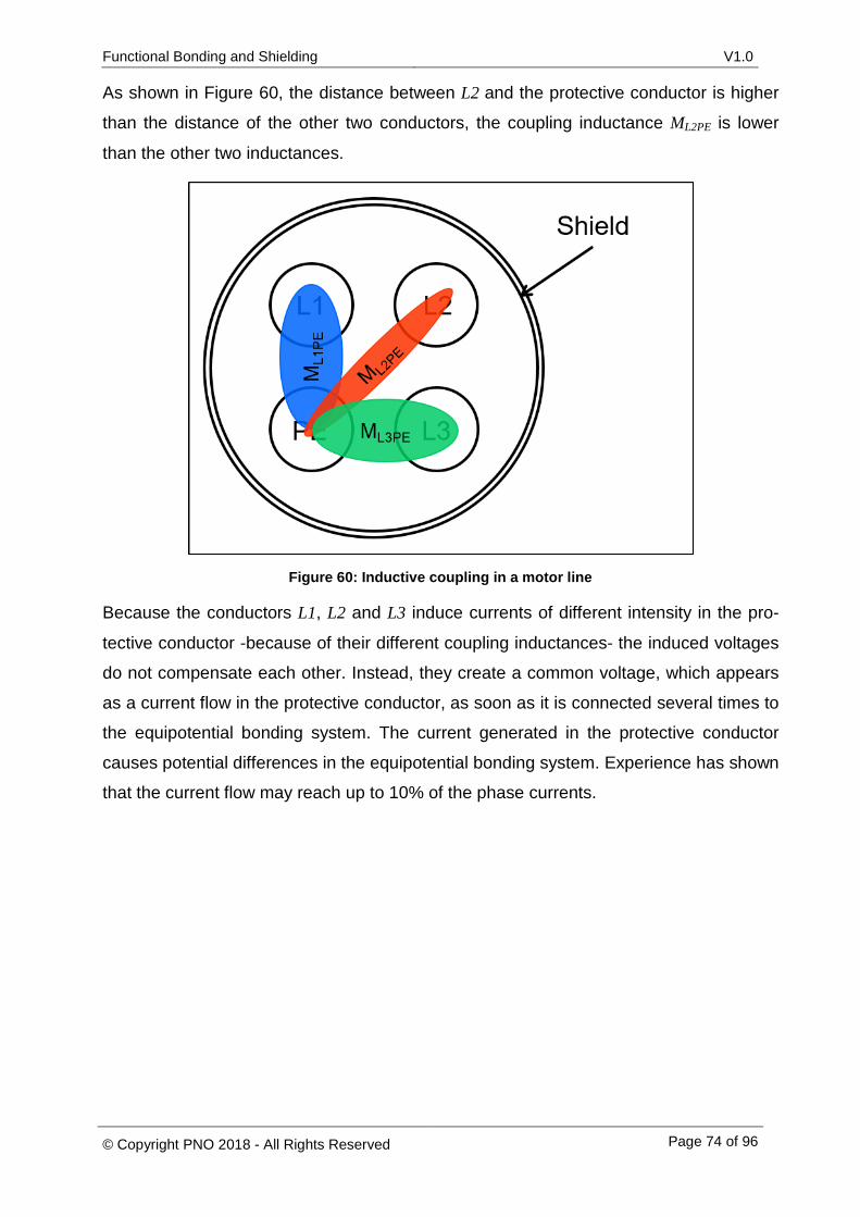
Functional Bonding and Shielding V1.0
© Copyright PNO 2018 - All Rights Reserved Page 74 of 96
As shown in Figure 60, the distance between L2 and the protective conductor is higher
than the distance of the other two conductors, the coupling inductance ML2PE is lower
than the other two inductances.
Figure 60: Inductive coupling in a motor line
Because the conductors L1, L2 and L3 induce currents of different intensity in the pro-
tective conductor -because of their different coupling inductances- the induced voltages
do not compensate each other. Instead, they create a common voltage, which appears
as a current flow in the protective conductor, as soon as it is connected several times to
the equipotential bonding system. The current generated in the protective conductor
causes potential differences in the equipotential bonding system. Experience has shown
that the current flow may reach up to 10% of the phase currents.
Functional Bonding and Shielding V1.0
© Copyright PNO 2018 - All Rights Reserved Page 75 of 96
4.5.2 Solutions from standards and specialist literature
As the motor line is an important part for CE certification, the frequency converter doc-
umentation usually specifies the cable type. This is, for example, the case in the docu-
mentation from Siemens [SIE2014], Danfoss [DAN2015], Lenze [LEN2015] and ABB
[ABB2005]. All of these four vendors prescribe shielded motor lines. However, the struc-
tures of their motor lines differ in detail. The mentioned vendors are presented here as
examples in order to allow for a better understanding. The list does not claim to be ex-
haustive. Lenze describes asymmetrical motor lines as shown in Figure 56 in its docu-
ments. ABB and Danfoss do not make any statement in their document about the type
of motor line. Figure 61 shows an excerpt from the manufacturer documentation from
Danfoss [DAN2015]. At you can see the connection line of the motor. It stands out
that a separate protective conductor (PE) is to be implemented. At the connection point
of the frequency converter, it becomes evident that the motor line has three phase
lines and one cable shield only. The motor line in the figure does not have a protective
conductor.
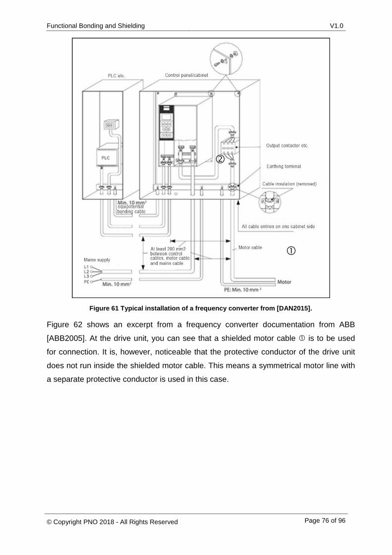
Functional Bonding and Shielding V1.0
© Copyright PNO 2018 - All Rights Reserved Page 76 of 96
Figure 61 Typical installation of a frequency converter from [DAN2015].
Figure 62 shows an excerpt from a frequency converter documentation from ABB
[ABB2005]. At the drive unit, you can see that a shielded motor cable is to be used
for connection. It is, however, noticeable that the protective conductor of the drive unit
does not run inside the shielded motor cable. This means a symmetrical motor line with
a separate protective conductor is used in this case.
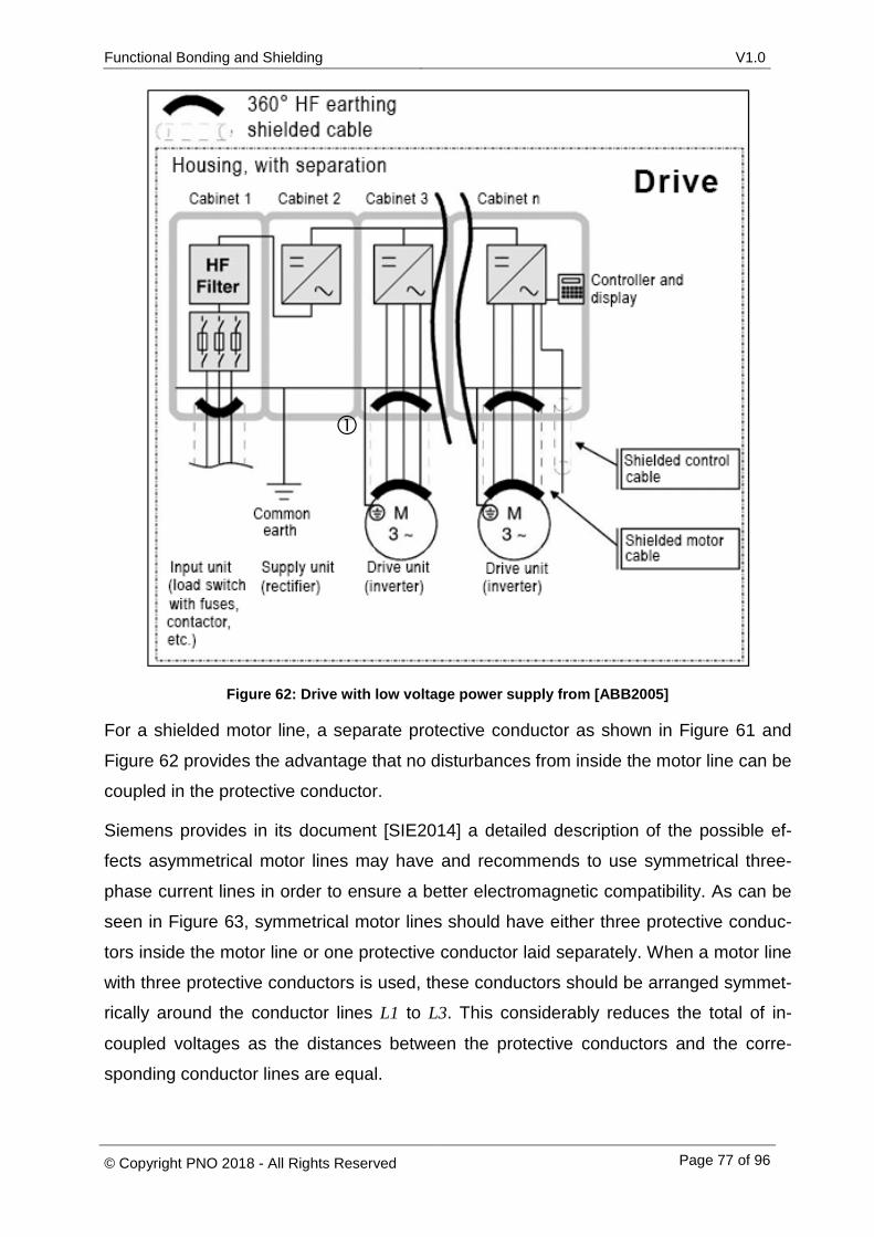
Functional Bonding and Shielding V1.0
© Copyright PNO 2018 - All Rights Reserved Page 77 of 96
Figure 62: Drive with low voltage power supply from [ABB2005]
For a shielded motor line, a separate protective conductor as shown in Figure 61 and
Figure 62 provides the advantage that no disturbances from inside the motor line can be
coupled in the protective conductor.
Siemens provides in its document [SIE2014] a detailed description of the possible ef-
fects asymmetrical motor lines may have and recommends to use symmetrical three-
phase current lines in order to ensure a better electromagnetic compatibility. As can be
seen in Figure 63, symmetrical motor lines should have either three protective conduc-
tors inside the motor line or one protective conductor laid separately. When a motor line
with three protective conductors is used, these conductors should be arranged symmet-
rically around the conductor lines L1 to L3. This considerably reduces the total of in-
coupled voltages as the distances between the protective conductors and the corre-
sponding conductor lines are equal.
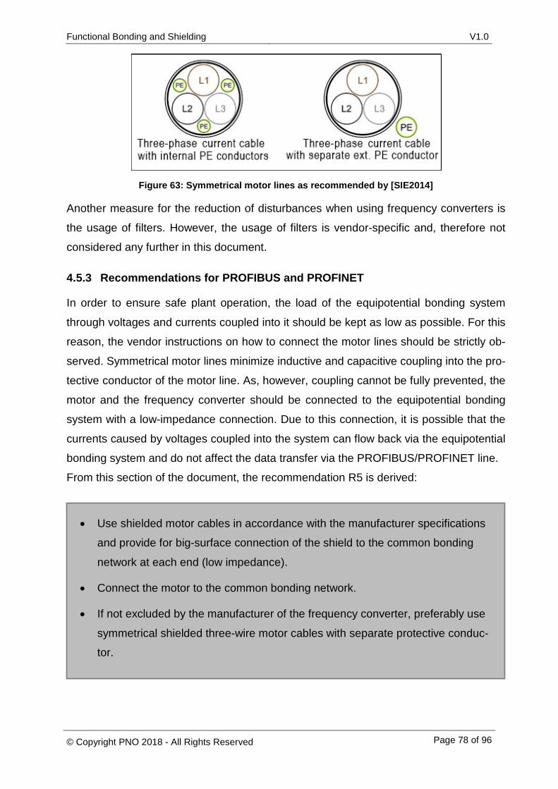
Functional Bonding and Shielding V1.0
© Copyright PNO 2018 - All Rights Reserved Page 78 of 96
Figure 63: Symmetrical motor lines as recommended by [SIE2014]
Another measure for the reduction of disturbances when using frequency converters is
the usage of filters. However, the usage of filters is vendor-specific and, therefore not
considered any further in this document.
4.5.3 Recommendations for PROFIBUS and PROFINET
In order to ensure safe plant operation, the load of the equipotential bonding system
through voltages and currents coupled into it should be kept as low as possible. For this
reason, the vendor instructions on how to connect the motor lines should be strictly ob-
served. Symmetrical motor lines minimize inductive and capacitive coupling into the pro-
tective conductor of the motor line. As, however, coupling cannot be fully prevented, the
motor and the frequency converter should be connected to the equipotential bonding
system with a low-impedance connection. Due to this connection, it is possible that the
currents caused by voltages coupled into the system can flow back via the equipotential
bonding system and do not affect the data transfer via the PROFIBUS/PROFINET line.
From this section of the document, the recommendation R5 is derived:
• Use shielded motor cables in accordance with the manufacturer specifications
and provide for big-surface connection of the shield to the common bonding
network at each end (low impedance).
• Connect the motor to the common bonding network.
• If not excluded by the manufacturer of the frequency converter, preferably use
symmetrical shielded three-wire motor cables with separate protective conduc-
tor.
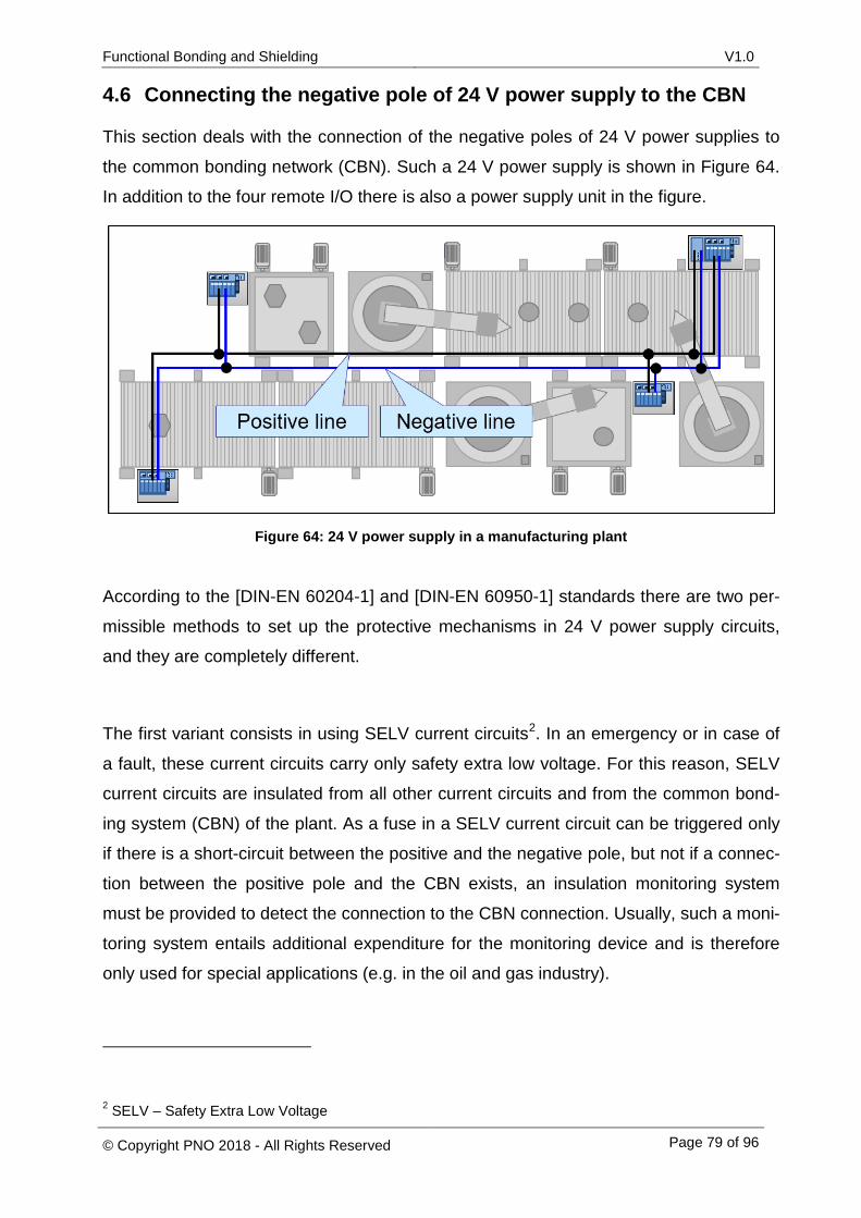
Functional Bonding and Shielding V1.0
© Copyright PNO 2018 - All Rights Reserved Page 79 of 96
4.6 Connecting the negative pole of 24 V power supply to the CBN
This section deals with the connection of the negative poles of 24 V power supplies to
the common bonding network (CBN). Such a 24 V power supply is shown in Figure 64.
In addition to the four remote I/O there is also a power supply unit in the figure.
Figure 64: 24 V power supply in a manufacturing plant
According to the [DIN-EN 60204-1] and [DIN-EN 60950-1] standards there are two per-
missible methods to set up the protective mechanisms in 24 V power supply circuits,
and they are completely different.
The first variant consists in using SELV current circuits2. In an emergency or in case of
a fault, these current circuits carry only safety extra low voltage. For this reason, SELV
current circuits are insulated from all other current circuits and from the common bond-
ing system (CBN) of the plant. As a fuse in a SELV current circuit can be triggered only
if there is a short-circuit between the positive and the negative pole, but not if a connec-
tion between the positive pole and the CBN exists, an insulation monitoring system
must be provided to detect the connection to the CBN connection. Usually, such a moni-
toring system entails additional expenditure for the monitoring device and is therefore
only used for special applications (e.g. in the oil and gas industry).
2 SELV – Safety Extra Low Voltage
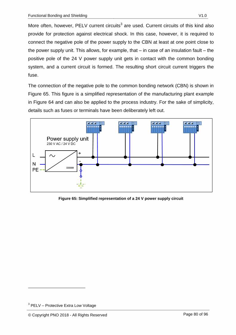
Functional Bonding and Shielding V1.0
© Copyright PNO 2018 - All Rights Reserved Page 80 of 96
More often, however, PELV current circuits3 are used. Current circuits of this kind also
provide for protection against electrical shock. In this case, however, it is required to
connect the negative pole of the power supply to the CBN at least at one point close to
the power supply unit. This allows, for example, that – in case of an insulation fault – the
positive pole of the 24 V power supply unit gets in contact with the common bonding
system, and a current circuit is formed. The resulting short circuit current triggers the
fuse.
The connection of the negative pole to the common bonding network (CBN) is shown in
Figure 65. This figure is a simplified representation of the manufacturing plant example
in Figure 64 and can also be applied to the process industry. For the sake of simplicity,
details such as fuses or terminals have been deliberately left out.
Figure 65: Simplified representation of a 24 V power supply circuit
3 PELV – Protective Extra Low Voltage
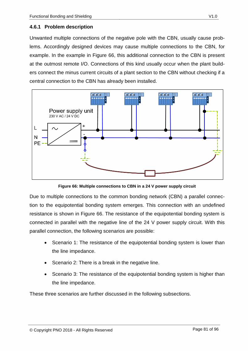
Functional Bonding and Shielding V1.0
© Copyright PNO 2018 - All Rights Reserved Page 81 of 96
4.6.1 Problem description
Unwanted multiple connections of the negative pole with the CBN, usually cause prob-
lems. Accordingly designed devices may cause multiple connections to the CBN, for
example. In the example in Figure 66, this additional connection to the CBN is present
at the outmost remote I/O. Connections of this kind usually occur when the plant build-
ers connect the minus current circuits of a plant section to the CBN without checking if a
central connection to the CBN has already been installed.
Figure 66: Multiple connections to CBN in a 24 V power supply circuit
Due to multiple connections to the common bonding network (CBN) a parallel connec-
tion to the equipotential bonding system emerges. This connection with an undefined
resistance is shown in Figure 66. The resistance of the equipotential bonding system is
connected in parallel with the negative line of the 24 V power supply circuit. With this
parallel connection, the following scenarios are possible:
• Scenario 1: The resistance of the equipotential bonding system is lower than
the line impedance.
• Scenario 2: There is a break in the negative line.
• Scenario 3: The resistance of the equipotential bonding system is higher than
the line impedance.
These three scenarios are further discussed in the following subsections.
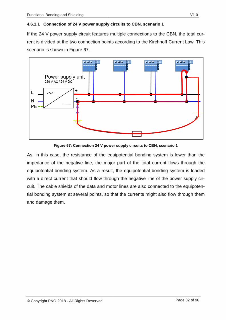
Functional Bonding and Shielding V1.0
© Copyright PNO 2018 - All Rights Reserved Page 82 of 96
4.6.1.1 Connection of 24 V power supply circuits to CBN, scenario 1
If the 24 V power supply circuit features multiple connections to the CBN, the total cur-
rent is divided at the two connection points according to the Kirchhoff Current Law. This
scenario is shown in Figure 67.
Figure 67: Connection 24 V power supply circuits to CBN, scenario 1
As, in this case, the resistance of the equipotential bonding system is lower than the
impedance of the negative line, the major part of the total current flows through the
equipotential bonding system. As a result, the equipotential bonding system is loaded
with a direct current that should flow through the negative line of the power supply cir-
cuit. The cable shields of the data and motor lines are also connected to the equipoten-
tial bonding system at several points, so that the currents might also flow through them
and damage them.
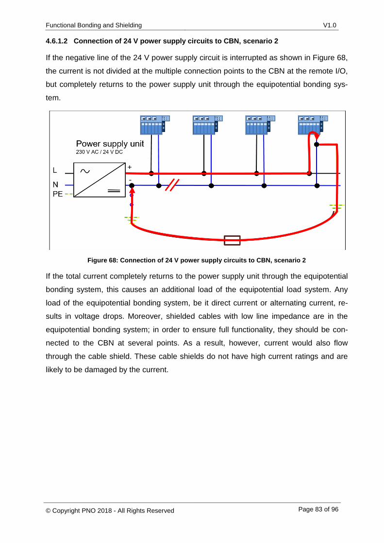
Functional Bonding and Shielding V1.0
© Copyright PNO 2018 - All Rights Reserved Page 83 of 96
4.6.1.2 Connection of 24 V power supply circuits to CBN, scenario 2
If the negative line of the 24 V power supply circuit is interrupted as shown in Figure 68,
the current is not divided at the multiple connection points to the CBN at the remote I/O,
but completely returns to the power supply unit through the equipotential bonding sys-
tem.
Figure 68: Connection of 24 V power supply circuits to CBN, scenario 2
If the total current completely returns to the power supply unit through the equipotential
bonding system, this causes an additional load of the equipotential load system. Any
load of the equipotential bonding system, be it direct current or alternating current, re-
sults in voltage drops. Moreover, shielded cables with low line impedance are in the
equipotential bonding system; in order to ensure full functionality, they should be con-
nected to the CBN at several points. As a result, however, current would also flow
through the cable shield. These cable shields do not have high current ratings and are
likely to be damaged by the current.
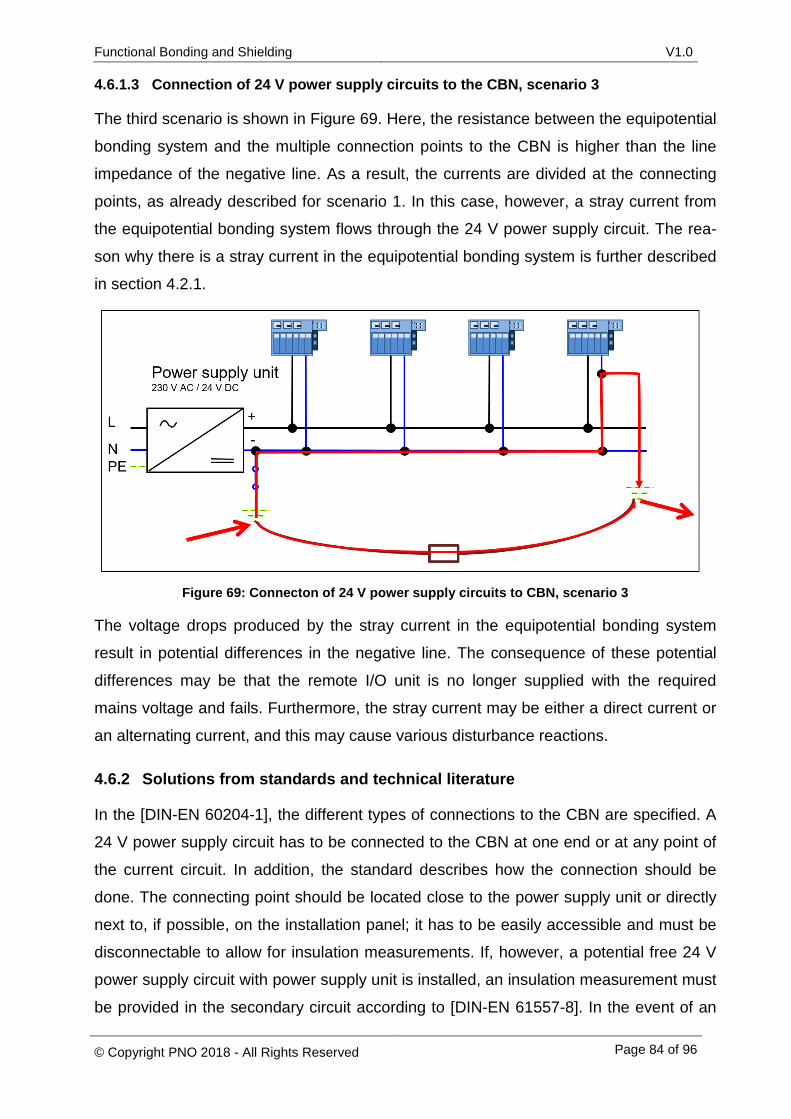
Functional Bonding and Shielding V1.0
© Copyright PNO 2018 - All Rights Reserved Page 84 of 96
4.6.1.3 Connection of 24 V power supply circuits to the CBN, scenario 3
The third scenario is shown in Figure 69. Here, the resistance between the equipotential
bonding system and the multiple connection points to the CBN is higher than the line
impedance of the negative line. As a result, the currents are divided at the connecting
points, as already described for scenario 1. In this case, however, a stray current from
the equipotential bonding system flows through the 24 V power supply circuit. The rea-
son why there is a stray current in the equipotential bonding system is further described
in section 4.2.1.
Figure 69: Connecton of 24 V power supply circuits to CBN, scenario 3
The voltage drops produced by the stray current in the equipotential bonding system
result in potential differences in the negative line. The consequence of these potential
differences may be that the remote I/O unit is no longer supplied with the required
mains voltage and fails. Furthermore, the stray current may be either a direct current or
an alternating current, and this may cause various disturbance reactions.
4.6.2 Solutions from standards and technical literature
In the [DIN-EN 60204-1], the different types of connections to the CBN are specified. A
24 V power supply circuit has to be connected to the CBN at one end or at any point of
the current circuit. In addition, the standard describes how the connection should be
done. The connecting point should be located close to the power supply unit or directly
next to, if possible, on the installation panel; it has to be easily accessible and must be
disconnectable to allow for insulation measurements. If, however, a potential free 24 V
power supply circuit with power supply unit is installed, an insulation measurement must
be provided in the secondary circuit according to [DIN-EN 61557-8]. In the event of an

Functional Bonding and Shielding V1.0
© Copyright PNO 2018 - All Rights Reserved Page 85 of 96
alarm, it may be used either for immediate disconnection or for outputting an optical
and/or acoustic signal, depending on the risk level.
4.6.3 Recommendations for PROFIBUS and PROFINET
If a PELV current circuit is chosen for 24 V power supply, it should only be connected
once to the functional equipotential bonding system/CBN directly at the power supply
unit and using a disconnect terminal. When commissioning the 24 V power supply cir-
cuit, you can perform an insulation measurement and make sure that there is no addi-
tional connection to the equipotential bonding system. However, if you discover multiple
connection points during this measurement, you will need to check if it is possible to
remove them. Multiple connection points of 24 V power supply circuits with the CBN
have to be avoided, due to the reasons described in Section 4.6.1.
Devices that have a fixed connection between functional bonding connector and the
minus of the 24 V power supply circuit, create multiple connections of the 24 V power
supply circuit with the CBN. In this case, the 24 V power supply circuit should have a
small size, to limit the impact of a multiple connections to the CBN, described in section
4.6.1. It is also recommended to limit the size of a 24 V power supply circuit to the inner
of cabinets or adjacent cabinets. A good equipotential bonding inside the cabinets and
between cabinets has to be ensured. In case, 24 V power supply circuits cover larger
distances, the effects described in section 4.6.1. have to be considered. A meshed
equipotential bonding system with low impedance, as described in section 4.3.3. can
reduce, but not eliminate, the impact of a multiple connections to the CBN.
If the multiple connections to the CBN result from internal connections inside the devic-
es that are an integral part of the devices and cannot be removed. It may be necessary
to provide a separate 24 V power supply circuit in this case. Multiple connections of 24
V power supply circuits to the CBN have to be avoided. In order to ensure that no multi-
ple connections occur throughout long plant life-cycles, additional current monitoring of
the connection to the CBN (see Figure 70) can be provided. The current monitoring
equipment should be capable of measuring both direct currents and alternating current
and of recognizing all potential operating faults that may result from possible future plant
enhancements or from the replacement of devices.
Besides the grounded operation of 24 V power supply circuits a potential free operation
is also permissible. In this case, a ground fault monitoring has to be provided.
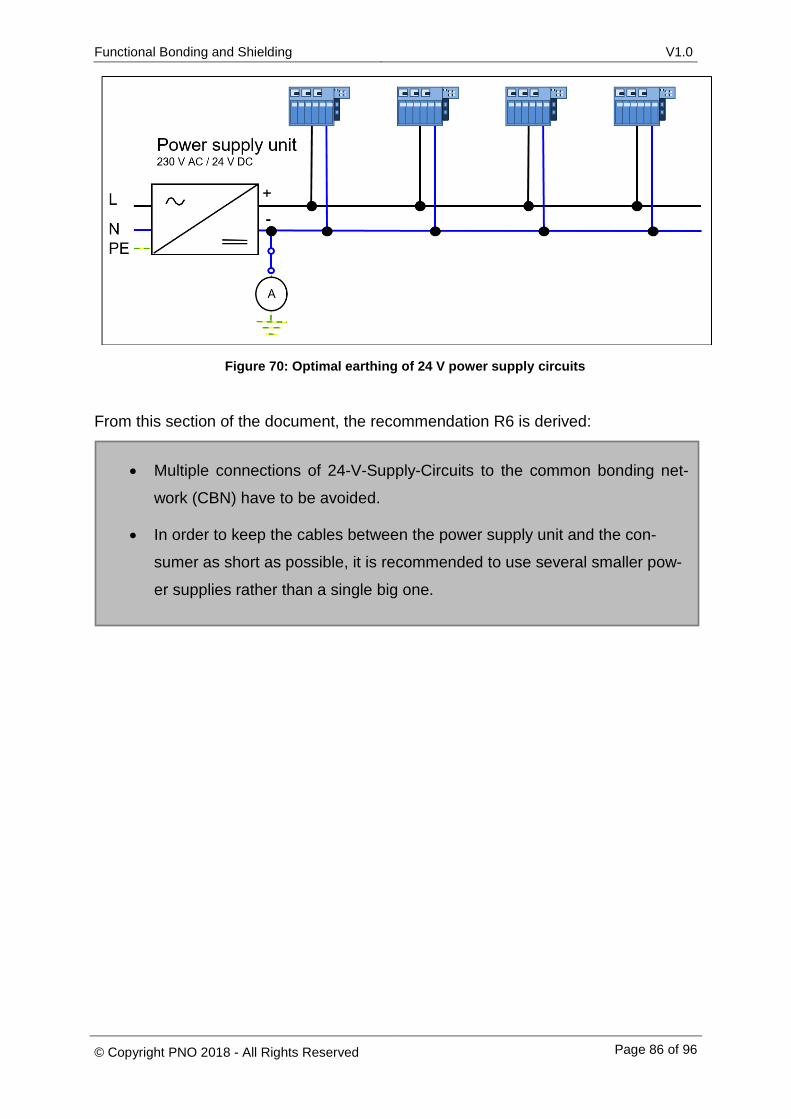
Functional Bonding and Shielding V1.0
© Copyright PNO 2018 - All Rights Reserved Page 86 of 96
Figure 70: Optimal earthing of 24 V power supply circuits
From this section of the document, the recommendation R6 is derived:
• Multiple connections of 24-V-Supply-Circuits to the common bonding net-
work (CBN) have to be avoided.
• In order to keep the cables between the power supply unit and the con-
sumer as short as possible, it is recommended to use several smaller pow-
er supplies rather than a single big one.
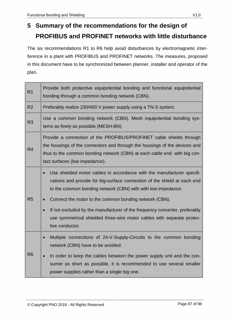
Functional Bonding and Shielding V1.0
© Copyright PNO 2018 - All Rights Reserved Page 87 of 96
5 Summary of the recommendations for the design of PROFIBUS and PROFINET networks with little disturbance
The six recommendations R1 to R6 help avoid disturbances by electromagnetic inter-
ference in a plant with PROFIBUS and PROFINET networks. The measures, proposed
in this document have to be synchronized between planner, installer and operator of the
plan.
R1 Provide both protective equipotential bonding and functional equipotential
bonding through a common bonding network (CBN).
R2 Preferably realize 230/400 V power supply using a TN-S system.
R3 Use a common bonding network (CBN). Mesh equipotential bonding sys-
tems as finely as possible (MESH-BN).
R4
Provide a connection of the PROFIBUS/PROFINET cable shields through
the housings of the connectors and through the housings of the devices and
thus to the common bonding network (CBN) at each cable end with big con-
tact surfaces (low impedance).
R5
• Use shielded motor cables in accordance with the manufacturer specifi-
cations and provide for big-surface connection of the shield at each end
to the common bonding network (CBN) with with low impedance.
• Connect the motor to the common bonding network (CBN).
• If not excluded by the manufacturer of the frequency converter, preferably
use symmetrical shielded three-wire motor cables with separate protec-
tive conductor.
R6
• Multiple connections of 24-V-Supply-Circuits to the common bonding
network (CBN) have to be avoided.
• In order to keep the cables between the power supply unit and the con-
sumer as short as possible, it is recommended to use several smaller
power supplies rather than a single big one.
Functional Bonding and Shielding V1.0
© Copyright PNO 2018 - All Rights Reserved Page 88 of 96
When planning a system, be sure to consider all recommendations if possible. Any later
plant adaptation that may become necessary in ongoing operations due to disturbances
caused by electromagnetic interference implies heavy additional expenditure.
Therefore, power supply systems in new or modernized plants should be designed as
TN-S systems only. The TN-S systems prevents operating currents from the neutral
conductor to enter the equipotential bonding system as there is only a connection be-
tween the protective conductor and the neutral conductor in the LVMD. As a result, cur-
rent flows that may cause potential differences in the equipotential bonding system are
avoided.
When implementing such a system, you can also provide for common protective and
functional equipotential bonding, as it is no longer possible to ensure consistent separa-
tion of these two equipotential bonding systems in modern plants. If a common bonding
network (CBN) is used, make sure that it meets the requirements on proper protective
and functional earthing. The equipotential bonding system must feature a sufficient am-
pacity and low impedance. For the sake of electromagnetic compatibility, the connec-
tions should be protected against unintentional loosening and adverse weather condi-
tions.
Optimal low-impedance equipotential bonding can be achieved by using a meshed
equipotential bonding system in compliance with DIN EN 50310. A meshed equipoten-
tial bonding system features a multitude of small meshes that reduce the impedance.
Low impedance reduces the occurrence of potential differences caused by coupling.
In addition, the cable shields of PROFIBUS and PROFINET lines should be connected
to the equipotential bonding system at least at both ends. The connection should be
made through the connector plug of the PROFIBUS/PROFINET device. The connection
between the connector shroud and the functional earth connector should also have a
low impedance. Additionally, there should be further connections between the cable
shields and the equipotential bonding system in order to reduce the size of the meshes
for coupling (see section 4.4.1).
Currents in the equipotential bonding system could also be caused by the motor lines.
Inside the motor lines, inductive and capacitive coupling may generate current. This can
be avoided by using shielded motor lines, which in fact are already prescribed by the
vendors of the corresponding frequency converters.

Functional Bonding and Shielding V1.0
© Copyright PNO 2018 - All Rights Reserved Page 89 of 96
When implementing 24 V power supply circuits, multiple earthing should basically be
avoided. Multiple earthing of the negative pole in a 24 V power supply circuit may allow
currents from the equipotential bonding system to reach into the 24 V power supply cir-
cuit and cause potential shifts. These potential shifts may result in the failure of units
when the voltage falls below their rated voltage. Moreover, currents from the 24 V pow-
er supply circuit may reach into the equipotential bonding system. This system, howev-
er, also comprises cable shields which do not feature a sufficiently high ampacity and
will heat with increasing current. This means that multiple earthing of a 24 V power sup-
ply circuit may present a fire hazard (see section 4.6.1.3). In order to avoid this, 24 V
power supply circuits should be earthed only once through the equipotential bonding
system. A simple monitoring function established by implementing a current monitor at
the single earthing point allows you to identify multiple earthing of the 24 V power sup-
ply circuit during ongoing plant operation.
6 Suggestions for possible acceptance tests
It is recommended, for future acceptance tests of PROFIBUS or PROFINET systems, to
also take into account their electromagnetic compatibility. To be sure, to remember the
essential points, you should use a checklist as shown in Table 2. The table has the
same layout as the checklists suggested in the Installation Guideline for Commissioning
from PROFIBUS User Organization.

Functional Bonding and Shielding V1.0
© Copyright PNO 2018 - All Rights Reserved Page 90 of 96
Table 2: Suggestions for possible acceptance tests
Plant Installation made by
Comments
EMC checklist
No. Check request YES NO Comment
1. Mains supply
1.1 Mains supply network preferably imple-mented as TN-S system?
1.2 PEN bridge provided in LVMD?
1.3 No other PEN bridges installed?
1.4 Insulation test between neutral conductor and protective conductor performed with open PEN bridge?
1.5 Current monitoring provided at PEN bridge? (optional)
No. Check request YES NO Comment
2. Equipotential bonding system
2.1 Common protective and equipotential bond-ing network (CBN) installed?
2.2 Meshed equipotential bonding system in-stalled?
2.3 Tin-plated copper strand used to ensure low impedance of the equipotential bonding system?
2.4 Is the current rating of the equipotential bonding conductor sufficient?
3. Connection of PROFIBUS/PROFINET cable shields
3.1
Is a good connection of the connector hous-ings to the housing of the PROFIBUS / PROFINET devices and thus a good con-nection to the CBN achieved?
3.2 Do the used connector plugs have suffi-ciently big contact surfaces for the cable shields?
3.3 Does the cable shield feature a low-impedance connection to the equipotential bonding system?
4. 24 V power supply circuits
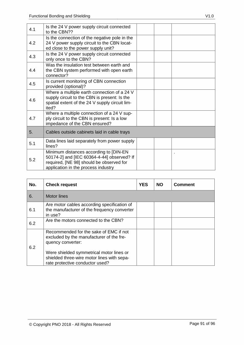
Functional Bonding and Shielding V1.0
© Copyright PNO 2018 - All Rights Reserved Page 91 of 96
4.1 Is the 24 V power supply circuit connected to the CBN??
4.2 Is the connection of the negative pole in the 24 V power supply circuit to the CBN locat-ed close to the power supply unit?
4.3 Is the 24 V power supply circuit connected only once to the CBN?
4.4 Was the insulation test between earth and the CBN system performed with open earth connector?
4.5 Is current monitoring of CBN connection provided (optional)?
4.6
Where a multiple earth connection of a 24 V supply circuit to the CBN is present: Is the spatial extent of the 24 V supply circuit lim-ited?
4.7 Where a multiple connection of a 24 V sup-ply circuit to the CBN is present: Is a low impedance of the CBN ensured?
5. Cables outside cabinets laid in cable trays
5.1 Data lines laid separately from power supply lines?
5.2
Minimum distances according to [DIN-EN 50174-2] and [IEC 60364-4-44] observed? If required, [NE 98] should be observed for application in the process industry
.
No. Check request YES NO Comment
6. Motor lines
6.1 Are motor cables according specification of the manufacturer of the frequency converter in use?
6.2 Are the motors connected to the CBN?
6.2
Recommended for the sake of EMC if not excluded by the manufacturer of the fre-quency converter: Were shielded symmetrical motor lines or shielded three-wire motor lines with sepa-rate protective conductor used?
Functional Bonding and Shielding V1.0
© Copyright PNO 2018 - All Rights Reserved Page 92 of 96
7 List of reference documents
[ABB2005] ABB: EMV gerechte Installation und Konfiguration eines Antriebs-
Systems, 2005. (EMC compliant installation and configuration of a drive sys-
tem, 2005)
[DAN2015] Fredstedt, J.: Wissenswertes über Frequenzumrichter, 2016. (Interesting
facts about frequency converters, 2016)
[DEH2016] Dehn: Erdungsfestpunkte. https://www.dehn.de/de/197/4785/Familie-
html/4785/Erdungsfestpunkte.html, 13.01.16. (Earth clips)
[DIN 18014] Deutsches Institut für Normen e. V.: Fundamenterder - Planung, Ausfüh-
rung und Dokumentation. DIN Deutsches Institut für Normung e. V., Berlin,
2014. (German Institute for Standardization: Foundation earth electrode -
Planning execution and documentation, 2014)
[DIN-EN 50174-2] Deutsches Institut für Normen e. V.: Informationstechnik -
Installation von Kommunikationsverkabelung- Teil 2: Installationsplanung und
Installationspraktiken in Gebäuden. Deutsche Kommission Elektrotechnik
Elektronik und Informationstechnik, Brüssel, 2015. (German Institute for
Standardization: Information technology - Cabling installation - Part 2: Instal-
lation planning and practices inside buildings)
[DIN-EN 50310] Deutsches Institut für Normen e. V.: Anwendung von Maßnahmen
für Erdung und Potenzialausgleich in Gebäuden mit Einrichtungen der Infor-
mationstechnik. Deutsche Kommission Elektrotechnik Elektronik und Infor-
mationstechnik, Brüssel, 2011. (German Institute for Standardization: Appli-
cation of equipotential bonding and earthing in buildings with information
technology equipment)
[DIN-EN 60204-1] Deutsches Institut für Normen e. V.: Sicherheit von Maschinen -
Elektrische Ausrüstung von Maschinen-. VDE-Verlag, Berlin, 2014. (German
Institute for Standardization: Safety of machinery - Electrical equipment of
machines - Part 1: General requirements)
[DIN-EN 60950-1] Deutsches Institut für Normen e. V.: Einrichtungen in der Informati-
onstechnik - Sicherheit - Teil 1: Allgemeine Anforderungen. VDE-Verlag, Ber-
lin, 2014. (German Institute for Standardization: Information technology
equipment - Safety - Part 1: General requirements)
Functional Bonding and Shielding V1.0
© Copyright PNO 2018 - All Rights Reserved Page 93 of 96
[DIN-EN 61557-8] Deutsches Institut für Normen e. V.: Elektrische Sicherheit in Nie-
derspannungsnetzen bis AC 1000 V und DC 1500 V. DIN Deutsches Institut
für Normung e. V. und VDE Verband der Elektrotechnik Elektronik Informati-
onstechnik e. V., Berlin, 2007. (German Institute for Standardization: Electri-
cal safety in low voltage distribution systems up to 1000 V a.c. and 1500 V
d.c. - Equipment for testing, measuring or monitoring of protective measures
- Insulation monitoring devices for IT systems)
[DIN-EN 61918] Deutsches Institut für Normen e. V.: Industrielle Kommunikations-
netze –Installation von Kommunikationsnetzen in Industrieanlagen. DIN
Deutsches Institut für Normung e. V. und VDE Verband der Elektrotechnik
Elektronik Informationstechnik e. V., Berlin, 2014. (German Institute for
Standardization: Industrial communication networks - Installation of commu-
nication networks in industrial premises)
[DIN-EN 62305-4] Deutsches Institut für Normen e. V.: Blitzschutz - Teil 4: Elektrische
und elektronische Systeme in baulichen Anlagen. DIN Deutsches Institut für
Normung e. V. und VDE Verband der Elektrotechnik Elektronik Informations-
technik e. V., Berlin, 2011. (German Institute for Standardization: Protection
against lightning - Electrical and electronic systems within structures)
[DIN-VDE 0100-100] Deutsches Institut für Normen e. V.: Errichten von Nieder-
spannungsanlagen – Teil 1: Allgemeine Grundsätze, Bestimmungen allge-
meiner Merkmale, Begriffe. DIN Deutsches Institut für Normung e. V. und
VDE Verband der Elektrotechnik Elektronik Informationstechnik e. V., Ber
[GÖH2015] Göhringer, H.-L.: Technische Strategie Sitzung 2015. Status-Bericht der
Troubleshooting Arbeitsgruppe, 2015.
[IEC 60364-4-44] Deutsches Institut für Normen e. V.: (DIN VDE 0100-444) Errichten
von Niederspannungsanlagen - Teil 4-444: Schutzmaßnahmen - Schutz bei
Störspannungen und elektromagnetischen Störgrößen (IEC 60364-4-44).
DIN Deutsches Institut für Normung e. V. und VDE Verband der Elektrotech-
nik Elektronik Informationstechnik e. V., Berlin, 2010.
(IEC 60364-4-44 Low-voltage electrical installations -. Part 4-44: Protection
for safety - Protection against voltage disturbances and electromagnetic dis-
turbances)
Functional Bonding and Shielding V1.0
© Copyright PNO 2018 - All Rights Reserved Page 94 of 96
[IEC 60364-5-54] Deutsches Institut für Normen e. V.: Errichten von Niederspan-
nungsanlagen - Teil 5-54: Auswahl und Errichtung elektrischer Betriebsmittel
- Erdungsanlagen und Schutzleiter (DIN-VDE 0100-540); Deutsche Über-
nahme HD 60364-5-54:2011. Deutsche Kommission Elektrotechnik El-
ektronik und Informationstechnik, Frankfurt am Main, 2012.
(IEC 60364-5-54: Low-voltage electrical installations - Part 5-54: Selection
and erection of electrical equipment - Earthing arrangements and protective
conductors)
[KLE2016] Kleinwächter: Elektrostatische Aufladung verstehen und sicher messen.
http://www.kleinwaechtergmbh.de/cms/upload/downloads/allgemein/ESD_An
leitung.pdf, 18.01.16.
[LEN2015] Lenze SE: Gerätehandbuch L-force Drives 9400, 2015.
[NA 114] NAMUR-Arbeitskreis 2.6 „Feldbus“ und 1.8 „Montage“: Best Practice Feld-
busanwendungen. Auswahl, Planung, Montage, Inbetriebnahmeund Betrieb
von Feldbussen, Leverkusen, 2012.
[NE 98] NAMUR-Arbeitskreis 4.6 „EMV“: EMV-gerechte Planung und Installation von
Produktionsanlagen, Leverkusen, 2007.
[NIE2017] Niemann, K.-H. Niemann, K.-H.: Produkt: Indu-Sol, Foto: Niemann. Email,
Hannover, 2017.
[PRO2009] PROFIBUS Nutzerorganisation e.V.: PROFINET Montagerichtlinie, Karls-
ruhe, 2009. (PROFINET Installation Guideline)
[PRO2015-1] PROFIBUS Nutzerorganisation e.V.: PROFIBUS. Montagerichtlinie.
http://www.profibus.com/nc/download/installation-guide/downloads/profibus-
installation-guideline/display/, 12.01.16. (PROFIBUS Installation Guideline for
Cabling and Assembly)
[RUD2011] Rudnik, S.: EMV-Fibel für Elektroniker, Elektroinstallateure und Planer.
Maßnahmen zur elektromagnetischen Verträglichkeit nach DIN VDE 0100-
444:2010-10. VDE-Verl., Berlin [u.a.], 2011.
[SCH2008] Schmolke, H.: EMV-gerechte Errichtung von Niederspannungsanlagen.
Planung und Errichtung elektrischer Anlagen nach den Normen der Gruppen
0100 und 0800 des VDE-Vorschriftenwerks. VDE-Verl., Berlin, 2008.

Functional Bonding and Shielding V1.0
© Copyright PNO 2018 - All Rights Reserved Page 95 of 96
[SIE2014] Siemens: SINAMICS - Low VoltageProjektierungshandbuch. SINAMICS
G130, G150, S120 Chassis, S120 Cabinet Modules, S150.
http://w3app.siemens.com/mcms/infocenter/dokumentencenter/ld/InfocenterL
anguagePacks/sinamics-projektierungshandbuch-lv/sinamics-
projektierungshandbuch-lv-de.pdf, 26.11.15.
[WOL2008] Wolfsperger, H. A.: Elektromagnetische Schirmung. Theorie und Praxis-
beispiele. Springer, Berlin, Heidelberg, 2008.
OL2015] Wolff, G. K.: Erdung - (K)ein Buch mit sieben Siegeln, Blomberg, 2015.

Functional Bonding and Shielding V1.0
© Copyright PNO 2018 - All Rights Reserved Page 96 of 96
Copyright by
PROFIBUS Nutzerorganisation e. V. (PNO) PROFIBUS & PROFINET International (PI) Haid-und-Neu-Str. 7 76131 Karlsruhe Germany Phone +49 721 96 58 590 Fax +49 721 96 58 589 E-mail [email protected] www.profibus.com www.profinet.com


