Optical improvement of Mo/Si multilayer reflectivemirrors for the extreme-ultraviolet (EUV) spectralrange around 13:5nm is stimulated by the progressof the next generation lithography systems for thesemiconductor industry [1]. In the past decade, themain focus of research has been increasing the peakreflectivity of mirrors, because designs for EUV litho-graphy systems should be based on at least six re-flecting surfaces [2]. The application of multilayeroptics in EUV lithography requires not only the high-est possible normal-incidence reflectivity but alsolong-term thermal and radiation stability. This re-quirement is most important in the case of the collec-tor mirror of the illumination system close to theEUV source, where a short-time decrease in reflectiv-ity is most likely [3]. The stability of Mo/Si multilayermirrors and the optics lifetime under heavy radiationloads remains one of the outstanding issues on theroad to commercialization of EUV lithography. TheEUV-induced formation of contamination layers
(carbon growth and oxidation of the top layers)and the erosion of the multilayer structure by emis-sion of high-energy ions (with kinetic energies of tensof keV in the case of xenon) are known processes thatinduce a degradation of the optical properties of Si-capped Mo/Si multilayers under exposure by EUVradiation [4–6]. The instability of Mo/Si multilayermirrors becomes especially critical at elevated pres-sures of water vapor and hydrocarbons, thus notice-ably limiting the application time of Si-capped Mo/Simultilayers [7]. To increase the lifetime of EUVmultilayer mirrors, a capping layer can be depositedon top of the structure. It must consist of a materialthat is resistant to oxidation, can be smoothly depos-ited, and is chemically inert with respect to the mul-tilayer materials (with no interdiffusion process) andwhose optical constants in the EUV spectral rangedo not lead to a drop of the peak reflectivity at thewavelength of 13:5nm [8].
The phenomenon of surface modification of Mo/Simultilayer mirrors under different EUV irradiationconditions has already been investigated by differentgroups [9–11]. In this paper, a model for the EUV-induced oxidation process is presented. A varietyof different characterization techniques is applied
to validate the assumptions and to quantify themodel parameters.
2. Experiment
Si-capped Mo/Si multilayer mirrors were designedfor a wavelength of λ ¼ 13:5nm and deposited bydc-magnetron (direct current) sputtering. Changesof optical and structural properties of samples afterEUV irradiation were characterized by small-anglex-ray reflectometry (SAXR), EUV reflectometry, andscattering measurements at 13:5nm, as well asatomic force microscopy (AFM) and x-ray photoelec-tron spectroscopy (XPS).
A. Preparation of Samples
All samples were deposited by dc-magnetron sputter-ing, using the industrial sputtering system MRC903M from Kenotec [12]. The deposition system isbased on a lateral translation of the substrate holderunder two rectangular magnetrons with a size of120mm× 360mm, corresponding to a sputter-downprocess (the material is sputtered from the targetdown to the substrate). The base pressure of the sys-tem is around 10−5 Pa and is achieved by a cryopump.The multilayer deposition is performed under an Aratmosphere of 0:1Pa.
B. EUV Source and Irradiation Setup
Samples were irradiated with a Xe-gas dischargesource (hollow-cathode Z-pinch plasma geometry)from AIXUV, pulsed at 50Hz (pulse duration of about100ns) with a pulse energy of about 0:5mJ=sr at λ ¼13:5nm ð�2%Þ [13]. The tests were carried out in anunbaked vacuum chamber at a working Xe pressureof about 0:2Pa (base pressure of 2 × 10⁻³ Pa). Si-capped Mo/Si multilayer mirrors were placed at adistance of 140mm from the source (under normalincidence) and irradiated up to 8 h, correspondingto an EUV dose DEUV ¼ 40mJ=mm2.
C. Characterization
1. EUV Reflectometry
Twodifferent instrumentationswereused tomeasurethe EUV spectral reflectivity at normal incidence andthe EUV reflectivity at 13:5nm as a function of theangle of incidence (θ–2θ measurements).The near-normal-incidence EUV reflectivity mea-
surements were performed at the Physikalisch Tech-nische Bundesanstalt (PTB) reflectometer at BESSYII (Berliner Elektronenspeicherring—Gesellschaftfür Synchrotronstrahlung mbH) in Berlin [14]. Mir-rors were measured in the wavelength range from12.5 to 14:5nm at the beamline S × 700 (using aplane grating monochromator) with a wavelength re-solution of about 0:02nm [15]. The incidence angle ofthe beam was fixed at 1:5°, and the beam spot had adiameter of about 1:5mm on the sample surface. Thereflectivity was calculated as the following:
R ¼ 2I2I1 þ I3
; ð1Þ
where I1 and I3 are the direct intensities measuredbefore and after the measurement of the reflectedbeam I2. A relative uncertainty of 0.1% is achievedfor the peak spectral reflectivity of a mirror in theEUV spectral region [15].
θ–2θ measurements of EUV reflectivity were per-formed at 13:5nm by using the instrument MERLIN(measurement of EUV reflectance and scattering),which was recently developed at the FraunhoferIOF [16]. The system is based on the EUV source de-scribed in Subsection 2.B, which was also used for theirradiation experiments. A spectral and spatial pur-ity filter system supplies a clean core beam with awavelength of 13:5nm and a spectral bandwidth of0:3nm. The illumination spot at the sample positionhas a diameter of 3mm. The sample as well as thedetector arm (EUV Si photodiodes) can be rotatedwithin the plane of incidence. The measured reflec-tivity curves are calibrated with respect to a mirroralready measured at the PTB Berlin. The relativeuncertainty of the peak reflectivity is ≤0:3%.
2. X-Ray Photoelectron Spectroscopy
XPS investigations were performed at Jenoptik LOS[17]. Reference [17] gives a quantitative analysis andinformation on the chemical nature and the state ofthe detected elements (binding energy variations ofphotoionized atoms depend on their chemical envir-onment). The peak areas can be used to determinethe composition of the materials’ surface: the spec-trum of photoelectron peaks is evaluated by integra-tion of the peaks, and the chemical composition isextracted from the peak intensities (assuming ahomogeneous mixing). For Mo/Si multilayer mirrorsthe Si2p- and Mo3d peaks are fitted by Gaussian dis-tributions, and the binding energies of the chemicalbonds are then extracted [18]. As the shape of eachpeak and the binding energy is slightly altered by thechemical state of the emitting atom, it also providesinformation about the chemical bonding.
3. Small Angle X-Ray Reflectometry
Measurement of the x-ray reflectivity is the conven-tional method used for the structural characteriza-tion of EUV multilayer mirrors. All samples weremeasured with an x-ray diffractometer D 5005 fromthe firm Bruker AXS at λ1:154nm (Cu-αK radiation)with a θ–2θ geometry. In the case of multilayer sys-tems, Bragg peaks are obtained from the interferenceof the waves reflected at each interface. The periodthickness d of the multilayers can be calculated fromtheir frequencies [19]:
where θm is the grazing angle corresponding to themth maximum and θc is the critical angle for totalexternal reflection. The x-ray reflection of multilayerstructures provides information about the layer
thickness, the layer density, and the layer roughness(interdiffusion and top roughness) [20,21]. All x-rayreflection measurements were fitted by using thecommercial software REFSIM [22].
4. Atomic Force Microscopy
The surface microtopographies of the samples weremeasured by using an atomic force microscope VeecoDimension DI 3100. Single crystalline Si tips with anominal radius of 10nm were used, and the mea-surements were performed in tapping mode. Scanareas of 1 μm × 1 μm were investigated, and the high
spatial frequency roughness between 1 and 256 μm−1
was calculated from the topographic data [23].
5. EUV Scattering
The EUV scattering was measured by using the in-strument MERLIN described in Subsection 2.C.1.The samples were first illuminated at an angle of in-cidence of 1:5°. The detector was scanned in the back-scattering hemisphere between θs ¼ −30 and þ30°,where θs denotes the scatter angle measured with re-spect to the surface normal. The measured powerwas normalized to the incident power and to thedetector solid angle to obtain the angle resolved scat-tering (ARS). The total backscattering, TSb, was de-termined from ARS by numerical integration [24]:
TSb ¼ 2πZ
85°
2°ARSðθsÞ sin θsdθs: ð3Þ
The relative measurement uncertainties of both ARSand TS as a result of the possible errors of calibrationand detector linearity, as well as detector noise, arebelow 15%.
In addition, ARS measurements were performedwith the sample illuminated near the critical angleof total external reflection. Because of the lower pe-netration depth, this strategy enables a sensitivecharacterization of the top-surface roughness.
Fig. 1. Evolution of the EUV properties of Si-cappedMo/Si multi-layer mirrors after irradiation with doses up to 40mJ=mm2.
Fig. 2. Evolution of the XPS spectra of Si-capped Mo/Si multilayer mirrors after irradiation with DEUV ¼ 40mJ=mm2.
The Si-capped Mo/Si multilayers mirrors were irra-diated without any debris mitigation system (no Zrfilter) at normal incidence with the following EUVdoses: DEUV ¼ 5; 10; 20; 40mJ=mm2.The evolution of the EUV properties of the mirrors
irradiated with increasing EUV doses is presented inFig. 1. Optimized as-deposited Mo/Si multilayershave a peak reflectivity R ¼ 68:4% at λ ¼ 13:44nm.The irradiation with an EUV dose of 40mJ=mm2 in-duces a drop of reflectivity of 18.4% (R ¼ 50:0% atλ ¼ 13:44nm). As there is no modification of theshape of the peak reflectivity (the FWHM remainsstable after irradiation), the degradation processesis confined to the top layers of the multilayers.To investigate the EUV-induced modification of
the top surface, XPS studies have been performed.The evolution of the XPS spectra of Mo/Si multilayermirrors between the as-deposited state and after ir-radiation (DEUV ¼ 40mJ=mm2) for the O1, C1,Mo3d,and Si2p peaks is presented in Fig. 2. The variationof the peak intensity, found for the O1 and C1 peaks,corresponds to changes in the O and C concentra-tions in the top layers. The modifications of the peakshape (peak intensity and peak position) in the caseof the Si2p and Mo3d peaks demonstrate changes inthe Si and Mo concentrations but also in the bindingstates of each compound, mainly induced by the oxi-dation of the materials. The fit of the spectra revealsa total oxidation of the Si top layer and a partial oxi-dation of the Mo sublayer after irradiation with anEUV dose of 40mJ=mm2 (Tables 1 and 2). In theas-deposited state, only one third of the Si top layeris oxidized (SiOx), and the whole Mo sublayer is inthe metal state (Mo). After irradiation, the wholeSi top layer is oxidized (SiOx), and three quartersof the Mo sublayer is in the oxide state (MoOx).This increase in the oxidation level of the top
layers has a double impact on the reflectivity ofthe irradiated multilayer mirrors. (i) The oxidationof the Si andMo top layers causes changes of the phy-sical thicknesses of the top layers (the oxidation pro-cess is accompanied by a variation of volume),resulting in an increase of the absorption. (ii) Thepresence of more O atoms also leads to a further in-crease of the absorption of the light by the oxidizedlayers. Considering one-dimensional volume changesin the Mo/Si multilayer mirrors on oxidation of the
top layers, the full oxidation of the Si top layer in-duces an increase in the thickness of the Si-basedlayer (the Mo-based layer as well becomes thickerthrough the oxidation of the Mo sublayer). Assumingthat the molar volumes of Si and SiO2 are, respec-tively, VSi ¼ 12:1 cm3=mol and VSiO2
¼ 23:6 cm3=mol,the thickness of the SiO2 layer obtained after thetotal oxidation of the Si layer is
tSiO2¼ VSiO2
VSitSi ≈ 1:95 tSi: ð4Þ
The same calculation for the Mo sublayer (VMo ¼9:4 cm3=mol and VMoO2
¼ 19:7 cm3=mol) leads tothe following relationship:
tMoO2¼ VMoO2
VMotMo ≈ 2:1 tMo: ð5Þ
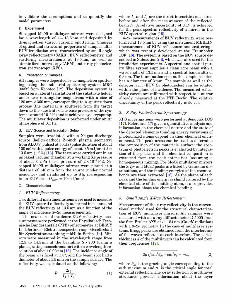
According to the previous calculations, a model forthe degradation process of the Mo/Si multilayer mir-rors under EUV radiation can be suggested (Fig. 3)
Table 1. Chemical Composition of Sample Top Layers (at. %)
State C O Si Mo
As deposited 22.2 40.3 34.7 2.2Irradiated 12.1 56.6 28.2 2.2
Table 2. Result of the Fit of Si2p and Mo3d Peaks (%)
State Si SiOx Mo MoOx
As deposited 63.6 36.4 100 0Irradiated 0 100 22.8 77.2
Fig. 3. Model of degradation of the Mo/Si multilayer mirrors un-der EUV radiation.
Fig. 4. Measured and fitted EUV reflectivity curves of aSi-capped Mo/Si multilayer mirror irradiated with DEUV ¼40mJ=mm2.
[25]. A natural oxidation of the Si top layer first hap-pens after the deposition of the mirrors. This layerhas a thickness of about 2nm. After irradiation ofthe mirrors with an EUV dose of 40mJ=mm2, a fulloxidation of the Si top layer and an oxidation of threequarters of theMo sublayer were found. On oxidationof the top layers, the total thickness of the last twolayers increases by a factor two [Eqs. (4) and (5)].It has to be noted that Fig. 3 shows the applicationof this model for a maximal EUV dose of 40mJ=mm2.A greater dose should induce a more important oxi-dation process, not limited to only the first two layersbut leading to the oxidation of a few additional layersand therefore to a larger drop of reflectivity.This model has been also used to fit the EUV re-
flectivity curve measured after the irradiation withDEUV ¼ 40mJ=mm2, obtained with the softwareIMD (Fig. 4) [26]. The fitting results show a goodagreement with the model previously proposed, de-monstrating an oxidation of the first two layers ofthe structure (total oxidation of the Si layer and par-tial oxidation for the Mo layer). It also exhibits anincrease in the top roughness up to 0:50nm.The results of the θ–2θ measurements performed
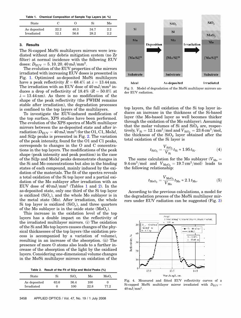
at 13:5nm are shown in Fig. 5. The peaks at 0° cor-respond to the normal-incidence reflectivity at13:5nm and clearly express the degradation of themirror reflectance induced by the irradiation. Theabsolute values of 66.9% and 48.4% for the samplesbefore and after exposition to 40mJ=mm2, respec-tively, are in good agreement with the correspondingvalues of 67.2% and 49.0% obtained from the spectralreflectivity curves at 13:5nm. The slight deviationis presumably a result of sample inhomogeneityand calibration errors.
A strong effect of the mirror degradation on theθ–2θ curve can be observed. Theoretical θ–2θ curveswere fitted to the measurement results by using IMDwith the model previously introduced. The slight de-viations between the measurement and the simula-tion results are due to the rather simple model usedfor the calculations. The results of the fit are pre-sented in Table 3. The uncertainty of the values isapproximately 1–2nm because of the large numberof fitting parameters and the simplicity of the model.
The comparison of the SAXR curves (Fig. 6) for Si-capped Mo/Si multilayer mirrors measured in the as-deposited state and after irradiation with DEUV ¼40mJ=mm2 shows no modification in the positionof the Bragg peaks, but only changes in the valleysbetween the peaks. There is therefore no change ofthe multilayer period thickness, and all changes oc-cur in the first top layers (modification of the topstructure) as already demonstrated with the analysisof the EUV reflectivity curves. The simulation of thefirst Bragg peaks (up to a grazing angle of 2°) is alsopresented in Fig. 6, which corresponds to the part ofthe curve that is the most dependent on the surfaceeffects and therefore provides information about themodification of the top layers. The results of the si-mulation achieved after irradiation with an EUVdose of 40mJ=mm2 show a full oxidation of the first
Fig. 5. Results and fit of the θ–2θ measurements.
Table 3. Thickness (nm) of Top Layers Obtained from the Fit ofθ–2θ Measurements at 13:5 nm
State Mo MoO2 Si SiO2
As deposited 2.1 0 4.0 1.0Irradiated 0.7 1.4 0.0 9.5
Fig. 6. Top, comparison of the SAXR curves for Si-capped Mo/Simultilayer mirrors as deposited and irradiated with DEUV ¼40mJ=mm2. Bottom, simulation of the first Bragg peaks afterDEUV ¼ 40mJ=mm2.
Si layers and a partial oxidation of the Mo sublayer.A development of roughness on top of the mirrors hasalso been found from 0.30 to 0:60nm with the forma-tion of a SiO2 layer on top of the multilayer structure.The high spatial frequency roughness measured by
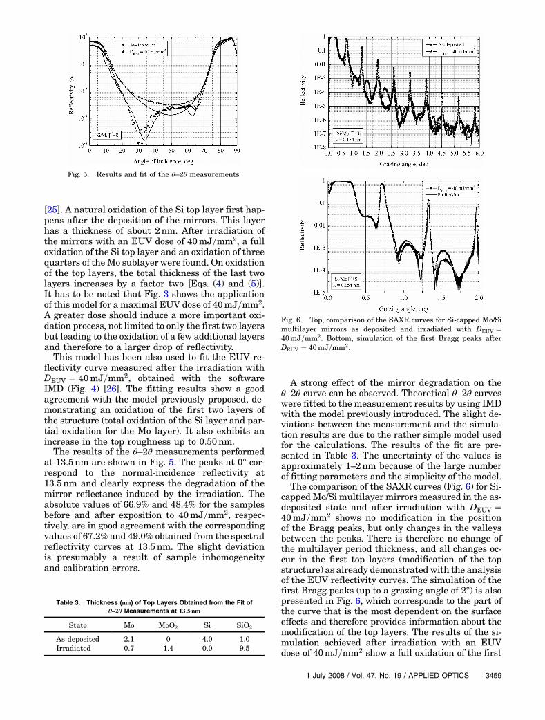
AFM (Fig. 7) increased from 0:14nm for the as-deposited state to 0:49nm for the mirrors irradiatedwith DEUV ¼ 40mJ=mm2. This is in good agreementwith the values determined by the simulation ofthe SAXR measurements, considering the differentbandwidth limits of the two methods.The power spectral densities (PSDs), defined as the
squaredmodulus of theFourier transformof the inter-face profile and calculated from the AFM data revealthat the roughness enhancement after irradiation isconcentrated around 20 μm−1 (Fig. 8). The surfacemorphology is most likely a result of roughening dur-ing the formation of the oxide layer as well as of thinfilm erosion induced by source debris.The results of the ARSmeasurements at quasi nor-
mal incidence at 13:5nm reveal lower scatter levelsof the irradiated coating (Fig. 9). TS values of 0.9%and 0.5% were determined from the ARS data forthe as-deposited coating and the coating irradiated
with the maximum dose, respectively. This at firstglance surprising observation indicates that theroughness enhancement is confined to the upper-most layer, which only contributes a small part tothe total scattered power. The scattering from theburied interfaces that dominate the total scatteringis reduced as a result of increased absorption in theoxidized layers.
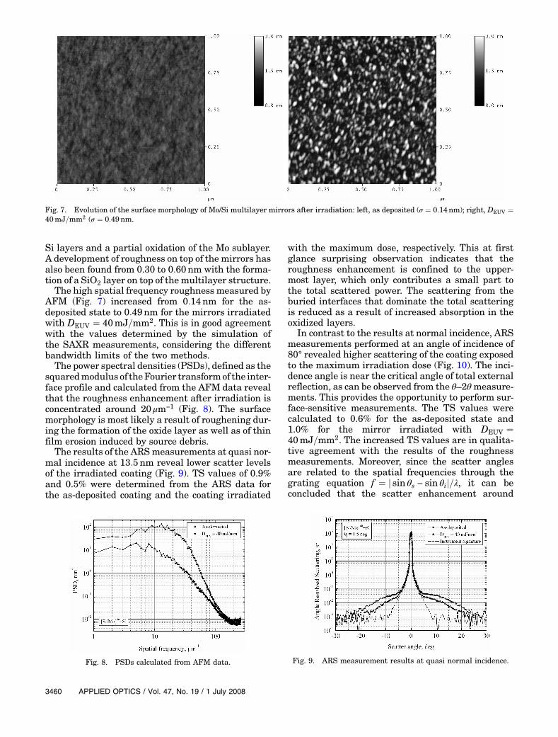
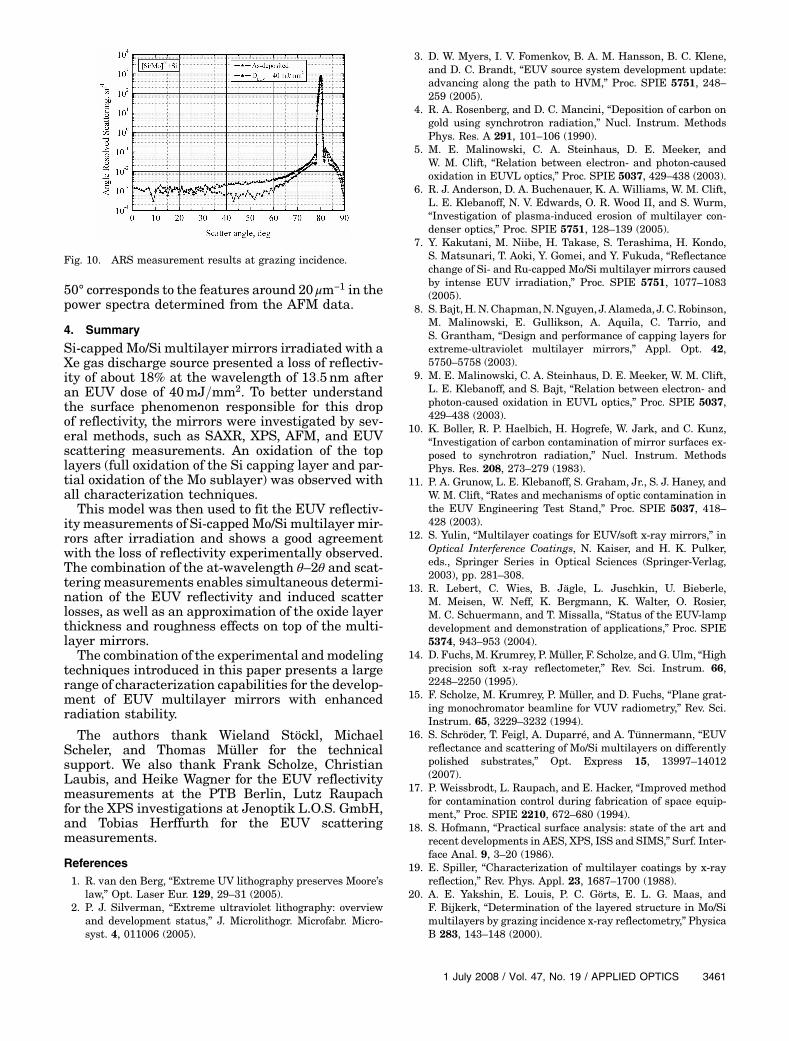
In contrast to the results at normal incidence, ARSmeasurements performed at an angle of incidence of80° revealed higher scattering of the coating exposedto the maximum irradiation dose (Fig. 10). The inci-dence angle is near the critical angle of total externalreflection, as can be observed from the θ–2θmeasure-ments. This provides the opportunity to perform sur-face-sensitive measurements. The TS values werecalculated to 0.6% for the as-deposited state and1.0% for the mirror irradiated with DEUV ¼40mJ=mm2. The increased TS values are in qualita-tive agreement with the results of the roughnessmeasurements. Moreover, since the scatter anglesare related to the spatial frequencies through thegrating equation f ¼ j sin θs − sin θij=λ, it can beconcluded that the scatter enhancement around
Fig. 7. Evolution of the surface morphology of Mo/Si multilayer mirrors after irradiation: left, as deposited (σ ¼ 0:14nm); right, DEUV ¼40mJ=mm2 (σ ¼ 0:49nm.
Fig. 8. PSDs calculated from AFM data. Fig. 9. ARS measurement results at quasi normal incidence.
50° corresponds to the features around 20 μm−1 in thepower spectra determined from the AFM data.
4. Summary
Si-capped Mo/Si multilayer mirrors irradiated with aXe gas discharge source presented a loss of reflectiv-ity of about 18% at the wavelength of 13:5nm afteran EUV dose of 40mJ=mm2. To better understandthe surface phenomenon responsible for this dropof reflectivity, the mirrors were investigated by sev-eral methods, such as SAXR, XPS, AFM, and EUVscattering measurements. An oxidation of the toplayers (full oxidation of the Si capping layer and par-tial oxidation of the Mo sublayer) was observed withall characterization techniques.This model was then used to fit the EUV reflectiv-
ity measurements of Si-cappedMo/Si multilayer mir-rors after irradiation and shows a good agreementwith the loss of reflectivity experimentally observed.The combination of the at-wavelength θ–2θ and scat-tering measurements enables simultaneous determi-nation of the EUV reflectivity and induced scatterlosses, as well as an approximation of the oxide layerthickness and roughness effects on top of the multi-layer mirrors.The combination of the experimental andmodeling
techniques introduced in this paper presents a largerange of characterization capabilities for the develop-ment of EUV multilayer mirrors with enhancedradiation stability.
The authors thank Wieland Stöckl, MichaelScheler, and Thomas Müller for the technicalsupport. We also thank Frank Scholze, ChristianLaubis, and Heike Wagner for the EUV reflectivitymeasurements at the PTB Berlin, Lutz Raupachfor the XPS investigations at Jenoptik L.O.S. GmbH,and Tobias Herffurth for the EUV scatteringmeasurements.
References1. R. van den Berg, “Extreme UV lithography preserves Moore’s
law,” Opt. Laser Eur. 129, 29–31 (2005).2. P. J. Silverman, “Extreme ultraviolet lithography: overview
and development status,” J. Microlithogr. Microfabr. Micro-syst. 4, 011006 (2005).
3. D. W. Myers, I. V. Fomenkov, B. A. M. Hansson, B. C. Klene,and D. C. Brandt, “EUV source system development update:advancing along the path to HVM,” Proc. SPIE 5751, 248–259 (2005).
4. R. A. Rosenberg, and D. C. Mancini, “Deposition of carbon ongold using synchrotron radiation,” Nucl. Instrum. MethodsPhys. Res. A 291, 101–106 (1990).
5. M. E. Malinowski, C. A. Steinhaus, D. E. Meeker, andW. M. Clift, “Relation between electron- and photon-causedoxidation in EUVL optics,” Proc. SPIE 5037, 429–438 (2003).
6. R. J. Anderson, D. A. Buchenauer, K. A. Williams, W. M. Clift,L. E. Klebanoff, N. V. Edwards, O. R. Wood II, and S. Wurm,“Investigation of plasma-induced erosion of multilayer con-denser optics,” Proc. SPIE 5751, 128–139 (2005).
7. Y. Kakutani, M. Niibe, H. Takase, S. Terashima, H. Kondo,S. Matsunari, T. Aoki, Y. Gomei, and Y. Fukuda, “Reflectancechange of Si- and Ru-capped Mo/Si multilayer mirrors causedby intense EUV irradiation,” Proc. SPIE 5751, 1077–1083(2005).
8. S. Bajt,H.N.Chapman,N.Nguyen, J. Alameda, J. C. Robinson,M. Malinowski, E. Gullikson, A. Aquila, C. Tarrio, andS. Grantham, “Design and performance of capping layers forextreme-ultraviolet multilayer mirrors,” Appl. Opt. 42,5750–5758 (2003).
9. M. E. Malinowski, C. A. Steinhaus, D. E. Meeker, W. M. Clift,L. E. Klebanoff, and S. Bajt, “Relation between electron- andphoton-caused oxidation in EUVL optics,” Proc. SPIE 5037,429–438 (2003).
10. K. Boller, R. P. Haelbich, H. Hogrefe, W. Jark, and C. Kunz,“Investigation of carbon contamination of mirror surfaces ex-posed to synchrotron radiation,” Nucl. Instrum. MethodsPhys. Res. 208, 273–279 (1983).
11. P. A. Grunow, L. E. Klebanoff, S. Graham, Jr., S. J. Haney, andW. M. Clift, “Rates and mechanisms of optic contamination inthe EUV Engineering Test Stand,” Proc. SPIE 5037, 418–428 (2003).
12. S. Yulin, “Multilayer coatings for EUV/soft x-ray mirrors,” inOptical Interference Coatings, N. Kaiser, and H. K. Pulker,eds., Springer Series in Optical Sciences (Springer-Verlag,2003), pp. 281–308.
13. R. Lebert, C. Wies, B. Jägle, L. Juschkin, U. Bieberle,M. Meisen, W. Neff, K. Bergmann, K. Walter, O. Rosier,M. C. Schuermann, and T. Missalla, “Status of the EUV-lampdevelopment and demonstration of applications,” Proc. SPIE5374, 943–953 (2004).
14. D. Fuchs, M. Krumrey, P. Müller, F. Scholze, and G. Ulm, “Highprecision soft x-ray reflectometer,” Rev. Sci. Instrum. 66,2248–2250 (1995).
15. F. Scholze, M. Krumrey, P. Müller, and D. Fuchs, “Plane grat-ing monochromator beamline for VUV radiometry,” Rev. Sci.Instrum. 65, 3229–3232 (1994).
16. S. Schröder, T. Feigl, A. Duparré, and A. Tünnermann, “EUVreflectance and scattering of Mo/Si multilayers on differentlypolished substrates,” Opt. Express 15, 13997–14012(2007).
17. P. Weissbrodt, L. Raupach, and E. Hacker, “Improved methodfor contamination control during fabrication of space equip-ment,” Proc. SPIE 2210, 672–680 (1994).
18. S. Hofmann, “Practical surface analysis: state of the art andrecent developments in AES, XPS, ISS and SIMS,” Surf. Inter-face Anal. 9, 3–20 (1986).
19. E. Spiller, “Characterization of multilayer coatings by x-rayreflection,” Rev. Phys. Appl. 23, 1687–1700 (1988).
20. A. E. Yakshin, E. Louis, P. C. Görts, E. L. G. Maas, andF. Bijkerk, “Determination of the layered structure in Mo/Simultilayers by grazing incidence x-ray reflectometry,” PhysicaB 283, 143–148 (2000).
Fig. 10. ARS measurement results at grazing incidence.
21. W. E. Wallace, and W. L. Wu, “A novel method for determiningthin film density by energy-dispersive x-ray reflectivity,” Appl.Phys. Lett. 67, 1203–1205 (1995).
22. S. Grassl and D. Fuchs, Reflectivity software WIN-REFSIM,Bruker Analytical X-ray Systems, Inc., Karlsruhe, Germany,1992–1995.
23. A. Duparré and J. Ferré-Borrull, S. Gliech, G. Notni,J. Steinert, and J. M. Bennett, “Surface characterization tech-niques for determining the root-mean-square roughness and
power spectral densities of optical components,” Appl. Opt.41, 154–171 (2002).
24. A. Duparré, “Scattering from surfaces and thin films,” in En-cyclopedia of Modern Optics, B. D. Guenther and D. G. Steel,eds. (Elsevier, 2004), pp. 314–321.
25. N. Benoit, “Radiation stability of EUV multilayer mirrors,”Ph.D. dissertation (Friedrich-Schiller-Universität Jena, 2007).
26. D. L. Windt, “IMD—software for modeling the optical proper-ties of multilayer,” Comput. Phys. 12, 360–370 (1998).