Einbauanleitung: Elektroanlage für Anhängevorrichtung
Allgemeine Daten
Artikelnummer
WESTFALIA S.I.A.R.R – No.
Fahrzeug
307 260 300 107 8884 Ford Transit Kasten / Kombi ab 04/00
307 260 300 113 -- Ford Transit Kasten / Kombi ab 04/00
Dauerplus-Erweiterungssatz für die 13-polige Steckdose
Hinweis Der Dauerplus-Erweiterungssatz ermöglicht die Inbetriebnahme einer Dauerstromversorgung und einer Ladeleitung für eine Zusatzbatterie.
Artikelnummer
Westfalia Fahrzeughersteller
Fahrzeug
300 025 300 113 - - alle Fahrzeuge
4 307 260 391 101 - 005 – 41/09 Ford Transit
Wichtige Hinweise
Vor Arbeitsbeginn die Einbauanleitung lesen.
Der Elektroeinbausatz darf nur von qualifiziertem Fachpersonal eingebaut werden.
Vorsicht - Batterie abklemmen! Beschädigung der KFZ-Elektronik, elektronisch gespeicherte Daten können verloren gehen.
Vor Arbeitsbeginn den Fehlerspeicher auslesen.
Vor dem Bohren sicherstellen, dass sich keine Gegenstände, wie z. B. Leitungen, hinter den Verkleidungen befinden.
Blanke Karosseriestellen, wie z. B. gebohrte Löcher, entgraten und anschließend mit einem Rostschutzmittel versiegeln.
Hinweis Bei der Montage auf folgende Punkte besonders achten:
• Leitungen dürfen weder eingeklemmt noch beschädigt sein.
• Alle Dichtungselemente ordnungsgemäß anbringen.
• Leitungen so verlegen, dass diese weder am Fahrzeug scheuern noch abknicken.
• Leitungen nicht in unmittelbarer Nähe der Abgasanlage verlegen.
Bei Anhängerbetrieb wird die Nebelschlussleuchte des Zugfahrzeugs abgeschaltet.
Bei Anhängern ohne Nebelschlussleuchte muss diese nachgerüstet werden.
Der Ausfall einer Blinkleuchte, auch am Anhänger, wird durch die Erhöhung der Blinkfrequenz angezeigt. Es ist keine zusätzliche Blinkkontrolle notwendig.
Ein Steckdosenadapter darf nur im Anhängerbetrieb genutzt werden. Nach dem Anhängerbetrieb den Steckdosenadapter entfernen.
Die Prüfung der Anhängerfunktionen mit einem Anhänger oder einem Prüfgerät mit Belastungswiderständen durchführen.
Technische Änderungen vorbehalten!
Ford Transit 307 260 391 101 – 005 – 41/09 5
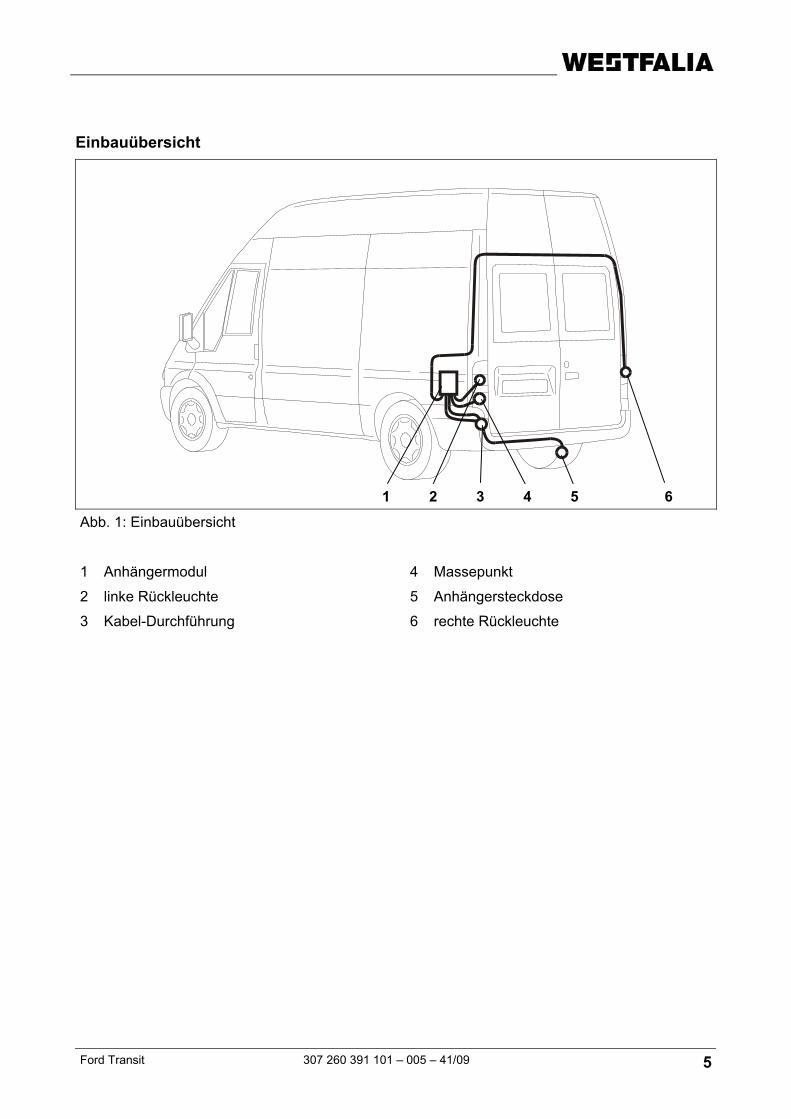
Einbauübersicht
Abb. 1: Einbauübersicht
1 Anhängermodul 4 Massepunkt
2 linke Rückleuchte 5 Anhängersteckdose
3 Kabel-Durchführung 6 rechte Rückleuchte
1 2 3 4 5 6
6 307 260 391 101 - 005 – 41/09 Ford Transit
Elektroeinbausatz einbauen
1. Minusklemme der Batterie abklemmen.
2. Reserverad entnehmen.
3. Rechte und linke Rückleuchte ausbauen.
4. Folgende Abdeckungen und Verkleidungen ggf. entfernen:
- linke hintere Seitenverkleidung im Kofferraum
- äußere Eckabdeckung unter der linken Rückleuchte
5. An der linken unteren Fahrzeugecke, an geeigneter Stelle ein Loch Ø 40 mm für die Kabel-Durchführung (Abb. 1/3) einbringen.
6. Das Leitungsende mit der Steckdose und die lange rote Einzelleitung durch die Kabel-Durchführung (Abb. 1/3), ausgehend vom Kofferraum, nach außen zum Steckdosenhalteblech (Abb. 1/5) verlegen.
7. Die Gummitülle auf den Leitungsstrang aufschieben.
8. Die Gummitülle in die Kabel-Durchführung (Abb. 1/3) einsetzen.
9. Die Steckdosendichtung auf den Leitungsstrang aufschieben.
10. Den Leitungsstrang gemäß der Steckdosenbelegung am Steckdosengehäuse (Abb. 1/5) anschließen und die Gummidichtung an die Steckdose heranschieben.
11. Die Steckdose mit den beiliegenden Schrauben und Muttern am Halteblech (Abb. 1/5) festschrauben.
12. Den Leitungsstrang am Querrohr mit Kabelbindern befestigen.
Anhängermodul anschließen
13. Den 12-poligen Stecker auf das Anhängermodul aufstecken.
14. Das Anhängermodul (Abb. 1/1) mit Klettband in der linken Ecke des Kofferraums befestigen.
15. Die braunen Leitungen mit der Ringöse an dem fahrzeugseitigen Massepunkt (Abb. 1/4) anschließen.
Rückfahrscheinwerfer, Bremslicht und Rücklicht anschließen
16. Rückfahrscheinwerfer, Bremslicht und Rücklicht mit Hilfe der mitgelieferten Einschneidverbinder gemäß dem Belegungsplan mit den fahrzeugseitigen Leitungen verbinden.
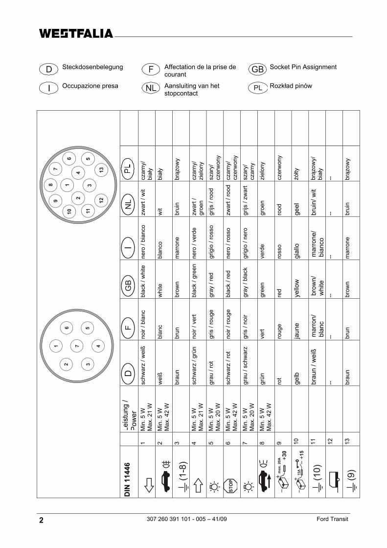
Belegungsplan
grau/schwarz Steuerleitung für Rücklicht links
schwarz/rot Steuerleitung für Bremslicht
grau/rot Steuerleitung für Standlicht rechts
grün Steuerleitung für Rückfahrscheinwerfer
Ford Transit 307 260 391 101 – 005 – 41/09 7
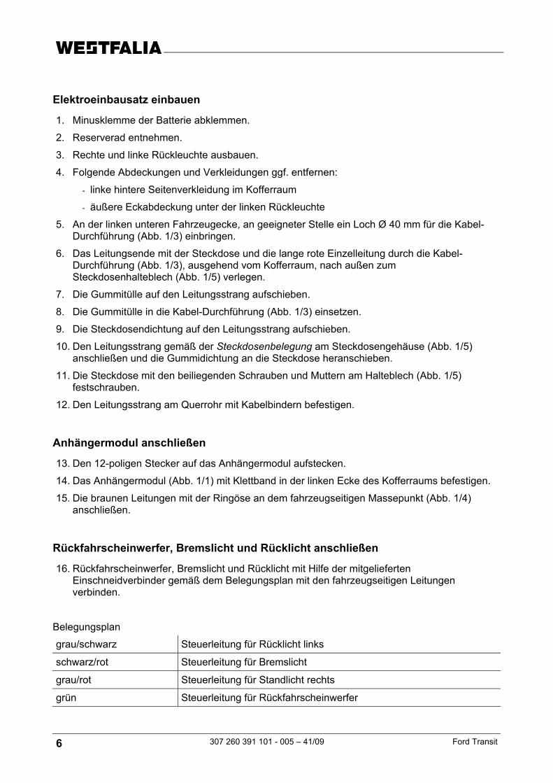
Blinkleuchten anschließen
17. Die Blinkleuchten gemäß nachfolgender Beschreibung anschließen.
Abb. 2: Anschluss Blinkleuchten
1 Blinkerschalter 5 rechte Blinkleuchte
2 Anhängermodul 6 linke Blinkleuchte
3 Kabel rot/grün 7 Kabel grün/weiß
4 Kabel grau/gelb 8 Kabel gelb
Hinweis Das Anhängermodul übernimmt die Steuerung der Blinkleuchten erst wenn die fahrzeugseitigen Blinkerleitungen durchtrennt (Abb. 2) wurden.
1
5
6
2
3 4
78
L
R
8 307 260 391 101 - 005 – 41/09 Ford Transit
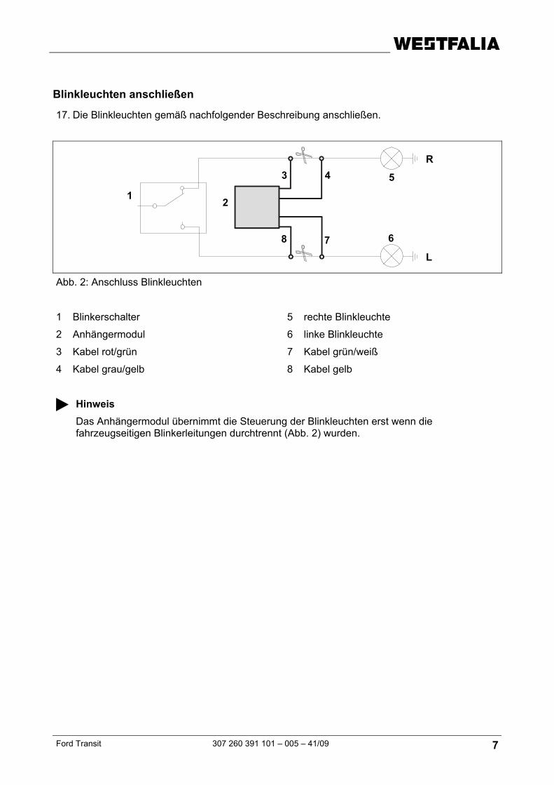
Nebelschlussleuchten anschließen
18. Die Nebelschlussleuchten gemäß nachfolgender Beschreibung anschließen.
Hinweis Befinden sich zwei Nebelschlussleuchten am Fahrzeug, die Zuleitung der zweiten Nebelschlussleuchte (Abb. 3/3) trennen und wie (Abb. 3/4) anschließen.
Hinweis Das Anhängermodul übernimmt die Steuerung der Nebelschlussleuchte erst wenn die fahrzeugseitigen Leitungen durchtrennt (Abb. 3) wurden.
Die Ansteuerung der Nebelschlussleuchte am Anhänger erfolgt direkt vom Steuergerät.
Funktion prüfen
19. Masse der Fahrzeugbatterie wieder anschließen.
20. Die Anhängerfunktionen mit einem geeigneten Prüfgerät (mit Belastungswiderständen) oder mit einem Anhänger prüfen.
21. Alle Leitungen mit Kabelbindern befestigen.
22. Alle ausgebauten Teile wieder einbauen.
1
3
4
2
56 L
R
Ford Transit 307 260 391 101 – 005 – 41/09 9
Instructions de montage : Installation électrique pour dispositif d’attelage
Données générales
Numéro d'article
Westfalia S.I.A.R.R
Véhicule
307 260 300 107 8884 Ford Transit Kasten / Combi à partir de 04/00
307 260 300 113 -- Ford Transit Kasten / Combi à partir de 04/00
Module d'extension plus permanent pour la prise de courant à 13 pôles
Remarque Le module d'extension plus permanent permet l'utilisation d'une alimentation en courant permanent et d'un fil de charge pour une batterie supplémentaire.
Numéro d'article
Westfalia Fabricant du véhicule
Véhicule
300 025 300 113 - - tous les véhicules
10 307 260 391 101 - 005 – 41/09 Ford Transit
Remarques importantes
Avant de commencer l'intervention, lire les instructions d'installation.
L'installation du module électronique ne doit être réalisée que par des techniciens qualifiés.
Attention - débrancher la batterie ! Endommagement de l'électronique du véhicule, les données enregistrées électroniquement peuvent être perdues.
Extraire la mémoire des erreurs avant de commencer l'intervention.
Avant de commencer à percer, s'assurer que rien ne se trouve derrière le revêtement, comme des fils par exemple.
Ebarber les endroits de la carrosserie qui sont polis, comme par exemple les trous alésés, puis appliquer de l'antirouille.
Remarque Observer avec attention les points suivants lors du montage :
• Les fils ne doivent pas être endommagés ou pincés.
• Installer tous les joints dans l'ordre établi.
• Disposer les fils de façon à ce qu'ils ne puissent pas frotter sur le véhicule ou rompre.
• Ne pas placer les fils à proximité immédiate du système d'échappement.
Lors de l'utilisation de la remorque, les feux anti-brouillard arrières du véhicule tractant sont mis à l'arrêt.
Pour les attelages sans feux anti-brouillard arrière, il faut en installer.
Toute panne d'un clignotant, également au niveau de l'attelage, est indiquée par une augmentation de la fréquence de clignotement. Aucun dispositif de contrôle supplémentaire des clignotants n'est nécessaire.
Un adaptateur de prise femelle ne doit être utilisé que pour le fonctionnement de l'attelage. Retirer cet adaptateur une fois que l'attelage n'est plus utilisé.
Tester le fonctionnement de l'attelage avec un attelage ou un dispositif de contrôle avec une résistance fixe.
Sous réserve de modifications techniques !
Ford Transit 307 260 391 101 – 005 – 41/09 11
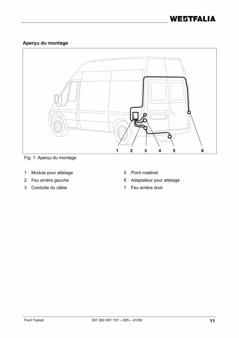
Aperçu du montage
Fig. 1: Aperçu du montage
1 Module pour attelage 5 Point matériel
2 Feu arrière gauche 6 Adaptateur pour attelage
3 Conduite du câble 7 Feu arrière droit
1 2 3 4 5 6
12 307 260 391 101 - 005 – 41/09 Ford Transit
Installation du module électronique
1. Débrancher la borne négative de la batterie.
2. Retirer la roue de secours.
3. Démonter les feux arrière droit et gauche.
4. Le cas échéant, retirer les revêtements et garnitures suivants :
- la garniture arrière gauche dans le coffre
- le revêtement du coin extérieur sous le feu arrière gauche
5. Au niveau du coin inférieur gauche du véhicule, percer un trou de 40 mm de diamètre à l'endroit adéquat pour le passe-câble (Fig. 1/3).
6. Faire passer l'extrémité du fil avec la prise via le passe-câble (Fig. 1/3), en partant du coffre à bagages vers l'extérieur, jusqu'à la tôle de retenue de la prise (Fig. 1/5).
7. Pousser le passe-fil en caoutchouc sur le conducteur de fils.
8. Insérer le passe-fil en caoutchouc dans le passage du câble (Fig. 1/3).
9. Pousser le joint de la prise de courant sur le conducteur de fils.
10. Connecter le conducteur de fils dans le bâti de la prise (Fig. 1/5) comme indiqué au paragraphe Affectation de la prise de courant et faire glisser vers le bas le joint en caoutchouc sur la prise.
11. Fixer la prise sur la plaque de retenue (Fig. 1/5) avec les vis et écrous fournis.
12. Fixer le conducteur de fils sur le tuyau transversal avec les attaches-câbles.
Raccorder le module pour attelage
13. Mettre la fiche à 12 pôles sur le module pour attelage.
14. Fixer le module pour remorque (Fig. 1/1) avec une bande velcro sur le coin gauche du coffre à bagages.
15. Raccorder les fils marron avec des anneaux sur le point matériel du côté du véhicule (Fig. 1/4).
Connecter le feu arrière, le feu stop et le feu de marche-arrière
16. Connecter le feu arrière, le feu stop et le feu de marche-arrière avec les fils côté véhicule en utilisant le connecteur à un tranchant livré et en respectant le plan d'occupation.
Plan d'occupation
gris/noir Ligne pilote pour le feu arrière gauche
noir/rouge Ligne pilote pour le feu stop
gris/rouge Ligne pilote pour le feu de position droit
vert Ligne pilote pour le feu de marche-arrière
Ford Transit 307 260 391 101 – 005 – 41/09 13
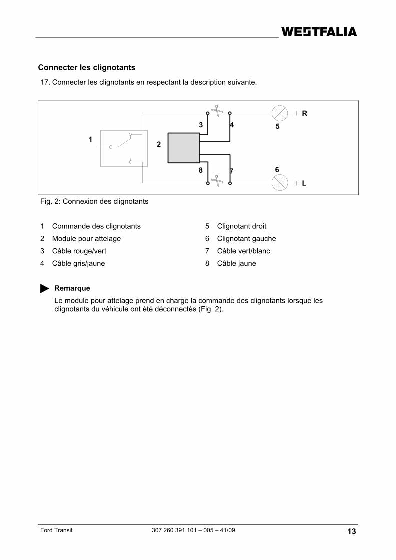
Connecter les clignotants
17. Connecter les clignotants en respectant la description suivante.
Fig. 2: Connexion des clignotants
1 Commande des clignotants 5 Clignotant droit
2 Module pour attelage 6 Clignotant gauche
3 Câble rouge/vert 7 Câble vert/blanc
4 Câble gris/jaune 8 Câble jaune
Remarque Le module pour attelage prend en charge la commande des clignotants lorsque les clignotants du véhicule ont été déconnectés (Fig. 2).
1
5
6
2
3 4
78
L
R
14 307 260 391 101 - 005 – 41/09 Ford Transit
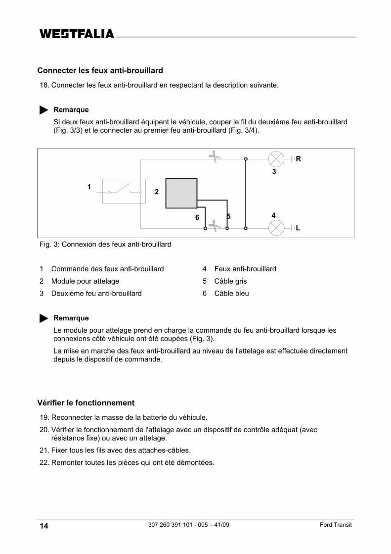
Connecter les feux anti-brouillard
18. Connecter les feux anti-brouillard en respectant la description suivante.
Remarque Si deux feux anti-brouillard équipent le véhicule, couper le fil du deuxième feu anti-brouillard (Fig. 3/3) et le connecter au premier feu anti-brouillard (Fig. 3/4).
Fig. 3: Connexion des feux anti-brouillard
1 Commande des feux anti-brouillard 4 Feux anti-brouillard
2 Module pour attelage 5 Câble gris
3 Deuxième feu anti-brouillard 6 Câble bleu
Remarque Le module pour attelage prend en charge la commande du feu anti-brouillard lorsque les connexions côté véhicule ont été coupées (Fig. 3).
La mise en marche des feux anti-brouillard au niveau de l'attelage est effectuée directement depuis le dispositif de commande.
Vérifier le fonctionnement
19. Reconnecter la masse de la batterie du véhicule.
20. Vérifier le fonctionnement de l'attelage avec un dispositif de contrôle adéquat (avec résistance fixe) ou avec un attelage.
21. Fixer tous les fils avec des attaches-câbles.
22. Remonter toutes les pièces qui ont été démontées.
1
3
4
2
56 L
R
Ford Transit 307 260 391 101 – 005 – 41/09 15
Installation Instructions: Electrical System For Towing Hitch
General Data
Part Number
Westfalia Vehicle Manufacturer
Vehicle
307 260 300 107 -- Ford Transit Van / Estate as of 04/00
307 260 300 113 -- Ford Transit Van / Estate as of 04/00
Constant plus extension kit for the 13-pin socket
Note The constant plus extension kit allows a permanent power supply and a charging lead for a booster battery to be used.
Part Number
Westfalia Vehicle Manufacturer
Vehicle
300 025 300 113 - - all vehicles
16 307 260 391 101 - 005 – 41/09 Ford Transit
Important Notes
Read the installation manual prior to starting work.
The electrical kit should only be installed by qualified personnel.
Caution – Disconnect the battery! Danger of damage to the vehicle’s electronic system. Data which are stored electronically may get lost.
Read out the fault storage prior to starting work.
Make sure prior to drilling that no objects such as cables, for example, are located behind the covers.
Deburr any bare body parts, like bore holes, and seal them with the help of some rust inhibitor.
Note During installation special attention has to be paid to the following points:
• Cables must not be pinched or damaged.
• All sealing elements have to be installed properly.
• Lay the cables such that they do not rub on the vehicle and are not bent.
• Do not lay any cables near the exhaust system.
When a trailer is used, the rear fog lamp of the traction vehicle is deactivated.
In the case of trailers without rear fog lamp, a rear fog lamp has to be retrofitted.
When a direction indicator lamp fails, also on the trailer, this is indicated by a higher flashing frequency. No additional direction indicator check is necessary.
A socket adapter may only be used in conjunction with a trailer. When the trailer is no longer used, remove the socket adapter.
Correct trailer operation has to be checked using a trailer or a test instrument with load resistors.
Subject to technical alterations!
Ford Transit 307 260 391 101 – 005 – 41/09 17
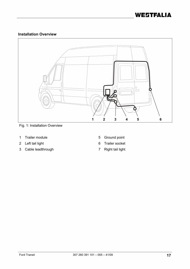
Installation Overview
Fig. 1: Installation Overview
1 Trailer module 5 Ground point
2 Left tail light 6 Trailer socket
3 Cable leadthrough 7 Right tail light
1 2 3 4 5 6
18 307 260 391 101 - 005 – 41/09 Ford Transit
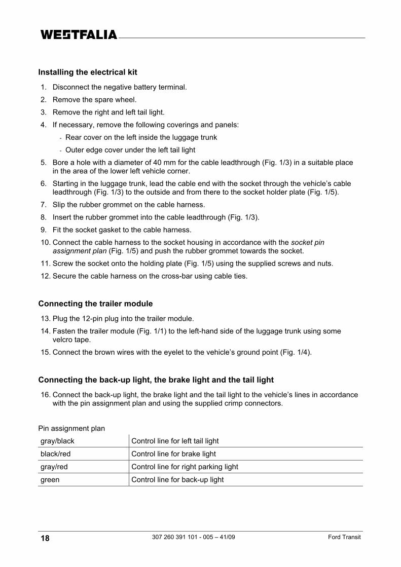
Installing the electrical kit
1. Disconnect the negative battery terminal.
2. Remove the spare wheel.
3. Remove the right and left tail light.
4. If necessary, remove the following coverings and panels:
- Rear cover on the left inside the luggage trunk
- Outer edge cover under the left tail light
5. Bore a hole with a diameter of 40 mm for the cable leadthrough (Fig. 1/3) in a suitable place in the area of the lower left vehicle corner.
6. Starting in the luggage trunk, lead the cable end with the socket through the vehicle’s cable leadthrough (Fig. 1/3) to the outside and from there to the socket holder plate (Fig. 1/5).
7. Slip the rubber grommet on the cable harness.
8. Insert the rubber grommet into the cable leadthrough (Fig. 1/3).
9. Fit the socket gasket to the cable harness.
10. Connect the cable harness to the socket housing in accordance with the socket pin assignment plan (Fig. 1/5) and push the rubber grommet towards the socket.
11. Screw the socket onto the holding plate (Fig. 1/5) using the supplied screws and nuts.
12. Secure the cable harness on the cross-bar using cable ties.
Connecting the trailer module
13. Plug the 12-pin plug into the trailer module.
14. Fasten the trailer module (Fig. 1/1) to the left-hand side of the luggage trunk using some velcro tape.
15. Connect the brown wires with the eyelet to the vehicle’s ground point (Fig. 1/4).
Connecting the back-up light, the brake light and the tail light
16. Connect the back-up light, the brake light and the tail light to the vehicle’s lines in accordance with the pin assignment plan and using the supplied crimp connectors.
Pin assignment plan
gray/black Control line for left tail light
black/red Control line for brake light
gray/red Control line for right parking light
green Control line for back-up light
Ford Transit 307 260 391 101 – 005 – 41/09 19
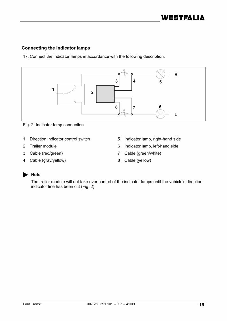
Connecting the indicator lamps
17. Connect the indicator lamps in accordance with the following description.
Fig. 2: Indicator lamp connection
1 Direction indicator control switch 5 Indicator lamp, right-hand side
2 Trailer module 6 Indicator lamp, left-hand side
3 Cable (red/green) 7 Cable (green/white)
4 Cable (gray/yellow) 8 Cable (yellow)
Note The trailer module will not take over control of the indicator lamps until the vehicle’s direction indicator line has been cut (Fig. 2).
1
5
6
2
3 4
78
L
R
20 307 260 391 101 - 005 – 41/09 Ford Transit
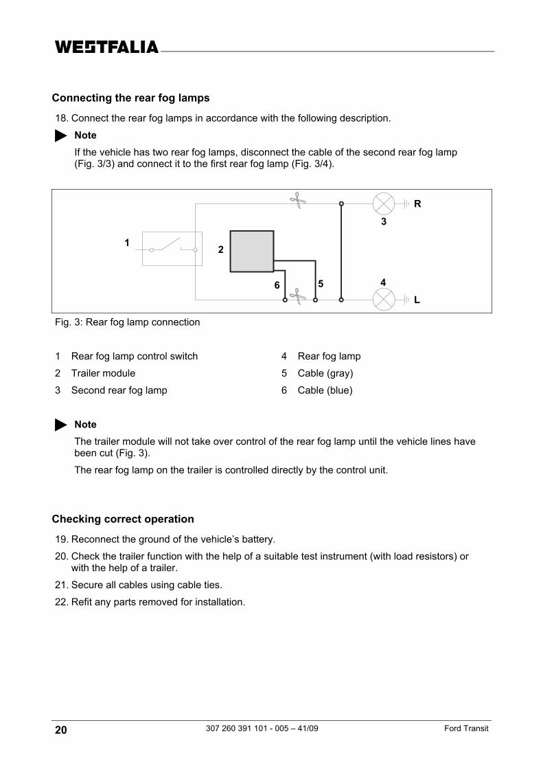
Connecting the rear fog lamps
18. Connect the rear fog lamps in accordance with the following description.
Note If the vehicle has two rear fog lamps, disconnect the cable of the second rear fog lamp (Fig. 3/3) and connect it to the first rear fog lamp (Fig. 3/4).
Fig. 3: Rear fog lamp connection
1 Rear fog lamp control switch 4 Rear fog lamp
2 Trailer module 5 Cable (gray)
3 Second rear fog lamp 6 Cable (blue)
Note The trailer module will not take over control of the rear fog lamp until the vehicle lines have been cut (Fig. 3).
The rear fog lamp on the trailer is controlled directly by the control unit.
Checking correct operation
19. Reconnect the ground of the vehicle’s battery.
20. Check the trailer function with the help of a suitable test instrument (with load resistors) or with the help of a trailer.
21. Secure all cables using cable ties.
22. Refit any parts removed for installation.
1
3
4
2
56 L
R
Ford Transit 307 260 391 101 – 005 – 41/09 21
Istruzioni per l'installazione: Impianto elettrico per il gancio di traino
Dati in generale
Codice articolo
Westfalia Costruttore veicolo
Veicolo
307 260 300 107 -- Ford Transit Kasten / Kombi a partire da 04/00
307 260 300 113 -- Ford Transit Kasten / Kombi a partire da 04/00
Kit ampliamento del positivo permanente per presa a 13 poli
Nota Il kit ampliamento del positivo permanente permette la messa in funzione dell'alimentazione della corrente continua e del circuito di carica per una batteria aggiuntiva.
Codice articolo
Westfalia Costruttore veicolo
Veicolo
300 025 300 113 - - tutti i veicoli
22 307 260 391 101 - 005 – 41/09 Ford Transit
Note importanti
Prima di iniziare i lavori, leggere le istruzioni di montaggio.
Il kit elettrico deve essere montato solo da personale qualificato.
Attenzione - Staccare la batteria! Danni all'elettronica del veicolo, i dati memorizzati possono essere persi.
Prima di iniziare consultare la memoria degli errori.
Prima di forare assicurarsi che dietro al rivestimento non ci siano oggetti, come per es. cablaggi.
Togliere la bava dai punti di carrozzeria nudi, come per es. dai bordi dei fori, e proteggerli con dell'antiruggine.
Nota Durante il montaggio prestare molta attenzione a quanto segue:
• I cavi non devono essere bloccati o danneggiati.
• Posizionare tutte le guarnizioni a regola d'arte.
• Posare i cablaggi in modo tale, che non sfreghino contro il veicolo e non risultino piegati.
• Non posare i cablaggi nelle immediate vicinanze dell'impianto gas di scarico.
In caso di funzionamento con rimorchio viene spenta la luce retronebbia del veicolo.
In caso di rimorchi non corredati di luce retronebbia, questa dovrà essere prevista.
Il guasto al lampeggiante direzionale, viene indicato anche al rimorchio con l'aumento dell'intermittenza. Non è necessario altro dispositivo di controllo del lampeggio.
La presa adattatore può essere impiegata solo in presenza del rimorchio. Staccando il rimorchio togliere anche la presa adattatore.
Verificare le funzioni con il rimorchio stesso oppure un dispositivo di misurazione con resistenze di carico.
Con riserva di modifiche tecniche!
Ford Transit 307 260 391 101 – 005 – 41/09 23
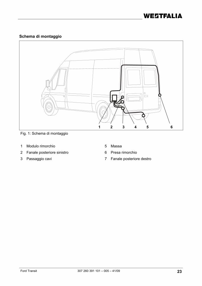
Schema di montaggio
Fig. 1: Schema di montaggio
1 Modulo rimorchio 5 Massa
2 Fanale posteriore sinistro 6 Presa rimorchio
3 Passaggio cavi 7 Fanale posteriore destro
1 2 3 4 5 6
24 307 260 391 101 - 005 – 41/09 Ford Transit
Montaggio kit elettrico
1. Staccare il morsetto negativo dalla batteria.
2. Togliere la ruota di scorta.
3. Smontare il fanale posteriore destro e sinistro.
4. Togliere ev. le seguenti coperture e rivestimenti:
- rivestimento laterale sinistro posteriore del bagagliaio
- protezione dell’angolo esterno sotto il fanale posteriore sinistro
5. Eseguire nell’angolo inferiore sinistro della vettura, nel punto adeguato, un foro Ø 40 mm per il passaggio dei cavi (fig. 1/3).
6. Infilare il terminale del fascio di cavi con la presa attraverso il passaggio cavi (1/3), partendo dal bagagliaio, verso l'esterno sino alla lamiera portapresa (fig. 1/5).
7. Infilare la bussola di gomma sul fascio di cavi.
8. Infilare la bussola di gomma nel passaggio cavi (fig. 1/3).
9. Infilare la guarnizione della presa sul fascio di cavi.
10. Inserire il contatto ad innesto nel corpo della presa (fig. 1/5) come da schema occupazione presa ed avvicinare la guarnizione di gomma alla presa.
11. Fissare la presa al supporto (fig. 1/5) mediante le viti ed i dadi forniti.
12. Fissare il fascio di cavi sulla traversina con delle fascette stringicavo.
Collegare il modulo del rimorchio
13. Inserire lo spinotto a 12 poli su detto modulo.
14. Fissare il modulo del rimorchio (fig. 1/1) con l'apposito nastro all'angolo sinistro del vano portabagagli.
15. Collegare i cavi marroni corredati degli occhielli alla massa del veicolo (fig. ¼).
Collegare la luce di retromarcia, luce di arresto e luce posteriore
16. Collegare i fanali di retromarcia, la luce di arresto e la luce posteriore impiegando l'attrezzatura apposita fornita come da schema, con i cavi del veicolo stesso.
Schema di collegamento
grigio/nero Cavo di comando luce posteriore sinistra
nero/rosso Cavo di collegamento luce di arresto
grigio/rosso Cavo di comando luce di positzione destra
verde Cavo di comando luci di retromarcia
Ford Transit 307 260 391 101 – 005 – 41/09 25
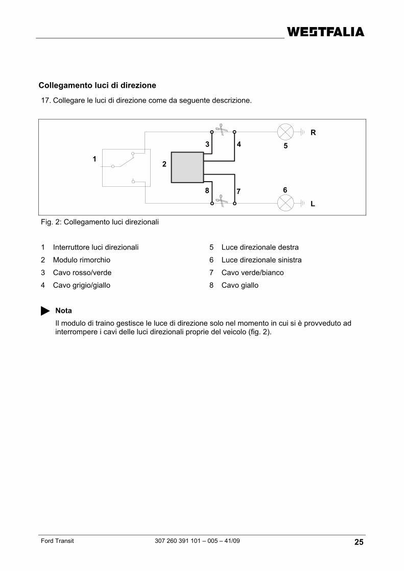
Collegamento luci di direzione
17. Collegare le luci di direzione come da seguente descrizione.
Fig. 2: Collegamento luci direzionali
1 Interruttore luci direzionali 5 Luce direzionale destra
2 Modulo rimorchio 6 Luce direzionale sinistra
3 Cavo rosso/verde 7 Cavo verde/bianco
4 Cavo grigio/giallo 8 Cavo giallo
Nota Il modulo di traino gestisce le luce di direzione solo nel momento in cui si è provveduto ad interrompere i cavi delle luci direzionali proprie del veicolo (fig. 2).
1
5
6
2
3 4
78
L
R
26 307 260 391 101 - 005 – 41/09 Ford Transit
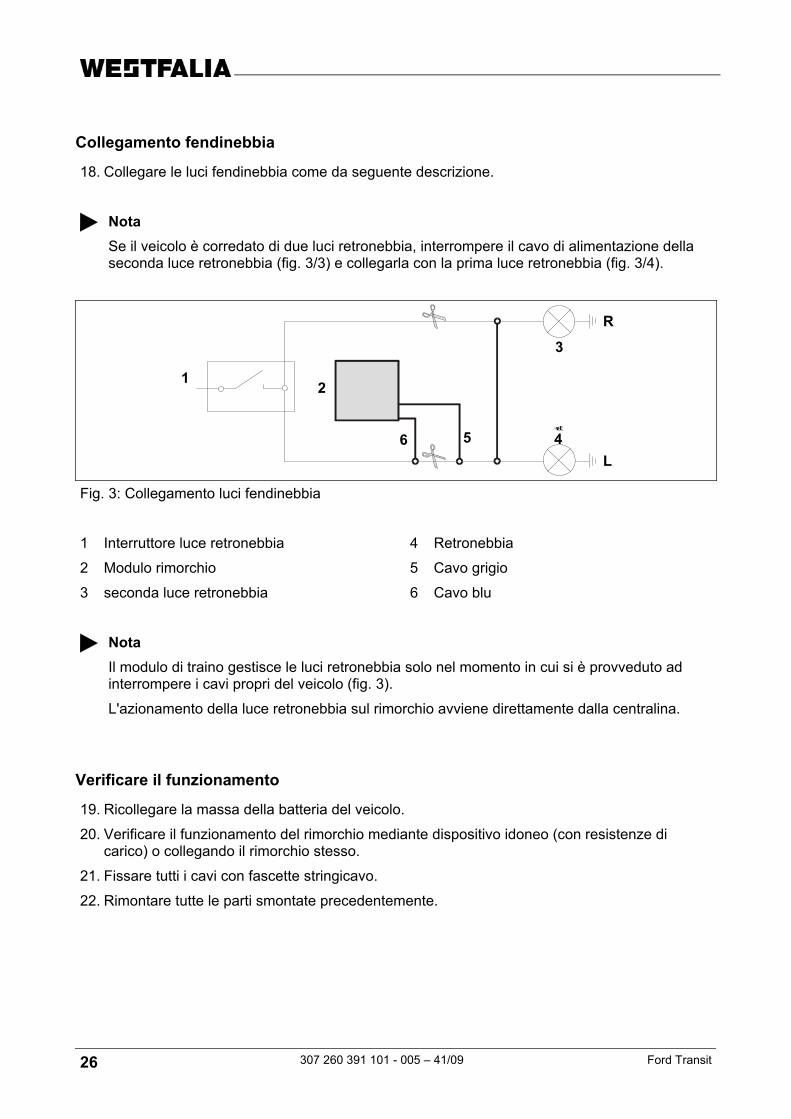
Collegamento fendinebbia
18. Collegare le luci fendinebbia come da seguente descrizione.
Nota Se il veicolo è corredato di due luci retronebbia, interrompere il cavo di alimentazione della seconda luce retronebbia (fig. 3/3) e collegarla con la prima luce retronebbia (fig. 3/4).
Fig. 3: Collegamento luci fendinebbia
1 Interruttore luce retronebbia 4 Retronebbia
2 Modulo rimorchio 5 Cavo grigio
3 seconda luce retronebbia 6 Cavo blu
Nota Il modulo di traino gestisce le luci retronebbia solo nel momento in cui si è provveduto ad interrompere i cavi propri del veicolo (fig. 3).
L'azionamento della luce retronebbia sul rimorchio avviene direttamente dalla centralina.
Verificare il funzionamento
19. Ricollegare la massa della batteria del veicolo.
20. Verificare il funzionamento del rimorchio mediante dispositivo idoneo (con resistenze di carico) o collegando il rimorchio stesso.
21. Fissare tutti i cavi con fascette stringicavo.
22. Rimontare tutte le parti smontate precedentemente.
1
3
4
2
56 L
R
Ford Transit 307 260 391 101 – 005 – 41/09 27
Inbouwinstructie: Elektrische installatie voor trekhaak
Algemene gegevens
Artikelnummer
Westfalia Fabrikant voertuig
Voertuig
307 260 300 107 -- Ford Transit bestelauto / stationcar vanaf 04/00
307 260 300 113 -- Ford Transit bestelauto / stationcar vanaf 04/00
Continu plus uitbreidingsset voor het 13-polige stopcontact
Pas op Met het continu plus uitbreidingsset is het mogelijk een continu spanningsvoorziening en een laadkabel voor een aanvullende accu te gebruiken.
Artikelnummer
Westfalia Fabrikant voertuig
Voertuig
300 025 300 113 - - alle voertuigen
28 307 260 391 101 - 005 – 41/09 Ford Transit
Belangrijke opmerkingen
Lees voor begin van de werkzaamheden de montagehandleiding door.
Het elektrische montageset mag uitsluitend worden gemonteerd door gekwalificeerd personeel.
Pas op – accu afklemmen! Beschadiging van de voertuigelectronica, elektronisch bewaarde gegevens kunnen verloren gaan.
Voor begin van de werkzaamheden foutgeheugen uitlezen.
Zorg voor het boren ervoor dat zich geen voorwerpen zoals b. v. leidingen achter de bekleding bevinden.
Blanke carrosserieonderdelen zoals b. v. boringen, moeten worden ontbraamd en aansluitend worden verzegeld met een roestbeschermend middel.
Pas op Let bij de montage vooral op de volgende punten:
• Leidingen mogen noch worden ingeklemd noch beschadigd.
• Alle dichtingselementen goed bevestigen.
• Leidingen zo leggen dat deze noch aan het voertuig wrijven noch knikken.
• Leidingen niet in de directe nabijheid van de uitlaatinstallatie leggen.
Bij rijden met een aanhanger wordt de mistachterlamp van het trekvoertuig uitgeschakeld.
Bij aanhangers zonder mistachterlamp moet deze achteraf worden geïnstalleerd.
Wanneer een richtingaanwijzer uitvalt, ook op de aanhanger, wordt dit aangegeven door het verhogen van de knipperfrequentie. Een aanvullende controle van de richtingsaanwijzers is niet nodig.
Een adapter voor de contactdoos mag uitsluitend worden gebruikt bij het rijden met aanhanger. Daarna moet de adapter worden verwijderd.
Controleer de aanhangerfuncties door het aansluiten aan een aanhanger of m.b.v. een proefapparaat met belastingsweerstanden.
Technische wijzigingen voorbehouden!
Ford Transit 307 260 391 101 – 005 – 41/09 29
Montageoverzicht
Fig. 1: Montageoverzicht
1 Aanhangermodule 5 Massapunt
2 Linker achterlamp 6 Aanhanger-stopcontact
3 Kabeldoorvoer 7 Rechter achterlamp
1 2 3 4 5 6
30 307 260 391 101 - 005 – 41/09 Ford Transit
Elektrisch montageset inbouwen
1. Minpol van de accu afklemmen.
2. Reservewiel verwijderen.
3. Rechter en linker achterlamp uitbouwen.
4. De volgende afdekkingen en bekledingen indien nodig verwijderen:
- linker achter zijbekleding in de kofferruimte
- buitenste hoekafdekking onder de rechter achterlamp
5. Boor op een geschikte plaats aan de linker onder voertuighoek een gat Ø 40 mm voor de kabeldoorvoer (fig. 1/3).
6. Het uiteinde van de kabel met het stopcontact en door de kabeldoorvoer (fig. 1/3) leggen, uitgaand van de kofferruimte naar buiten naar de stopcontact-bevestigingsplaat (fig. 1/5).
7. De rubberbus op de kabelbundel schuiven.
8. De rubberbus in de kabeldoorvoer (fig. 1/3) plaatsen.
9. De pakking van het stopcontact op de kabelbundel schuiven.
10. De kabelbundel overeenkomstig het aansluitschema stopcontact op het huis van de stopcontact (fig. 1/5) aansluiten en de rubberen pakking tegen het stopcontact aanschuiven.
11. Het stopcontact vastschroeven met de bijliggende schroeven en moeren op de montageplaat (fig. 1/5).
12. De kabelbundel op de dwarsligger met kabelbinders bevestigen.
Aanhangermodule aansluiten
13. De 12-polige stekker op de aanhangermodule opsteken.
14. De aanhangermodule (fig. 1/1) in de linker hoek van de kofferbak m.b.v. een klitteband bevestigen.
15. De bruine kabels met het ringoog op het massapunt van het voertuig (fig. 1/4) aansluiten.
Achteruitrijlamp, remlicht en achterlamp aansluiten
16. Achteruitrijlamp, remlicht en achterlamp met behulp van de bijliggende knip-connector volgens het aansluitschema met de leidingen van het voertuig verbinden.
Aansluitschema
grijs/zwart Regelleiding voor de linker achterlamp
zwart/rood Regelleiding voor het remlicht
grijs/rood Regelleiding voor het rechter parkeerlicht
groen Regelleiding voor achteruitrijlamp
Ford Transit 307 260 391 101 – 005 – 41/09 31
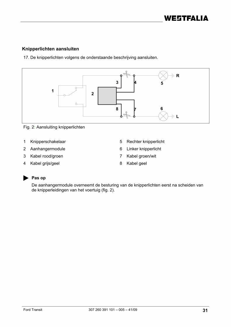
Knipperlichten aansluiten
17. De knipperlichten volgens de onderstaande beschrijving aansluiten.
Fig. 2: Aansluiting knipperlichten
1 Knipperschakelaar 5 Rechter knipperlicht
2 Aanhangermodule 6 Linker knipperlicht
3 Kabel rood/groen 7 Kabel groen/wit
4 Kabel grijs/geel 8 Kabel geel
Pas op De aanhangermodule overneemt de besturing van de knipperlichten eerst na scheiden van de knipperleidingen van het voertuig (fig. 2).
1
5
6
2
3 4
78
L
R
32 307 260 391 101 - 005 – 41/09 Ford Transit
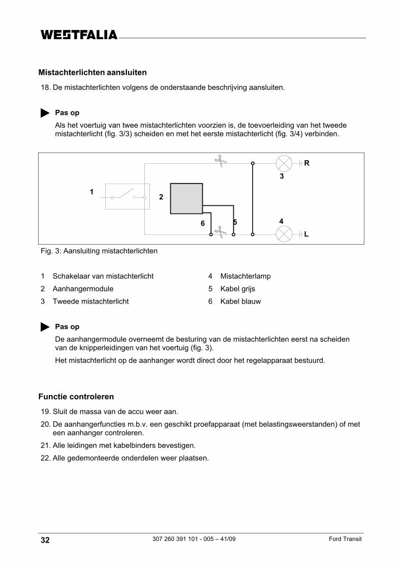
Mistachterlichten aansluiten
18. De mistachterlichten volgens de onderstaande beschrijving aansluiten.
Pas op Als het voertuig van twee mistachterlichten voorzien is, de toevoerleiding van het tweede mistachterlicht (fig. 3/3) scheiden en met het eerste mistachterlicht (fig. 3/4) verbinden.
Fig. 3: Aansluiting mistachterlichten
1 Schakelaar van mistachterlicht 4 Mistachterlamp
2 Aanhangermodule 5 Kabel grijs
3 Tweede mistachterlicht 6 Kabel blauw
Pas op De aanhangermodule overneemt de besturing van de mistachterlichten eerst na scheiden van de knipperleidingen van het voertuig (fig. 3).
Het mistachterlicht op de aanhanger wordt direct door het regelapparaat bestuurd.
Functie controleren
19. Sluit de massa van de accu weer aan.
20. De aanhangerfuncties m.b.v. een geschikt proefapparaat (met belastingsweerstanden) of met een aanhanger controleren.
307 260 300 107 -- Ford Transit Kasten/Kombi od 04/00
307 260 300 113 -- Ford Transit Kasten/Kombi od 04/00
Zestaw rozszerzający funkcji stałego plusa do 13-biegunowego gniazda
Wskazówka Zestaw rozszerzający funkcji stałego plusa umożliwia zastosowanie stałego zasilania prądem oraz przewodu ładowania dla dodatkowego akumulatora.
Numer artykułu
Westfalia Producent pojazdu
Pojazd
300 025 300 113 -- Wszystkie pojazdy
34 307 260 391 101 - 005 – 41/09 Ford Transit
Ważne wskazówki
Przed rozpoczęciem pracy przeczytaj instrukcję montażu.
Elektroniczny zestaw montażowy może zostać zamontowany wyłącznie przez wykwalifikowany personel.
Uwaga – odłącz zaciski od akumulatora! Uszkodzenie elektroniki pojazdu może doprowadzić do utraty danych elektronicznych.
Przed rozpoczęciem pracy zabezpiecz dane zapisane w pamięci błędów na innym nośniku.
Przed rozpoczęciem wiercenia sprawdź, czy za osłonami nie znajdują się żadne przedmioty, np. przewody.
Usuń zadziory z niezabezpieczonych miejsc karoserii, np. z wywierconych otworów, a następnie pokryj je środkiem antykorozyjnym.
Wskazówka Podczas montażu zwróć szczególną uwagę na następujące punkty:
• Przewody nie mogą być zaklinowane ani uszkodzone.
• Prawidłowo zamontuj wszystkie elementy uszczelniające.
• Poprowadź przewody tak, aby nie zaginały się i nie ocierały o pojazd.
• Nie kładź przewodów w bezpośredniej bliskości układu wydechowego.
W pojeździe holującym przyczepę wyłączone jest tylne światło przeciwmgielne.
Jeśli przyczepa nie posiada tylnego światła przeciwmgielnego, należy je zamontować.
Awaria kierunkowskazu, również kierunkowskazu przyczepy, sygnalizowana jest poprzez zwiększoną częstotliwość migania kontrolki. Dodatkowa kontrola kierunkowskazów nie jest konieczna.
Adapter gniazda może być używany tylko w trakcie holowania przyczepy. Po zakończeniu holowania należy go wymontować.
Funkcje przyczepy należy sprawdzić z podłączoną przyczepą lub za pomocą przyrządu kontrolnego z opornością obciążenia.
Zmiany techniczne zastrzeżone!
Ford Transit 307 260 391 101 – 005 – 41/09 35
Schemat montażowy
Rys. 1: Schemat montażowy
1 Moduł sterownia przyczepą 4 Punkt masy
2 Lewe światło tylne 5 Gniazdo wtykowe przyczepy
3 Przepust kablowy 6 Prawe światło tylne
1 2 3 4 5 6
36 307 260 391 101 - 005 – 41/09 Ford Transit
Montaż zestawu elektronicznego
1. Odłącz ujemny zacisk akumulatora.
2. Wyjmij koło zapasowe.
3. Wymontuj prawe i lewe światło tylne.
4. W razie potrzeby zdejmij następujące pokrywy i osłony:
- lewa tylna osłona w bagażniku,
- zewnętrzna pokrywa narożna pod lewym światłem tylnym.
5. W lewym dolnym rogu pojazdu wykonaj w odpowiednim miejscu otwór Ø 40 mm na przepust kablowy (rys. 1/3).
6. Wyprowadź końcówkę przewodu z wtykiem oraz długi pojedynczy przewód koloru czerwonego przez przepust kablowy (rys. 1/3) z bagażnika na zewnątrz do blaszanego uchwytu gniazda (rys. 1/5).
7. Nałóż przelotkę gumową na wiązkę przewodów.
8. Włóż przelotkę gumową do przepustu kablowego (rys. 1/3).
9. Na wiązkę przewodów nałóż uszczelkę.
10. Podłącz wiązkę przewodów zgodnie z rozkładem pinów do obudowy gniazda wtykowego (rys. 1/5) i dosuń uszczelkę gumową do gniazda.
11. Przykręć gniazdo wtykowe do blaszanego uchwytu (rys. 1/5) za pomocą dostarczonych śrub i nakrętek.
12. Przymocuj wiązkę przewodów do belki poprzecznej za pomocą opasek kablowych.
Podłączanie modułu przyczepy
13. Włóż 12-biegunowy wtyk do modułu przyczepy.
14. Zamocuj moduł przyczepy (rys. 1/1) za pomocą taśmy przyczepnej w lewym rogu bagażnika.
15. Podłącz brązowe przewody z uchwytem pierścieniowym do punktu masy pojazdu (rys. 1/4).
Podłączanie światła cofania, światła stopu oraz światła tylnego
16. Podłącz przewody do światła cofania, światła stopu oraz światła tylnego za pomocą dostarczonych łączników do naciętych izolacji zgodnie z rozkładem pinów.
Rozkład pinów
szary/czarny przewód sterujący do lewego światła tylnego
czarny/czerwony przewód sterujący do światła stopu
szary/czerwony przewód sterujący do prawego światła postojowego
zielony przewód sterujący do światła cofania
Ford Transit 307 260 391 101 – 005 – 41/09 37
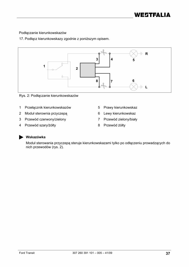
Podłączanie kierunkowskazów
17. Podłącz kierunkowskazy zgodnie z poniższym opisem.
Wskazówka Moduł sterowania przyczepą steruje kierunkowskazami tylko po odłączeniu prowadzących do nich przewodów (rys. 2).
1
5
6
2
3 4
78
L
R
38 307 260 391 101 - 005 – 41/09 Ford Transit
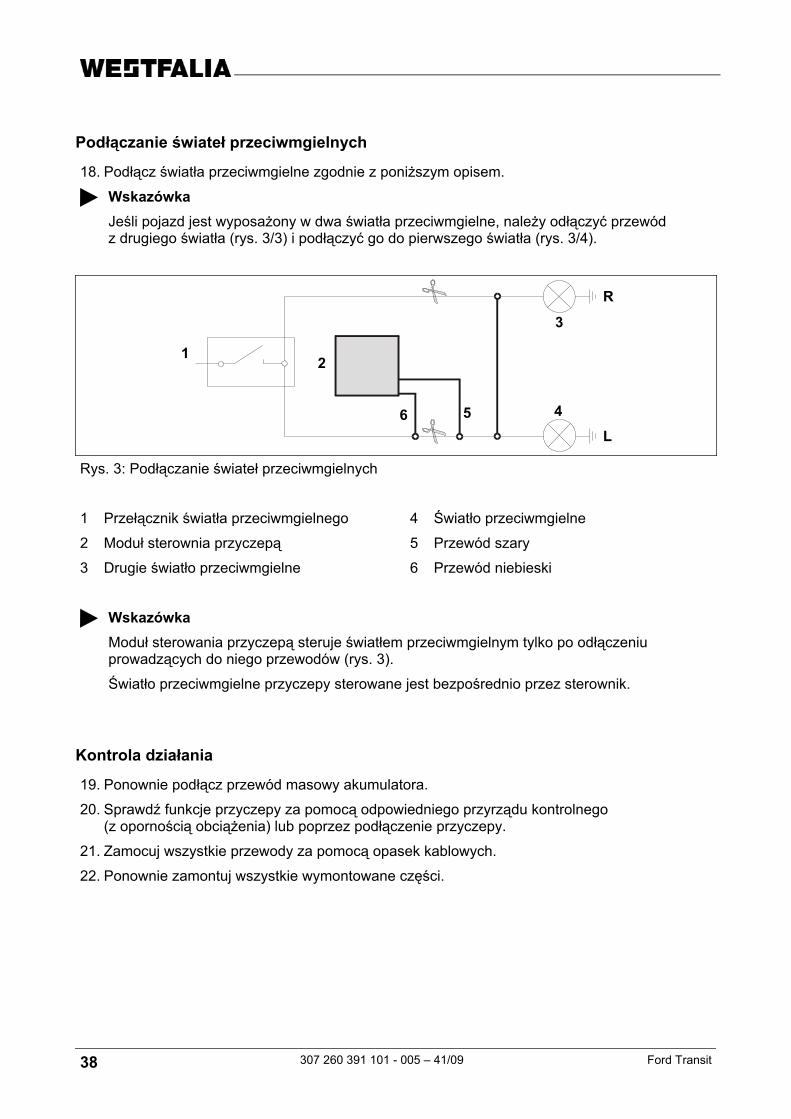
Podłączanie świateł przeciwmgielnych
18. Podłącz światła przeciwmgielne zgodnie z poniższym opisem.
Wskazówka Jeśli pojazd jest wyposażony w dwa światła przeciwmgielne, należy odłączyć przewód z drugiego światła (rys. 3/3) i podłączyć go do pierwszego światła (rys. 3/4).
Rys. 3: Podłączanie świateł przeciwmgielnych
1 Przełącznik światła przeciwmgielnego 4 Światło przeciwmgielne
2 Moduł sterownia przyczepą 5 Przewód szary
3 Drugie światło przeciwmgielne 6 Przewód niebieski
Wskazówka Moduł sterowania przyczepą steruje światłem przeciwmgielnym tylko po odłączeniu prowadzących do niego przewodów (rys. 3).
Światło przeciwmgielne przyczepy sterowane jest bezpośrednio przez sterownik.
Kontrola działania
19. Ponownie podłącz przewód masowy akumulatora.
20. Sprawdź funkcje przyczepy za pomocą odpowiedniego przyrządu kontrolnego (z opornością obciążenia) lub poprzez podłączenie przyczepy.
21. Zamocuj wszystkie przewody za pomocą opasek kablowych.
22. Ponownie zamontuj wszystkie wymontowane części.