D RESDEN U NIVERSITY OF T ECHNOLOGY DEPARTMENT OF C OMPUTER S CIENCE I NSTITUTE OF S OFTWARE AND MULTIMEDIA T ECHNOLOGY C HAIR OF C OMPUTER GRAPHICS AND VISUALIZATION P ROF.DR .S TEFAN GUMHOLD Diplomarbeit zur Erlangung des akademischen Grades Diplom-Medieninformatiker Development of a behavioural animation system and control mechanisms for Autonomous Agents Johannes Richter (Born 23rd October 1980 in Goerlitz) Tutor: Prof. Dr. rer. nat. S. Gumhold Dresden, May 31, 2006
Transcript
DRESDEN UNIVERSITY OF TECHNOLOGY
DEPARTMENT OF COMPUTER SCIENCE
INSTITUTE OF SOFTWARE AND MULTIMEDIA TECHNOLOGY
CHAIR OF COMPUTER GRAPHICS AND VISUALIZATION
PROF. DR. STEFAN GUMHOLD
Diplomarbeit
zur Erlangung des akademischen GradesDiplom-Medieninformatiker
Development of a behavioural animation system andcontrol mechanisms for Autonomous Agents
Johannes Richter(Born 23rd October 1980 in Goerlitz)
Tutor: Prof. Dr. rer. nat. S. Gumhold
Dresden, May 31, 2006
Aufgabenstellung
Goal of this thesis is the development of an agent based animation system and the design of structures tocontrol behavioural animation. This work is to be seen as an interface between principles of behavioursimulation, concepts of computer graphics and requirements of film- and animation production. Withinthis thesis following problems are to be handled:
• Derivation of agent based animation concepts from artificial intelligence and computer graphics
• Conceptual design and implementation of a flexible behavioural animation system
• Development of control structures for dedicated influence of the behaviour of autonomous agentswithin the given animation system
• Creation and analysis of scenarios to demonstrate the simulation system and developed controlstructures
Selbstständigkeitserklärung
Hiermit erkläre ich, dass ich die von mir am heutigen Tag dem Prüfungsausschuss der Fakultät Infor-matik eingereichte Diplomarbeit zum Thema:
Development of a behavioural animation system and control mechanisms for Autonomous Agents
vollkommen selbstständig verfasst und keine anderen als die angegebenen Quellen und Hilfsmittel be-nutzt sowie Zitate kenntlich gemacht habe.
A Adapting HANIBAL 81A.1 creating a User Interface for a custom Workspace Element . . . . . . . . . . . . . . . . 81A.2 Implementing new Control Entities . . . . . . . . . . . . . . . . . . . . . . . . . . . . . 82A.3 Implementing a new Stage System . . . . . . . . . . . . . . . . . . . . . . . . . . . . . 82
B Class Diagrams of HANIBAL 83
Bibliography 86
List of Figures 88
1. MOTIVATION 3
1 Motivation
Films always enlightened people. Since the beginning of cinema the moving images created entire worldsof unseen spectacle. They are mysterious as the robot-woman Maria in Fritz Langs Metropolis. Theyare astonishing as Ray Harryhausens sword fighting skeletons in Jason and the Argonauts. They arespectacular as Industrial Light and Magics dinosaurs populating Spielbergs Jurassic Park.The hunger for more excitement, more miraculous places was a driving force in the development of newtechnologies advancing not only the quality of the moving images, but of the storytelling itself. Storieswhich have been considered impossible to picturise made their way to the big screen by the help of com-puter graphics. New ways of representing gigantic three dimensional worlds, new methods of modelling,rendering, lighting, combining real action footage with CG material paved the way for cinema in thestyle of the 21st century. The path from the first hand drawn sketches of Mickey Mouse to photo realisticvisual effect monsters like King Kong has been very long and many technological advances have beenmade on the way.A very recent development in visual effects and animation is the facilitation of behavioural concepts tocontrol artificial characters of a film. In this thesis we want to put a light on different approaches forbehavioural animation and develop a common concept for the creation of a simulation system whichcould end up being used in a production pipeline.The presented concept is supposed to provide a common ground for the different approaches alreadypublished and will allow to make use of their advantages by being flexible enough to interlink theseelements in a modular structure.The behavioural animation system called HANIBAL has been developed as part of this thesis and im-plements the introduced concept. It gives an insight in the actual realisation of the shown concept. Bythe use of several scenarios we demonstrate how HANIBAL can be used to create behavioural simulationcontents for animation production.Behavioural animation is accompanied by a whole field of new problems. Introducing autonomously act-ing characters into animation production also comes with loosing control about their actual behaviour.We discuss this problem by designing a concept for control structures and implementing a set of actualtools which can be used to influence behavioural decisions in a simulation run.We are going to start with the roots of animation and continue to introduce basic concepts of the designof autonomous agents. This will lead us to different concepts of behavioural animation and eventually tothe guidelines for the creation of a behavioural animation system like HANIBAL .
2. PRINCIPLES OF ANIMATION 4
2 Principles of Animation
A five minute animated film consists of 7500 single frames. Each one of these frames is usually differentfrom any other. They have to be created one by one to create the illusion of movement on the screen.Of course they aren’t completely drawn from scratch. From early on methods have been developed tominimize the workload of animators.In computer animation the hardware can carry a lot of this load and provide some very efficient tools.To see where the principles for behaviour based animation with autonomous agents root from, the follow-ing section will provide a brief walk through along the important concepts of animation. It is consideredas a general overview relating to other works for further details.
2.1 Keyframing
Keyframing comes from the early days of animated film. Artists working on a classic hand drawn an-imation first draw the most important elements of the sequence. They create key frames. This givesan impression of how the entire sequence will look like, before it is actually completed. After gettingconfirmation from the director more frames - so called interframes - are drawn in between. Every step ofrefining the work gets approved and the whole procedure is repeated until the entire sequence is done.
Figure 2.1: key frames of a simple walk cycle
This structure of top to bottom work gets mirrored in the hierarchy of people working in this process.While a director gives the general key points, senior animators will only draw a set of key frames and thefirst intermediates. The real frame by frame work to connect the key frames - sometimes referred to astweening - can be done by less experienced animators, because they work on very clear guidelines.In computer animation the calculation of intermediates is done by the computer itself. Frame elementsare represented by a complex set of numeric parameters, whose values can easily be interpolated betweendifferent time steps. The artist only has to provide some information about the way this interpolation hasto be done.In the further chapters we will refer to this kind of animation as discreet animation, pointing out to its
2. PRINCIPLES OF ANIMATION 5
explicit character of defining the actual animated content. Behavioural animation on the other hand israther implicit, because it defines the actual animation as the emergent result of a behavioural simulation.
Figure 2.2: The graph editor of Alias Wavefronts MAYA
Numeric interpolation provides the artist with an additional set of tools. A mathematic graph represen-tation of animated parameters can be used to fine tune an animation precisely. Especially to maintain anatural flow of movements it is very helpful to get discreet feedback on continuity.
2.2 Rigging Controls
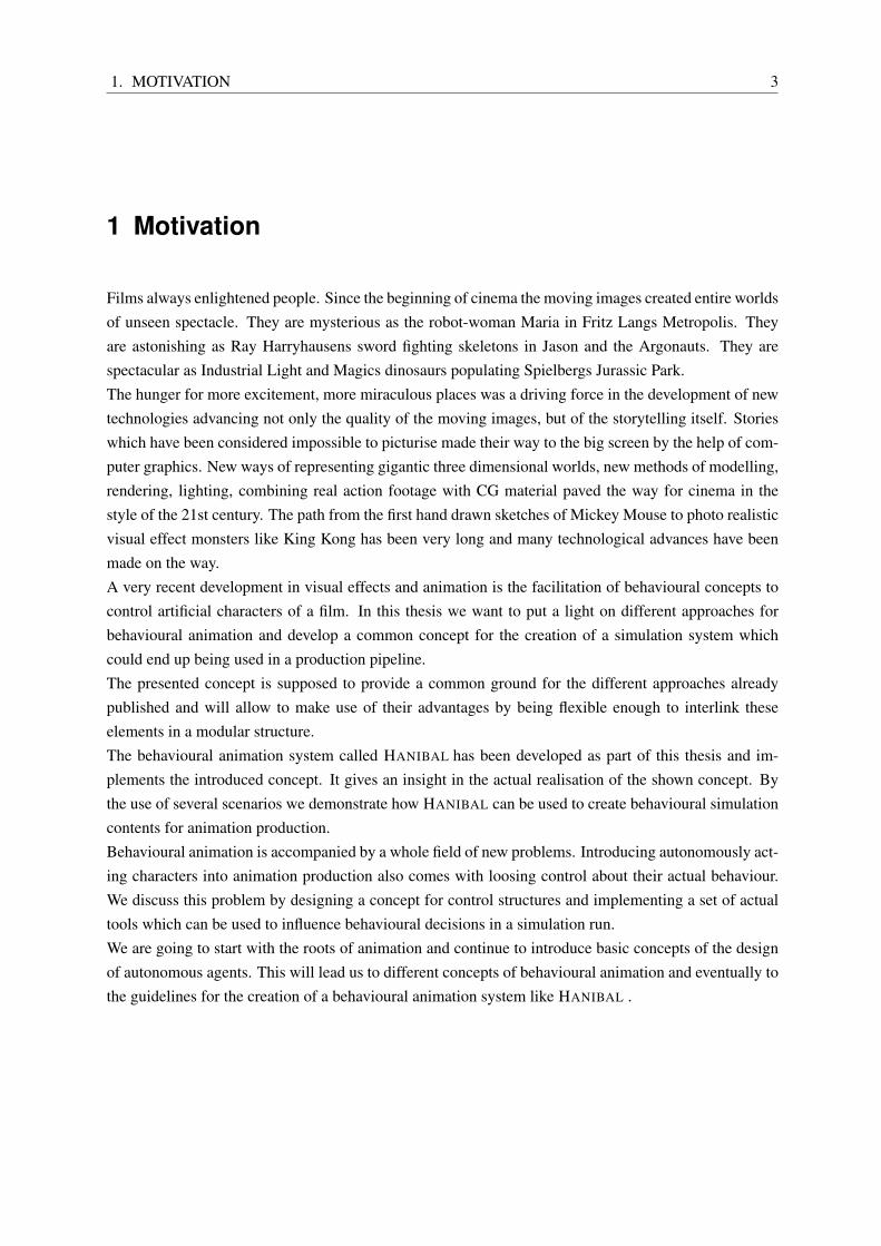
Although computer based animation has its advantages there is still a lot of overhead compared to handdrawn frames. This is due to the nature of geometric representation of three dimensional objects. A threedimensional arm model does not consist of a couple of drawn lines, it is a complex mesh of vertices orcontrol points which are by far less flexible in handling then a pencil stroke.There are plenty of approaches for simplifying mesh control. They all have in common, to cluster partsof geometric attributes to provide manipulation controls of different sharpness. Superordinate transfor-mations on controls are applied on actual geometry, often using corresponding weighting information. Agood example would be vertex clustering and weighted mesh skinning with bones.
Inverse Kinematics are controls of an even higher order, usually manipulating a bone structure. A properset-up of an animated character consist of a complex hierarchy of mesh controls of varying coarseness.In a production pipeline these so called character rigs are drawn to a very high level of simplification.All the animation work is often done by people who are by far more skilled in acting and arts than incontrolling 3D Animation Software. The quality of their delivered work seems to be the best proof forthe concept.
2. PRINCIPLES OF ANIMATION 6
Figure 2.3: a character rig showing movement handles for animators
2.3 Character Sets and Track Editing
These principles base on another key attribute of animation, especially in feature length films - repetition.A character set is basically just a clearly defined set of attributes belonging to a certain character of asequence. This character can be a real character like a singing kettle or a cave monster, or it is less plasticand stands for a part of a machine or is sometimes just a tree. Character sets can be set up in a hierarchy,so that a set contains different subsets which can be referred to on their own or as part of their parent set.In a production process it happens often, that certain attribute settings in a character set appear more thanonce. It is useful to store this reoccurring setting separately. Such a setting is called a pose.A certain facial expression could be a pose, or a distinct body pose. All poses are stored in a library andcan be applied to a selected character in one step. It is even possible to transfer a pose from one characterto another. This is extremely handy, if different characters have a similar set-up and with very simpletransfer operations - e.g. for matching different attribute names - it is possible to reuse work which hasalready been done.The principle of poses can be pushed one step further. It is possible to store entire sequences of animatedattributes in clips. Clips work exactly like poses do, they can be applied whenever needed and even trans-ferred between different characters. This allows maximum efficiency when animating a lot of differentcharacters. Basic animations like walking or running are generally the same. Even if some variations arenecessary, they can be easily done by manipulating a prepared clip.Due to the fact that clips and poses always work on the same character set or character subset, they caneven be interpolated. Blending from pose to pose, blending of different clips, combinations of severalanimations at the same time. All these things are imaginable and can be achieved with low effort
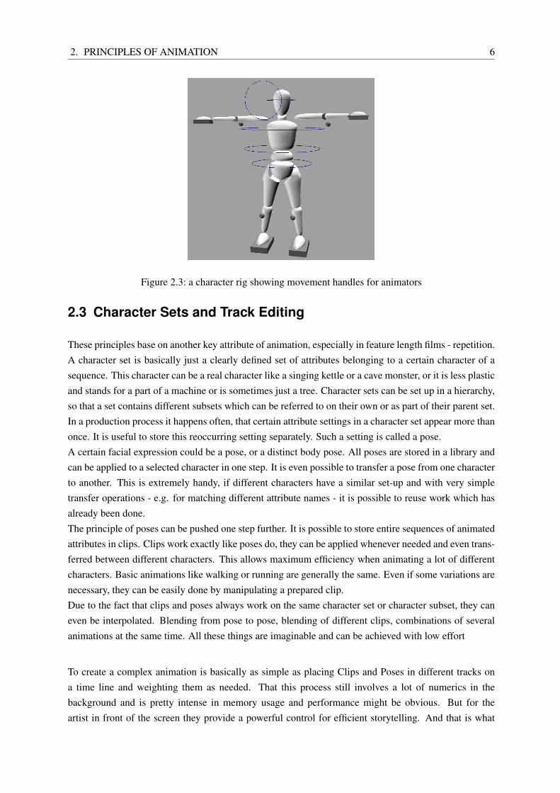
To create a complex animation is basically as simple as placing Clips and Poses in different tracks ona time line and weighting them as needed. That this process still involves a lot of numerics in thebackground and is pretty intense in memory usage and performance might be obvious. But for theartist in front of the screen they provide a powerful control for efficient storytelling. And that is what
2. PRINCIPLES OF ANIMATION 7
Figure 2.4: trax editing in MAYA
everything is about.
2.4 Physical based animation
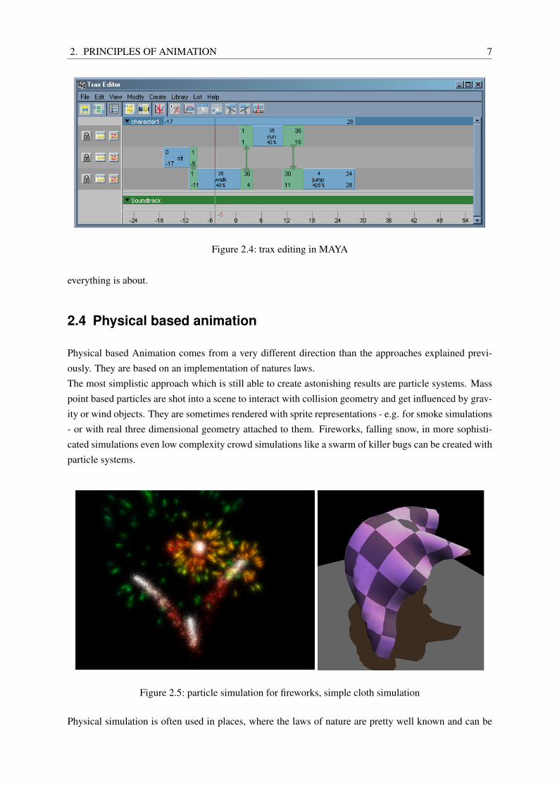
Physical based Animation comes from a very different direction than the approaches explained previ-ously. They are based on an implementation of natures laws.The most simplistic approach which is still able to create astonishing results are particle systems. Masspoint based particles are shot into a scene to interact with collision geometry and get influenced by grav-ity or wind objects. They are sometimes rendered with sprite representations - e.g. for smoke simulations- or with real three dimensional geometry attached to them. Fireworks, falling snow, in more sophisti-cated simulations even low complexity crowd simulations like a swarm of killer bugs can be created withparticle systems.
Figure 2.5: particle simulation for fireworks, simple cloth simulation
Physical simulation is often used in places, where the laws of nature are pretty well known and can be
2. PRINCIPLES OF ANIMATION 8
imitated in a way which produces believable results in reasonable time. An important example is clothsimulation, something which is hard to achieve by hand, even as an experienced animator. From simu-lating realistic cloth [14], fur and hair [11] or even complex fluid simulations [18] are part of productionpackages and receive a visual quality barely distinguishable from reality.But physical simulations have their flaws. They are often very costly in terms of performance and some-times have unpredictable results. They just behave like nature does, which not seldom collides with therequirements of the script of an adventure movie.
2.5 Going Further
Wouldn’t it be nice to go one step further and be able to concentrate fully on the narrative componentof a film? Once it is clear what will happen, isn’t the job of an animator tracking together sequences ofmotion something which could be automated?The next section will introduce a complete different field. It will cover some ground on the concept ofAutonomous Agents and principles of Artificial Intelligence. Eventually we will get back to methods wejust discussed to introduce the behaviour based animation system developed in this thesis.
3. AUTONOMOUS AGENTS 9
3 Autonomous Agents
The notion of artificial intelligence is not really new. Aristotle (384-322 B.C.) already discussed ques-tions of finding formal rules for proper reasoning. Over the course of time many different fields ofscience pushed the boundaries of creating a thinking machine, yet only with the invention of computersthe developments lifted of and gained a pace which lead to promising results. But artificial intelligence isnot a pure technical or numeric question. It is a question touching some very delicate areas of philosophy,of ethics and the essence of a humans soul.We won’t try to cover all of these grounds, but take some thoughts of this field as inspiration for creatingautonomous acting characters for animation purposes. For a detailed introduction it is recommended tohave a look at Artificial Intelligence - A Modern Approach by Stuart Russell and Peter Norvig [17] whichhas been a great source of information contributing to this thesis.
3.1 What is an Agent?
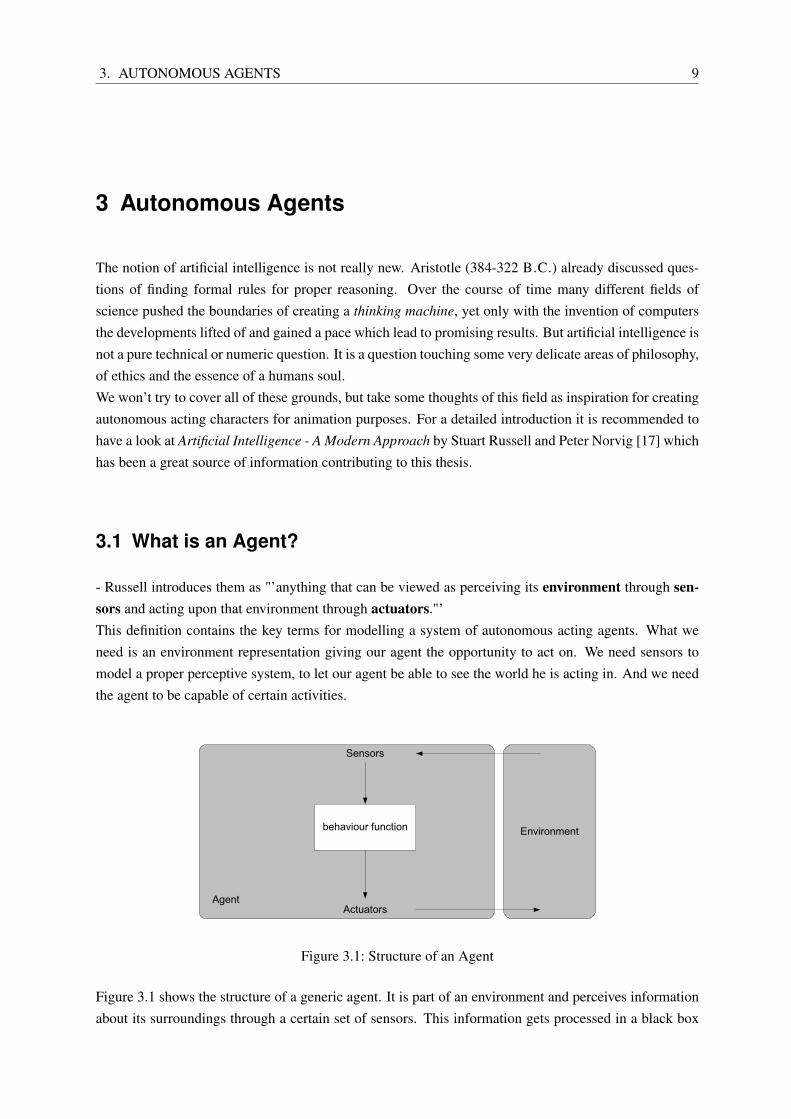
- Russell introduces them as "’anything that can be viewed as perceiving its environment through sen-sors and acting upon that environment through actuators."’This definition contains the key terms for modelling a system of autonomous acting agents. What weneed is an environment representation giving our agent the opportunity to act on. We need sensors tomodel a proper perceptive system, to let our agent be able to see the world he is acting in. And we needthe agent to be capable of certain activities.
Agent
Environment
Sensors
Actuators
behaviour function
Figure 3.1: Structure of an Agent
Figure 3.1 shows the structure of a generic agent. It is part of an environment and perceives informationabout its surroundings through a certain set of sensors. This information gets processed in a black box
3. AUTONOMOUS AGENTS 10
which we will call its behaviour function. The results of these calculations will guide to a set of activitiesperformed in or towards the environment. Varying external influences will lead to a certain behaviourperformed by the agent.So far this will result in some kind of activity, but without any direction. What we need is what Russelldefines as performance measure, giving feedback on an agents success. Our generic agent becomes arational agent, capable of judging its own behaviour.
The Rational AgentFor each possible percept sequence, a rational agent should select an action that is expectedto maximize its performance measure, given the evidence by the percept sequence and what-ever built-in knowledge the agent has.
Having introduced all these terms describing our agents world, they will be discussed in more detailleading to the construction of our animation system.
3.2 Environment
Due to the fact, that it is the agents only source of information for triggering and influencing its be-haviour, it is next to the actual behaviour implementation the most important part of our simulation.Speaking in Russells Properties of Task Environments [17] we basically deal with a partially or fullyobservable, stochastic, sequential, static or dynamic, continuous multi agent environment.An agent might be able to perceive the whole world at once, but does not necessarily have to, to performthe wanted activities.The environment is definitely stochastic, because it is unforeseeable. It is not predictable how the envi-ronment will look like in the next step of the simulation. It isn’t just the result of the current state of theenvironment and our agents reaction to it. There might be direct interference of the animator by trigger-ing control instruments, it isn’t said how other agents will act or the state of the environment changesitself.Sequentiality means, that the environment does not come in atomic episodes being unrelated to eachother. Every decision our agent takes will have influence on the following.Depending on the implementation of the behaviour system our environment will be static or dynamic. Ina multi threaded system the environment can easily change during the decision process of the agent. Inthe implementation of HANIBAL it is designed single threaded and therefore could be considered static.The type of environments an agent based animation will run in will usually be a continuous system. Itdoesn’t have a distinct number of states it can exist in. Russell distinguishes between time-continuousand state-continuous environments. In an animation process we will deal with a time-discrete simulationperforming a certain number of steps per frame, although it will be state continuous, due to the nature ofthe requirements of an animation.Finally we deal with a multi agent system. It actually depends on the actual type of simulation which isdesigned, to decide if it is a competitive or cooperative multi agent system. In most cases it will be a mixof both.
3. AUTONOMOUS AGENTS 11
3.3 Performance Measure
In a real world agent application the performance measure is of very high importance. It gives feedbackon the outcomes of an agents decisions and therefore represents a selector for the action to take. In ananimation process the performance measure becomes a tool of soft influence on the overall look of thefinal scene.Imagine a stadium simulation with a good sized audience represented by autonomous agents. It is of nopractical importance how many fans in a virtual stadium actual clap their hands or yell at the same timeor how these clapping and yelling people are distributed in the stadium. But it is important, that it looksbelievable.At this point it is important to keep in mind, that the performance measure is only the measure for thebehaviour of one single agent. It won’t necessarily relate to the overall quality of the final scene.For a fan in the stadium a good performance measure would be the variability of his motions, the believ-ability of his reactions to the game, to his neighbours and to the laws of his own physical conditions. Afan getting up and sitting down repeatedly will be considered wrong or bad. A fan agent behaving closeto what ourself would behave in a stadium will be measures as good. It depends a lot on the designersdecisions what this measure will look like and therefore which action an agent should take.Another important point is, that these decisions doesn’t necessarily have to make any real world sense.Consider a battle scene of a thousand virtual knights fighting against the same amount of bad and uglytrolls. We all know, that in films the good guys always win. So the actual goal for the horde of badguys is to loose the battle. It wouldn’t make any sense to implement a performance measure under thisguideline. It has to be of smaller scale or better hierarchic.As in a real filming process these agents only act on directions. They don’t behave in a real life sense.Any given ugly troll will be fighting as if the battle is really going to be won, but eventually his perfor-mance measure will tell him to loose. It could be done by a probabilistic approach or it is hard wired inthe agents inner state after how many hits it will just drop dead to the ground.Performance measures become an important part of animation control. Depending on how they areimplemented, they can provide a very handy way of controlling behavioural animations at runtime.
3.4 Types of Agents
Russell introduces different kinds of agents each being structured in a similar way, but having differentabilities of how to interact with an environment and which information will be used to take decisions.All of these types are suitable to support the purpose of animation, so we will take a closer look.
Simple Reflex Agents
are the basic form of agents. The actions they take only base on their current perception. If something inthe environment is happening, the agent will react upon it directly. It has no ability of keeping knowledgeabout the environment. Its behaviour model consists of very basic cause-effect relations. Therefore it isvery easy to set up a certain set of rules to achieve a needed result for an animation, but the reflex likecause-effect nature of this behaviour often lacks of the complexity needed and believability necessary.
3. AUTONOMOUS AGENTS 12
Agent
Environment
Sensors
Actuators
What the world is like now
What action I should do now
Condition-Action Rules
Figure 3.2: Simple Reflex Agent
3.4.1 Model-based reflex agents
Model-based reflex agents have the ability to keep track of an inner state. They can store informationabout the environment and base their decisions on values not only available through current perception.The inner state can consist of arbitrary information. It can hold knowledge about positions, directions orother agents. In most cases the type of information is hard wired into the agents implementation. A morecomplex dynamic approach is also possible.Being able to consider things happened in the past provides more options for decisions. Lets say theagent moves in a certain direction and its sensors report that its new location is a place of suboptimalconditions. It is know possible to move back to a place noted before, where the environment providedbetter attributes.The set of rules is quite similar to the one of a reflex agent, but facilitates the additional information.This could be the last way point, the last point it met another agent or anything else, which isn’t directlyobservable at the current time.For animation this type of agent allows a far more believable behaviour, but also needs more work onbehaviour design. It also has a higher memory usage, which - in our days - is no pressing problem anymore, but has to be considered when looking at scalability of the animation system.
Agent
Environment
Sensors
Actuators
What the world is like now
What action I should do nowCondition-action rules
What my actions do
How the World evolves
state
Figure 3.3: Structure of a model-based reflex agent
3. AUTONOMOUS AGENTS 13
3.4.2 Goal-based agents
In reflex agents the goals of the agents behaviour were given implicitly in its cause-effect functions. Theywere static rules not considering what the effect of this action might be.A Goal-Based agent has discrete knowledge about the goals to achieve. Imagine a path finding agent.It can move forward and to the left or right. If this agent would only decide where to go on the actualposition he currently is in, it would just wander around. He has to know and therefore consider his goalto decide whether to go left, right or straight ahead. Therefore he would pick the action which bringshim closer to his goal.It very much depends on the complexity of goals how difficult an implementation of this type of agentwill be. It requires planning and searching, two very important fields of research in Artificial Intelligence.For animation purposes, goals will always be quite simple, due to the fact, that animated sequences won’tbe long running and their outcomes are very well defined by the designer himself. He is the one whopreselects activities which have to be performed in a certain state of environment and agent.
Agent
Environment
Sensors
Actuators
What the world is like now
What action I should do nowGoals
What my actions do
How the World evolves
state
What it will be like if I do action A
Figure 3.4: Structure of a Model-based, Goal-based Agent
3.4.3 Utility-based agents
Utility-based agents refine the concept of Goal-based agents by using a performance or often calledutility measure.The agent can now predict the outcome of his behaviour by predicting the quality of all actions he isgoing to take. This prediction is based on the utility measure and is multiplied with the probability ofthe expected outcome. Now it is possible to choose the best option to fulfil a certain goal, This is almostcrucial due to fact that in most situations many different actions will eventually lead to the same goal,but on ways with varying costs. The decision process now becomes an optimization process.In animation this concept will be useful in more complex situations where the expected behaviour reachesa very high state of autonomy. In our battle scene the knight will be able to fight in a more strategic senseof the word, hence the believability will increase. On the other hand it also means a loss of low levelcontrol over the agents behaviour.
3. AUTONOMOUS AGENTS 14
Agent
Environment
Sensors
Actuators
What the world is like now
What action I should do now
Utility
What my actions do
How the World evolves
State
What it will be like if I do action A
How happy I will be in such a state
Figure 3.5: Structure of a Utility-based Agent
3.5 Behaviour Function
The most common approach to implement behaviour functions is the use of state machines. In literaturethey appear as finite state machines or sometimes finite automatons. This section is based on [10] and[7], both containing a good introduction into the field of Finite Automata and Formal Languages. In thesame way like we did with concepts of agent design we are going to introduce concepts and ideas ofautomata theory and present them in the context of creating behavioural animation.Finite state machines are a way to model behaviour consisting of states and transitions. A state is basi-cally a set of attributes belonging to the object of observation. A state can cause certain activities to beperformed. This means, that a certain set of actions is executed when the object is within a certain state.A transition is a state change and can be caused when certain conditions are fulfilled. Conditions areexpressions considering attributes and events in the scope of the chosen object.There are two common ways of presenting finite automatons. Figure 3.6 shows a state diagram for thebehaviour of an automatic door.
Open
open_door
Closed
close_door
close_door_cmd
open_door_cmd
state transition
transition-conditionaction on entry
Figure 3.6: a simple state diagram for an automatic door
If we understand the door as a simple reflex agent, its perception would consist of commands comingfrom some external source, e.g. a movement sensor. The door itself doesn’t keep any inner values exceptthe fact that it always is in a certain state.Lets assume it is closed for now. Now the external source sends the open door command. The door
3. AUTONOMOUS AGENTS 15
changes its state to open. Entering the new state it executes the open door activity, which physicallyopens the door.Another way of notation for finite state machines is a state transition table like the one in table 3.1.
State/Condition Open Closed
open door cmd ... Open
close door cmd Closed ...
Table 3.1: state transition table of the automatic door
The table shows which state change will be caused by what condition in what state. It contains exactlythe same information as the state graph.When we start to develop our own behaviour we will make use of graphs and tables to outline the basisfor our implementation. By looking at the tabular representation we can already tell, that most parts ofthe behaviour conditions will be cause-action rules, respectively IF-THEN-ELSE statements.In the given literature finite automatons are split into two categories, Acceptors/Recognizers and Trans-ducers. Acceptors or Recognizers are used to validate input sequences. They have states of acceptanceand rejection and they are often used to proof if a certain word is part of a certain grammar. We don’twant to validate input, we want to use it for behaviour design.Therefore the second type of finite automatons is more important to us, the Transducers. These automa-tons create output based on a certain input and a state using actions. Our automatic door example is atransducer machine. It creates behaviour based on input sequences coming from external sources. For usit is quite important how the structure of a state machine has to be to design proper behaviour so we willhave a closer look.Transducers are classified in Moore- and Mealy-machines depending the way they execute actions.
Open
Closed
sensor_open
Opening
open_door
Closing
close_door
close_cmd
sensor_closedopen_cmd
close_cmd
open_cmd
Figure 3.7: the door example as a Moore machine
Moore machines only use entry actions. Their output only depends on the current state. Figure 3.7 showsthe door example as a Moore machine. The door can be in the state Open or Closed, where no actions
3. AUTONOMOUS AGENTS 16
are performed. Receiving an external command it starts closing or opening until a sensor tells that theaction is finished or another external command occurs and the door switches in the other action state.This way of constructing a state machine considers the moments, when a certain activity is performedas a separate state. This thought will become important when we think about visual representation ofagents based on the state they are in.A Mealy machine simplifies the state machine by considering only input actions. It only creates outputbased on the current state and an input. Figure 3.8 shows the automatic door as Mealy-machine perform-ing the same behaviour as the other example.Mealy machines usually have a simpler structure and a reduced amount of states. Actions are alwaysperformed on a state change.For the purpose of animation we will end up using a mix of both of these models. More information onthe distinction between Moore and Mealy automatons can be found in [21].
Open Closed
sensor_closed
sensor_opened
Figure 3.8: the door example as a Mealy machine
Another distinction between types of finite state machines is if they behave deterministic or not. In deter-ministic machines there will always be only one transition whose conditions are fulfilled. It is sure whichdecision has to be made. In non-deterministic automatons more than one state change can be performedin a simulation step. The agent has to decide which one to take on a probabilistic basis.In theory there are ways to transform non-deterministic automatons into a deterministic representation.For our purposes this won’t be of any concern.In behavioural animation it will happen quite often, that we deal with non-deterministic state machines.It makes the behaviour less predictable and brings in variety which is crucial for the believability of thefinal animation.
4. CONCEPT OF BEHAVIOURAL ANIMATION 17
4 Concept of Behavioural Animation
The last two chapters dealt with two very different fields of computer science. We now want to join upideas from both of these areas to talk about behavioural animation.What is behavioural animation? The following section will cover concepts of already published resultson this topic and lead to the introduction of the concept which has been developed in the scope of thisthesis.
4.1 Related Works
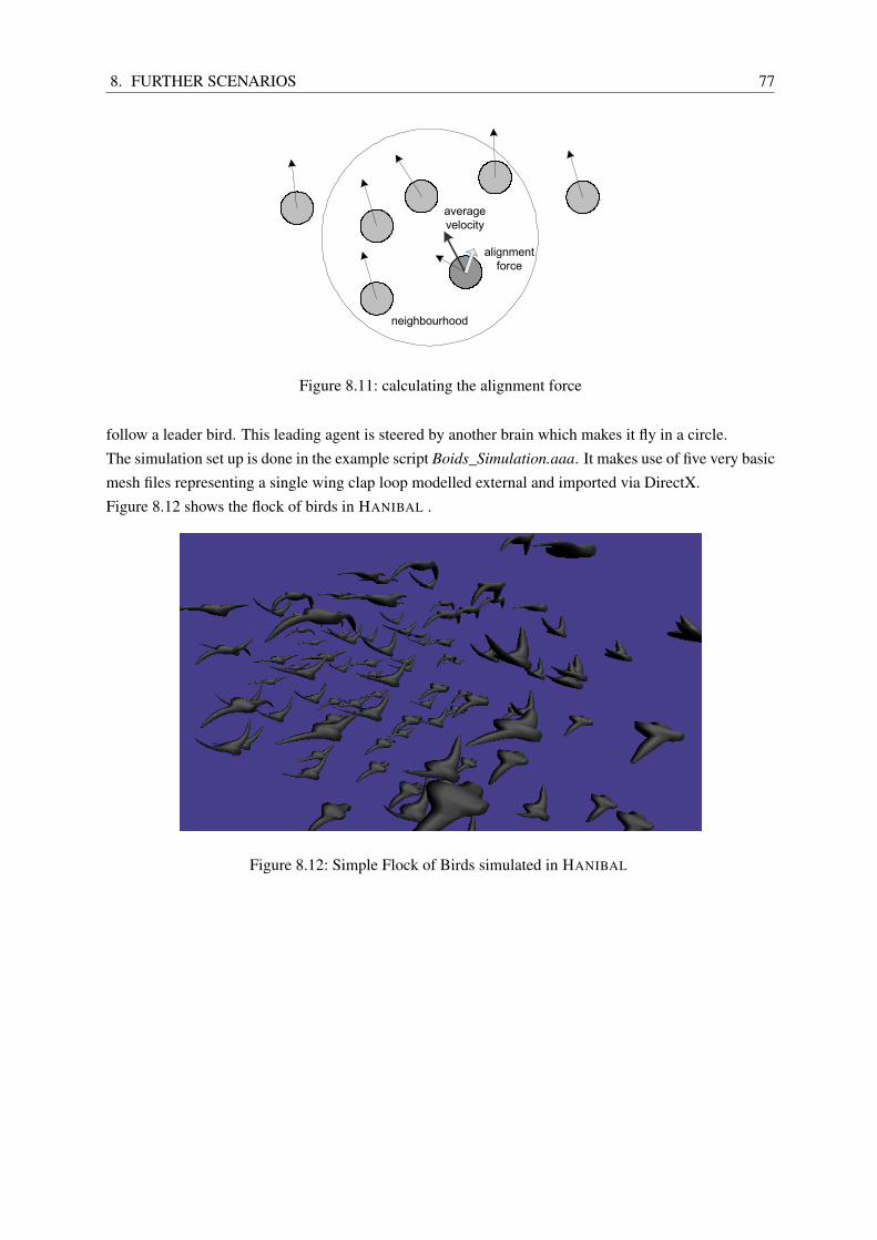
In the mid eighties Reynolds [15] published his article about modelling natural behaviour of flocks,schools and herds of animals. He designed a software called Boids which implements emergent be-haviour. This means, the complexity of the final animation arises from the interaction of individualentities. This is probably the best known approach to the facilitation of agent based systems in animationso far.Reynolds motivates his approach by saying that "[t]ypical computer animation model[s] only the shapeand physical properties of the characters, whereas behavioral or character-based animation seeks tomodel the behavior of the character. The goal is for such simulated characters to handle many of thedetails of their actions, and hence their motions." [15]Like a director in a theatre play the animator tells his actors what to do, but relies on their abilities toactually make things happen.But what do we actually mean when we talk about behaviour?In his implementation Reynolds used three simple steering patterns for the motion instructions of a singlebird, separation, cohesion and alignment. These three clearly defined forces result from the individualbirds observations of its neighbours and are applied to its own motion vector.What behaviour Reynolds described is quite simple to understand and can ( and had to, to be part of acomputer program ) be formulated in clear mathematical terms. Separation forces the bird not to crowdwith local flock mates. Cohesion on the other hand forces the bird to stay together with the flock. Align-ment ensures that the bird orients his moving direction with his neighbours to make all of them fly in thesame direction.We run the entire simulation with a few dozens of agents. What we see is a flock of birds behaving in avery smooth and natural way. We could see the same thing when looking out of the window. Althoughnot a single line of code says anything about the movements of a flock of birds the Boids actual behavelike one.What we witness is that "local interaction between individuals that follow simple rules may - on a muchlarger scale - induce complex behaviour and intricate patterns." [20]. Reynolds obviously found a simpleset of behaviour rules which emerges behaviour of a much higher order. We get back to a Boids imple-
4. CONCEPT OF BEHAVIOURAL ANIMATION 18
mentation with our animation system in chapter 8.2.Another popular example of emergent behaviour can be found in biology. The neuronal structure of anant or a termite is not complex enough to keep the entire construction plan of their highly sophisticatedmount structures or find and remember the shortest path between a food source and their nest. Never-theless the mounts do exist and everyone of us must have had a perfectly straight ant trail through thekitchen at least once.The quite astonishing solutions nature came up with are part of many scientific projects. For more infor-mation on other scientific research on "reverse engineering" of the behaviour of ants see [9].From Reynolds emergent flocking behaviour Vuik draws the connection to reality and points out that"whether our own super-complex society is also founded on a small set of simple principles, remainsan unsolved puzzle". For us this puzzle becomes part of the task to create a behavioural animation sys-tem based on interaction of individual agents. A system which enables us to design a set of behaviourrules which once put into action hopefully induct animations which meet the requirements of the givenproject.Brogan and Hodgins [6] proceed from Reynolds’ work and use similar control algorithms to steeringpatterns to dynamically control simulated characters. They concentrate on three different problems:steady-state motion, turning, and avoiding obstacles. The presented approach bases on physical anima-tion. It does not facilitate a library of pre-created animations, instead characters are build up as hierarchyof rigid body parts which are connected by rotational or telescopic joints.For calculating motions the behavioural simulation makes use of a locomotion control layer. This com-ponent performs physical calculations and tries to match movement desires coming from the behavioursystem with forces creating elaborate motion. The advantage of this approach is, that dynamically cal-culated characters make simulation outcomes independent from a limited graphic library. On the otherhand the physical modelling of realistic locomotion creates a heavy processing load and is not seldomvery difficult to achieve.Perlin and Goldberg [13] presented a very different approach with a system called Improv. This applica-tion is designed for the creation of real-time, behaviour-based, animated actors and is structured into twosubsystems.The first component is an animation authoring engine. It provides procedural techniques to create lay-ered, continuous, non-repetitive motions and smooth transitions between them.The second system is the behaviour engine which determines how a character interacts with other char-acters and the environment. This behaviour simulation is based on sophisticated rules governing howactors communicate with each other and make decisions.Both parts of Improv form a system which allows the "authoring [of] the ’minds’ and ’bodies’ of inter-active actors." [13]. The system provides a very simple scripting language, which supports the creationof scenarios not only by experts but people from a creative background.To provide controllable animation components Perlin and Goldberg extend the term of Degrees of Free-dom (DoF) beyond its common usage as a count of rotational and telescopic motion abilities of a certainjoint.An example would be an animator defining blended motions for facial animation. Lets assume each mo-tion blend is an interpolation between two different meshes of the same topology. Every blend can geta weight which defines its influence on the final shape of the face. Relating to [13] this value becomesa DoF for the character. DoFs for Smiling, Yawning or Wondering provide the freedom of creating a
4. CONCEPT OF BEHAVIOURAL ANIMATION 19
compound expression in a characters face.
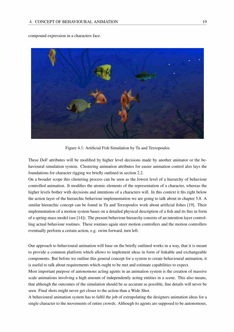
Figure 4.1: Artificial Fish Simulation by Tu and Terzopoulos
These DoF attributes will be modified by higher level decisions made by another animator or the be-havioural simulation system. Clustering animation attributes for easier animation control also lays thefoundations for character rigging we briefly outlined in section 2.2.On a broader scope this clustering process can be seen as the lowest level of a hierarchy of behaviourcontrolled animation. It modifies the atomic elements of the representation of a character, whereas thehigher levels bother with decisions and intentions of a characters will. In this context it fits right belowthe action layer of the hierarchic behaviour implementation we are going to talk about in chapter 5.8. Asimilar hierarchic concept can be found in Tu and Terzopoulos work about artificial fishes [19]. Theirimplementation of a motion system bases on a detailed physical description of a fish and its fins in formof a spring-mass model (see [14]). The present behaviour hierarchy consists of an intention layer control-ling actual behaviour routines. These routines again steer motion controllers and the motion controllerseventually perform a certain action, e.g. swim forward, turn left.
Our approach to behavioural animation will base on the briefly outlined works in a way, that it is meantto provide a common platform which allows to implement ideas in form of linkable and exchangeablecomponents. But before we outline this general concept for a system to create behavioural animation, itis useful to talk about requirements which ought to be met and estimate capabilities to expect.Most important purpose of autonomous acting agents in an animation system is the creation of massivescale animations involving a high amount of independently acting entities in a scene. This also means,that although the outcomes of the simulation should be as accurate as possible, fine details will never beseen. Final shots might never get closer to the action than a Wide Shot.A behavioural animation system has to fulfil the job of extrapolating the designers animation ideas for asingle character to the movements of entire crowds. Although its agents are supposed to be autonomous,
4. CONCEPT OF BEHAVIOURAL ANIMATION 20
they still have to be controllable.The more autonomy a character is supposed to have, the more work has to be put in environment set up,implementation of perceptive functions and behaviour design. It sometimes might be easier to hard wirea certain action than to tweak parameters of an entity to make it do what it is supposed to on its own.The application framework also has to be flexible enough to support a nearly endless range of applica-tions. It is not said with which ideas script writers and directors will come up. It is important, that -if it does not support a needed feature initially - it is adaptable and extendible to meet these needs in areasonable time and without loosing its usability for the animation designer.So how does our desired animation system look like?What we want is an application to design behaviour. This behaviour will be applied to certain entities ina simulated world.These entities will then act independently in the intended way. The world and all its components willbe presented as elements of a 3D scene with each element being seen as its current behavioural statedescribes.We want to make use of the capabilities of already existing modelling and animation procedures andfacilitate their results in this system. We want to be able to gain from other simulation approaches (asjust described) by including them via import of external modules. We want to be able to interact with theenvironment and control its components to achieve our desired results. We also want to use the outcomesof this process in a further production pipeline to support the production of our film.
Lets start shaping the outlines for a behavioural animation system created from scratch. It is not meantto be the only possible, nor the best approach to behavioural animation. It is sure, that there are manyother ways of designing such a system and therefore it should be seen as the basis for further studies anddevelopments in behavioural animation.What we try is to establish a common platform for matching different approaches to behavioural anima-tion by defining certain terms and fundamental structures they base on.These general design ideas are then put into the creation of a software package called HANIBAL , thereference implementation for the presented concepts. HANIBAL clearly has disadvantages to other avail-able software. It is not optimized for a real life production environment, but is supposed to provide animplementation example for described concepts and in this context deliver reasonable results.
Figure 4.2 shows a very generalized scheme for the structure of a behavioural animation system. Itcontains the two main responsibilities - Simulation and Representation distributed among the three keycomponents of such a system - World Simulation, Behaviour Simulation and Stage.
The responsibilities are clearly separated from each other. As a general concept of computer science,we want to distinguish between the data model holding the semantics of our simulation and the actualvisualisation of it. This concept can be found in software design as well as the architecture of clientserver systems.Any change in the data layer will force the representation layer to update its contents to give a consistentview of the simulation state at any time. At one point in the further explanations we will discuss thenecessity of the feedback channel violating this strict separation.
4. CONCEPT OF BEHAVIOURAL ANIMATION 21
RepresenationSimulation
Stage
Shape3Shape1
Shape4
Shape2Shape5
Behaviour Simulation
Brain1
Brain3
Brain2
World Simulation
Entity1
Entity3
Entity2
Entity4
Entity5
Translation Process
FeedBack Channel
Figure 4.2: concept structure for a behavioural animation system
We see that the behavioural simulation component is separated from the actual world simulation. Thisroots back to a concept Reynolds [15] already introduced with Boids which we are going to facilitate.From now on we are going to call the actual behavioural simulation components Brains. These brainscontain functions for performing autonomous agent behaviour. We will assume their behaviour functionis based on the concepts explained in chapter 3.A brain can become very complex and often uses a lot of system resources. Although we expect to haveseveral hundreds of agents in our simulation, it will only contain a few brains. Most of the agents willperform the same behaviour. This does not necessarily mean that they all do exactly the same, in case ofReynolds Boids we have a ratio of n:1 and still all the birds are acting independently.For efficiency and modularity reasons it will proof very useful to make the brains as independent as pos-sible from the actual agent performing the behaviour.We will get to the explanation of how the behaviour execution in an agent actually works in a bit.
We will call the agents in our world simulation Entities. As we just learned, such an entity does notcontain, but refers to the behaviour function and therefore the brain which it is supposed to perform.An entity also contains some kind of inner state representing its actual simulation appearance. It rep-resents everything which is to be and will always be known about the entity. Each simulation relevantinformation has to be kept in this state. Like the human genes it defines what the entity is.In case of a reflex agent implementation the state will only consist of its physical attributes like positionor size. In a model based agent it will contain more than that, e.g. memories and experiences the entityhas made in its lifetime.
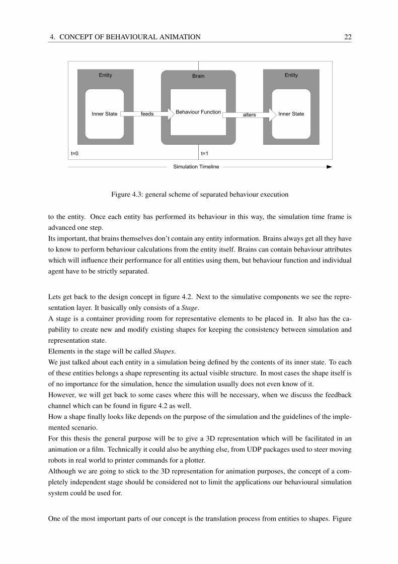
Figure 4.3 shows how a separated behaviour call will work. We see a section of two time slots on thesimulation time line. The simulation recieves a call to execute one calculation step. The entity at t=0passes its inner state to the brain which is assigned to it as its behaviour function.The brain performs the behaviour function on this set of values and writes the altered inner state back
4. CONCEPT OF BEHAVIOURAL ANIMATION 22
t=1t=0
Entity
Inner State
Brain
Behaviour Functionfeeds
Entity
Inner Statealters
Simulation Timeline
Figure 4.3: general scheme of separated behaviour execution
to the entity. Once each entity has performed its behaviour in this way, the simulation time frame isadvanced one step.Its important, that brains themselves don’t contain any entity information. Brains always get all they haveto know to perform behaviour calculations from the entity itself. Brains can contain behaviour attributeswhich will influence their performance for all entities using them, but behaviour function and individualagent have to be strictly separated.
Lets get back to the design concept in figure 4.2. Next to the simulative components we see the repre-sentation layer. It basically only consists of a Stage.A stage is a container providing room for representative elements to be placed in. It also has the ca-pability to create new and modify existing shapes for keeping the consistency between simulation andrepresentation state.Elements in the stage will be called Shapes.We just talked about each entity in a simulation being defined by the contents of its inner state. To eachof these entities belongs a shape representing its actual visible structure. In most cases the shape itself isof no importance for the simulation, hence the simulation usually does not even know of it.However, we will get back to some cases where this will be necessary, when we discuss the feedbackchannel which can be found in figure 4.2 as well.How a shape finally looks like depends on the purpose of the simulation and the guidelines of the imple-mented scenario.For this thesis the general purpose will be to give a 3D representation which will be facilitated in ananimation or a film. Technically it could also be anything else, from UDP packages used to steer movingrobots in real world to printer commands for a plotter.Although we are going to stick to the 3D representation for animation purposes, the concept of a com-pletely independent stage should be considered not to limit the applications our behavioural simulationsystem could be used for.
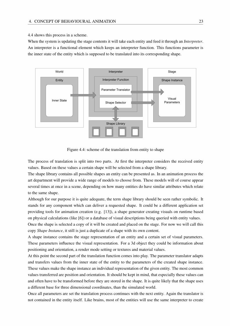
One of the most important parts of our concept is the translation process from entities to shapes. Figure
4. CONCEPT OF BEHAVIOURAL ANIMATION 23
4.4 shows this process in a scheme.When the system is updating the stage contents it will take each entity and feed it through an Interpreter.An interpreter is a functional element which keeps an interpreter function. This functions parameter isthe inner state of the entity which is supposed to be translated into its corresponding shape.
Interpreter
Entity
Inner State
Shape Instance
Visual Parameters
Shape Library
Interpreter Function
Parameter Translator
Shape Selector
World Stage
Figure 4.4: scheme of the translation from entity to shape
The process of translation is split into two parts. At first the interpreter considers the received entityvalues. Based on these values a certain shape will be selected from a shape library.The shape library contains all possible shapes an entity can be presented as. In an animation process theart department will provide a wide range of models to choose from. These models will of course appearseveral times at once in a scene, depending on how many entities do have similar attributes which relateto the same shape.Although for our purpose it is quite adequate, the term shape library should be seen rather symbolic. Itstands for any component which can deliver a requested shape. It could be a different application setproviding tools for animation creation (e.g. [13]), a shape generator creating visuals on runtime basedon physical calculations (like [6]) or a database of visual descriptions being queried with entity values.Once the shape is selected a copy of it will be created and placed on the stage. For now we will call thiscopy Shape Instance, it still is just a duplicate of a shape with its own content.A shape instance contains the stage representation of an entity and a certain set of visual parameters.These parameters influence the visual representation. For a 3d object they could be information aboutpositioning and orientation, a render mode setting or textures and material values.At this point the second part of the translation function comes into play. The parameter translator adaptsand transfers values from the inner state of the entity to the parameters of the created shape instance.These values make the shape instance an individual representation of the given entity. The most commonvalues transferred are position and orientation. It should be kept in mind, that especially these values canand often have to be transformed before they are stored in the shape. It is quite likely that the shape usesa different base for three dimensional coordinates, than the simulated world.Once all parameters are set the translation process continues with the next entity. Again the translator isnot contained in the entity itself. Like brains, most of the entities will use the same interpreter to create
4. CONCEPT OF BEHAVIOURAL ANIMATION 24
their shapes.
We now have a system to simulate behaviour of individual entities as part of a simulated world. Entitieswill be visualized via a translation process done by interpreters as shape elements of a stage.The only thing we didn’t talk about is the feedback channel. It provides the simulation with access to therepresentation layer. This could mean, that entities can access their corresponding shapes or brains coulduse the visual representation of the simulation for collision detection or visibility tests.The reason we introduced this feedback is to have animation response. Entities in a certain state will berepresented with animation clips. We don’t want the behaviour system to deal with the actual length ofthese clips. But for proper animation we do need this information to avoid interrupting animation loops.The feedback channel is used to transfer this information back to the behaviour simulation, which canapply state changes accordingly.We will get back to this problem once we introduced the details of HANIBALs implementation, whichwill be topic of the next chapter.Before we come to that we want to summarize the given concept and point out to the main characteristicswe tried to consider.A main concern of this structure is modularity. Modularity which enables us to exchange and advancesingle system components without violating the functionality of others. The established modularity alsoprovides a good base for the software design of the application.With modularity we achieve flexibility as well. Developments in artificial intelligence, further improve-ments of animation concepts, different data sources - the demonstrated architecture deals with all of theseuncertainties on a very abstract layer.
5. HANIBAL - A BEHAVIOURAL ANIMATION PACKAGE 25
5 HANIBAL - A Behavioural Animation Package
The last chapter described a concept structure of a behavioural animation system. In this chapter we aregoing to describe how this concept is actually transferred into a reference implementation. The applica-tion we present is called HANIBAL , somewhat relating to the ancient warlord commanding thousands ofhis men in the war against Rome.HANIBAL is supposed to demonstrate the working principles of the introduced concept and provides abasis for further studies and developments.It is not meant to be used in an actual production process, although its modularity provide a good startingpoint to adapt it for fulfilling the requirements of a production scenario.
First we want to talk about our choice of platform. HANIBAL is implemented in C# and the .NET 2.0Framework [2]. The decision to go with C# instead if C++ was made, because it provides a high levelcapability of compiling dynamic code and linking new modules into an application on runtime.This created the opportunity to get rid of any limits for the behaviour implementation, without changingany line of existing code in the core of the application. It fully depends on the behaviour designer whichfeatures of .NET, of third party modules and his own wits will be facilitated in an agents behaviour con-cept.This ability of dynamic code has been used further. To provide maximum flexibility extension modulesto HANIBAL can be imported on runtime and provide new elements for the simulation set up. Also newGUI elements, control features, agent types, world objects or interpreter structures become availablethroughout any simulation created with this package and fulfilling the interface criteria. The .NET ar-chitecture allows to implement these features in any language which eventually compiles to native .NETcode, e.g. VB.net, managed C++ or C#.For graphic output HANIBAL currently makes use of the Microsoft Managed DirectX SDK [3]. It fitssmoothly into the C# syntax and already provides datatypes and classes for handling and not at leastrendering 3D scenes on modern graphics hardware. Although most provided examples currently rely onthe presence of DirectX the entire structure of HANIBAL is designed to allow any other way of graphicaloutput as well.
5.1 Structure
A behavioural animation system is a complex structure of independently interacting objects. These ob-jects are of an arbitrary type and their functionality transparent to each other. This means we do not knowwhat kind of elements we will have in our system, nor how they work inside. The final system is like abunch of black boxes, some of them wired to each other, others acting independently.To provide room for these elements HANIBALs core component is the so called Workspace. Figure 5.1
5. HANIBAL - A BEHAVIOURAL ANIMATION PACKAGE 26
shows this workspace container and its common components.
Imagine the workspace as a hierarchy of the system components described in the last chapter. Again wesee the two responsibilities of Simulation and Representation. We find the world with entities and thestage containing shapes.Components belonging to each other - like SimulationEvents or GraphicObjects - are grouped under anexplicit container. This is mainly for keeping the workspace tidy and for supporting system tools work-ing on a certain element type.We will work through all the shown components one by one and explain how these elements functiontogether. We are going to show script examples of how to use them and explain the principles of certainprocesses in explicit schemes. The next chapter contains a step-by-step tutorial of using HANIBAL to setup a given scenario.
5. HANIBAL - A BEHAVIOURAL ANIMATION PACKAGE 27
5.2 Module and Namespace Structure
HANIBAL comes as an application system which consists of several libraries and tools. The most im-portant tool is HANIBALs main application called hanibal.exe. Another executable is the standalonebraineditor.exe for behaviour design. This application uses GNoI.dll, a little helper framework for edit-ing node based graphs.All core components of HANIBAL are grouped in the main system module core.dll. Features.dll containsfeature sets for setting up certain scenarios. We will talk about them later.All elements we are going to present now, are part of HANIBALs core. It facilitates another helper mod-ule named Crimson.dll which encapsules parts of Direct3D to provide easier use of meshes and textures.Figure 5.2 shows the relations between the module libraries and executables within the HANIBAL system.
core.dll
hanibal.exe braineditor.exe
features.dll
DirectX/ Direct3D Crimson.dll GNoI.dll
Figure 5.2: relations between module libraries and executables
Within the Core library exists a complex .NET namespace structure. These namespaces encapsulatesemantic groups of system parts and basically reflect the hierarchy of system elements visible in Figure5.1.
5.3 The Workspace
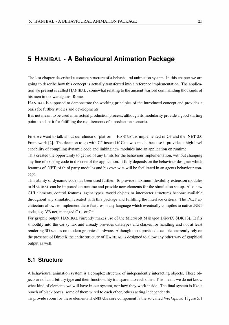
As already mentioned, the workspace is the container for every action taking place in the entire system.The workspace and all its components are separate classes inheriting from a class called Nameable.Figure 5.3 shows its UML class diagram.The workspace itself is designed as a singleton class. There will always be only one instance of it in theentire system. More on the singleton design pattern can be found in [8].
Nameable provides the structural functionality for building up the element hierarchy in HANIBAL . Thishierarchy is a directed, non cyclic graph structure, where each element can contain an indefinite amountof child elements.Usually the hierarchy will be three levels deep. Element controllers are children of the workspace andcontain actual system elements performing required tasks.
Figure 5.3: Nameable is the base class for all system components
Nameable also provides the ability to access workspace elements directly with a path name. Like a di-rectory path each item is referenced with its name, the separator for hierarchy levels is a vertical dash.Here are three examples of how to access objects by their full path name in a script.
Any element in the workspace hierarchy can be instantly accessed from the user interface. How to createown interface components for editing workspace elements will be explained in the appendix.
5.4 Property Concept
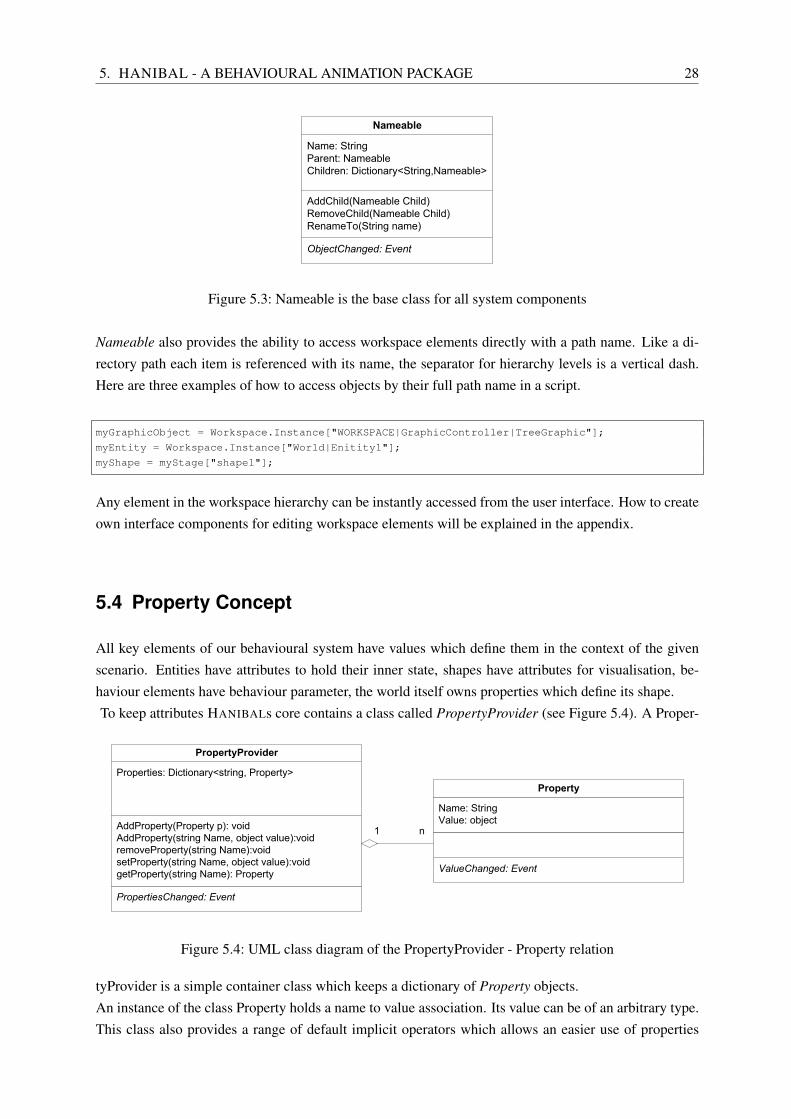
All key elements of our behavioural system have values which define them in the context of the givenscenario. Entities have attributes to hold their inner state, shapes have attributes for visualisation, be-haviour elements have behaviour parameter, the world itself owns properties which define its shape.To keep attributes HANIBALs core contains a class called PropertyProvider (see Figure 5.4). A Proper-
Figure 5.4: UML class diagram of the PropertyProvider - Property relation
tyProvider is a simple container class which keeps a dictionary of Property objects.An instance of the class Property holds a name to value association. Its value can be of an arbitrary type.This class also provides a range of default implicit operators which allows an easier use of properties
5. HANIBAL - A BEHAVIOURAL ANIMATION PACKAGE 29
when scripting.HANIBALs user interface provides a component which allows to edit properties of all common typeslike numerical or string values, bools and enumerations, as well as matrices and vectors of DirectX. It isdesigned to allow the implementation of other editors for user defined property types as well. More onthat topic can be found in the appendix as well.To access properties of a workspace object it is possible to feed an indexer on the PropertyProvider withthe properties name. The following code demonstrates different ways of reading and writing properties.
// accessing a property and its value
position = (Vector3) myEntity.Properties.getProperty("position").Value;
// normal indexer access
position = (Vector3)myEntity.Properties["position"];
// using an indexer of the entity class
position = (Vector3)myEntity["position"];
// using an indexer and an implicit cast operator of the entity class
position = myEntity["position"];
For a real production environment property access via a C# collection class might end up being too slow.For systems with a high amount of property access it could become useful to exchange the concept ofproperties and property providers in entities with a hard wired approach.New types of Entities would be written as separate classes inheriting from the class DynamicEntity andadditional Properties would be created in them straight away. This would clearly increase the perfor-mance of behaviour calculations on these Entities.For now, HANIBAL is to be seen as reference implementation providing maximum flexibility and mod-ularity. We decided to allow the user to add and manipulate the property structure of all workspacecomponents on runtime. Dedicated tools have been created to allow a quite comfortable access to allthese values. In a later version of HANIBAL it could be thought of extending dynamically compiledelements to all parts of the workspace by using the .NET reflection capabilities.
5.5 Dynamic Module Bindings
HANIBALs capability of loading dynamic link modules (dlls) on runtime has already been mentionedseveral times. Before we start digging deeper in the functionality of the simulative system, we want toexplain how to import .net dlls and use classes from them at runtime.To hold bindings the workspace contains a DLLBindingController (see Figure 5.1). It again is a basiccontainer class holding all current bindings as its children.The class DLLBinding contains the actual binding information in form of a system path to the boundmodule file and a list of namespace pathes from this module which are to be included in the dynamicscript compilation process. Figure 5.5 shows the relation between bindings and script engine in a scheme.
Once a binding is loaded into the system, any type defined in the scope of the given namespaces fromthis module can be used in the script process.Therefore the binding set up will always be the first thing to be executed when loading a simulation.To ease the process of setting up bindings and to avoid having to import all modules every time we are
Namespaces: Crimson, Crimson.DirectX ... Binding information Compiler
Script1
Script code
Compiled Script1
Assembly
Figure 5.5: dynamically loaded bindings are used for compilation of script objects
designing a new simulation, the user interface of the DLLBindingController contains a method to exportall its currently loaded bindings into a script.Executing this script will import all loaded modules and namespaces into the system.An excerpt form one of these scripts looks like this:
createBinding("Crimson.dll","Crimson.dll", new string[]{"Crimson", "Crimson.DirectX"});
createBinding("System","System.dll", new string[]{"System", "System.Collections"});
createBinding("Core.dll",@"Core.dll", new string[]{"AAA.Core.Util", "AAA.Core.Universe"});
5.6 Scripting
One of the most important parts of HANIBALs core is its ability to execute arbitrary script objects basedon C# as scripting language. We already used a few examples and all of the following explanations willalso contain script snippets for demonstration purposes.HANIBAL can be run completely without a user interface. All interface components eventually executedynamically compiled script commands, respectively execute commands directly from the ScriptEnvi-ronment.The ScriptEnvironment is a class containing all of HANIBALs explicitely designed system commandsas static methods. A list of commands which are present in the script environment and how they aresupposed to be used in the system can be found in the automatically generated software documentation.The reason for using C# as scripting language is that it provides an easy to understand syntax, a verypowerful framework and good documentation. For more details on the languages syntax please have alook at the official reference [1].HANIBALs script engine supports several kinds of script objects. The most common are instances of thegeneral class Script. They implicitly contain the user defined dynamic code to be executed as well as areference to the already compiled and cached assembly if present.The class Script itself is only container for an instance of ScriptObject and makes the script accessiblewithin the Workspace. The ScriptObject class inherits from ScriptEnvironment. This class actually holdsthe code information and is used for the creation of dynamically compiled objects. The reason for thisquite elaborate structure is, that C# - for good reasons - does not support multiple inheritance and weneed Script to inherit from Nameable to make it part of the workspace.On execution the static class ScriptCompiler is called to assemble a full class source code out of the userdefined code snippet, binding information from the BindingController and a pre-defined class frame.
5. HANIBAL - A BEHAVIOURAL ANIMATION PACKAGE 31
The assembled class code is compiled and the assembly returned to the script object. A caching mech-anism prevents the system to recompile unchanged code and refers directly to the assembly. The scriptobject then executes the dynamic code in the assembly.This process is shown as a scheme in Figure 5.6.
ScriptCompiler
Compiler
Nameable
ScriptEnvironment
System Commands
BindingController
Bindings
Script
ScriptObject
User Code
Cached Assembly
Code Frame
Used Namespaces
User Code
assembled class code
Execution
Figure 5.6: compilation and execution of a script object
Other script types used within HANIBAL are made for special purposes. The Brain components Activityand Condition contain dynamic script objects which actually perform the actual behaviour calculations.The SimulationEvent is used to perform certain simulation events placed on a timeline. The principle ofhow these special purpose objects work is the same as with the general script object.Next to script objects being held in the system HANIBAL provides a simple command prompt for theexecution of any given C# code in the context of the script environment. In case of a compiler error orruntime exceptions feedback is given on the console.
We have now covered the fundamental features which HANIBAL uses to base the simulation and repre-sentation layer on. The next section starts do show how the behavioural design is implemented, continu-ing with world set up, defining of interpreter functions and eventually creating visual output.
5.7 Brains, Activities and Conditions
Section 3.5 contained elaborate explanations about the classification and design of finite state machines(FSM). HANIBALs behaviour implementation supports the design of arbitrary kinds of state machinesby providing a very generic concept of automaton construction.The decision to go with FSMs in behaviour design is clear. It is the most common approach to behaviourdesign, well studied, easy to implement and allows a high modularity.Figure 5.7 shows the scheme of a state machine as it occurs in HANIBAL including the relations betweendifferent classes of the core framework.
The class Brain is the container for all components of a certain behaviour implementation. To talk aboutthe actual behaviour execution we are first going to introduce these components.States are modelled by instancing the class State. It contains the logic for performing an entities actions.These actions are based on the class Activity and hold user created scripts which contain the implementedaction. Activities can be of three different types depending on the moment of execution: OnEnter, On-
5. HANIBAL - A BEHAVIOURAL ANIMATION PACKAGE 32
Brain
State
State1
OnEnter: Activity1
OnPerform: Activity2
State2
OnPerform: Activity3, Activity4
OnLeave: Activity5
Condition1 Condition2
Condition3
StopStateCondition4
Transition ActivityConditionBrain StopState
Figure 5.7: scheme of a state machine with HANIBAL class relations
Perform, OnLeave.The following code snippet shows a simple activity script performing some random behaviour. The ac-tual user script is marked separately. The method header is only shown to demonstrate how the entiredynamic code will look like, it is not supposed to be part of the user script. The actual implementationdiffers from this example because of the execution of dynamic code but semantically it does the same.
public void perform(Entity E)
{
// begin user script
Machine.calculate_physical_attributes(E);
int sensor_value=E["sensorA"];
int result=0;
if (sensor_value>0) result = Machine.doThingA(E);
else result = Machine.doThingB(E);
E["machinestate"]=result;
// end user script
}
In this example we also see the usage of a feature set called Machine. We are going to talk about featuresets when we cover design concepts for the construction of brains in HANIBAL .State changes are modelled with objects of the type Transition. They contain instances of the Conditionclass which provide functionality to design scripted expressions which can be evaluated by the system.A transition can hold several conditions defining the value of its evaluation. To demonstrate how a con-dition script could actually look like, the following code gives an example. For better understanding italso contains the method header, which mustn’t be in the actual script used in the system.
public bool evaluate(DynamicEntity E)
{
// begin user script
bool result;
if (E["temperature"]>99.8f) return true;
5. HANIBAL - A BEHAVIOURAL ANIMATION PACKAGE 33
else return false;
// end user script
}
Sometimes a state is needed, which marks the end of the behaviour calculation process. For this purposethe explicit StopState class can be used, which will cease the entity to perform behaviour. A StopStatecannot contain any activities. It is also used for building up hierarchic brain structures. We will discusshierarchic state machines later in this chapter.
Figure 4.3 in chapter 4 shows the process of behaviour execution we developed for the concept of ourbehavioural animation system. When implementing HANIBAL we tried to stick as close as possible tothis principle.When the system performs a simulation step, the world object runs through all its entities by selectingone of them and making it execute its behaviour.At this point the strict separation between entity and behaviour function comes into play. The selectedentity uses itself as a parameter to call the perform( Entity e ) function of the state it currently is in.The scheme in figure 5.8 shows what happens next.
t=0
t=1
State
Entity
Entity
Transitions Conditionsevaluate
result
evaluate
Simulation Tim
eline
perform
alter properties Activities
change current state
perform
result
Figure 5.8: behaviour execution on state level
After the entities perform call to the state, the state itself executes all its OnPerform activities on the givenentity. The activities themselves get the entitiy handed over as function parameter. Entity attributes areaccessed and modified from the activity. This is the way the inner state of an agent changes.After performing the activities the state evaluates all transitions leaving from him. Each transition passesthe calling Entity over to its conditions, which evaluate the entities parameter and return true or false.Based on the outcome of the accumulated results from its conditions the transition returns true or falseback to the state.If the evaluation has been successful the state executes its OnLeave Activities on the given Entity. Thenit changes the current state of the entity to the end state of the successfully evaluated transition. This newstate is called to perform its OnEnter activities.If there is more than one transition with a positive evaluation, than the system decides on the priority of
5. HANIBAL - A BEHAVIOURAL ANIMATION PACKAGE 34
the transition. This priority is a property of the transition class and per default set to 1. The transitionwith the highest priority will be followed.This is the end of the behaviour execution. The World object selects the next Entity and continues in thesame way as just described.
Design Criteria
With the given tool set there are many ways of creating all kinds of state machines. We are going to talkabout two of them, which might suit our purpose best.The first approach is a completely dynamic script based one. All activity and condition logic is writtenas script performed by the related objects. This could have been done in the Brain Editor or directly inthe brain script.The Brain editor is a WYSIWYG application for designing Brains in HANIBAL . It is possible to createstates, link them with transitions, add activities and conditions and define dynamic scripts being executedwhen the brain is actually in use. In the end the editor exports the entire brain as a script file which will- once executed - create the brain designed in the workspace.The advantages of this process are, that all components can be designed with the provided tools and alloweasy and fast change of script code for behaviour design. The disadvantages are, that often code elementshave to be repeated and the brain script becomes more and more complex the bigger the brain gets. Thecompletely script based way of designing brains is recommended only for prototyping purposes.
When designing full scale production quality brains, it is very useful to make use of Feature Sets. Featuresets are classes dedicated to support the scripting process for a certain scenario. They contain only staticmethods which are used in scripts and mostly called by passing over the calling Entity and the Worldobject. This gives the method the ability to work with entity and world attributes.Remember the script example from the activity. It used a feature set called Machine. Machine is asimple class which is linked to the system on runtime. It contains methods which model sensorial inputand attribute modifications on a higher level.Instead of digging into entity and word properties, the behaviour designer writing the actual brain scriptnow uses methods like DoFeeding() or IsThereSomethingICanEat(). He does not have to deal with lowlevel attribute operations between world and entity which would eventually mean the same thing butwould be modelled with a much more complicated code.Feature Sets allow to split the work in to teams. One team models the world and world based methodsin a feature set and the other team creates the actual behaviour based on these functions. The more highlevel methods are available, the easier it gets to define behaviour activities and conditions.The most extreme case would be, if every activity and condition would only consist of a single callexecuting a method from the feature set which is doing the actual job. This is sometimes quite useful,e.g. when the behaviour designer is very familiar with programming syntax and the final brain does nothave to be modified a lot.In the demo-applications belonging to HANIBAL all different levels of feature set use are present.
Feature sets also cater for modularity and reuse of behaviour code. Some of them coming with HANIBAL containvery basic behaviour functionality which can be reused in different scenarios. They can be found in the
5. HANIBAL - A BEHAVIOURAL ANIMATION PACKAGE 35
Features.dll, which is linked into the system per default.An example is Steer, a feature set which provides methods for applying Reynolds Steering patterns forAutonomous Characters [16] to agents in a simulation. As long as an Entity contains the needed parame-ters for the application of a feature set, it will be able to make use of these already written and debuggedmethods.Although HANIBAL is not meant to be optimized in terms of system performance, the use of feature setscan also increase the speed of a simulation calculation. Any common principle of code optimisation canand should be facilitated within a feature set. The methods the designer uses are transparent in theiractual implementation and more code complexity wouldn’t hinder behaviour design.More on the use of feature sets will occur in the next chapter, when we actually set up a given demoscenario step by step.
5.8 Hierarchic Brains
When designing behaviour with the given tools we found, that our designed process of autonomous de-cisions very often implies a certain hierarchy.On the highest level very general decisions have to be made, e.g. what mood is the agent in, what doeshis emotional system tell him to do. Imagine the battle scene example we used in chapter 3. The mostgeneral decision a knight will have to do is, if he is joining a fight or running away.On the second level it becomes a more detailed when the agent has to select which actual actions he isgoing to perform to achieve his first level intention. How is our knight going to escape, in what way ishe going to attack.This structure has been named and further developed in a concept about autonomous agent architectureby Bratman, Israel and Pollack [5]. They introduced the notion of a Believe, Desire, Intention (BDI)model, which shapes the structure for autonomous decision making. Relating to their work Beliefs rep-resent the informational state of the agent. Everything the agents knows, remembers and assumes aboutthe world and all its contents forms his beliefs and is implicitly or explicitly contained in the inner stateof the agent.The agents Intentions are his deliberative state. It contains, what the agent intents to do, therefore ageneral tendency towards a certain behaviour.Desires (sometimes also called goals) are the actual objectives of an agents behaviour and stand for hismotivational state.Bratman et. al. delve into the very details of planning and decision making and provide important foun-dations for the development of autonomous agent systems. We are just going to take a loan on theirfundamental notion and facilitate this when we try to extend our finite state machine model.By introducing another type of state we enable the current behaviour implementation to support hierar-chic state machines.The class MetaState inherits from the class State and can be interlinked with Transitions in the same wayas other states.The difference is, that the behaviour execution of a MetaState will result in the calling Entity to startperforming behaviour of another brain associated with that state. This state change is modelled with ahard wired OnEnter Activity and is completely transparent to the system. This means, the state change
5. HANIBAL - A BEHAVIOURAL ANIMATION PACKAGE 36
from another state to a meta state will be performed like a state change from another state to the startstate of the linked brain.With this behaviour a MetaState element encapsulates an entire brain.The behaviour execution of the entity will continue with the brain in the lower hierarchy until it runsinto a stop state. At this point the entity will jump back into the upper level brain. To keep track of thecall hierarchy an entity actually contains a call stack to represent its current state. The topmost elementalways is the current state of the brain the entity is in. When changing brains, states get pushed onto andpopped of the call stack.A MetaState must only have a single unconditioned Transition leaving from it. This will lead the entityback into the normal behaviour execution. Figure 5.9 shows the process we just described in a scheme.
Brain2 (Level1)Brain1 (Level0)
State1
State2
MetaState1State1
State2
StopState1
OnEnter OnEnter
push Brain2 – Startstate (State1) on Callstack
Linked Brain:Brain2
pop current state Brain2:StopState1 from
Callstack
Figure 5.9: scheme of a simulation step across a MetaState (both ways)
The possibility to interlink brains creates a whole range of new opportunities in behaviour design but - aswith all good things - has some problems travelling with it as well. We strongly recommend that brainswill only be interlinked in a clear non-circular way.Of course it is possible to create brain networks which are as complex and connected as a common FSMas well. The resulting behaviour will be unpredictable and possible performance loss due to executionloops up to entire application faults might occur.To give an idea what our intention in introduction hierarchic behaviour designs is, we will briefly extendthe battle scene scenario mentioned earlier.We want to create the brain of a knight. As we all imagine a typical knight, he has three things he willdo in his life. He wants to protect his king, he wants to fight enemies threatening his kingdom and hasthe wish to stay alive whenever possible.These three goals are pretty general and we will call them the knights intentions.The scenario places our knight into the forest right next to his king. Whatever intention the knightchooses, he will need clear goals (or desires) to fulfil them, something he can do. Lets assume hechooses to defend his king. He could start patrolling the area, looking for enemies. In case of an attackhe would bravely join the fight. There would be no option of escape, he would defend the king as longas he is alive.This is the second level of the knights behaviour.What a behaviour designer would have to do, is to actually model all of these goals by defining someclear actions. Actions could be still complex like Approache Enemy, Hit Enemy with Sword or simpler
5. HANIBAL - A BEHAVIOURAL ANIMATION PACKAGE 37
behaviour Turn around or Walk next to the King. This is the third level of the knights behaviour.Figure 5.10 shows the presented scenario in a scheme.
Decision Process Decision Process Level of ActionLevel of Intention Level of Goals
Escort King
Defend from Enemies
Patrol Area
Evade Enemy
Attack Enemy
Seek Enemy
Look for Enemy
Run away
Guard
Fight
Escape
Wander Around (Patrol)
Accompany King
Hit Enemy
Defend against Hit
Approach Enemy
Look Around
Run Away
Figure 5.10: a battle scenario scheme showing different levels of behaviour
What we see is, that intentions are clearly modelled by uniquely defined goals. Decisions made on theintention level will lead to the execution of behaviour on the second level.Goals themselves are modelled out of something we could call something like an action library. Theaction level consists of all performable behaviour modules the agent is capable of. These actions aresequenced in a certain order by decisions made on the second level to make the agent perform behaviourfor the purpose of fulfilling a certain goal.The given behaviour hierarchy is implemented in a structure of brains and sub-brains. Every actionshown will be created as an extra sub brain on a fourth level of behaviour execution. Every goal is aseparate brain on the third level, containing links to the action brains on the level underneath. Intentionsare brains on the second level of behaviour. They contain calls to sub brains of the third level and decidewhich goal will be performed to support which the intention they stand for. The highest level is a superior"master"-brain which interlinks the agents intentions.The number of states to represent a behaviour decreases, the higher we get in our hierarchy. The semanticscope, the weight of the decisions made increases towards the top of the hierarchy.We actually do not deal with a clear tree structure. In our example actions will be used out of differentgoals and therefore in a changing context. This has to be considered when designing these action mod-ules. In case we do really need some special behaviour element, we still can always create it and onlyuse it in relation to one goal.This approach to behaviour design caters for the modularity of the entire system structure on behaviourlevel. Certain actions can be reused, complex behaviour models consisting of many intentions and goalswill make use of the same action level elements.
5. HANIBAL - A BEHAVIOURAL ANIMATION PACKAGE 38
This does not only decrease the workload. It allows to start behaviour design on a very high level, bytalking about what an agent is actually supposed to do. Later these intentions will be refined into goalsand eventually implemented in actions.
We have now covered the aspects of behaviour design and implementation with HANIBAL . We are nowgoing to talk about the realisation of the environment simulation.
5.9 World and Entities
The implementation of World and Entities in HANIBAL follows the presented concept very straight for-ward. The class World provides container functions for keeping the environment actors and methods forperforming simulation steps on them.All entities contain a PropertyProvider to hold an inner state. This inner state has to contain all informa-tion which is and will ever be known about this entity in the simulation process.Due to the fact, that there are no certain access rules for properties, technically all this information ispublic to any other part of the simulative system. Which properties are actually accessed by other enti-ties is a designers decision.
The world contains three kind of Entities, each of them inheriting from the class Entity. This base classcontains the common functionality like properties of any entity used in the system. Figure 5.11 showsthe three types and their relation in an UML class diagram.
Figure 5.11: UML class diagram of the Entity classes
Objects of the type StaticEntity are supposed to represent elements of the environment, which are notsteered by behavioural simulation, e.g. trees or other obstacles. They are not supposed to be solely used
5. HANIBAL - A BEHAVIOURAL ANIMATION PACKAGE 39
for graphic representation. In general Entities should not be used to model anything else than simulativecontent. Unless an item is somehow important for the simulation process - as simulation influence orother content for behavioural interaction - it should be added in further production steps and not in thesimulation.Although it is not a real part of the behaviour simulation, a static entity contains a single state. This stateprovides the opportunity to perform some simple attribute calculations during the simulation progress.The activities attached to this state will be performed once every simulation step.The more common and surely more interesting type are instances of the class DynamicEntity. Theseentities are the agents of our simulation. They contain a reference to their related brain as well as a callstack for keeping track of their current simulation state.There is actually nothing else to say about a dynamic entity on its own. The interesting part is the processof interaction with other system components which we will cover shortly.For an agent participating in the simulation static and dynamic entities are the same, because all the agentsees is the set of properties provided by the other entity. These properties define its entire inner and outerappearance and are the basis for the agents behavioural decisions. Which way these attributes are keptand modified is of no concern.This transparency also allows to implement completely different types of entities driven by any kind ofstructure underneath. As long as it keeps the attributes accessible to others, any other agent will be ableto interact with them.
As a side note we briefly want to talk about a default property all static and dynamic entities have hardwired into their code. It is called In-State-Counter (in the system short named ISC) and counts the num-ber of ticks an entity is in its current state. On every state change this counter is set back to zero. Thiscounter is used for timing and visualisation purposes. How this is actually done will be explained furtheron.
The third kind of entities are of the type ControlEntity. These elements are supposed to provide extendedcontrol features for animators and simulation designers. They are part of the World system because otherentities will have to interact with them and for debug purposes it is useful to have them appear in thesimulation rendering. The final simulation usually won’t show any of them.Chapter 7 will deal with these objects in detail.
5.10 Entity Emitting
An important need for the simulation is the actual way of how entities are placed in the world.The approach used in HANIBAL is taken from common particle systems - Emitters. Using a certainmethod of placement Emitters are objects which will add a specified amount of entities of a certain typein the world.Objects of the general type Emitter hold a public list of positions which can be filled by a script, byvertices of a mesh or a control entitys’ output (more on the last one in chaper 7). For the purposes of this
5. HANIBAL - A BEHAVIOURAL ANIMATION PACKAGE 40
thesis this is flexible enough to create a wide range of applications, but other types of Emitter implemen-tations are possible and can be included in the system via a DLLBinding.
An important feature for the emitting process is the variety of the created entities. The currently providedEmitter only places entities with equal properties at different positions in the scene.Lets say for our battle scene we might want a somewhat creative emitter, varying entity properties andtherefore the behaviour parameter, probably even the final representation of an entity in the animation.We do not want all knights to look the same. We want knights with different armor, strenght, stamina orfighting abilities.This variety could be created when emitting the entities in the world. The demo-simulations used anotherway for generating this entity variations.The behaviour simulation itself contains a start state with an OnEnter-Activity which creates all neededproperties in the entity and fills them with corresponding values. These values are created randomly.Therefore each entity placed in the scene will run through this activity and get the parameters it needsfilled with a unique set of values.The disadvantage of this approach is, that it is script based and cannot be controlled from the userinterface. Further developments based on HANIBAL could provide support with that.
5.11 GraphicObjects and the Stage
So far we have covered the part of HANIBAL responsible for setting up and running the Simulation. Nowwe are going to have a look at the representation of the simulated content and eventually talking in depthabout the translation process from the one to the other.First we have to introduce the components which are involved in this process, so the following expla-nations might demand some patience until the description of the actual processes will make things clearer.
In Figure 4.2 we see that the respresentation layer consist of a stage containing shapes. The same itemscan be found in HANIBALs core.A class called BasicStage provides a container which holds all representation items for the visualisationof the simulation. Only its contents will be rendered and displayed on screen.All visible elements are objects of the type Shape or its descendants. As we established in chapter 4,shapes are selected from a shape library and contain visual parameters for the rendering of individualentity representations.When implementing HANIBAL this structure remained semantically the same, but now differs a bit in thedetails. The Shape class itself now only contains what all shapes have in common. It therefore owns aPropertyProvider holding information about how the shape is going to be visualized. Shapes also containa reference to the entity they represent.The actual look of the visual element which was to be chosen from the shape library comes from a dif-ferent type of object called GraphicObject. Each shape contains exactly one reference to such an object.This reference points to one element of the shape library mentioned in the concept. In HANIBAL it isa library of graphic objects being called GraphicsController. This container holds all available display
5. HANIBAL - A BEHAVIOURAL ANIMATION PACKAGE 41
elements loaded in a scenario.Currently HANIBAL provides three types of regular graphic objects (we do not consider the type of Con-trolGraphicObject at the moment, because they belong to a different semantic category and are explainedlater).Each GraphicObject instance holds local space transform information and a view mode and is capable ofexecuting the necessary render calls to visualize itself. To consider the actual shape it is going to render,the render call passes this shape down to the graphic object which uses the contained world transforma-tion values for rendering.The three currently common types of graphic objects (GO) are XDummyGO, XSimpleMeshGO and XAn-imatedMeshGO. Figure 5.12 shows them in a scheme.All of these GOs base on DirectX - therefore the X in the name - and a little helper framework calledCrimson. We developed Crimson to provide classes for easier loading and drawing of meshes in Mi-crosofts .X format.XDummyGO is a graphic dummy in form of one of the DirectX default shapes (Torus, Sphere, BoxTeapot). It can be used for debug purposes or showing Entities whose graphic representations aren’tavailable yet.
XDummyGO
DummyTypes
XSimpleMeshGO
SimpleMesh
XAnimatedMeshGO
Mesh0
Mesh2 Mesh3
Mesh1
Frame Index
0123456
0121231
LoopLoopType
Figure 5.12: the three common types of graphic objects
The class XSimpleMeshGO encapsulates a single DirectX-Mesh file. It holds reference to the originalfile and draws it on a render call. It uses the files textures and materials by the help of Crimsons Texture-Manager class, which ensures, that no texture is unnecessarily loaded twice into the system.More complex and used all over the demonstration scenarios provided with HANIBAL is the type XAn-imatedMeshGO. This GO implementation contains a list of meshes and a lookup table of mesh indices.On render time the graphic object will take an Entities ISC (see section 5.9) and uses its value to do alook up in the index table. It then picks the related mesh and returns it for drawing.An instance of XAnimatedMeshGO can run in different LoopTypes (None, Loop, PingPong) which definehow an animation will be performed if the ISC exceeds the length of the index table.Just by using these three simple types of graphic objects it is already possible to set up proper behaviourbased animations. The use of other GOs for importing various kinds of file formats and clip types can beachieved with additional bindings of user implementations.
5. HANIBAL - A BEHAVIOURAL ANIMATION PACKAGE 42
5.12 Translation Process and Render Call
The process of rendering the contents of a simulation run in HANIBAL is split into two parts. The firstpart is the creation and update phase of the shapes within the stage, what we are going to describe astranslation process. This phase is executed after every simulation step.The second part is the actual rendering process and occurs whenever the application wants to refresh thesimulation view. We will call this phase the render call.Figure 5.13 shows the translation process as it is modelled in HANIBAL . After a simulation step theworld forces the stage to update all its contents. This means to create shapes of new entities and updatethe values of already existing ones.Every entity knows - next to its inner state - the interpreter group it belongs to. Each of these interpretergroups has one actual Interpreter assigned to it. The stage selects the interpreter based on the interpretergroup of the entity and uses it for the translation process.Each interpreter provides a method called interpret(Entity E, Shape I). Each entity and its correspondingshape are passed to this method, which deals with the provided parameters in two ways.
Interpreter
DynamicEntity
Inner State
Shape
Visual Parameters
GraphicController
Interpreter Function
Parameter Translator
GraphicObjectSelector
sele
ctio
n
World Stage
creates and updatespassed on to
Interpreter Group
GraphicObjectassigns reference
knows
InterpreterController
refe
rs to
is us
ed
Figure 5.13: the entity to shape translation process within HANIBAL in a scheme
First it uses the entitys properties to select a GraphicObject from the GraphicController and assigns itto the shape. Secondly it calculates the visual parameters (e.g. the world transformation matrix) of theshape.HANIBAL currently provides only one actual Interpreter implementation inheriting form the base class.The class StateDependentInterpreter provides the capability to select graphic objects for shape renderingdepending on the state the referred entity is in.This relation is modelled with an associative table which contains a state name-graphic object relation.Remember the battle scene example. When the knight is in the state Run he would be represented with agraphic object containing an animation clip showing a 3d model of a running knight, in a state SwordHitit would be a clip of the knight using his sword, and so on. This way the visual representation of the
5. HANIBAL - A BEHAVIOURAL ANIMATION PACKAGE 43
agent bases on the state names of the elements on level of action (see Figure 5.10).All demonstration scenarios provided with HANIBAL use this type of interpreter. It is a very basic ap-proach to the translation process, but is very flexible and comes up with good results. Other interpretertypes can be imported into the system via module bindings.After performing this process of translation for all entities contained in the simulated world the systemis ready for the render call to come.On a render call the stage iterates through all contained shapes and call the render function of the relatedgraphic objects. The graphic objects will apply their world transformations and render their visuals theways they are designed. HANIBALs presented default GOs render their contents directly into the pipelineof Direct3D.
5.13 Feedback Channel for Animation Response
In our concept we also introduced a feedback channel to enable world simulation to get some informationabout the contents of the representation layer.In HANIBAL each entity holds a reference to its Shape on the stage and can therefore access this shapes’attributes. The most common case will be animation response, when the entity needs to check if ananimation clip is currently at the end of a loop or not. This is important to keep clips from being cut offand enables us to avoid jerky transitions.For this purpose HANIBALs Shape class contains a property PeriodMeasue which evaluates the Graph-icObject the shape contains. If this graphic object is animated it calculates the measure of a value between0 and 1. The higher the value, the better the measure, the closer is the animation to a period point, whereit loops. An example for the use of the PeriodMeasure can be found in chapter 6.Other applications of the feedback channel could be visibility checking by tracing a ray through realstage geometry or collision detection.
5.14 Simulation and Events
An additional feature of HANIBAL , which is not directly described in the concept is the simulationtimeline.The workspace contains an object of the type Simulation. This object is container for SimulationEventinstances. Simulation events contain script code which is executed at a certain point in time with agiven periodicity. The entire event set up of the timeline can be done with the user interface and also beexported as a script for later use.This way the designer can trigger certain events on runtime.
For now we have covered all of HANIBALs system components on a very theoretical basis. The nextchapter will explain the usage of this system by explaining the set up of a complex scenario step by step.It will be supported by script examples and detailed explanations about behaviour design decisions madein this process.
6. HANIBAL IN PRACTICE - A DEMO SCENARIO 44
6 HANIBAL in practice - a demo scenario
Starting point for the creation of a behavioural simulation is to analyse the given task to find appropriateways of designing the scenario.For an animation production the simulation of fans in a soccer stadium is needed. While the actual soccergame is animated by hand, the entire crowd of fans is supposed to be created by the behaviour simulation.The designer wants to be able to steer the engagement of the crowd with a simple control feature. Fansare supposed to sit on their chairs, jump up if the game gets more exciting. They are supposed to expresstheir joy by clapping or waving.We want to approach the task by considering the given requirements and finding a good relation betweeneffort and achievable results. In the following section we will prepare a concept which will guide thelater creation of environmental and behavioural simulation.
6.1 Simulation Concept
People in a soccer stadium basically act upon two major influences. Most important role plays obviouslywhat is happening on the field. The second influence is the interaction between the people sitting closeto each other. These will be the two major elements we will consider in our behaviour set up.Of course there are more things going on in a stadium, e.g. rival groups, different fan blocks for the oneand the other team. Although all these considerations are of deep sociological impact, they won’t changethe outcome of our example animation a lot. For the simplicity of the example lets assume we do notneed them.Any crowd of people will look unnatural to an audience if we cannot avoid patterns and regularities inits entities behaviour. To meet that requirement most simulations will need some kind of dynamic inputfor modelling the element of chaos. What this influence looks like depends strongly on the animationscontext.In this demo case we are going to set up a little bouncing ball in the centre of the stadium. On one handit will be part of our game simulation to feed the fans with some sensorial input and on the other hand itwill provide some semi-chaotic influence on our crowd.We could also use a solely random value influencing our calculations, but this influence would be hardto relate to. It would also become harder to control which influence this value has on the simulation.The ball will bounce around in a box which is as big as the entire soccer field. We make the actualdistance between ball and fan a measure for the development of the fans excitement.The fan will also consider the excitement of a certain number of his closest neighbours. If his neighboursare happier than himself - which mathematically means the average of their excitement is higher than theone of the fan we currently look at - then the fan will get more excited as well.
6. HANIBAL IN PRACTICE - A DEMO SCENARIO 45
Perception
Seat Neighbours
Dummy Soccer Game Simulation
Inner State
Excitement
Stamina
recovers
cools down
feeds
influences
Actions
standing
sitting
clapping
waving
consume
need
predator/prey relationship
Figure 6.1: scheme of our soccer stadium simulation
Keeping track of excitement won’t be enough to fully simulate a fan. We also need something whichinhabits the excitement and prevents an activity overload. We introduce this feature by giving the fan astamina attribute.When the excitement increases, the fan will start to express his feelings by performing certain actions.This will consume stamina. If the stamina is low, the fan will cease his actions. The stamina will recoverincrease over time, as well as excitement will cool down if it is not fed by the environment. Figure 6.1shows the relation of stamina and excitement in a scheme.This behaviour reminds a bit of a predator-prey relationship, where the presence of one species influencesthe growth of the population of another species with a certain reaction delay. More on this topic can befound in [22].Now, that we have a pretty clear idea of how we are actually going to model our simulation, lets get intothe details of how we implement our ideas with HANIBAL .
6.2 Behaviour implementation
A Bouncing Brain
For our simulation we are going to create two different brains.At first we will deal with the behaviour of the bouncing ball. Considering the agent classification wediscussed in chapter 3, the bouncing ball agent will be of the simple reflex type. It has no inner state, nomemories, no goals. It simply reacts on what the environment looks like, it is moving in.The ball is meant to do only one type of action, bouncing around in a given collision geometry. Thismeans it will remain in one state for its entire existence, therefore the state graph of its behaviour is notvery exciting. The interesting part is the activity code performed in this state.The activity acquires the ball entities current position and direction and checks for a hit with the collision
6. HANIBAL IN PRACTICE - A DEMO SCENARIO 46
geometry provided by the world object. The collision box will always be a closed object. The ball issupposed to always be inside this box.The script starts to calculate the balls distance to the next hitpoint with the collision geometry. If the hit-point would not be reached within this simulation step it just applies velocity and direction to the entitiesposition.If we have a bounce within the current simulation step, we first move the entity straight to the wall andcalculate the bounced direction. We then move the entity its remaining velocity towards its new direction.
t=1
t=0
t=2
hitpoint
directio
nvelocity
Figure 6.2: scheme of a calculation step for the bouncing ball brain
Figure 6.2 shows a scheme of this collision calculation. From t=0 to t=1 the ball moves straight alongits direction with its given velocity. From t=1 to t=2 the ball hits the wall in the middle of the step. Itis moved to the hitpoint and its new direction is calculated. The remaining velocity is used to move theball into the reflected direction.The following script listing is the implementation of this behaviour. Please be aware that the script ex-amples syntax is sometimes simplified for better understanding and will look slightly different in the realsimulation files.
// acquiring Entity values
position=E["position"];
velocity=E["velocity"];
direction=E["direction"];
collision_mesh = WORLD["bouncer_box_mesh"];
remaining_velocity = velocity;
while (remaining_velocity>0)
{
// the collision object is convex and closed, there will always be a hit
distance_to_hitpoint = hitTest(collision_mesh, position, direction );
if ( distance_to_hitpoint > velocity_remainder )
{
position+=velocity*direction;
}
else
{
position+=distance_to_hitpoint*direction;
direction = calculateBounce(direction, position, cmesh);
velocity_remainder-=distance_to_hitpoint;
}
6. HANIBAL IN PRACTICE - A DEMO SCENARIO 47
}
// write back new Entity values
E["position"]=position;
E["direction"]=direction;
As long as the world contains a collision geometry object, we now have an entity bouncing within thisgeometries boundaries.
A Fans Brain
The fan brain is of much higher complexity. It is based on the model driven agent concept. The fanhas no discreet goal to achieve, but he will have an inner state modelling some physical attributes whichenable us to implement the concept we already developed.For this purpose we create a separate Feature Set and name it Fan2.Fan2 is a C# class containing helper functions for the brain implementation of the fan. We experimentedwith different set ups of this class and ended with a fully feature set based approach. This means, thatthe script performed in any activity of the brain only calls a single method from the function set whichcontains the actual script code. Due to the fact that environment and behaviour design were done by thesame person, this was the most effective solution (compare section 5.7).
Initialize
perform_initialize()
sit
perform_sit()
getUp
perform_getUp()
sitDown
perform_sitDown()
stand
perform_stand()
standClap
perform_standClap()
standWave
perform_standWave()
sitClap
perform_sitClap()
sitWave
perform_sitWave()
Figure 6.3: state graph of the FanBrain
Using the BrainEditor we set up a basic state graph which is shown in figure 6.3.We see, that brain has a separate state for initialization. As mentioned earlier, the abilities of the commonEmitter in terms of variation and pre-definition of properties for placed Entities are quite limited. Thestate initialize is the start state of the brain and will add the needed properties to the Entity performing it.This means, any Entity using this brain will always have the needed attributes added to its property set.
6. HANIBAL IN PRACTICE - A DEMO SCENARIO 48
Another notion which should be mentioned explicitly is the fact that there are states for all actions whichare performed by the fan. The given state machine is rather of the Moore type than the Mealy one (see3.5).It is not only important to have a state sit or stand. For the simulation there must be the states getUpand sitDown as well, although they could be seen as transitions between different actions. These stateswill become crucial when we talk about graphic representation later and we will even have to extend thebrain even further.We will have to split each performed activity like clapping or waving into three parts. The behaviourleading to, the actual performing part and the end of the action. The reason that we do not do this at themoment is, that we want the example to be simple. We will get back to the problems this simplicity isgoing to cause when we consider the first results.The only unconditional transition in this brain links the state initialize to the actual start of behaviourimplementation at the state sit. All other transitions have conditions which ought to be met before thebehaviour function will move along them to another state. We use a formal notation for them:
initialize -> sit : true
sit -> sitClap : IsExcited(E) AND YesNo(0.5)
sitClap -> sit : IsBored (E)
sit -> sitWave : IsExcited(E) AND YesNo(0.5)
sitWave -> sit : IsBored (E)
sit -> getUp : IsVeryExcited(E) AND YesNo(0.5)
getUp -> stand : Wait(12)
stand -> standClap : IsVeryExcited(E) AND YesNo(0.5)
standClap -> stand : IsBored(E) OR IsExhausted(E)
stand -> standWave : IsVeryExcited(E) AND YesNo(0.5)
standWave -> stand : IsBored(E) OR IsExhausted(E)
stand -> sitDown : IsBored(E) AND IsExhausted(E)
sitDown -> sit : Wait(12)
These formal rules basically represent the entire behaviour functionality. They already make use of theFan2 feature set which contains methods for excitement and stamina measure. The rules also contain aprobabilistic influence to decide what a fan is actually doing with all the excitement he has to express.This influence is modelled with the method YesNo(float probability) returning true with the given proba-bility.The method Wait(int steps) is used to keep the entity in its state for the given amount of simulation steps.This prevents the entity from performing zero-time actions. We have to keep in time that physical actionswill always have to take some time, even if only for their visual animation clip to be finished.The same problem should actually be addressed in all the other rules as well. We need some animationrelated constraints giving feedback on the runtime state of the current graphic object the entity is visu-alized with. It is necessary to keep a fan entity in its state for a timespan of a certain periodic length,otherwise instanced animations will just break up right in the middle of a clip cycle. These constraintscould be modelled using the ISC of the Entity by using the Fan2 method LimitISC(steps):bool. Thismethod returns true whenever the entities ISC modulo the given number of steps is zero.We already know that there is a much handier way of implementing animation response. For demonstra-tion purposes we will keep it hard wired at the moment.
The core element of the fans behaviour is the relationship between Excitement and Stamina. This balance
6. HANIBAL IN PRACTICE - A DEMO SCENARIO 49
system has to be calculated while the Fan is not performing a certain expression of his emotions. Thestates sit and stand always execute the same feature method called perform_balance(). It implements theconcept shown in Figure6.1 and it looks like this:
public static void perform_balance(Entity E, World W)
In other states, when the Fan is performing some excited behaviour like clapping or waving, the calcula-tion is simplified to a decrease of excitement and stamina.Notice the extra ExcitementBoost property coming from the World object. It is a property we added tothe world which works as an additional influence for the animator to control the excitement of the fans.Varying this property directly controls the crowd behaviour in the stadium. More on control structuresfor behavioural animations will be covered in chapter 7.
6.3 World Setup
The world of our stadium simulation consists of a simple stadium mesh, the bouncer elements (ball andcollision geometry) and the actual Fan Entities. The stadium mesh is only included to give this examplesome pursuable output. In a real production it would presumably be rendered separately and added incompositing.The bouncer collision mesh is a simple box exported from Maya. The ball is placed in the world bya simple script executed when loading the simulation. To feed the emitter with points to place the Fan
6. HANIBAL IN PRACTICE - A DEMO SCENARIO 50
entities on, we make use of the MeshEmitter class. It loads a DirectX Mesh and provides the normalemitting function with all vertex positions of the mesh. The script needed to do that looks like this:
Right after emitting, the entities do not have an orientation, so all Fans would look in the same direction.Therefore we added an OnLeave-Activity in the state of initialize which makes each Entity face thecentre of the world (which in our case is centre of the stadium).
6.4 Importing Graphic Objects
Hence the soccer stadium simulation is not really part of a production pipeline there was no time andmanpower to create high quality 3d models for the graphic representation of our fans. The given objectscan be seen as stand-ins for an output of a modelling department which hasn’t yet finished its job. Thepresent models were created in Maya and exported with the .X File exporter coming with the DirectXSDK from December 2005.Figure 6.4 shows all fan models used in the stadium simulation.
Figure 6.4: meshes used in the soccer simulation
The presented meshes are loaded into graphic objects of the type XAnimatedMeshGO. This can be donedirectly in the GUI of the HANIBAL application. For reuse the entire content of the GraphicControllercan be exported as script.
6. HANIBAL IN PRACTICE - A DEMO SCENARIO 51
An excerpt of this script setting up one of the graphic objects looks like this:
// loading and initializing XAnimatedMeshGO sitanimGO //
XAnimatedMeshGO sitanimGO = new XAnimatedMeshGO("sitanimGO");
The given script loads three different Meshes into the XAnimatedMeshGO and creates an index tabledefining in which order these meshes actually represent the animation clip.
6.5 Interpreter Setup and Stage
The translation from entity to shape is completely based on a StateDependentInterpreter. Each simu-lation step done in the behaviour model refers to one frame in the animation. The interpreter maps thecurrent ISC of the entity to the correct frame of the animation clip related to the state the entity is in.The state sitClap refers to an XAnimatedMeshGO object with the sitting fan clapping his hands, standrefers to a standing fan mesh, etc.The following code demonstrates the usage of a StateDependentInterpreter object and the assigment ofInterpreterGroups (see 5.11).
StateDependendInterpreter sdi = new StateDependendInterpreter("sdi_stadium");
To run the simulation we first have to set up its components in HANIBAL . We start with loading thebinding script which imports all needed modules and namespaces for code complilation on runtime.
6. HANIBAL IN PRACTICE - A DEMO SCENARIO 52
We then load the behaviour implementations (BouncerBrain and FanBrain) and execute the script whichloads all graphic objects into the system. Another script file creates the needed interpreter and associatesstates and graphic objects.Now we can load the collision geometry for the bouncing ball and place the ball entity into the world.We also load the stadium visuals (as mentioned, they are not necessary to run the simulation).The last script we execute is the emitting process which places the fan entities into the world.When running the simulation we see the bouncing ball bouncing around in its box. The fan entities aredistributed around the stadium, all facing the centre. When the ball gets closer to a group of fans, theystart clapping or waving, some of them jump of their seats. Their excitement also spreads out to theirneighbours.
Figure 6.5: propertygraph of Excitement and Stamina of a fan in the stadium simulation
We wanted Excitement and Stamina to behave in a predator-prey relationship. If we have a look at theproperty graph in Figure 6.5 we clearly see how both attributes influence each other. The change of oneresults in a slightly delayed change of the other. Although these attributes follow some pattern they stillbehave somewhat chaotic.Increasing the introduced ExcitementBoost property of the world directly adds more excitement to allfan entities and puts them into real action. Increasing it more will result in the whole stadium "’freakingout"’. Figure 6.6 shows some screen shots of this behaviour.
Considering the fact, that our behaviour set up is very basic, the results are already quite convincing.Looking at the scene from some distance gives a real good impression of a quite believable crowd ofpeople sitting in the stadium.But there are a couple of problems which have to be solved to achieve results closer to production level.We will deal with some of them right now.
Improvements
First thing we have to do is to increase the quality of the animation cycles. It looks pretty weird when afan claps his hands above his head a few times, then puts his arms down just to jerk them up again rightaway.
6. HANIBAL IN PRACTICE - A DEMO SCENARIO 53
Figure 6.6: running the soccer stadium simulation
6. HANIBAL IN PRACTICE - A DEMO SCENARIO 54
The reason for that is the design of the animation clips. It loops from start to end and therefore repeatsthe entire movement instead of sticking to the clapping itself.We already pointed out to this problem and with the given basic features of HANIBAL the problem couldbe solved by splitting the action of clapping in three different parts on behaviour level.In terms of state machine design this means that we alter the brain to be more of the Moore and less ofthe Mealy type.Of course this change has an impact on the behaviour implementation and leads to a more complex struc-ture. But we are going to make use of the hierarchic ability of our behaviour model. To do this, we haveto exchange the plain action states with meta states linking to sub-brains performing the action in threedifferent parts. We extend our brain from a single action level structure to a goal and action level set up.
Subbrain:Clap
LeadOut:standClap
LeadIn:standClap
Loop:standClap
outgoing condition fulfilled?
LeadIn animation done?
animation loop done?
LeadOut animation done?
StopStateStopState
standClap[MetaState]
incoming condition fulfilled?
standClap
incoming condition fulfilled?
outgoing condition fulfilled?
Figure 6.7: scheme of extending the fan behaviour to a hierarchic brain
When setting up the simulation we have to load the sub brains before we load the actual fan brain. Allother system components won’t be affected by the change of the behaviour structure.
In the previous chapter we talked about animation related constraints. They are supposed to keep anEntity in a certain state, as long as its Shapes’ animation hasn’t reached the end of a clip loop. Figure 6.7shows such conditions in the sub-brain.So far we hard wired this condition into the behaviour model. If an animation is 12 frames long we usedthe Fan2 method ISCLimit(period) as additional condition to the normal behaviour restrictions.Although it does the job, it is not as flexible as HANIBAL is actually supposed to be used. What it shouldmake use of is the feedback channel from GraphicObject and Shape to the Entity they represent.
For exactly this purpose the PeriodMeasure attribute of the class Shape has been introduced. Figure 6.8
6. HANIBAL IN PRACTICE - A DEMO SCENARIO 55
Entity
ISC
Shape
PeriodMeasure
GraphicObject
CurrentFrameknows holds
defines
retrieves
Interpretercreatesuses
Figure 6.8: relations between Entity, Instance and GraphicObject
shows the relations between Entity, Shape and GraphicObject including the PeriodMeasure.We just add an addition constraint to every condition in the system, which checks the PeriodMeasure forbeing greater than zero. If this is the case, the current animation clip is at its end and we can do a statechange without risking a negative impact on the visuals.
Evaluation and Prospects
Following the thoughts of the previous section we redesigned the fan agents brain. Single actions likeClap and Wave got outsourced into separate brains and now contain three different states for entering,performing and leaving an action. Figure 6.9 shows one of the sub brains.
enter_Clap perform_Clap
perform_Clap [OnPerform]
leave_Clap
stop_Clap
Figure 6.9: The graph representation of the outsourced brain for clapping
Instead of normal states representing certain actions, the final FanBrainV4 now passes the behaviourexecution on to sub-brains.We also modified the Fan2 feature set and created a Fan3 version. We changed the code of the conditionscripts to make use of the PeriodMeasure property and therefore gained the behaviour designers inde-pendence from the actual animation objects.The results of the second iteration of the scenario implementation are quite promising.The fan agents animations run a lot smoother. The jumpy animation clip behaviour is gone. Fans nowperform their action as long as they want to and go back into the rest state seamlessly. Modifications onanimation meshes do no longer require work on the behaviour function.We won’t go any further in implementing the soccer stadium example, but at least we briefly want todiscuss what improvements could be done to the simulation to get more out of it.
First of all, we need animated meshes of better quality. Substituting the currently very basic objects withproper modelled characters would increase the visual quality of the entire scene dramatically.Hand in hand with this step comes variety. Currently the whole stadium is full of clones. Everyone looks
6. HANIBAL IN PRACTICE - A DEMO SCENARIO 56
the same. To get a realistic looking stadium crowd, we should define appearance properties on which theinterpreter starts to decide what textures or even what set of meshes to take for visual representation.This does not mean that there are different kinds of agents in the crowd, it just brings some variety in thegraphic representation of it.Another starting point for improvement would be the variety of actions a fan is capable of. e.G. we couldintroduce actions like waving-with-something - depending on the interpreter function it could be a flagor a hat - yelling or jumping.Different groups of fans representing the two teams playing on the field would extend the emotionalmodel of the Fan. The agents would start to develop some personality and their behaviour would lookmore interesting.This process of improvements can go on until the outcomes satisfy the requirements of the productiondirector. How much work actually has to be spent on refining the scenario implementation is of coursealso defined by the amount of time and detail the simulation will be seen in the final film.
7. CONTROL STRUCTURES FOR AUTONOMOUS AGENTS 57
7 Control Structures for Autonomous Agents
Autonomous characters support animation processes by taking away a lot of detail work from the de-signer. It becomes much easier to create animations with a high amount of independently acting char-acters. But granting these characters a certain autonomy also means a definite loss of control. This canlead to undesired, chaotic results on one hand or a very complex behaviour model to compensate on theother.Imagine the fans in our stadium suddenly getting all bored and ignoring the game completely. Imaginethe knight from the battle scene abruptly turning around and running away.Look at the property graph of a fan agents excitement value (see figure 6.5). Its progression is alreadyquite unpredictable, although we only made a simple pair of attributes influencing each other.Imagine if we would want to give the agents behaviour more depth. Next to stamina and excitement thereis much room for other vital fan attributes like happiness, hunger and aggression. All of these propertiesare valid ideas for improving the behaviour model.How can we avoid, that we loose track of understanding what actually drives our agents to behave likethey do?
7.1 Controlling Autonomy - a contradiction?
In discreet animation the movements of a character of a film can be directly seen as implementation ofthe directors imagination.If we work with behavioural animation, the character only has the capabilities of behaving like it is sup-posed to do. It is not said that it actually makes use of them. It does not depend directly on the will ofthe designer, but on the way the simulated environment influences the agents behaviour.We do not want to extend the behaviour function until the agent really does in every situation what it issupposed to. This would end up consuming the advantages to discreet animation.What we need is a control device. Something to influence and guide the agents decisions to make surethe outcomes of the simulation fit our expectations.This does not mean we want to get rid of the agents autonomy at all. We just want to be able to decide,what has to be decided and leave the rest of the work to the behavioural system.In this chapter we try to develop an additional set of features, that will help to find a good trade-offbetween behaviour complexity and control measures the designer has to deal with.
7. CONTROL STRUCTURES FOR AUTONOMOUS AGENTS 58
7.2 What is Control?
What do we actually mean, when we talk about controlling agents in a behavioural system? On a generalscope it means we want to have a sustainable effect on the behaviour of agents by affecting the decisionsthey make.In detail this means we want and have to affect all areas of the system which eventually lead to thesimulation outcome. To influence an agents decision we could alter its perception by changing worldattributes. We could also modify the agents inner state. We could even override the decisions an agenthas made by making the behavioural decision on our own.There are different approaches to control structures. Blumberg [4] approach allows an "external" entity- in our case it would be the animation designer - to direct an agents behaviour on three different levels.At the highest level the creature is influenced to change its motivation. The designer relies on the agentto react to this change. If you tell it to be thirsty it will start looking for water.At the second, the task level the designer gives a high level directive, expecting the agent to carry out thiscommand in a reasonable manner. At the lowest level - the direct level - the agent receives a commandthat directly changes its parameters or even geometry.
Motivational Level
DirectLevel
TaskLevel
decide on your own decide on your own, but do this task do what you are told
change motivations add/ change goals make decisions
agent
controller
Figure 7.1: levels of direction by Blumberg
We can relate these three levels to the battlefield example from chapter 5.8. If we tell the knight inthe battle scene to be brave, this happens on motivational level. We expect the emotional model of ourbehaviour implementation to process this command and make the agent fight, even if it seems to be"hopeless" for him to survive. If we tell the knight-agent to attack a certain enemy, this would be a com-mand on the task level. This command is no direct order, it just adds a high priority goal to the agentslist. He might have to finish off another fight before or he might have to come to the aid of his king.Eventually, if outer circumstances allow, he would do what he is told.On direct control level we would modify the knights inner state values, e.g. to force him to run awayimmediately. We wouldn’t add a goal to his task list, we would override the behavioural decisions withour own.
In the end all breaks down to the modification of numeric values representing attributes of any of theelements in the simulation.From environmental parameters describing the state of the world down to single agent properties from aninner state, everything can be controlled. There is an endless amount of values which could be influencedto achieve the desired effect.
7. CONTROL STRUCTURES FOR AUTONOMOUS AGENTS 59
If we stretch the thought a bit we could say, that discreet animation (see chapter 2) is integral numericcontrol of an entire world representation. It works on a per vertex basis of a visual representation andhas to provide constraints for any vertex at any given point in time.The kind of control we are talking about does the same on a much smaller set of data. On the other hand,modifications of this data set can have a much bigger influence on the entire simulation.
Design
Simulation
Environment Behaviour
Particular Control Structures
Comprehensive Control Structures
Representation
Figure 7.2: scheme of control structures
First of all we want to discuss the possible places, where control could take place. Figure 7.2 showsthe familiar concept of our behavioural animation system. It also shows two different types of controlstructures being applied at three points in the system.The most obvious place is the design stage of a simulation. We shape the start state of the entire worldby predicting a certain outcome based on the design of our behaviour implementation. This design phasecontrol could be seen as the ultimate control instance. What it does not allow us to do, is to interact withthe running simulation. All things happening base on instructions we implied in the environmental aswell as the behavioural description of the scenario. This control type is non-interactive.
The second field where control can take place is the actual simulation. When the simulation is runningcertain influences could allow us to interact with its agents. We could modify the agents inner state toalter their behaviour. We could also modify the environment to make the agents adapt to this change.This kind of control is interactive and time dependent.
The third kind of control is to alter the final visual elements provided by the translation process from thesimulation to the representation layer. We could exchange graphic elements, modify their visual param-eters, delete certain objects or transform their location and orientation. This type of control comes closeto discreet animation and is actually the one we try to avoid. However, we still want to point out, that inthe end it is still possible to get back and make use of classic animation principles to achieve, whateverwe need to achieve.
7. CONTROL STRUCTURES FOR AUTONOMOUS AGENTS 60
The first category of controls which allows us to have influence in all three places are what we call Par-ticular Control Structures. These structures affect the system directly. Any tool which helps us to set upthe simulation can be seen as particular control instance.When developing HANIBAL a few special purpose elements have been created which are placed into theworld as a special kind of entities - the Control Entities. Once we are finished with the general overviewabout control structures we are going to describe their usage more detailed.The second category are Comprehensive Control Structures. These structures are control elements of a -in relation to the simulation - superior kind. They consider the outcomes of the simulation process withthe use of a quality measure. This measure has to be given by the simulation designer and describes thewanted outcome of the scenario.The comprehensive control takes this - what could be called a - simulation outcome keyframe and com-pares it to the actual course of the simulation. It then uses this information and alters the start state ofthe simulation by changing attributes of agents and environment. After the next run of the simulation thecontrol measures the results of the modification process and continues to refine the start attributes untilthe outcome matches the given goals. It could also introduce time dependent influences which come intoaction in the course of the simulation.The entire simulation becomes part of an optimisation process. It could be seen as an ultimate feedbackand modification procedure which integrates across the entire simulation pipeline.The implementation of comprehensive controls has to take care of many problems. A simulation ofautonomous agents is nothing which has a linear structure to it. It is not said how an agent is going todecide, even if we only try to look a few simulation steps ahead. It is interacting with all the other ele-ments in the simulation, which make decisions on their behalf as well. Therefore it is merely impossibleto predict what the outcome of this modification is, even if the optimisation process changes just a singleattribute of an agent.We could relate to the so called Butterfly Effect [12], a hypothesis from meteorology about the determin-istic, chaotic behaviour of complex systems, which states that a minimal change to a system can lead toan extreme change in the outcome of a simulation.The control element would have to have some intelligence on its own, to introduce compensation mea-sures at the right place and time, to steer the simulation into the right direction. It would also useParticular Control Structures to do so and therefore could be seen as an automatic animation designer.In the scope of this thesis we cannot go into more detail about comprehensive controls. Their require-ments are very complex and need a lot more attention on their own. We leave this type of structuresfor now and concentrate on Particular Controls. We still want to point out, that comprehensive controlsare a topic which should be part of further studies and could be developed based on the concepts andimplementations created in thesis.
7. CONTROL STRUCTURES FOR AUTONOMOUS AGENTS 61
7.3 Particular Control Elements in HANIBAL
We are now going to talk about particular control structures which have been developed together withHANIBAL . Presenting them one by one we also try to give some idea how these elements can befacilitated in a scenario implementation.
At first we want do demonstrate how control structures fit into the simulation and representation pipelineof HANIBAL . If we use explicitly designed control elements, then these objects are directly inheritedfrom the ControlEntity class. They will be part of the world representation for two reasons. First of all,they are often used as simulation influence and belong to the environmental description. Secondly theyoften perform certain calculations on each simulation step. To be part of the world set up also allows tohave them displayed on the stage as well.The way of representation differs from the normal translation process. Each control entity owns itsgraphic object directly. The system will automatically skip the interpreter function and acquire thegraphic object from the entity itself. Although it is not a required feature, any control entity will usuallycome with another class which implements its display function.To find out more about implementing own control structures have a look in the appendix.
7.3.1 Direct Property Modification
As already pointed out, we basically want to edit numeric properties representing attributes of the ele-ments of our simulation.The first influence we are talking about is part of HANIBALs core. The simple property editing interface(see figure 7.3) provided with the user interface already enables us to modify these values one by one -even at runtime.
Figure 7.3: HANIBALs propertybox for editing elements of a property provider
Remember the ExcitementBoost value used in the demo scenario in chapter 6. We changed this valueby hand and influenced the overall happiness of all fans in the stadium. This kind of direct influence is
7. CONTROL STRUCTURES FOR AUTONOMOUS AGENTS 62
particular control of the easiest type. A certain property has been added to the world and the behaviourfunction of the agents is purposely implemented in a way to use this value for influencing the simulation.The property box allows to edit all standard types which are used in HANIBAL - int, float, bool, enums,Vector3, Matrix, etc.
7.3.2 Script Based Control
The same scenario also contains other control elements, although they sometimes do not seem to be one.The structure of the fan entity provides a hard value constraint concerning Stamina and Excitement. Bothattributes have a certain maximum value which is also part of the entities property set. After finishingthe calculations of a simulation step, these values are used to cap the agents attributes. The followingscript example is part of the perform_balance() method and shows the two important lines of code. Thefull code can be found in section 6.2.
This hard wired or sometimes called script constraint grants, that Exitement and Stamina will never growuncontrolled. They are also kept from falling below zero. This way we ensure, that nothing unpredictablehappens to these values.Script constraints are the most powerful constraints, because they can contain any kind of logic for anypurpose. The disadvantage is their lack of runtime modification capabilities and the need for quite someunderstanding of programming to implement required features.
7.3.3 Simulation Events
A slightly easier approach to script based constraints are Simulation Events. They can be created via theuser interface on the simulation time line and are executed at runtime.
Figure 7.4: The simulation time line in HANIBAL containing events to Boost and UnBoost the fans ex-citement in the stadium simulation
Simulation Events can be made periodic for a set number of reoccurrences. Each event contains a scriptwhich will be executed when the simulation time passes the event start point. This way we achieveruntime control capabilities.
7.3.4 Parameter Maps
We just showed the capabilities of editing a single value at runtime. The problem is, that we do not dealwith single values being constant over the dimensions of time and space. Reality as well as our small
7. CONTROL STRUCTURES FOR AUTONOMOUS AGENTS 63
simulated environment is a highly variable medium.World values usually depend on their location in the world we want to acquire them at. This could betemperature or soil fertility, a value indicating the dangerousness of the given place or the direction ofwind.There is an enormous amount of values we eventually would have to maintain - not only for one sim-ulation state, also across the course of simulation time. Changing all these values by hand is utterlyimpossible.We needed to develop some influence elements with a handier grip for spatially distributed information.We created a class inherited from ControlEntity named ControlParameterMap.As simple as in texture mapping, this map provides information distributed over a certain area. In thiscase the map is two dimensional, which - for the simulation purpose we need it for - is usually sufficient.One dimensional as well as three and more dimensional maps could be implemented as well, but espe-cially the latter lack of easy tools for defining their contents.
A parameter map contains an image. Each colour channel of this image represent a different value andstands for a certain attribute of the world. The map contains position, orientation and scale attributes toplace it in the world. The behaviour implementation needs an interface to access this information basedon parameters it gets from the entity. In the current implementation it is a simple projection operatorprojecting the entity along the maps normal into its local coordinate system.The following code shows an example how to access a parameter map from an entities script.
// retrieve Red value of the map at the projected position
int value = myCPM[map_position].Red;
The implemented map uses bilinear interpolation to calculate requested values which do not directly lieon the grid. Therefore it provides a continuous space which represent a certain aspect of the world. Wecould even animate this map by feeding it with a video file to have the values change over time.
7.3.5 Vectorfields
Vectorfields are special kind of parameter maps. They contain directional information for steering en-tities in a simulation. They could be used as control elements which provide the designers movementguidelines for agents. How this influence is weighted into the decisions the agents takes to determine thedirection he moves to, depends on the actual scenario.The class ControlVectorField2D works in the same way as a normal parameter map. It owns position,orientation and scale information and is accessed with a similar projection operator. The values in themap are stored as values of the Direct3D type Vector3.
Figure 7.5 shows the vector field editor as part of HANIBALs user interface and the vector field on the
7. CONTROL STRUCTURES FOR AUTONOMOUS AGENTS 64
Figure 7.5: Vectorfield Editor and the representation of the related control entity on the stage.
stage. Created fields can be stored in a proprietary file format via the interface and loaded when needed.They can also be set up using a script. Here an example:
ControlVectorField2D cv = new ControlVectorField2D("myVectorField");
cv.Properties["Origin"] = new Vector3(-100, 10, -50);
cv.Properties["Up"] = new Vector3(0, 1, 0);
cv.Properties["Right"] = new Vector3(1, 0, 0);
cv.Properties["ScaleWidth"] = (float) 10;
cv.Properties["ScaleHeight"] = (float) 10;
cv.Properties["ClampMode"] = ClampMode.Repeat;
// load previously created field values
cv.Load("data/my_vectorfield");
This script is also provided by the user interface for any created ControlVectorField2D object.
7.3.6 Sample Maps
With the help of a mesh file delivering the sample points we already made use of the MeshEmitter toplace entities in the world.We also developed a control entity class named ControlSamplePlane. This element provides a list ofpoints based on the distribution of brightness in a two dimensional image map.
Figure 7.6: A HANIBAL ControlSamplePlanes’ properties and its representation on the Stage
The sample map is placed in the world in the same way as parameter maps and vector fields. It contains
7. CONTROL STRUCTURES FOR AUTONOMOUS AGENTS 65
an attribute of how many sample points are to be generated. Figure 7.6 shows the property editor of asample map entity, its representation on the stage as well as some dummy entities generated with thesample point distribution provided by the image map.The created list of points can be facilitated further in the system, most commonly as target informationor for emitting entities. A sample script will demonstrate how it is used.
ControlSamplePlane cp = new ControlSamplePlane("mySamplePlane");
To generate the points the control takes the brightness value of the map in a random location. This valueis used as limit in a probability test. If a randomly generated number (between 0.0 and 1.0) is lower thanthe brightness of the chosen point (also 0.0 to 1.0), the point is noted in a list. If not, it is ignored. Thisprocedure is repeated until the needed number of points is generated.
7.3.7 Steered Entities
Figure 7.7: attribute editor and steer panel of a ControlSteerableObject
So far we presented control structures which are only partially interactive. A requirement of many sce-narios is the possibility to steer certain entities directly while the simulation is running. Imagine the kingfrom our battle field example. He is a single character in a outstanding position. The designer mightwant to clearly define his way across the field.HANIBAL contains a ControlSteerableObject class which represents a freely steerable entity in the world
7. CONTROL STRUCTURES FOR AUTONOMOUS AGENTS 66
environment. The user interface provides a small steer panel (see figure 7.7) which allows to determinedirection and speed of the object interactively. The control objects position and direction can also bebound to the values of another behaviour driven entity. This could be done, when the movements aresupposed to be user defined, but other behaviour is supposed to be simulated autonomously. The fol-lowing script shows how to link a steerable object with an entity. This script has to be executed in everyanimation step - it could be part of the entities behaviour or a simulation event.
Most of all, autonomous agents are used to simulate behaviour of moving crowds. When a large amountof characters is moving through a scenario, we expect certain requirements to be met. Their movementshave to look natural, it has to avoid obstacles or collision with other crowd members and should eventu-ally lead to a certain goal.In 1999 Reynolds published a summary about Steering Behaviours for Autonomous Characters [16]. Itcontains the definition of basic steering behaviours, which can be composited to complex movements ofindependently acting entities in a crowd simulation. These steering patterns provide a very handy set ofbehaviour components which we want to facilitate for the use in HANIBAL in a feature set.This feature set can be used by any other simulation and will provide steering capabilities to let agentsperform believable movements in our simulated world. We are going to show how the implementedsteering patterns work and demonstrate their usage in simple test scenarios.The feature set is called Steer and is contained in the Features.dll provided with HANIBAL . It is boundto the system per default. How the methods it provides are used is demonstrated when we talk aboutcertain steering patterns in detail.
velocity
maximum velocity
massorientation
positionforce
maximum force
Figure 8.1: scheme of an agent for performing steering behaviour
We first want to define the structure of an agent which will perform the steering behaviour. Figure8.1 shows a scheme of a steerable entity seen as a mass point containing orientation and positionalinformation and being driven by a velocity. This velocity is capped by a maximum value and influencedby a force which is applied to the agent in every simulation step. This force is a capped value as well andwill be applied on the agent during the simulation.We want to see it less as a physical originated force being applied via feet standing on the ground and calfor tight muscles pushing the mass centre of the entity forward. We assume, the force being applied justhappens to occur. This could be by the will of the entity to steer in a certain direction or coming fromenvironmental influences. How the chain of transmission works in detail is not of our concern, becauseit is not part of the simulation. For an approach which explicitly models locomotion based on physicalsimulation we refer to [6].When performing a simulation step we have to apply the sum of all forces affecting the entity to calculatethe new velocity and position of the agent. For this calculation we use simple Euler integration. In scriptform it is going to look like this:
The new velocity forces us to also modify the orientation values to make the entity face the direction itis going to. This simple agent set up provides us with enough functionality to apply forces to an agentwhich will result in this agent moving through our simulated environment.We now want to talk about the different kinds of forces we might want to apply to perform a certainbehaviour. These forces will come from the behaviour function as expression of the agents will and asinfluences from the environment.
8.1.1 Seek, Arrive and Pursuit
The most basic behaviour for an agent would be to move towards a certain target. We want to go alongwith Reynolds and calls this behaviour seek. The force it creates will change the agents velocity untilit is the optimal - or desired - velocity which brings it to the target point. Figure 8.2 shows the agentcurrently moving in a certain direction. The seek pattern calculates the force which has to be applied tochange the agents velocity to make it move towards the target.
curre
nt v
eloc
ity
desired velocity
actual trajectory
agent
target
seek force
Figure 8.2: forces and velocities for the seek behaviour
Arrive and pursuit basically work in the same way, with some minor differences in how the applied forceis calculated. When applying seek to an agent, we see, that it will move towards the target until it passesit. The movement continues. Arrive will decrease the velocity of the agent when it comes closer to itstarget and eventually make it stop.Pursuit differs from seek in the kind of target. Seek targets are usually static and do not move. Pursuitperforms seek behaviour on a moving target and considers the velocity of this target in each step whencalculating the target point. Offset_pursuit does the same but keeps a defined distance to the target point.It could be seen as a follower pattern. Evade and flee work similar to pursuit and seek, but they drive theagent away from its target, by calculating the desired velocity away from it and not towards.
Figure 8.3 shows the SteeringProject from HANIBALs examples collection. To set up the scenario thescript which has to be executed is Steer_Simulation.aaa. We added a number of entities in offset_pursuitmode which follow the user steered target entity.
8. FURTHER SCENARIOS 70
Figure 8.3: HANIBALs user interface with simple steering patterns in action
The simulation contains some simple scripts which allow the creation of additional entities which can beset to perform different steering patterns. The property steeringtype can be set to the string seek, arrive,pursuit, wander, evade and offset_pursuit.The actual SteerBrain only contains a single state. An activity in this state evaluates the steeringtype andcalculates the corresponding force. The script code for this activity is a good demonstration of how thesteering patterns are used.
// E contains the current Entity
string steertype = E["steertype"];
Vector3 target = E["target"];
Vector3 force = Vector3.Empty;
switch (steertype)
{
case "seek": force = Steer.seek(E,target); break;
case "arrive": force = Steer.arrive(E,target); break;
case "wander": force = Steer.wander(E); break;
case "flee": force = Steer.flee(E, target); break;
case "evade":
if (WORLD.Children.ContainsKey((string)E["target_name"]))
force = Steer.pursuit(E, target_position, target_velocity);
}
break;
default: force = Steer.wander(E); break;
}
// apply the force to the entity
Steer.step(E, force);
The target used for the pursuit mode is a steered entity and can be controlled via the user interface.Additional entities performing the given behaviour can be added one by one by executing the emitterscript.We already used the steering pattern called wander, which is subject of the next section.
8.1.2 Wander
Wander is a steering behaviour which is supposed to simulate undirected movement. The agent wandersacross the simulated world. The problem is, to make it look natural. Movements have to be smooth butnot regular. The random steering which has to be generated has to be calculated on a broader time frame.Step by step decisions would look unnatural and jerky.Reynolds [16] suggests to apply the random decision of each step to the steering force and not to thevelocity itself. He places a sphere in front of the entity and constraints the current velocity to its surface.On calculating the new steering force he adds a random value to the current velocity and also constraintsit back to the sphere. The difference between current and new velocity represents the steering force tobe applied. The radius of the wander-sphere behaves like a measure for the frequency of the change ofdirections.Figure 8.4 shows an entity and the mentioned sphere as well as the involved forces.
8.1.3 Following a FlowField
Often the animation designer wants to direct the crowds movements by defining a flow field. Like a mapthis field contains directional information which is applied to each agent.In HANIBAL the flow field is created with the help of a ControlVectorField2D and bound to the agentsbehaviour function.
This pattern can also be simulated with the SteerBrain by setting the steertype to flow and the target_nameto the name of the vector field object. Figure 8.5 shows HANIBAL with a couple of agents being drivenby this behaviour.
8. FURTHER SCENARIOS 72
agent
actual trajectorysteering force
random influence range
wander sphere
current velocity
new velocity
Figure 8.4: forces and velocities of the wander pattern
Figure 8.5: agents of the Steer_Simulation driven by a VectorField2D
8. FURTHER SCENARIOS 73
The script setup_vectorfield.aaa sets up a default vector field for testing. The code for applying fieldvalues to an agent is part of another case-statement which belongs to the example provided in section8.1.1. It looks like this:
case "flow":
force = Steer.FollowVectorField(E, (string) E["target_name"]);
break;
Up till now our steering pattern scenarios were solely based on self-engaged behaviour. They did not con-tain any complex agent-to-agent or agent-to-environment interaction, so any kind of collision avoidancehas not been considered. The next section will introduce this subject.
8.1.4 Obstacles
We want to have agent movements interact with the environment. For obstacle avoidance, HANIBAL comeswith an extra set of control structures. The class ControlObstacleKeeper is inherited from ControlEntityand part of the world hierarchy. It contains instances of the type ControlObstacle which actually holdposition and radius of a sphere shaped obstacle. Other types of obstacles could be implemented as well.Steer contains the necessary method for calculating the forces for avoiding them. Figure 8.6 shows theprinciple the calculation of the avoidance force is based on.
now
avoidance force
future
Figure 8.6: scheme of obstacle avoidance
The agents predictable movement forms a cylinder along his trajectory, having a radius as big as thebounding sphere of the agent itself. The length of this cylinder defines how far we want to look into thefuture. We intersect this cylinder with all obstacles within a certain range.The implementation we use bases on Reynolds [16] suggestion to transform the obstacles into the localspace of the agent. This makes it very easy to check for objects intersecting the cylinder. As result we geta list of threatening obstacles - objects the agent would collide with, if he does not change his direction.We pick the closest - ergo the most threatening obstacle and calculate an avoidance force.In HANIBAL obstacles can be directly created and positioned in the user interface. Each obstacle belongsto its obstacle keeper which represents a certain collision group.We created a second version of the Steer_Simulation which differs in the brain implementation andsome additional scripts for setting up obstacles and emitters. The activity script which performs the
8. FURTHER SCENARIOS 74
steering behaviour has been extended to support obstacle as well as collision avoidance. Figure 8.7shows Steer_Simulation2 in action.
Figure 8.7: agents of the Steer_Simulation2 demonstrating obstacle avoidance
Each agent has two new attributes. The property collide_with provides the name of the obstacle keeperthe entity will use for calculating obstacle avoidance. With collision_type it is possible to switch betweendifferent modes of collision calculation. For obstacle avoidance this value has to be obstacle.
8.1.5 Unaligned Collision Avoidance
Unaligned collision avoidance provides collision control on an agent-to-agent basis. It is used, whenagents move randomly through the world. Each agent considers all other agents in a certain proximityin his movement calculations. This is done by taking the current positions and velocities and predictingpossible collisions in a certain time frame ahead.The closest - most threatening - predicted collision will be used to calculate an avoidance force. Wecalculate the vector between the two agents which are to collide at the predicted time of their first contactand apply it negatively as a steering force. Figure 8.8 shows this in a scheme.
By setting an agents collision_type to unaligned we can simulate this behaviour in the Steer_Simulation2.The collide_with attribute contains the group of entities which is to be considered in the calculation pro-cess. These groups have to be created with Steer.CreateEntityGroup(groupname, entity_name_filter)before. The name filter is a character string which is used to select entities by their name.The following script example shows how the collision and obstacle avoidance is implemented as part ofthe activity script already presented before.
/// application of normal steering patterns takes place here
8. FURTHER SCENARIOS 75
now
now
future avoidance force
avoidance force
Figure 8.8: scheme of unaligned collision avoidance of two moving entities
...
// collision calculations
if (E.Properties.hasProperty("collisiontype")&&E.Properties.hasProperty("collide_with"))
{
switch ((string)E["collisiontype"])
{
case "unaligned":
force += Steer.ua_collision_avoidance(E, (string)E["collide_with"]);
break;
case "obstacle":
force += Steer.obstacle_avoidance(E, (string)E["obstacle_group"]);
break;
}
}
// applying final force
...
8.2 Implementing Boids
Reynolds [15] used the presented principle of steering patterns to implement a simulation of flocks andschools of animals using his Boids. We now want to show that HANIBAL is capable of creating this typeanimation as well by setting up our own scenario of flocking birds.At first we briefly want to introduce the three steering patterns for group behaviour the scenario will baseon.
8.2.1 Separation, Cohesion, Alignment
All three group patterns base on two general values defining a group members close environment - itsneighbourhood. These values are the radius of the neighbourhood sphere and the angle of perception theagent has in this sphere. These values can differ for each of the three steering patterns. Another threevalues are the weights of how the three calculated forces will be summed up together. This relates toReynolds whose flock simulations are defined by these nine parameters.Separation is the force which prevents, that entities in a group crowd together on one spot. To calculate
8. FURTHER SCENARIOS 76
this force we find all group members in the current agents neighbourhood. This is currently done by asearch in the entire world, but could be optimized by the use of some spatial partitioning algorithm.We iterate through all neighbours and add up the negative distance vector to them, weighting its influencewith the reciprocal distance. The resulting force will separate the agents from each other and avoidcrowding. Figure 8.9 shows separation in a scheme.
neighbourhood
separation force
Figure 8.9: calculating the separation force
Cohesion is a counter-force to separation and makes agents to form groups. Cohesion calculates theaverage of all positions of the members in an agents neighbourhood. The steering force applied to theagent is pointing at this centre. Figure 8.10 shows cohesion in a scheme.
neighbourhood
cohesion force
Figure 8.10: calculating the cohesion force
Alignment drives the agent to steer in the same direction as all group members. It calculates the averagevelocity of all members in the neighbourhood and applies a steering force to the agent, which aligns itsvelocity to this average. Figure 8.11 shows alignment in a scheme.
8.2.2 A Flock of Birds
Using the presented steering patterns separation, cohesion and alignment we build a scenario imple-menting a simple flock of birds. The birds behaviour bases on Reynolds description of Boids [15] andresults from adding up the three steering forces. An additional fourth force is used to make the agents
8. FURTHER SCENARIOS 77
neighbourhood
alignment force
average velocity
Figure 8.11: calculating the alignment force
follow a leader bird. This leading agent is steered by another brain which makes it fly in a circle.The simulation set up is done in the example script Boids_Simulation.aaa. It makes use of five very basicmesh files representing a single wing clap loop modelled external and imported via DirectX.Figure 8.12 shows the flock of birds in HANIBAL .
Figure 8.12: Simple Flock of Birds simulated in HANIBAL
8. FURTHER SCENARIOS 78
8.3 Pedestrians
To demonstrate the use of steering patterns in HANIBAL we created another small simulation scenario ofpedestrians on a side walk. Their behaviour is result of four different forces which drives them. First goalis to reach a certain target point. In the given simulation this target is on the other end of the side walk, butcan never be reached. The agent will be placed back to where he started from just before he arrives at hisdestination. For steering towards the target we make use of the pattern seek. The second and third forceis not to run into obstacles like light masts on his way and to stay on the side walk. Obstacle avoidanceis done in the way presented in section 8.1.4. To force the agent to stay on the pavement is realized witha force steering him away from the edge. The fourth influence is unaligned collision avoidance towardsother pedestrians. These four forces are weighted and added up to a final steering which defines the pathof the agent. Figure 8.13 shows the simulation running in HANIBAL .
Figure 8.13: pedestrian scenario in HANIBAL
9. CONCLUSIONS AND OUTLOOK 79
9 Conclusions and Outlook
In the course of this thesis we established a concept for the creation of a behavioural animation system.We based this concept on principles coming from classic animation and artificial intelligence. We joinedup clip based animation with autonomously acting agents to build up a system which is capable of creat-ing animations for film purposes based on behaviour design.The established ideas are foundation for the development of the behavioural animation system HANIBAL ,which has been developed as part of this thesis. This application package implements the presented prin-ciples for testing and demonstration purposes and allows further studies and developments towards thecreation of actual production quality contents.With the given software it is possible to create behaviour by the definition of hierarchic state machines.This behaviour is used to steer entities in a simulated world. An interpreter process counts responsiblefor visualising simulation contents. The modularity of the system enables to exchange arbitrary elementsin the simulation pipeline to meet actual scenario needs. We demonstrated capabilities and usage of theimplemented system in several scenario cases, which relate to real life requirements of a cinematic pro-duction process.We developed dedicated control structures to allow direct manipulation of simulation outcomes. Al-though the presented control structures only build a foundation for the creation of more complex controlelements, they demonstrate the principle and provide guidelines for further studies in this area.
Due to the complexity of the given task the ideas developed in this thesis had to be presented on a verygeneral basis. A detailed interrogation of crucial concepts, like the translation process for visualisingsimulation content or the abilities of hierarchic behaviour design is suggested. To explicitly light theseareas in full detail would have stretched the scope of this work beyond its limits.To continue the development of HANIBAL and the concept it is based on, we want to suggest a fewstarting points. As already mentioned the translation process from simulation to representation layer iscurrently covered only very briefly. The provided implementation is very simple and further develop-ment is needed, e.g. enabling the interpreter to introduce variety in representations of agents with thesame behaviour.The representation system is currently based on static meshes. An implementation of a skeletal systemwhich is directly steered by the behavioural simulation would allow to have direct environment interac-tion (e.g. by placing feet on the ground) and would make the simulation outcomes independent from apreviously generated library of graphic elements.The application of physical based animation concepts in graphic elements used to present the simulatedworld will extend the quality and believability of the final animation. An example would be to attachan automatic cloth simulation component calculating the physical behaviour of dressed characters or thecalculation of interaction between characters and grassy ground of the environment.Another task is to improve the current systems’ performance. Due to the fact that HANIBAL has been
9. CONCLUSIONS AND OUTLOOK 80
created for research and development purposes, it generally lacks of optimisation measures. Therefore itdoesn’t allow to work with massive scale simulations on a real time basis.We suggest to exchange the currently dynamic hashing process by a fully script based implementationof entities. Entity properties can directly be modelled as class properties. With the help of the .NETreflection capabilities it is possible to maintain the dynamic capabilities of the user interface.Implementing spatial partitioning algorithms especially for feature sets like steer would allow the fasterdetermination of an entities neighbourhood. Additional caching routines would help to broaden this bot-tleneck of many behaviour designs using steering patterns.Another point for further work would be the implementation of extended evaluation and validation con-cepts for behavioural state machines. Automatic test case creation of scripted behaviour components anddebug functions would ease the process of behaviour design.The most promising as well as the most sophisticated problem is the area of comprehensive control struc-tures. The creation of control structures which automatically optimise a simulation outcome by applyingparticular control measures provide very promising advantages. To establish such structures it will benecessary to go back to concepts of artificial intelligence and learning agents.Another way to go from now would be to facilitate components of HANIBALs pipeline for other purposes.The behaviour design and simulation system could make use of the arbitrary stage implementation. Itcould be used to steer any behaviour driven application by running the simulation as normal but insteadof graphic output providing an interface to another application utilising the simulation outcome. Oneapproach could be realised via a remote network interface feeding a distributed simulation presentationsystem.Overall, this thesis presented a concept for behavioural animation which allows to facilitate other ap-proaches developed in the area and uses a modular system for linking them together. This allows us tomake use of the advantages of these projects by choosing and developing components which fit our needsbest and will come up with the best results.
APPENDIX A. ADAPTING HANIBAL 81
A Adapting HANIBAL
A.1 creating a User Interface for a custom Workspace Element
All elements within the workspace are inherit from the class Nameable. The .NET control element whichrepresents the graphic interface in form of a node tree is build up recursively starting at the workspaceelement itself. On selection of an element the component class EditControlContainer is notified to showthe best suitable edit control for the selected object. It does an element type matching based on the class-name of the item selected. If any of the currently bound libraries contains a class called [type name ofthe selected item]EditControl (e.g. NameableEditControl) it creates an instance of it and adds to in thecontainer. Figure A.1 shows the workspace and an edit control for a graphic object.
Figure A.1: edit control for a XAnimatedMesh object, workspace control
Almost all common element types do have separate edit controls. If an exact match for the control cannotbe found, the system tries to find one for the base class of the selected item. This will eventually lead tothe NameableEditControl - the default interface for any unspecified element in the HANIBAL application.Edit controls can inherit from each other. There is a GraphicObjectEditControl containing editor ele-
APPENDIX A. ADAPTING HANIBAL 82
ments for common graphic object attributes. All currently existing graphic objects do have their ownedit controls but facilitate the elements of the parent class.When creating a control for a new type one has to override the method RefreshContents() of the baseclass. This method contains all update logic for refreshing the interface items based on the scenario el-ements data. To update the scenario attributes the common events driven by the used interface elementshave to be handled.
A.2 Implementing new Control Entities
Control entities allow complex interaction with the simulation system at runtime. To implement a newtype of control a class has to be inherited from ControlEntity. Within the constructor of the inheritedclass all needed initialisation has to be done. This includes adding properties and setting default values,which is usually done in the behavioural part of a dynamic entity.Each simulation step the system calls the perform() method of the control entity, which can be over-ridden to implement a certain behaviour (e.g. the class ControlSteerableObject performs the movementcalculation for the steered entity at this point).In the process of visualisation control entities are handled different to the common entities. Instead ofbeing visualised via an interpreting process, they already refer directly to the graphic object representingthem. On initialisation of the control entity, this graphic object has to be initialized as well.A control graphic object like ControlSteerableObjectGO is usually inherited from GraphicObject, some-times from its descendants. It contains the method Draw() which performs all visualisation steps neces-sary to represent on stage.Control Entities usually provide a dedicated user interface which is implemented as described in theprevious section.
A.3 Implementing a new Stage System
The current stage implementation of HANIBAL supports a DirectX driven 3D representation of the sim-ulated world. The modularity of the system allows to exchange this stage with a different system at anytime.To each stage belongs a control which provides the representation of the stage in the user interface.When implementing a new stage system, it isn’t necessary to exchange the class Stage. It is sufficientto provide a different stage control which draws all contents of the current stage. This also means, thatany GraphicObject used in the scenario has to be compatible with this control and the graphic features itfacilitates.To switch HANIBAL and the currently provided demo scenarios to an OpenGL representation we wouldhave to rewrite the three types of GraphicObjects it uses. The best way would be to inherit from anyXAnythingGO and override the method Draw(). In this case it would be necessary to implement a func-tion which is capable of drawing .X-files in OpenGL, but considering the effort it would make to convertthe external date, this would be most efficient. The interpreter process as well as the shape system couldremain as it is. The representation layer is generally transparent to the simulation system.
APPENDIX B. CLASS DIAGRAMS OF HANIBAL 83
B Class Diagrams of HANIBAL
APPENDIX B. CLASS DIAGRAMS OF HANIBAL 84
Dy
na
mic
Ac
tivity
Ed
itCo
ntro
l
Na
me
ab
leE
ditC
on
trolC
lass
Co
ntro
lOb
sta
cle
Ed
itCo
ntro
l
Na
me
ab
leE
ditC
on
trolC
lass
Co
ntro
lOb
sta
cle
Ke
ep
erE
ditC
on
trol
Na
me
ab
leE
ditC
on
trolC
lass
Co
ntro
lSa
mp
leP
lan
eE
ditC
on
trol
Na
me
ab
leE
ditC
on
trolC
lass
Co
ntro
lSte
era
ble
Ob
jec
tEd
itCo
ntro
l
Na
me
ab
leE
ditC
on
trolC
lass
Co
ntro
lVe
cto
rFie
ld2
DE
ditC
on
trol
Na
me
ab
leE
ditC
on
trolC
lass
DL
LB
ind
ing
Ed
itCo
ntro
l
Na
me
ab
leE
ditC
on
trolC
lass
DL
LB
ind
ing
Ma
na
ge
rEd
itCo
ntro
l
Na
me
ab
leE
ditC
on
trolC
lass
Dy
na
mic
En
tityE
ditC
on
trol
Na
me
ab
leE
ditC
on
trolC
lass
En
tityE
ditC
on
trol
Na
me
ab
leE
ditC
on
trolC
lass
Gra
ph
icC
on
trolle
rEd
itCo
ntro
l
Na
me
ab
leE
ditC
on
trolC
lass
Gra
ph
icO
bje
ctE
ditC
on
trol
Na
me
ab
leE
ditC
on
trolC
lass
Na
me
ab
leE
ditC
on
trol
Use
rCo
ntro
lC
lass
Sc
riptE
ditC
on
trol
Na
me
ab
leE
ditC
on
trolC
lass
Sh
ap
eE
ditC
on
trol
Na
me
ab
leE
ditC
on
trolC
lass
Sim
ula
tion
Ed
itCo
ntro
l
Na
me
ab
leE
ditC
on
trolC
lass
Sim
ula
tion
Ev
en
tEd
itCo
ntro
l
Na
me
ab
leE
ditC
on
trolC
lass
Sta
ge
Ed
itCo
ntro
l
Na
me
ab
leE
ditC
on
trolC
lass
Sta
teD
ep
en
de
nd
Iterp
rete
rEd
itCo
ntro
l
Na
me
ab
leE
ditC
on
trolC
lass
Wo
rks
pa
ce
Ed
itCo
ntro
l
Na
me
ab
leE
ditC
on
trolC
lass
Wo
rldE
ditC
on
trol
Na
me
ab
leE
ditC
on
trolC
lass
XA
nim
ate
dM
es
hG
OE
ditC
on
trol
Gra
ph
icOb
jectE
ditC
on
trolC
lass
XD
um
my
GO
Ed
itCo
ntro
l
Gra
ph
icOb
jectE
ditC
on
trolC
lass
XS
imp
leM
es
hG
OE
ditC
on
trol
Gra
ph
icOb
jectE
ditC
on
trolC
lass
Ac
tivity
IBra
inC
om
po
ne
ntC
lass
Bra
in
IBra
inC
om
po
ne
ntC
lass
Co
nd
ition
IBra
inC
om
po
ne
ntC
lass
IBra
inC
om
po
ne
nt
Na
me
ab
leC
lass
Me
taS
tate
Sta
teC
lass
Sta
te
IBra
inC
om
po
ne
ntC
lass
Sto
pS
tate
Sta
teC
lass
Tra
ns
ition
IBra
inC
om
po
ne
ntC
lass
ICodeC
ontainerIV
alidatableIC
odeContainer
ICom
parable
Figure B.1: generated class diagram of User Interface Controls and BrainComponents in HANIBAL
APPENDIX B. CLASS DIAGRAMS OF HANIBAL 85
Figure B.2: generated class diagram of Graphic Objects in HANIBAL
Figure B.3: generated class diagram of common Workspace elements in HANIBAL
Bibliography 86
Bibliography
[1] C# language reference. http://msdn2.microsoft.com/en-us/library/618ayhy6.aspx.
[2] Microsoft .net framework. http://msdn.microsoft.com/netframework/.
[3] Microsoft managed directx. http://www.msdn.com/directx, April 2006.
[4] Bruce M. Blumberg and Tinsley A. Galyean. Multi-level direction of autonomous creatures forreal-time virtual environments. Computer Graphics, 29(Annual Conference Series):47–54, 1995.
[5] Michael E. Bratman, David Israel, and Martha Pollack. Plans and resource-bounded practicalreasoning. In Robert Cummins and John L. Pollock, editors, Philosophy and AI: Essays at theInterface, pages 1–22. The MIT Press, Cambridge, Massachusetts, 1991.
[6] David C. Brogan, Ronald A. Metoyer, and Jessica K. Hodgins. Dynamically simulated charactersin virtual environments. IEEE Computer Graphics and Applications, 18(5):58–69, /1998.
[7] Long D. Carroll, J. Theory of Finite Automata with an Introduction to Formal Languages. PrenticeHall. Englewood Cliffs, 1989.
[8] James W. Cooper. The JAVA Design Pattern Companion. Addison Wesley, 1998.
[9] A. Colorni Dorigo M., V. Maniezzo. Ant system: Optimization by a colony of cooperating agents.IEEE Transactions on Systems, Man, and Cybernetics-Part B, 26(1):29-41, 1996.
[10] Jeffrey D. Ullman John E. Hopcroft, Rajeev Motwani. Introduction to Automata Theory, Lan-guages, and Computation. Addison Wesley, 2nd edition edition, 2000.
[11] Jerome Edward Lengyel, Emil Praun, Adam Finkelstein, and Hugues Hoppe. Real-time fur overarbitrary surfaces. In Symposium on Interactive 3D Graphics, pages 227–232, 2001.
[12] E. N. Lorenz. Deterministic nonperiodic flow. Journal of Atmospheric Sciences, 20:130–141, 1963.
[13] Ken Perlin and Athomas Goldberg. Improv: A system for scripting interactive actors in virtualworlds. Computer Graphics, 30(Annual Conference Series):205–216, 1996.
[14] Xavier Provot. Deformation constraints in a mass-spring model to describe rigid cloth behavior. InWayne A. Davis and Przemyslaw Prusinkiewicz, editors, Graphics Interface ’95, pages 147–154.Canadian Human-Computer Communications Society, 1995.
[15] Craig W. Reynolds. Flocks, herds, and schools: A distributed behavioral model. Computer Graph-ics (SIGGRAPH ’87 Conference Proceedings) pages 25-34, 21(4), 1987.
Bibliography 87
[16] Craig W. Reynolds. Steering behaviors for autonomous characters. Sony Computer EntertainmentAmerica, 1999.
[17] Stuart Russell and Peter Norvig. Artificial Intelligence: A Modern Approach. Prentice-Hall, En-glewood Cliffs, NJ, 2nd edition edition, 2003.
[18] Jos Stam. Stable fluids. In Alyn Rockwood, editor, Siggraph 1999, Computer Graphics Proceed-ings, pages 121–128, Los Angeles, 1999. Addison Wesley Longman.
[19] Xiaoyuan Tu and Demetri Terzopoulos. Artificial fishes: Physics, locomotion, perception, behavior.Computer Graphics, 28(Annual Conference Series):43–50, 1994.
[20] Kees Vuik. An epistemological flock. e-zine Z-Magazine, 1999.
[21] F. Wagner. Moore or mealy model? http://www.stateworks.com/active/download/TN10-Moore-Or-Mealy-Model.pdf, 2006.
[22] H.C. Heller W.K. Purves, G.H. Orians. Life: The Science of Biology. Sinauer Associates, Inc., 6thedition edition, 2001.
A.1 edit control for a XAnimatedMesh object, workspace control . . . . . . . . . . . . . . . 81
B.1 generated class diagram of User Interface Controls and BrainComponents in HANIBAL . 84B.2 generated class diagram of Graphic Objects in HANIBAL . . . . . . . . . . . . . . . . . 85B.3 generated class diagram of common Workspace elements in HANIBAL . . . . . . . . . 85
Acknowledgments 90
Acknowledgments
I wish to thank Kerstin Vanselow for being an infinite source of encouragement, diligent proofreader andunderstanding friend. Thank you to Inga Ruickoldt for the joy of hard working office-days. Thank you toJoscha Metze for philosophic support, to Ulrike Schroeter for long night phone calls and moral backingwhen the tunnel did not seem to end.I wish to thank Alicia Horsman and Michael E. Sayre who shared my enthusiasm about some red dotsrandomly jumping across the screen long before this thesis was to be written. I want to express mygratitude towards my flatmates Rosa, Andrea and Tinsch for sharing my thirst for infinite amounts of tea,the desire for endless conversation and my upcoming insanity. When I grow up, I want to be a pirate!I want to thank each and everyone who supported my work and the turns of life which accompanied thistime. I thank you all for bearing my lunatic moods, my crazy ideas and the joy of not knowing what thenext day will come up with.Thank you.