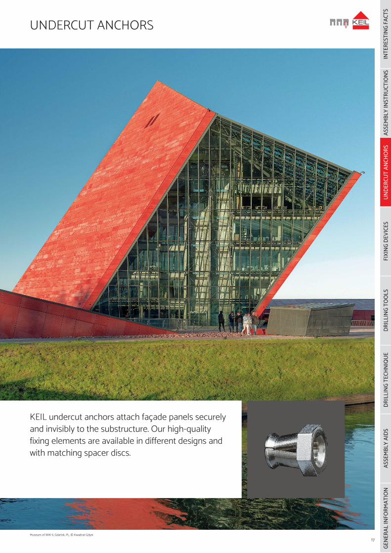
KEIL undercut anchors attach façade panels securely and invisibly to the substructure. Our high-quality fixing elements are available in different designs and with matching spacer discs.
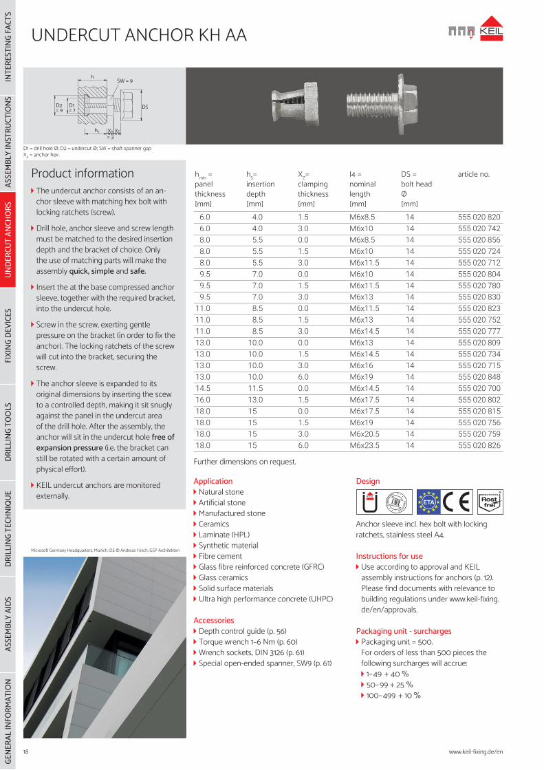
Product information The undercut anchor consists of an an-chor sleeve with matching hex bolt with locking ratchets (screw).
Drill hole, anchor sleeve and screw length must be matched to the desired insertion depth and the bracket of choice. Only the use of matching parts will make the assembly quick, simple and safe.
Insert the at the base compressed anchor sleeve, together with the required bracket, into the undercut hole.
Screw in the screw, exerting gentle pressure on the bracket (in order to fix the anchor). The locking ratchets of the screw will cut into the bracket, securing the screw.
The anchor sleeve is expanded to its original dimensions by inserting the scew to a controlled depth, making it sit snugly against the panel in the undercut area of the drill hole. After the assembly, the anchor will sit in the undercut hole free of expansion pressure (i.e. the bracket can still be rotated with a certain amount of physical effort).
KEIL undercut anchors are monitored externally.
ETA
Application Natural stone Artificial stone Manufactured stone Ceramics Laminate (HPL) Synthetic material Fibre cement Glass fibre reinforced concrete (GFRC) Glass ceramics Solid surface materials Ultra high performance concrete (UHPC)
Accessories Depth control guide (p. 56) Torque wrench 1–6 Nm (p. 60) Wrench sockets, DIN 3126 (p. 61) Special open-ended spanner, SW9 (p. 61)
Instructions for use Use according to approval and KEIL assembly instructions for anchors (p. 12). Please find documents with relevance to building regulations under www.keil-fixing.de/en/approvals.
Packaging unit - surcharges Packaging unit = 500.For orders of less than 500 pieces the following surcharges will accrue: 1–49 + 40 % 50–99 + 25 % 100–499 + 10 %
Instructions for use Use according to KEIL assembly instruc-tions for anchors (p. 12).
Packaging unit - Surcharges Packaging unit = 100.For orders of less than 100 pieces the following surcharges will accrue: 1–49 + 40 % 50–99 + 25 %
hSW = 12
DSD2= 12
D1= 9
hS XA XZ
= 3
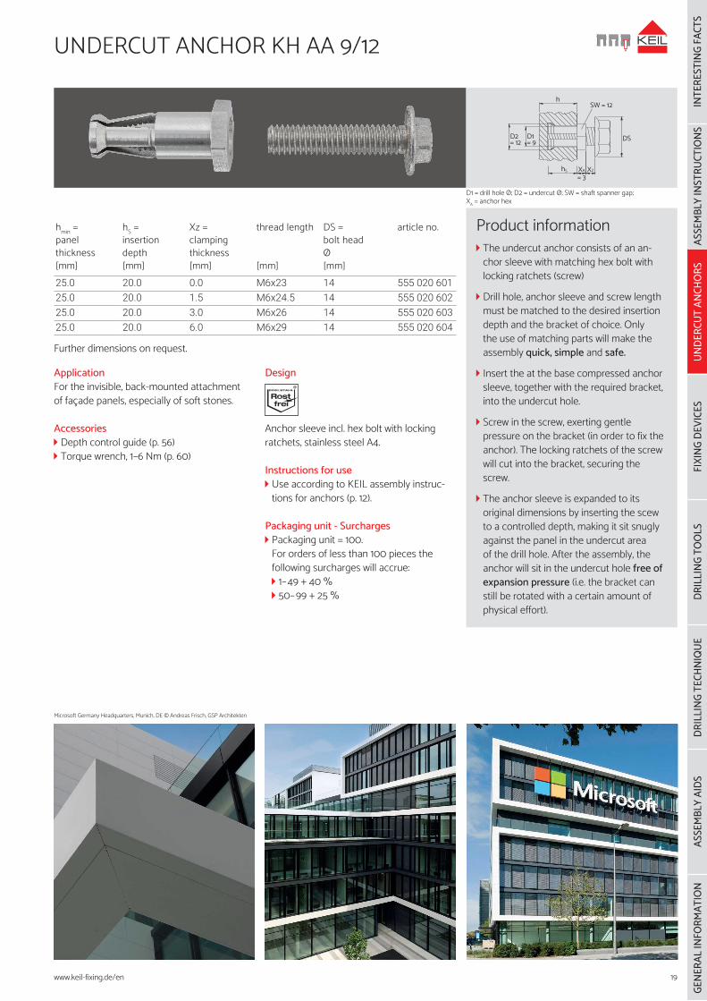
Product information The undercut anchor consists of an an-chor sleeve with matching hex bolt with locking ratchets (screw)
Drill hole, anchor sleeve and screw length must be matched to the desired insertion depth and the bracket of choice. Only the use of matching parts will make the assembly quick, simple and safe.
Insert the at the base compressed anchor sleeve, together with the required bracket, into the undercut hole.
Screw in the screw, exerting gentle pressure on the bracket (in order to fix the anchor). The locking ratchets of the screw will cut into the bracket, securing the screw.
The anchor sleeve is expanded to its original dimensions by inserting the scew to a controlled depth, making it sit snugly against the panel in the undercut area of the drill hole. After the assembly, the anchor will sit in the undercut hole free of expansion pressure (i.e. the bracket can still be rotated with a certain amount of physical effort).
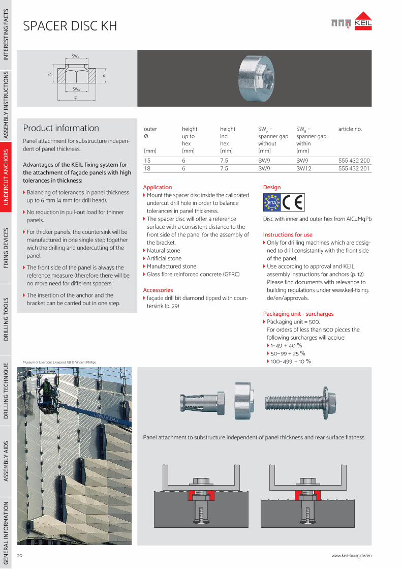
Application Mount the spacer disc inside the calibrated undercut drill hole in order to balance tolerances in panel thickness.
The spacer disc will offer a reference surface with a consistent distance to the front side of the panel for the assembly of the bracket.
Natural stone Artificial stone Manufactured stone Glass fibre reinforced concrete (GFRC)
Accessories façade drill bit diamond tipped with coun-tersink (p. 29)
Design
Disc with inner and outer hex from AlCuMgPb
Instructions for use Only for drilling machines which are desig-ned to drill consistantly with the front side of the panel.
Use according to approval and KEIL assembly instructions for anchors (p. 12). Please find documents with relevance to building regulations under www.keil-fixing.de/en/approvals.
Packaging unit - surcharges Packaging unit = 500.For orders of less than 500 pieces the following surcharges will accrue: 1–49 + 40 % 50–99 + 25 % 100–499 + 10 %
ETA
Product informationPanel attachment for substructure indepen-dent of panel thickness.
Advantages of the KEIL fixing system for the attachment of façade panels with high tolerances in thickness:
Balancing of tolerances in panel thickness up to 6 mm (4 mm for drill head).
No reduction in pull-out load for thinner panels.
For thicker panels, the countersink will be manufactured in one single step together wich the drilling and undercutting of the panel.
The front side of the panel is always the reference measure (therefore there will be no more need for different spacers.
The insertion of the anchor and the bracket can be carried out in one step.
SWA
67,5
SWB
Ø
Panel attachment to substructure independent of panel thickness and rear surface flatness.
Application Natural stone Artificial stone Manufactured stone Ceramics Laminate (HPL) Synthetic material Fibre cement Glass fibre reinforced concrete (GFRC) Glass ceramics
Accessories Depth control guide (p. 56) Wrench sockets, DIN 3126 (p. 61) Special open-ended spanner, SW9 (p. 61) Screw-in tool for stud bolts (p. 61)
Design
Anchor sleeve incl. threaded pin with inner hex and nut with locking ratchets from stainless steel A4
Instructions for use When screwed in, the threaded pin must fit flush with the tip of the anchor sleeve.
Use according to approval and KEIL assembly instructions for anchors (p. 12). Please find documents with relevance to building regulations under www.keil-fixing.de/en/approvals.
Packaging unit - surcharges Packaging unit = 500.For orders of less than 500 pieces the following surcharges will accrue: 1–49 + 40 % 50–99 + 25 % 100–499 + 10 %
Product information The undercut anchor consists of an an-chor sleeve, a threaded pin and a nut with locking ratchets.
Drill hole, anchor sleeve and threaded pin length must be matched to the desired insertion depth and the bracket of choice. Only the use of matching parts will make the assembly quick, simple and safe.
Insert the at the base compressed anchor sleeve into the undercut hole.
The anchor sleeve is expanded to its origi-nal dimensions by inserting the threaded pin to a controlled depth, making it sit snugly against the panel in the undercut area of the drill hole. After the assembly, the anchor will sit in the undercut hole free of expansion pressure (i.e. the bracket can still be rotated with a certain amount of physical effort).
Applications Natural stone Artificial stone Manufactured stone Ceramics Laminate (HPL) Synthetic material Fibre cement Glass ceramics
Accessories Depth control guide (p. 56) Special open-ended wrench, SW9 (p. 61)
Design
Anchor sleeve incl. reduced threaded bolt from stainless steel A4
Instructions for use from l4 > 90 mm surface grooving onwards Use according to approval and KEIL assembly instructions for anchors (p. 12). Please find documents with relevance to building regulations under www.keil-fixing.de/en/approvals.
Packaging - surcharges Packaging unit = 500.For orders of less than 500 pieces the
following surcharges will accrue: 1–49 + 40 % 50–99 + 25 % 100–499 + 10 %
Product information The KEIL plug-in-bolt in connection with the KEIL undercut anchor allows for the attachment of natural stone panels without any substructure.
The retaining and load-baring bolts are attached to the back side of the panel with the aid of the undercut anchor.
The holes drilled into the substrate are filled with permissible mortar.
The plug-in-bolts on the façade panel are inserted into the filled drill holes.
The façade panel is adjusted and fixed. After the temperature-related setting time, the panel is anchored safely and without expansion pressure. With/without insula-tion.
Single panels can be replaced subsequent-ly.
High degree in safety due to the optimal distribution of the weight load.
The correct screw-in depth is warranted by the system.