36
D GB F USA NL Modell der Dampflokomotive Mikado, B&O 22816
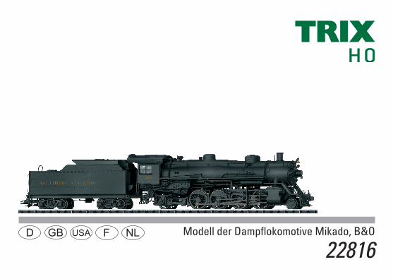
D GB F USA NL Modell der Dampflokomotive Mikado, B&O
22816

2

3
Inhaltsverzeichnis: SeiteInformationen zum Vorbild 4Betriebshinweise 6Sicherheitshinweise 8Wichtige Hinweise 8Multiprotokollbetrieb 8Schaltbare Funktionen 11Parameter/Register 12Wartung und Instandhaltung 28Ersatzteile 33
Table of Contents: Page Information about the prototype 4Information about operation 6Safety Notes 13Important Notes 13Multi-Protocol Operation 13Controllable Functions 16Parameter/Register 17Service and maintenance 28Spare Parts 33
Sommaire : PageInformations concernant la locomotive réelle 5Remarques sur l’exploitation 6Remarques importantes sur la sécurité 18Information importante 18Mode multiprotocole 18Fonctions commutables 21Paramètre/Registre 22Entretien et maintien 28Pièces de rechange 33
Inhoudsopgave: PaginaInformatie van het voorbeeld 5Opmerkingen over de werking 6Veiligheidsvoorschriften 23Belangrijke aanwijzing 23Multiprotocolbedrijf 23Schakelbare functies 26Parameter/Register 27Onderhoud en handhaving 28Onderdelen 33

4
Informationen zum VorbildBedingt durch die besonderen Anforderungen an das Eisen-bahnwesen im 1. Weltkrieg wurde von den USA im Jahre 1917 die United States Railroad Administration (USRA) als übergeord-nete Behörde für die vielen privaten amerikanischen Eisenbahn-linien gegründet. Diese Vereinigung definierte als eine der vielen Aufgaben auch die Merkmale diverser Standard-Lokbaureihen, zu denen auch die Mehr zwecklokomotive „Mikado“ mit der Achsfolge 1-D-1 (Radfolge 2-8-2) gehörte. Der Name „Mikado“ stammt von einer japanischen Dampflokomotiv-Baureihe ab, die 1897 zum ersten Mal mit dieser Achsfolge realisiert wurde. Heute steht der Name „Mikado“ als Synonym für Dampflokomo-tiven mit dieser Achsfolge. Das Konzept dieser Standard-Lokomotiven der USRA wurden auch nach dem Ende des 1. Welt krieges und der anschließenden Auflösung der USRA von den meisten privaten Eisenbahngesell-schaften weiter gepflegt. Dadurch gehörten die Mikado-Lokomotiven zum typischen Erscheinungsbild der Eisenbahn in den USA in der ersten Hälfte des 20. Jahrhunderts. Erst der Siegeszug des Dieselmotors sorgte für ein Ende dieser bis heute unter Eisenbahnern sehr geschätzten Dampflok-Bauart.
Information about the PrototypeThe United States Railroad Administration (USRA) was establis-hed in 1917 by the American government as a governing autho-rity for the many private American railroads in response to the special demands made on the railroads in World War I. As one of its many tasks, this authority defined the features of different standard locomotive classes, among them the general-purpose “Mikado” with its 2-8-2 wheel arrangement. The name “Mikado” comes from a Japanese steam locomotive class that was built for the first time in 1897 with this wheel arrange ment. Today the name “Mikado” is a synonym for steam locomotives with this wheel arrangement. The concept of these USRA standard locomotives was continu-ed and refined by many of the privately owned railroads after the end of World War I and the accompanying dismantling of the USRA. The Mikado locomotives thereby became a part of the daily railroad scene in the USA in the first half of the 20th century. Only the arrival of the diesel motor in railroading circles signaled the end of this steam locomotive design that is so beloved among rail roaders.
5
Informations concernant la locomotive réelle Eu égard aux problèmes rencontrés dans le domaine du transport ferroviaire au cours de la Première Guerre mondiale, le gouvernement fédéral des Etats- Unis fonda en 1917 la “United States Railroad Administration” (USRA) qui désormais allait chapeauter les nombreuses administrations ferroviaires améri-cai nes privées. Parmi les nombreuses missions dont elle était chargée, cette association avait la tâche de définir les caracté-ristiques de diverses séries de loco motives standards, dont fai-sait partie la polyvalente „Mikado“ à disposition d’essieux 1-D-1 (2-8-2). Le nom de „Mikado“ provient d’une série de loco motives à vapeur japonaises qui en 1897 avaient été construites pour la première fois avec cette disposi tion d’essieux. Par la suite et jusqu’à aujourd’hui, cette appellation „Mikado“ est restée en usage pour désigner les locomotives à vapeur présentant cette disposition d’essieux. Après la fin des hostilités et la dissolution de l’USRA, le concept de ces locomotives standards de l’USRA est resté d’application dans la plupart des compagnies ferroviaires américaines. Les locomotives Mika do ont ainsi fait partie du paysage ferroviaire quotidien aux Etats-Unis durant la première moitié du vingtième siècle. Le chant victorieux des machines diesels a ensuite irréversiblement sonné le glas de la locomotive à vapeur que, de nos jours, maints amateurs ferroviaires continuent d’apprécier et admirer.
Informatie van het voorbeeld Wegens de bijzondere eisen die de Eerste Wereld oorlog aan het spoorwegwezen stelde, werd door de USA in 1917 de United States Railroad Administration (USRA) als overkoepelende verantwoordelijke voor de vele particuliere Amerikaanse spoor-wegmaatschappijen opgericht. Deze organisatie defi nieerde als een van de taken ook de kenmerken van diverse standaard- loc-series, waaronder ook de multifunctionele locomotief „Mikado“ met de asindeling 1-D-1 (wielindeling 2-8-2) behoorde. De naam „Mikado“ komt van een Japanse stoom locomotiefserie, die in 1897 voor de eerste keer met deze asindeling gerealiseerd werd. Tegenwoordig is de naam „Mikado“ als synoniem voor stoomlo-comotieven met deze asindeling. Het concept van deze standaardlocomotieven van de USRA werden ook na het einde van de Eerste Wereldoorlog en de aansluitende opheffing van de USRA door de meeste particu-liere spoorwegmaatschappijen verder behouden. Daardoor behoorden de Mikado-locomotieven tot het typische beeld van de spoorwegen in de USA in de eerste helft van de 20ste eeuw. Pas de zegetocht van de dieselmotor zorgde voor het einde van deze tot op heden onder spoorweglieden zeer gewaardeerde stoomloc-type.
6

7
Lokführer und Heizer einsetzenKeinen Sekundenkleber verwenden!
Installing the locomotive engineer and firemanDo not use super glue!
Mettre le conducteur de la locomotive et le chauffeur en placeNe pas utiliser de colle à contact immédiat!
Loc-machinist en stoker plaatsenGeen secondenlijm gebruiken!
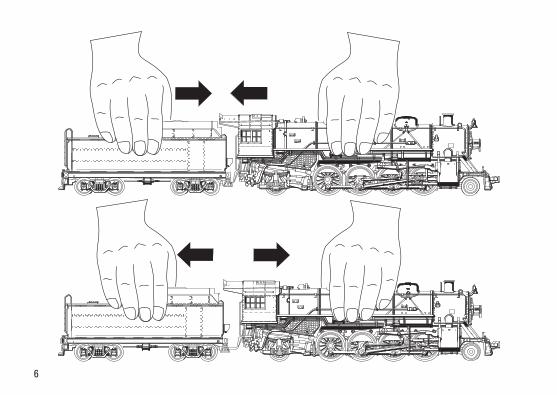
Die Kurzkupplung zwischen Lok und Tender ist verstellbar. Der kurze Abstand ist für den Fahrbetrieb nicht geeignet. Um den Abstand zu verändern, die Lok und den Tender auf dem geraden Gleis stehend vorsichtig zusammenschieben bzw. auseinanderziehen.
The close coupling between the locomotive and tender is adjustable. The short spacing is not suitable for running the locomotive. In order to change the spacing, place the locomotive and tender on straight track and carefully push them together or pull them away from each other.
L’attelage court entre loco et tender est réglable. L’espace court ne convient pas pour l’exploitation. Pour modifier l’écart, poser loco et tender sur un élément de voie droit et les pousser délicatement l’un vers l’autre ou les éloigner, selon le cas.
De kortkoppeling tussen loc en tender is verstelbaar. De korte afstand is niet geschikt voor het rijbedrijf. Om de afstand te veranderen, de loc en tender op een recht railstuk plaatsen en voorzichtig naar elkaar schuiven resp. uit elkaar trekken.

8
Sicherheitshinweise • DieLokdarfnurmiteinemdafürbestimmtenBetriebssystem
eingesetzt werden.• Analogmax.15Volt=,digitalmax.22Volt~.• DieLokdarfnurauseinerLeistungsquelleversorgtwerden.• BeachtenSieunbedingtdieSicherheitshinweiseinder
Bedienungsanleitung zu Ihrem Betriebssystem.• FürdenkonventionellenBetriebderLokmussdasAnschluss-
gleis entstört werden. Dazu ist das Entstörset 611 655 zu ver-wenden. Für Digitalbetrieb ist das Entstörset nicht geeignet.
• ACHTUNG! Funktionsbedingte scharfe Kanten und Spitzen.• SetzenSiedasModellkeinerdirektenSonneneinstrahlung,
starken Temperaturschwankungen oder hoher Luftfeuchtig-keit aus.
• VerbauteLED`sentsprechenderLaserklasse1nachNorm EN 60825-1.
Wichtige Hinweise • DieBedienungsanleitungunddieVerpackungsindBestand-
teile des Produktes und müssen deshalb aufbewahrt sowie bei Weitergabe des Produktes mitgegeben werden.
• FürReparaturenoderErsatzteilewendenSiesichbitteanIhren Trix-Fachhändler.
• GewährleistungundGarantiegemäßderbeiliegenden Garantieurkunde.
• Entsorgung:www.maerklin.com/en/imprint.html• DervolleFunktionsumfangistnurunterTrixSystems,DCC
und unter mfx verfügbar.• Eingebaute,fahrtrichtungsabhängigeStirnbeleuchtung.
Im Digitalbetrieb schaltbar.
• BefahrbarerMindestradius360mm.
Multiprotokollbetrieb AnalogbetriebDer Decoder kann auch auf analogen Anlagen oder Gleisab-schnitten betrieben werden. Der Decoder erkennt die analoge Gleichspannung (DC) automatisch und passt sich der analogen Gleisspannung an. Es sind alle Funktionen, die unter mfx oder DCC für den Analogbetrieb eingestellt wurden aktiv (siehe Digitalbetrieb).DigitalbetriebDer Decoder ist ein Multiprotokolldecoder. Der Decoder kann unter folgendenDigital-Protokolleneingesetztwerden:mfxoderDCC.Das Digital-Protokoll mit den meisten Möglichkeiten ist das höchstwertige Digital-Protokoll. Die Reihenfolge der Digital-ProtokolleistinderWertungfallend: Priorität1:mfx Priorität2:DCC Priorität3:DCHinweis: Werden zwei oder mehrere Digital-Protokolle am Gleis erkannt, übernimmt der Decoder automatisch das höchstwertige Digital-Protokoll, z.B. mfx/DCC, somit wird das mfx-Digital-Proto-koll vom Decoder übernommen. Hinweis: Beachten Sie, dass nicht alle Funktionen in allen Digital-Protokollen möglich sind. Unter mfx und DCC können einige Einstellungen von Funktionen, welche im Analog-Betrieb wirksam sein sollen, vorgenommen werden.

9
Hinweise zum Digitalbetrieb • DiegenaueVorgehensweisezumEinstellenderdiversen
Parameter entnehmen Sie bitte der Bedienungsanleitung Ihrer Mehrzug-Zentrale.
• DerBetriebmitgegenpoligerGleichspannungimBremsab-schnitt ist mit der werkseitigen Einstellung nicht möglich. Ist diese Eigenschaft gewünscht, so muss auf den konventio-nellenGleichstrombetriebverzichtetwerden(CV29/Bit2=0).
mfx-ProtokollAdressierung • KeineAdresseerforderlich,jederDecodererhälteineeinma-
lige und eindeutige Kennung (UID).• DerDecodermeldetsichaneinerCentralStationoderMobile
Station mit seiner UID automatisch an.• NameabWerk:Mikado 4526 B&OProgrammierung• DieEigenschaftenkönnenüberdiegrafischeOberflächeder
Central Station bzw. teilweise auch mit der Mobile Station programmiert werden.
• EskönnenalleConfigurationVariablen(CV)mehrfachgele-sen und programmiert werden.
• DieProgrammierungkannentwederaufdemHaupt-oderdem Programmiergleis erfolgen.
• DieDefaulteinstellungen(Werkseinstellungen)könnenwieder hergestellt werden.
• Funktionsmapping:FunktionenkönnenmitHilfederCentralStation 60212 (eingeschränkt) und mit der Central Station 60213/60214/60215 beliebigen Funktionstasten zugeordnet werden (Siehe Hilfe in der Central Station).
DCC-ProtokollAdressierung• KurzeAdresse–LangeAdresse–Traktionsadresse• Adressbereich:
1 - 127 kurze Adresse, Traktionsadresse 1 - 10239 lange Adresse• JedeAdresseistmanuellprogrammierbar.• KurzeoderlangeAdressewirdüberdieCVsausgewählt.• EineangewandteTraktionsadressedeaktiviertdieStandard-
Adresse.

10
Programmierung• DieEigenschaftenkönnenüberdieConfigurationsVariablen
(CV) mehrfach geändert werden. • DieCV-NummerunddieCV-Wertewerdendirekteingegeben.• DieCVskönnenmehrfachgelesenundprogrammiertwerden
(Programmierung auf dem Programmiergleis).• DieCVskönnenbeliebigprogrammiertwerden(Programmie-
rung auf dem Hauptgleis PoM). PoM ist nur bei den in der CV-Tabelle gekennzeichneten CV möglich. Die Programmierung auf dem Hauptgleis (PoM) muss von Ihrer Zentrale unterstützt werden (siehe Bedienungsanleitung ihres Gerätes).
• DieDefaulteinstellungen(Werkseinstellungen)könnenwieder hergestellt werden.
• 14bzw.28/126Fahrstufeneinstellbar.• AlleFunktionenkönnenentsprechenddemFunktionsmapping
geschaltet werden.• WeitereInformation,sieheCV-TabelleDCC-Protokoll.Es wird empfohlen, die Programmierungen grundsätzlich auf dem Programmiergleis vorzunehmen.
Logische FunktionenAnfahr-/Bremsverzögerung• DieBeschleunigungs-undBremszeitkanngetrenntvonei-
nander eingestellt werden. • DielogischeFunktionsabschaltungABVkannüberdas
Funktionsmapping auf jede beliebige Funktionstaste gelegt werden.

11
Schaltbare Funktionen
Stirnbeleuchtung an Funktion f0 Funktion f0
Rauchgenerator 1 an Funktion 1 Funktion f1 Funktion f1
Betriebsgeräusch — Funktion 2 Funktion f2 Funktion f2
Geräusch:Lokpfeife — Funktion 3 Funktion f3 Funktion f3
ABV, aus — Funktion 4 Funktion f4 Funktion f4
Geräusch:Bremsenquietschenaus — Funktion 5 Funktion f5 Funktion f5
Geräusch:PfeifsequenzvorBahnübergang — Funktion 6 Funktion f6 Funktion f6
Geräusch:Glocke — Funktion 7 Funktion f7 Funktion f7
Geräusch:Luftpumpe — Funktion 8 Funktion f8 Funktion f8
Geräusch:Injektor — — Funktion f9 Funktion f9
Geräusch:Hilfsbläser — — Funktion f10 Funktion f10
Geräusch:Ankuppeln/Abkuppeln — — Funktion f11 Funktion f11
Geräusch:Schienenstöße — — Funktion f12 Funktion f12
Geräusch:Abschlammen — — Funktion f13 Funktion f13
1 Gehört nicht zum Lieferumfang
f0 - f3 f4 - f7

12
CV Bedeutung Wert DCC ab Werk
1 Adresse 1 - 127 3
2 PoM Minimalgeschwindigkeit 0 - 255 5
3 PoM Anfahrverzögerung 0 - 255 15
4 PoM Bremsverzögerung 0 - 255 17
5 PoM Maximalgeschwindigkeit 0 - 255 255
8 Werkreset/Herstellerkennung 8 131
13 PoM Funktionen F1 - F8 im Analogbetrieb 0 - 255 0
14 PoM Funktionen F9 - F15 und Licht im Analogbetrieb 0 - 255 1
17 Erweiterte Adresse (oberer Teil) CV29,Bit5=1 192
18 Erweiterte Adresse (unterer Teil) CV29,Bit5=1 128
19 Traktionsadresse 0 - 255 0
21 PoM Funktionen F1 - F8 bei Traktion 0 - 255 0
22 PoM Funktionen F9 - F15 und Licht bei Traktion 0 - 255 0
29
Bit0:UmpolungFahrtrichtung Bit1:AnzahlFahrstufen14oder28/128* Bit2:DCCBetriebmitBremsstrecke (kein Analogbetrieb möglich) Bit5:Adressumfang7Bit/14Bit
0 / 1 0 / 2 0 / 4
0 / 32
0, 1, 2, 3, 4, 5, 6, 7, 32, 34, 35, 36, 37,
38, 396
63 Lautstärke 0 - 255 255
* FahrstufenamLokdecoderundamSteuergerätmüssenübereinstimmen,essindsonstFehlfunktionenmöglich.
13
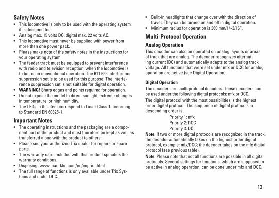
• Built-inheadlightsthatchangeoverwiththedirectionoftravel. They can be turned on and off in digital operation.
• Minimumradiusforoperationis360mm/14-3/16“.
Multi-Protocol Operation Analog OperationThis decoder can also be operated on analog layouts or areas of track that are analog. The decoder recognizes alternat-ing current (DC) and automatically adapts to the analog track voltage. All functions that were set under mfx or DCC for analog operation are active (see Digital Operation).
Digital OperationThe decoders are multi-protocol decoders. These decoders can beusedunderthefollowingdigitalprotocols:mfxorDCC.The digital protocol with the most possibilities is the highest order digital protocol. The sequence of digital protocols in descendingorderis: Priority1:mfx Priority2:DCC Priority3:DCNote: If two or more digital protocols are recognized in the track, the decoder automatically takes on the highest order digital protocol,example:mfx/DCC;thedecodertakesonthemfxdigitalprotocol (see previous table).Note: Please note that not all functions are possible in all digital protocols. Several settings for functions, which are supposed to be active in analog operation, can be done under mfx and DCC.
Safety Notes• Thislocomotiveisonlytobeusedwiththeoperatingsystem
it is designed for.• Analogmax.15voltsDC,digitalmax.22voltsAC.• Thislocomotivemustneverbesuppliedwithpowerfrom
more than one power pack.• Pleasemakenoteofthesafetynotesintheinstructionsfor
your operating system.• Thefeedertrackmustbeequippedtopreventinterference
with radio and television reception, when the locomotive is to be run in conventional operation. The 611 655 interference suppression set is to be used for this purpose. The interfe-rence suppression set is not suitable for digital operation.
• WARNING! Sharp edges and points required for operation.• Donotexposethemodeltodirectsunlight,extremechanges
in temperature, or high humidity. • TheLEDsinthisitemcorrespondtoLaserClass1according
to Standard EN 60825-1.
Important Notes• Theoperatinginstructionsandthepackagingareacompo-
nent part of the product and must therefore be kept as well as transferred along with the product to others.
• PleaseseeyourauthorizedTrixdealerforrepairsorspareparts.
• Thewarrantycardincludedwiththisproductspecifiesthewarranty conditions.
• Disposing:www.maerklin.com/en/imprint.html• ThefullrangeoffunctionsisonlyavailableunderTrixSys-
tems and under DCC.

14
Notes on digital operation • Theoperatinginstructionsforyourcentralunitwillgiveyou
exact procedures for setting the different parameters. • Thesettingdoneatthefactorydoesnotpermitoperationwith
opposite polarity DC power in the braking block. If you want this characteristic, you must do without conventional DC poweroperation(CV29/Bit2=0).
mfx Protocol
Addresses • Noaddressisrequired;eachdecoderisgivenaone-time,
unique identifier (UID).• ThedecoderautomaticallyregistersitselfonaCentralStation
or a Mobile Station with its UID.• Namesetatthefactory:Mikado 4526 B&O
Programming • Thecharacteristicscanbeprogrammedusingthegraphic
screen on the Central Station or also partially with the Mobile Station.
• AlloftheConfigurationVariables(CV)canbereadandprogrammed repeatedly.
• Theprogrammingcanbedoneeitheronthemaintrackortheprogramming track.
• Thedefaultsettings(factorysettings)canbeproducedrepeatedly.
• Functionmapping:Functionscanbeassignedtoanyofthefunction buttons with the help of the 60212 Central Station (with limitations) and with the 60213/60214/60215 Central Sta-tion (See help section in the Central Station).
DCC Protocol
Addresses • Shortaddress–longaddress–multipleunitaddress• Addressrange:
1 - 127 for short address and multiple unit address, 1 - 10239 for long address
• Everyaddresscanbeprogrammedmanually.• AshortoralongaddressisselectedusingtheCVs.• Amultipleunitaddressthatisbeinguseddeactivatesthe
standard address.

15
Programming• Thecharacteristicscanbechangedrepeatedlyusingthe
Configuration Variables (CV).• TheCVnumbersandtheCVvaluesareentereddirectly.• TheCVscanbereadandprogrammedrepeatedly.(Program-
ming is done on the programming track.)• TheCVscanbeprogrammedinanyorderdesired.(Program-
ming can be done on the main track PoM). The PoM can only be done with those designated in the CV table. Programming on the main track PoM must be supported by your central controller (Please see the description for this unit.).
• Thedefaultsettings(factorysettings)canbeproducedrepeatedly.
• 14/28or126speedlevelscanbeset.• Allofthefunctionscanbecontrolledaccordingtothefunc-
tion mapping (see CV description). • SeetheCVdescriptionfortheDCCprotocolforadditional
information.We recommend that in general programming should be done on the programming track.
Logic Functions
Acceleration/Braking Delay • Theaccelerationandbrakingtimecanbesetseparatelyfrom
each other.• ThelogicfunctionABVcanbeassignedtoanyfunction
button by using the function mapping.

16
Controllable Functions
Headlights on Function f0 Function f0
Smoke generator 1 on Function 1 Function f1 Function f1
Operating sounds — Function 2 Function f2 Function f2
Soundeffect:Locomotivewhistle — Function 3 Function f3 Function f3
ABV, off — Function 4 Function f4 Function f4
Soundeffect:Squealingbrakesoff — Function 5 Function f5 Function f5
Soundeffect:Whistlesequencebeforeagradecrossing — Function 6 Function f6 Function f6
Soundeffect:Bell — Function 7 Function f7 Function f7
Soundeffect:Airpump — Function 8 Function f8 Function f8
Soundeffect:Injector — — Function f9 Function f9
Soundeffect:AuxiliaryBlower — — Function f10 Function f10
Soundeffect:Coupling/uncoupling — — Function f11 Function f11
Soundeffect:Railjoints — — Function f12 Function f12
Soundeffect:Clearingsludge — — Function f13 Function f13
1 Not included in delivery scope.
f0 - f3 f4 - f7

17
CV Discription DCC Value Factory-Set
1 Address 1 - 127 3
2 PoM Minimum Speed 0 - 255 5
3 PoM Acceleration delay 0 - 255 15
4 PoM Braking delay 0 - 255 17
5 PoM Maximum speed 0 - 255 255
8 Factory Reset / Manufacturer Recognition 8 131
13 PoM Functions F1 - F8 in analog operation 0 - 255 0
14 PoM Functions F9 - F15 and lights in analog operation 0 - 255 1
17 Extended address (upper part) CV29,Bit5=1 192
18 Extended address (lower part) CV29,Bit5=1 128
19 Multiple Unit Address 0 - 255 0
21 PoM Functions F1 - F8 on Multiple Unit 0 - 255 0
22 PoM Functions F9 - F15 and lights on Multiple Unit 0 - 255 0
29
Bit0:Reversingdirection Bit1:Numberofspeedlevels14or28/128* Bit2:DCCoperationwithbrakingarea (no analog operation possible) Bit5:Addresslength7Bit/14Bit
0 / 1 0 / 2 0 / 4
0 / 32
0, 1, 2, 3, 4, 5, 6, 7, 32, 34, 35, 36, 37,
38, 39
6
63 Volume 0 - 255 255
*Thespeedlevelsonthelocomotivedecoderandonthecontrollermustagreewitheachother;otherwise,youmayhavemalfunctions.
18
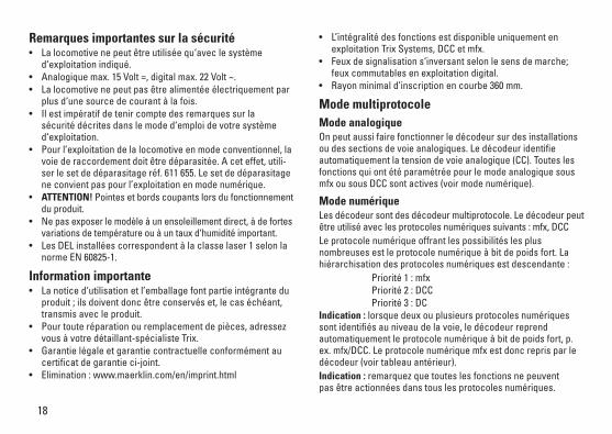
Remarques importantes sur la sécurité • Lalocomotivenepeutêtreutiliséequ‘aveclesystèmed‘exploitationindiqué.
• Analogiquemax.15Volt=,digitalmax.22Volt~.• Lalocomotivenepeutpasêtrealimentéeélectriquementparplusd‘unesourcedecourantàlafois.
• Ilestimpératifdetenircomptedesremarquessurlasécuritédécritesdanslemoded‘emploidevotresystèmed‘exploitation.
• Pour l’exploitation de la locomotive en mode conventionnel, la voiederaccordementdoitêtredéparasitée.Aceteffet,utili-ser le set de déparasitage réf. 611 655. Le set de déparasitage ne convient pas pour l’exploitation en mode numérique.
• ATTENTION! Pointes et bords coupants lors du fonctionnement du produit.
• Ne pas exposer le modèle à un ensoleillement direct, à de fortes variationsdetempératureouàuntauxd‘humiditéimportant.
• LesDELinstalléescorrespondentàlaclasselaser1selonlanorme EN 60825-1.
Information importante• Lanoticed‘utilisationetl’emballagefontpartieintégranteduproduit;ilsdoiventdoncêtreconservéset,lecaséchéant,transmis avec le produit.
• Pourtouteréparationouremplacementdepièces,adressezvous à votre détaillant-spécialiste Trix.
• Garantielégaleetgarantiecontractuelleconformémentaucertificat de garantie ci-joint.
• Elimination:www.maerklin.com/en/imprint.html
• L’intégralitédesfonctionsestdisponibleuniquementenexploitation Trix Systems, DCC et mfx.
• Feuxdesignalisations‘inversantselonlesensdemarche;feux commutables en exploitation digital.
• Rayonminimald’inscriptionencourbe360mm.
Mode multiprotocole Mode analogiqueOn peut aussi faire fonctionner le décodeur sur des installations ou des sections de voie analogiques. Le décodeur identifie automatiquement la tension de voie analogique (CC). Toutes les fonctions qui ont été paramétrée pour le mode analogique sous mfx ou sous DCC sont actives (voir mode numérique).
Mode numériqueLes décodeur sont des décodeur multiprotocole. Le décodeur peut êtreutiliséaveclesprotocolesnumériquessuivants:mfx,DCCLe protocole numérique offrant les possibilités les plus nombreuses est le protocole numérique à bit de poids fort. La hiérarchisationdesprotocolesnumériquesestdescendante: Priorité1:mfx Priorité2:DCC Priorité3:DCIndication : lorsque deux ou plusieurs protocoles numériques sont identifiés au niveau de la voie, le décodeur reprend automatiquement le protocole numérique à bit de poids fort, p. ex. mfx/DCC. Le protocole numérique mfx est donc repris par le décodeur (voir tableau antérieur).Indication : remarquez que toutes les fonctions ne peuvent pasêtreactionnéesdanstouslesprotocolesnumériques.
19
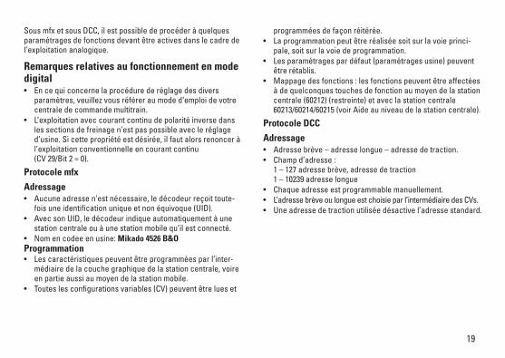
Sous mfx et sous DCC, il est possible de procéder à quelques paramétragesdefonctionsdevantêtreactivesdanslecadredel’exploitation analogique.
Remarques relatives au fonctionnement en mode digital • Encequiconcernelaprocédurederéglagedesdiversparamètres,veuillezvousréféreraumoded‘emploidevotrecentrale de commande multitrain.
• L’exploitationaveccourantcontinudepolaritéinversedansles sections de freinage n’est pas possible avec le réglage d’usine. Si cette propriété est désirée, il faut alors renoncer à l’exploitation conventionnelle en courant continu (CV29/Bit2=0).
Protocole mfx
Adressage • Aucuneadressen’estnécessaire,ledécodeurreçoittoute-
fois une identification unique et non équivoque (UID).• AvecsonUID,ledécodeurindiqueautomatiquementàune
station centrale ou à une station mobile qu’il est connecté.• Nomencodeeenusine:Mikado 4526 B&OProgrammation• Lescaractéristiquespeuventêtreprogramméesparl’inter-
médiaire de la couche graphique de la station centrale, voire en partie aussi au moyen de la station mobile.
• Touteslesconfigurationsvariables(CV)peuventêtrelueset
programméesdefaçonréitérée.• Laprogrammationpeutêtreréaliséesoitsurlavoieprinci-
pale, soit sur la voie de programmation. • Lesparamétragespardéfaut(paramétragesusine)peuventêtrerétablis.
• Mappagedesfonctions:lesfonctionspeuventêtreaffectéesà de quelconques touches de fonction au moyen de la station centrale (60212) (restreinte) et avec la station centrale 60213/60214/60215 (voir Aide au niveau de la station centrale).
Protocole DCC
Adressage• Adressebrève–adresselongue–adressedetraction.• Champd’adresse: 1–127adressebrève,adressedetraction 1–10239adresselongue
• Chaqueadresseestprogrammablemanuellement.• L’adressebrèveoulongueestchoisieparl’intermédiairedesCVs.• Uneadressedetractionutiliséedésactivel’adressestandard.

20
Programmation• Lescaractéristiquespeuventêtremodifiéesdefaçonréitérée
par l’intermédiaire des variables de configuration (CVs). • Touteslesconfigurationsvariables(CV)peuventêtreluesetprogramméesdefaçonréitérée.
• Laprogrammationpeutêtreréaliséesoitsurlavoieprinci-pale, soit sur la voie de programmation.
• LesCVspeuventêtreprogramméeslibrement(programma-tion de la voie principale (PoM). La PoM n’est possible que pour les CVs identifiées dans le tableau des CVs. La program-mationsurlavoieprincipale(PoM)doitêtresupportéeparvotre centrale (voir mode d’emploi de votre appareil).
• Lesparamétragespardéfaut(paramétragesusine)peuventêtrerétablis.
• 14/28,voire126cransdemarchesontparamétrables.• Touteslesfonctionspeuventêtrecommutéesenfonctiondu
mappage des fonctions (voir le descriptif des CVs).• Pourtouteinformationcomplémentaire,voirletableaudes
CVs, protocole DCC. Il est recommandé, de réaliser la programmation, fondamentale-ment, sur la voie de programmation.
Fonctions logiques
Retard au démarrage / au freinage• Lestempsd’accélérationetdefreinagepeuventêtreparamé-
trés séparément les uns des autres. • Parl’intermédiairedumappagedesfonctions,lamisehorsfonctiondelafonctionlogiqueABVpeutêtreaffectéeàn’importe quelle touche de fonction.
21
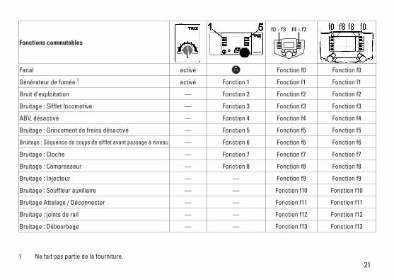
Fonctions commutables
Fanal activé Fonction f0 Fonction f0
Générateur de fumée 1 activé Fonction 1 Fonction f1 Fonction f1
Bruit d’exploitation — Fonction 2 Fonction f2 Fonction f2
Bruitage:Siffletlocomotive — Fonction 3 Fonction f3 Fonction f3
ABV, désactivé — Fonction 4 Fonction f4 Fonction f4
Bruitage:Grincementdefreinsdésactivé — Fonction 5 Fonction f5 Fonction f5
Bruitage:Séquencedecoupsdesiffletavantpassageàniveau — Fonction 6 Fonction f6 Fonction f6
Bruitage:Cloche — Fonction 7 Fonction f7 Fonction f7
Bruitage:Compresseur — Fonction 8 Fonction f8 Fonction f8
Bruitage:Injecteur — — Fonction f9 Fonction f9
Bruitage:Souffleurauxiliaire — — Fonction f10 Fonction f10
Bruitage Attelage / Déconnecter — — Fonction f11 Fonction f11
Bruitage:jointsderail — — Fonction f12 Fonction f12
Bruitage:Débourbage — — Fonction f13 Fonction f13
1 Ne fait pas partie de la fourniture.
f0 - f3 f4 - f7

22
CV Affection DCC Valeur Parm. Usine
1 Adresse 1 - 127 3
2 PoM Vitesse min 0 - 255 5
3 PoM Temporisationd‘accélération 0 - 255 15
4 PoM Temporisation de freinage 0 - 255 17
5 PoM Vitesse maximale 0 - 255 255
8 Réinitialisation d’usine/identification du fabricant 8 131
13 PoM Fonctions F1 - F8 en mode analog 0 - 255 0
14 PoM Fonctions F9 - F15 et éclairage en mode analog 0 - 255 1
17 Adresse étendue (partie supérieure) CV29,Bit5=1 192
18 Adresse étendue (partie inférieure) CV29,Bit5=1 128
19 Adresse traction 0 - 255 0
21 PoM Fonctions F1 - F8 pour traction 0 - 255 0
22 PoM Fonctions F9 - F15 et éclairage traction 0 - 255 0
29
Bit0:Inv.polaritéSensdemarche Bit1:Nombredecransdemarche14ou28/128* Bit2:Mode DCC avec dist. de freinage (mode analog impossible) Bit5:Capacitéd’adresses7Bit/14Bit
0 / 1 0 / 2 0 / 4
0 / 32
0, 1, 2, 3, 4, 5, 6, 7, 32, 34, 35, 36, 37,
38, 396
63 Volume 0 - 255 255
* Pourévitertoutdysfonctionnement,lescransdemarchesurledécodeurdelocodoiventimpérativementcoïncideravecceuxde l’appareil de commande.

23
Veiligheidsvoorschriften• Delocmagalleenmeteendaarvoorbestemdbedrijfssysteem
gebruikt worden.• Analoogmax.15Volt=,digitaalmax.22Volt~.• Delocmagnietvanuitmeerdanéénstroomvoorziening
gelijktijdig gevoed worden.• Leesookaandachtigdeveiligheidsvoorschrifteninde
gebruiksaanwijzing van uw bedrijfssysteem. • Voorhetconventionelebedrijfmetdelocdientdeaansluitrail
te worden ontstoort. Hiervoor dient men de ontstoor-set 611 655 te gebruiken. Voor het digitale bedrijf is deze ontstoor-set niet geschikt.
• OPGEPAST! Functionele scherpe kanten en punten.• Stelhetmodelnietblootaanindirectezonnestraling,sterke
temperatuurwisselingen of hoge luchtvochtigheid. • IngebouwdeLED’skomenovereenmetdelaserklasse1
volgens de norm EN 60825-1.
Belangrijke aanwijzing• Degebruiksaanwijzingendeverpakkingzijneenbestanddeel
van het product en dienen derhalve bewaard en meegeleverd te worden bij het doorgeven van het product.
• VoorreparatiesenonderdelenkuntzichtotUwTrixhandelaarwenden.
• Vrijwaringengarantieovereenkomstighetbijgevoegdegarantiebewijs.
• Afdanken:www.maerklin.com/en/imprint.html• Devolledigetoegangtotallefunctiesisalleenmogelijkmet
Trix Systems, DCC of met mfx bedrijf.
• Ingebouwde,rijrichtingsafhankelijkefrontverlichtingisinhetdigitaalsysteem schakelbaar.
• Minimaleteberijdenradius:360mm.
MultiprotocolbedrijfAnaloogbedrijfDe decoder kan ook op analoge modelbanen of spoortrajecten gebruikt worden. De decoder herkent de analoge gelijkspanning (DC) automatisch en past zich aan de analoge railspanning aan. Alle functies die onder mfx of DCC voor het analoge bedrijf zijn ingesteld, worden geactiveerd (zie digitaalbedrijf).
DigitaalbedrijfDe Decoder is een multiprotocoldecoder. De decoder kan onder devolgendedigitaleprotocolleningezetworden:mfx,DCC.Het digitaalprotocol met de meeste mogelijkheden is het pri-maire digitaalprotocol. De volgorde van de digitaalprotocollen is afnemendinmogelijkheden: Prioriteit1:mfx Prioriteit2:DCC Prioriteit3:DCOpmerking: worden twee of meer digitaal protocollen op de rails herkend, dan neemt de decoder automatisch het protocol met de hoogste prioriteit, bijv. mfx/DCC, dan wordt door de decoder het mfx-digitaalprotocol gebruikt (zie bovenstaand overzicht).Opmerking: let er op dat niet alle functies in alle digitaal-protocollen mogelijk zijn. Onder mfx of DCC kunnen enkele instellingen, welke in analoogbedrijf werkzaam moeten zijn, ingesteld worden.

24
Aanwijzingen voor digitale besturing • Hetopdejuistewijzeinstellenvandediverseparameters
staat beschreven in de handleiding van uw digitale Centrale.• Hetbedrijfmettegengepooldegelijkspanningindeafrem-
sectie is met de fabrieksinstelling niet mogelijk. Indien deze eigenschap wenselijk is, dan moet worden afgezien van het conventioneelgelijkstroombedrijf(CV29/Bit2=0).
Mfx-protocol
Adressering • Eenadresisnietnodig,elkedecoderheefteenéénmaligen
éénduidig kenmerk (UID).• DedecodermeldtzichvanzelfaanbijhetCentralStationof
Mobile Station met zijn UID.• Naamafdefabriek:Mikado 4526 B&O
Programmering • Deeigenschappenkunnenm.b.v.hetgrafischeschermop
het Central Station resp. deels ook met het Mobile Station geprogrammeerd worden.
• Alleconfiguratievariabelen(CV)kunnenvakergelezenengeprogrammeerd worden.
• Deprogrammeringkanzowelophethoofdspooralsophetprogrammeerspoor gebeuren.
• Dedefault-instellingen(fabrieksinstelling)kunnenweerhersteld worden.
• Functiemapping:functieskunnenmetbehulpvanhetCentralStation 60212 (met beperking) en met het Central Station 60213/60214/60215 aan elke gewenste functietoets worden
toegewezen (zie het helpbestand in het Central Station).
DCC-protocol
Adressering • Kortadres–langadres–tractieadres• Adresbereik: 1–127kortadres,tractieadres 1–10239langadres
• Elkadresishandmatigprogrammeerbaar.• KortoflangadreswordtviadeCVgekozen.• Eentoegepasttractieadresdeactiveerthetstandaardadres.
25
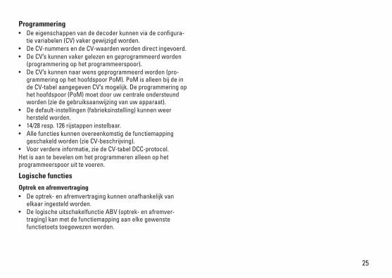
Programmering• Deeigenschappenvandedecoderkunnenviadeconfigura-
tie variabelen (CV) vaker gewijzigd worden.• DeCV-nummersendeCV-waardenwordendirectingevoerd.• DeCV’skunnenvakergelezenengeprogrammeerdworden
(programmering op het programmeerspoor).• DeCV’skunnennaarwensgeprogrammeerdworden(pro-
grammering op het hoofdspoor PoM). PoM is alleen bij de in de CV-tabel aangegeven CV’s mogelijk. De programmering op het hoofdspoor (PoM) moet door uw centrale ondersteund worden (zie de gebruiksaanwijzing van uw apparaat).
• Dedefault-instellingen(fabrieksinstelling)kunnenweerhersteld worden.
• 14/28resp.126rijstappeninstelbaar.• Allefunctieskunnenovereenkomstigdefunctiemapping
geschakeld worden (zie CV-beschrijving).• Voorverdereinformatie,ziedeCV-tabelDCC-protocol.Het is aan te bevelen om het programmeren alleen op het programmeerspoor uit te voeren.
Logische functies
Optrek en afremvertraging• Deoptrek-enafremvertragingkunnenonafhankelijkvan
elkaar ingesteld worden. • DelogischeuitschakelfunctieABV(optrek-enafremver-
traging) kan met de functiemapping aan elke gewenste functietoets toegewezen worden.
26
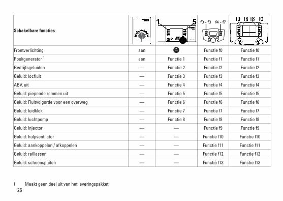
Schakelbare functies
Frontverlichting aan Functie f0 Functie f0
Rookgenerator 1 aan Functie 1 Functie f1 Functie f1
Bedrijfsgeluiden — Functie 2 Functie f2 Functie f2
Geluid:locfluit — Functie 3 Functie f3 Functie f3
ABV, uit — Functie 4 Functie f4 Functie f4
Geluid:piependeremmenuit — Functie 5 Functie f5 Functie f5
Geluid:Fluitvolgordevooreenoverweg — Functie 6 Functie f6 Functie f6
Geluid:luidklok — Functie 7 Functie f7 Functie f7
Geluid:luchtpomp — Functie 8 Functie f8 Functie f8
Geluid:injector — — Functie f9 Functie f9
Geluid:hulpventilator — — Functie f10 Functie f10
Geluid:aankoppelen/afkoppelen — — Functie f11 Functie f11
Geluid:raillassen — — Functie f12 Functie f12
Geluid:schoonspuiten — — Functie f13 Functie f13
1 Maakt geen deel uit van het leveringspakket.
f0 - f3 f4 - f7

27
CV Betekenis Waarde DCC Af fabriek
1 Adres 1 - 127 3
2 PoM minimale snelheid 0 - 255 5
3 PoM Optrekvertraging 0 - 255 15
4 PoM Afremvertraging 0 - 255 17
5 PoM Maximumsnelheid 0 - 255 255
8 Fabrieksinstelling/fabriekherkenning 8 131
13 PoM functies F1 - F8 in analoogbedrijf 0 - 255 0
14 PoM functies F9 - F15 en licht in analoogbedrijf 0 - 255 1
17 Uitgebreld adres (bovenste gedeelte) CV29,Bit5=1 192
18 Uitgebreld adres (onderste gedeelte) CV29,Bit5=1 128
19 tractieadres 0 - 255 0
21 PoM functies F1 - F8 in tractie 0 - 255 0
22 PoM functies F9 - F15 en licht in tractie 0 - 255 0
29
Bit0:ompolenrijrichting Bit1:aantalrijstappen14of28/128*Bit2:DCCbedrijfmetafremtraject(geenanaloogbedrijfmogelijk) Bit5:adresomvang7Bit/14Bit
0 / 1 0 / 2 0 / 4
0 / 32
0, 1, 2, 3, 4, 5, 6, 7, 32, 34, 35, 36, 37,
38, 396
63 Volume 0 - 255 255
* Derijstappeninstellingopdedecoderenhetbesturingsapparaatmoetenmetelkaarovereenkomenanderskunnenerstoringen optreden.
28
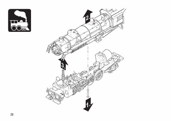
3.
1.
2.

29
Potentielle Fehlerquellen beim Rauchgenerator• DerRauchgeneratordarfnurmaximalhalbmitRauchöl
gefüllt sein.• ImRauchgeneratordarfsichkeineLuftblasebefinden.
Potential Problems with the Smoke Generator• Thesmokegeneratorcannotbefilledanymorethanhalfway
with smoke fluid.• There should not be any air bubbles in the smoke generator.
Causes d‘erreurs potentielles Avec le générateur fumigène• Legénérateurfumigènenepeutpasêtreremplideliquide
fumigène au-delà de la moitié du tube. • Aucunebulled‘airnepeutsetrouverdanslegénérateur
fumigène.
Potentiële storingsoorzaken bij rookgeneratoren• Derookgeneratormagmaximaalhalfmetrookoliegevuld
worden.• Inderookgeneratormagzichgeenluchtbelbevinden.

30
40h

31
1.
2.
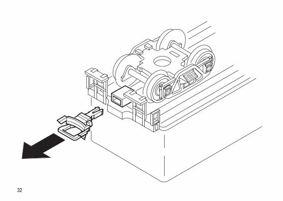
32
33
15
9
25318
66 7
9
4
5
3
4
33
4
4
14
1415
16
23
23
22
16
9
12
4
34
4
1
4
13
18
18
19
19
20
1821
20
18
7
7
7
10
17
11
12
24
Det
ails
der
Dar
stel
lung
kö
nnen
von
dem
Mod
ell
abw
eich
en.
34
27
27
27
28
9
9
29
29
31
33
31
32
36 34
35
30
35
34
26
Det
ails
der
Dar
stel
lung
kö
nnen
von
dem
Mod
ell
abw
eich
en.

35
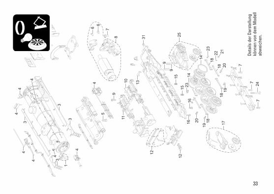
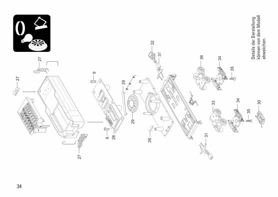
1 Glocke m. Halter E265 014 2 Leiterplatte Stirnbeleuchtung E271 101 3 Umlauf E227 524 4 Ventile, Pumpen, Stangen E265 015 5 Schraube E756 290 6 Schraube E750 040 7 Schraube E786 790 8 Motor m. Getriebe E262 255 9 Schraube E786 750 10 Gestänge links E223 063 11 Gestänge rechts E223 051 12 Steckteile am Vorbau E265 017 13 Haltebügel E222 005 14 Haftreifen 7 153 15 Druckfeder E214 330 16 Schraube E786 330 17 Laufgestell vorne E265 903 18 Kuppelstangen E227 523 19 Sechskantansatzschraube E223 431 20 Sechskantansatzschraube E499 840 21 Sechskantmutter E499 830 22 Scheibe E219 559 23 Sechskantansatzschraube E499 850 24 Schraube E785 200 25 Laufgestell hinten E265 904 26 Haltebügel E209 442 27 Bühne, Deckel, Leiter E265 026 28 Decoder 275 892 29 Lautsprecher E180 731 30 Schleifer E223 241 31 Deichseln, Zugstange E265 038 32 Kurzkupplung E701 630
33 Drehgestell E223 292 34 Drehgestellrahmen E223 078 35 Schraube E750 230 36 Drehgestell E223 293 Lokführer E216 932 Heizer E216 933
Hinweis:EinigeTeilewerdennurohneodermitandererFarbge-bung angeboten. Teile, die hier nicht aufgeführt sind, können nur im Rahmen einer Reparatur im Märklin-Reparatur-Service repariert werden.

277426/0516/Sm1EfÄnderungen vorbehalten
© Gebr. Märklin & Cie. GmbH
Gebr. Märklin & Cie. GmbH Stuttgarter Straße 55 - 5773033 Göppingen Germanywww.trix.de www.maerklin.com/en/imprint.html
Due to different legal requirements regarding electro-magnetic compatibility, this item may be used in the USA only after separate certification for FCC com-pliance and an adjustment if necessary. Use in the USA without this certification is not permitted and absolves us of any liability.Ifyoushouldwantsuchcertificationtobedone,pleasecontactus–also due to the additional costs incurred for this.


