Liste der zu liefernden Dokumente / Dok.–Anforderungs–Beschreibung (LLD/DAB):
Document Requirements List / Doc. Requirements Description (DRL/DRD):
Bearbeitet: Firma:Prepared by: Company:
Geprueft: Firma:Agreed by: Company:
Vertrags–Nr:Contract–No.: _____________________
_________________________________ _________________________________Projekt Manager Projekt Manager
Project Manager Project Manager
Raumfahrt–Infrastruktur
Daimler–Benz Aerospace
ER
NO
Rau
mfa
hrtte
chni
k G
mbH
,290
0 B
rem
en -
All
Rig
hts
Res
erve
d -
Cop
yrig
ht p
er D
IN 3
4E
RN
O 0
19 C
OL/
-
COLUMBUS Ground System (CGS)S/W Architectural Design Document
COL–RIBRE–ADD–006 8–QA
4 09–08–1996
B 30–10–1997
3.716
CGS Engineering Team DASA–RI
P.Athmann, RIO 63 DASA–RI
Dok.-Nr/ Doc. No.:Ausgabe /Issue:
Überarbtg./ Rev.:
Seite/Page:
Datum/ Date:
Datum/ Date:
von/ ofRaumfahrt–Infrastruktur
Daimler–Benz Aerospace
DOCUMENT CHANGE RECORD
ISSUE REV. DATE DESCRIPTION OF CHANGE
ii vii
COL–RIBRE–ADD–0064 09–08–199
6B 30–10–1997
1 – 10–01–1992 First version.
2 – 23–10–1992 Implementation of SSADR DNs.
3 – 31–07–1993 Implementation of CGS Design Changesaccording to DDR including updates forthe following:GSAF: CGS Configs and GSAF FacilitiesGSAF: NSWSW, TSS, no MTFF, no CEGSEROC SDE (no FTT, Data Integration etc)GSAF reorganisation (MPS/VICOSdeletion)General: HP–RT, Mission Generation SW,COLUMBUS SW Stds V4SDE/CSS and SDE/DSA Interfaces
All sections and Objects updated.
4 – 09–08–1996 HOOD update to bring in–line with CGS Build 2/3 Implementation.
4 A 20–12–1996 Description for CPL added,HOOD update to bring in–line with CGS V3.1.3 Implementation.
4 B 30–10–1997 – Change hardware references from sun–4 to sun–5– Include functionalities for CGS 3.2/4.0/4.1: –– SW Commanding –– Binary Packets –– Stable SIDS –– Central Logging
This is the Software Architectural Design for the COLUMBUS CI 1214 597: COLUMBUS GroundSystem (CGS).
CGS is a Software Assembly within the COLUMBUS Ground Software and Avionics Facility (GSAF).
1.1.2 Context
CGS design draws from a number of documents for its information. These are listed below:
* CGS Specification [ref. 2.1.1]
* CGS ICD [ref. 2.1.3.1]
* Standards Documents [ref. 2.1.2]
1.1.3 Constraints
No constraints have been identified.
1.2 Purpose
The purpose of this document is to present the CGS design and to show how the system is broken up andworks together. Traceability to CGS requirements demonstrates the fulfillment of the needs.
1.3 Layout
The CGS ADD follows the general ADD Layout, as described in the COLUMBUS S/W DevelopmentStandards.
However, the following deviations from this standard are noted below:
– Basic concepts, essential for the CGS Architectural Design have been de-scribed in section 3.3.
– Guidelines have been produced in this document to show how the HOODmethod has been applied within the CGS S/W Architectural Design. TheHOOD guidelines have been described within section 3.4.
– In accordance to the overall ADD Layout as described in Issue 4 of theCOLUMBUS S/W Development Standards, it has been found useful tokeep Section 4.3 which describes the CGS external interfaces.
Dok.-Nr/ Doc. No.:Ausgabe /Issue:
Überarbtg./ Rev.:
Seite/Page:
Datum/ Date:
Datum/ Date:
von/ ofRaumfahrt–Infrastruktur
Daimler–Benz Aerospace
2 157
COL–RIBRE–ADD–0064 09–08–1996B 30–10–1997
1.4 Design Approach
The following approach has been taken to establish the CGS Architectural Design:
HOOD Method
* The HOOD Method 3.1 has been used with the following exceptions (see tool limita-tions in section 3.4.3.3):
– No classes and instantiations have been used,
– No operation sets as members of operation sets have been used.
HOOD Tool
* The AdaNice Tool, version 2.1.4 has been used to establish the CGS design. Additionalinterface S/W has been developed in order to:
– Fully automate the generation of HOOD sections 4.2 (CGS Context) and 5(CGS Root Design). This has been done by configuring AdaNice (using theDocument Skeleton Definition Language DSDL), and by developing UNIXScripts and new TPS_STYLES (containing CGS ADD Header, Footer, Frameand Component definitions).
– Provide pretty printed HOOD ODS’s (bold keywords, blank lines). This hasbeen done by developing UNIX awk procedures.
Design Trades
* Design Alternatives/Trade–Offs have been implemented into this document.
Dok.-Nr/ Doc. No.:Ausgabe /Issue:
Überarbtg./ Rev.:
Seite/Page:
Datum/ Date:
Datum/ Date:
von/ ofRaumfahrt–Infrastruktur
Daimler–Benz Aerospace
3 157
COL–RIBRE–ADD–0064 09–08–1996B 30–10–1997
2 APPLICABLE AND REFERENCE DOCUMENTS
2.1 Applicable Documents
The following applicable and reference documents form a part of this document to the extent specifiedherein. In the event of a conflict between the documents referenced and the contents of this document,the contents of this document shall supercede.
2.2.2.2 WME/89–353/JB 3.0 December 89HOOD User Manual
2.2.3 Standards
None
Dok.-Nr/ Doc. No.:Ausgabe /Issue:
Überarbtg./ Rev.:
Seite/Page:
Datum/ Date:
Datum/ Date:
von/ ofRaumfahrt–Infrastruktur
Daimler–Benz Aerospace
5 157
COL–RIBRE–ADD–0064 09–08–1996B 30–10–1997
3 CGS OVERVIEW
This chapter contains a general description of the concept and the functions of CGS. Detailed descrip-tions of the CGS Design Concepts are given in section 3.3.
3.1 CGS Textual Description
This section deals with the with the textual description of CGS. A logical overview of CGS within itsCOLUMBUS environment is given to ease access to the HOOD architectural Chapters of this document.
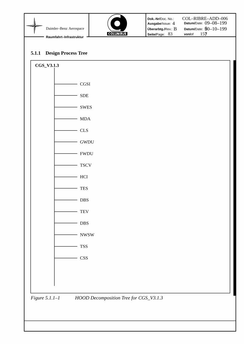
3.1.1 Scope of CGS
3.1.1.1 CGS Objective
The objective of CGS is to provide support for Design and Development and for the Integration, Testand Qualification related activities for the Ground Software Avionics Facility (GSAF) and the internaland external Facilities, within the COLUMBUS Attached Pressurised Module (APM) Space SegmentProgramme. Although it is used mainly for flight software and hardware, CGS also supports develop-ment of ground software.
It is an objective of CGS to provide lifecycle support throughout Production and Operational Phasesof COLUMBUS.
3.1.1.2 CGS Lifecycle Support
COLUMBUS is made up from a number of components. In general COLUMBUS components are: Sys-tem, Subsystem, Assembly and Product. Within this context the expression ”system” is to be seen as ageneric place holder for ”Flight Configuration (FC)”. Systems are integrated Subsystems; Subsystemsare integrated Assemblies; Assemblies are integrated Products. Products may be pure product objects,such as Ada code, FLAP’s (Flight Automated Procedures) and Hardware Units or they may be integratedproduct objects.
COLUMBUS Components follow production lifecycles. This involves moving a component betweena number of phases. This ‘phased model’, segments all the Components into a series of successive acti-vities. Each phase requires well–defined input information, utilises well defined processes, and resultsin well–defined components for the given phase. Resources are required to complete the processes ineach phase, and each phase is accomplished by applying explicit methods, tools and techniques.
All Lifecycles have the following Phases: Analysis, Design, Development, Integration, Test, Qualifica-tion and Maintenance although the formality of each of these varies between component types. SoftwareComponent lifecycles are defined in the COLUMBUS Software Development Standards. The latter alsoidentifies Product Level Lifecycle variants.
CGS supports the software lifecycle. Each component object requires support as it moves betweenphases of its lifecycle. The CGS supported APM Production lifecycle phases are identified in the CGSRequirements Specification [ref. 2.1.1.1 Table 1]. The lifecycle phase and the component object typedetermine which set of CGS Products (or CGS Product ’Configuration’) is required for this support.
Dok.-Nr/ Doc. No.:Ausgabe /Issue:
Überarbtg./ Rev.:
Seite/Page:
Datum/ Date:
Datum/ Date:
von/ ofRaumfahrt–Infrastruktur
Daimler–Benz Aerospace
6 157
COL–RIBRE–ADD–0064 09–08–1996B 30–10–1997
The Formality of lifecycle phases will change during the lifetime of COLUMBUS. During development,components are generated from scratch thus giving maximum freedom for APM Flight Configurationdesign. During the Operational Phase, Flight Hardware remains fairly stable (only the flight crew canmake Hardware changes) and Software is built (where possible) from existing software ‘end items’created during development. Lifecycle formalities will therefore change, although the phases will re-main.
Relationships exist between Lifecycles. There are Vertical and Horizontal relationships. The formerdeals with the starting of lifecycles from other lifecycles; thus the System Lifecycle can start an Assem-bly Lifecycle, an Assembly Lifecycle can start a Product Lifecycle etc. Note that it is desirable to keepthe number of horizontal relationships to a minimum. Note also that vertical relationships almost alwaysoccur at contractual boundaries.
3.1.2 CGS Environment
3.1.2.1 Next Higher Level Component
The Component above CGS in the system tree is the Ground Software Avionics Facility (GSAF), whichis a Subsystem within the COLUMBUS Space Segment. GSAF is a service provider to the APM Usersby implementing a number of Facilities providing environments for APM component development.
CGS is thus a Software Assembly within the COLUMBUS Space Segment, which provides softwareservices as required for GSAF Facilities and hence as required for the APM component. These servicesare needed for the design, development and integration, test and qualification related activities for theAPM Flight Configuration, within the COLUMBUS Space Segment Programme.
CGS is a generic reference concept, encompassing specific CGS ’Add On’ software and CGS will beextended to establish the GSAF internal/external Facilities. Typical Add–Ons beyond others are theCommand, Measurement and Adapatation Systemm (CMAS) and the Front End Software (FES) withinthe ground based Facilities (e.g. SDDF, EGSE and SITE/SSA). Further, by the supply of hardware andsoftware services from a GSAF common source, APM component contractors will be able to reducetheir overheads, this is because APM contractors at different sites will have common tasks such as thewriting and testing of Ada Flight software and the execution of subsystem tests. These common taskswill be supported by appropriate GSAF Facilities.
The configurations making up GSAF Facilities are predefined and the APM contractors choose the Fa-cility most appropriate to their needs (eg for Flight SW development, Flight HW checkout etc). A GSAFFacility is made up from CGS software configurations, standard hardware and additional hardware/soft-ware Add Ons, e.g. Software Design and Development support services, Ground Test equipment andSAS (Special Application Software). Each Facility will be different although each follow a logicalmodel.
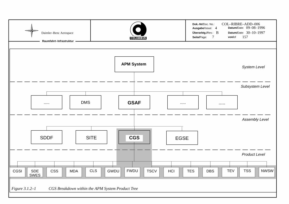
Figure 3.2.1–1 shows the APM Product Tree hierarchy, with the APM at System Level, GSAF at Subsys-tem level, CGS at Assembly Level and the CGS Products which are used to form the different CGS Con-figurations.
Dok.-Nr/ Doc. No.:
Ausgabe /Issue:
Überarbtg./ Rev.:
Seite/Page:
Datum/ Date:
Datum/ Date:
von/ of
Raumfahrt–Infrastruktur
Daimler–Benz Aerospace7 157
COL–RIBRE–ADD–0064 09–08–1996B 30–10–1997
APM SystemSystem Level
Subsystem Level
Assembly Level
Product Level
GSAF ..... .....DMS.....
SDDF EGSESITE CGS
FWDUSDESWES
CSS MDA CLS GWDU TSSTSCV HCI TES DBS TEVCGSI
Figure 3.1.2–1 CGS Breakdown within the APM System Product Tree
NWSW
Dok.-Nr/ Doc. No.:Ausgabe /Issue:
Überarbtg./ Rev.:
Seite/Page:
Datum/ Date:
Datum/ Date:
von/ ofRaumfahrt–Infrastruktur
Daimler–Benz Aerospace
8 157
COL–RIBRE–ADD–0064 09–08–1996B 30–10–1997
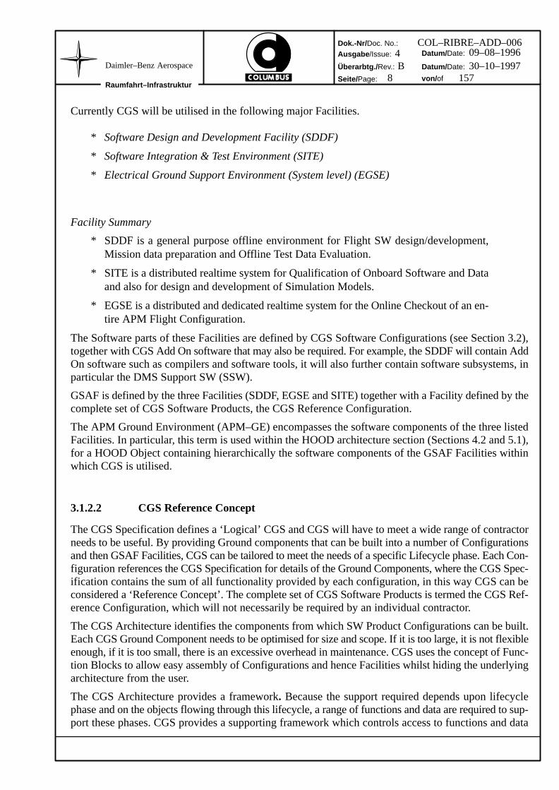
Currently CGS will be utilised in the following major Facilities.
* Software Design and Development Facility (SDDF)
* Software Integration & Test Environment (SITE)
* Electrical Ground Support Environment (System level) (EGSE)
Facility Summary
* SDDF is a general purpose offline environment for Flight SW design/development,Mission data preparation and Offline Test Data Evaluation.
* SITE is a distributed realtime system for Qualification of Onboard Software and Dataand also for design and development of Simulation Models.
* EGSE is a distributed and dedicated realtime system for the Online Checkout of an en-tire APM Flight Configuration.
The Software parts of these Facilities are defined by CGS Software Configurations (see Section 3.2),together with CGS Add On software that may also be required. For example, the SDDF will contain AddOn software such as compilers and software tools, it will also further contain software subsystems, inparticular the DMS Support SW (SSW).
GSAF is defined by the three Facilities (SDDF, EGSE and SITE) together with a Facility defined by thecomplete set of CGS Software Products, the CGS Reference Configuration.
The APM Ground Environment (APM–GE) encompasses the software components of the three listedFacilities. In particular, this term is used within the HOOD architecture section (Sections 4.2 and 5.1),for a HOOD Object containing hierarchically the software components of the GSAF Facilities withinwhich CGS is utilised.
3.1.2.2 CGS Reference Concept
The CGS Specification defines a ‘Logical’ CGS and CGS will have to meet a wide range of contractorneeds to be useful. By providing Ground components that can be built into a number of Configurationsand then GSAF Facilities, CGS can be tailored to meet the needs of a specific Lifecycle phase. Each Con-figuration references the CGS Specification for details of the Ground Components, where the CGS Spec-ification contains the sum of all functionality provided by each configuration, in this way CGS can beconsidered a ‘Reference Concept’. The complete set of CGS Software Products is termed the CGS Ref-erence Configuration, which will not necessarily be required by an individual contractor.
The CGS Architecture identifies the components from which SW Product Configurations can be built.Each CGS Ground Component needs to be optimised for size and scope. If it is too large, it is not flexibleenough, if it is too small, there is an excessive overhead in maintenance. CGS uses the concept of Func-tion Blocks to allow easy assembly of Configurations and hence Facilities whilst hiding the underlyingarchitecture from the user.
The CGS Architecture provides a framework. Because the support required depends upon lifecyclephase and on the objects flowing through this lifecycle, a range of functions and data are required to sup-port these phases. CGS provides a supporting framework which controls access to functions and data
Dok.-Nr/ Doc. No.:Ausgabe /Issue:
Überarbtg./ Rev.:
Seite/Page:
Datum/ Date:
Datum/ Date:
von/ ofRaumfahrt–Infrastruktur
Daimler–Benz Aerospace
9 157
COL–RIBRE–ADD–0064 09–08–1996B 30–10–1997
relevant to each specific task within each lifecycle phase. This framework allows Ground componentsto be added and removed, thus providing a flexible way to build Configurations and Facilities and tomaintain them (e.g. to cover the COLUMBUS Ground Segment).
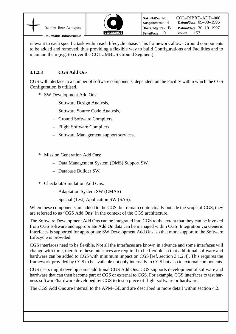
3.1.2.3 CGS Add Ons
CGS will interface to a number of software components, dependent on the Facility within which the CGSConfiguration is utilised.
* SW Development Add Ons:
– Software Design Analysis,
– Software Source Code Analysis,
– Ground Software Compilers,
– Flight Software Compilers,
– Software Management support services,
* Mission Generation Add Ons:
– Data Management System (DMS) Support SW,
– Database Builder SW.
* Checkout/Simulation Add Ons:
– Adaptation System SW (CMAS)
– Special (Test) Application SW (SAS).
When these components are added to the CGS, but remain contractually outside the scope of CGS, theyare referred to as ‘CGS Add Ons’ in the context of the CGS architecture.
The Software Development Add Ons can be integrated into CGS to the extent that they can be invokedfrom CGS software and appropriate Add On data can be managed within CGS. Integration via GenericInterfaces is supported for appropriate SW Development Add Ons, so that more support to the SoftwareLifecycle is provided.
CGS interfaces need to be flexible. Not all the interfaces are known in advance and some interfaces willchange with time, therefore these interfaces are required to be flexible so that additional software andhardware can be added to CGS with minimum impact on CGS [ref. section 3.1.2.4]. This requires theframework provided by CGS to be available not only internally to CGS but also to external components.
CGS users might develop some additional CGS Add Ons. CGS supports development of software andhardware that can then become part of CGS or external to CGS. For example, CGS interfaces to test har-ness software/hardware developed by CGS to test a piece of flight software or hardware.
The CGS Add Ons are internal to the APM–GE and are described in more detail within section 4.2.
Dok.-Nr/ Doc. No.:Ausgabe /Issue:
Überarbtg./ Rev.:
Seite/Page:
Datum/ Date:
Datum/ Date:
von/ ofRaumfahrt–Infrastruktur
Daimler–Benz Aerospace
10 157
COL–RIBRE–ADD–0064 09–08–1996B 30–10–1997
3.1.2.4 Standard Interface Approach
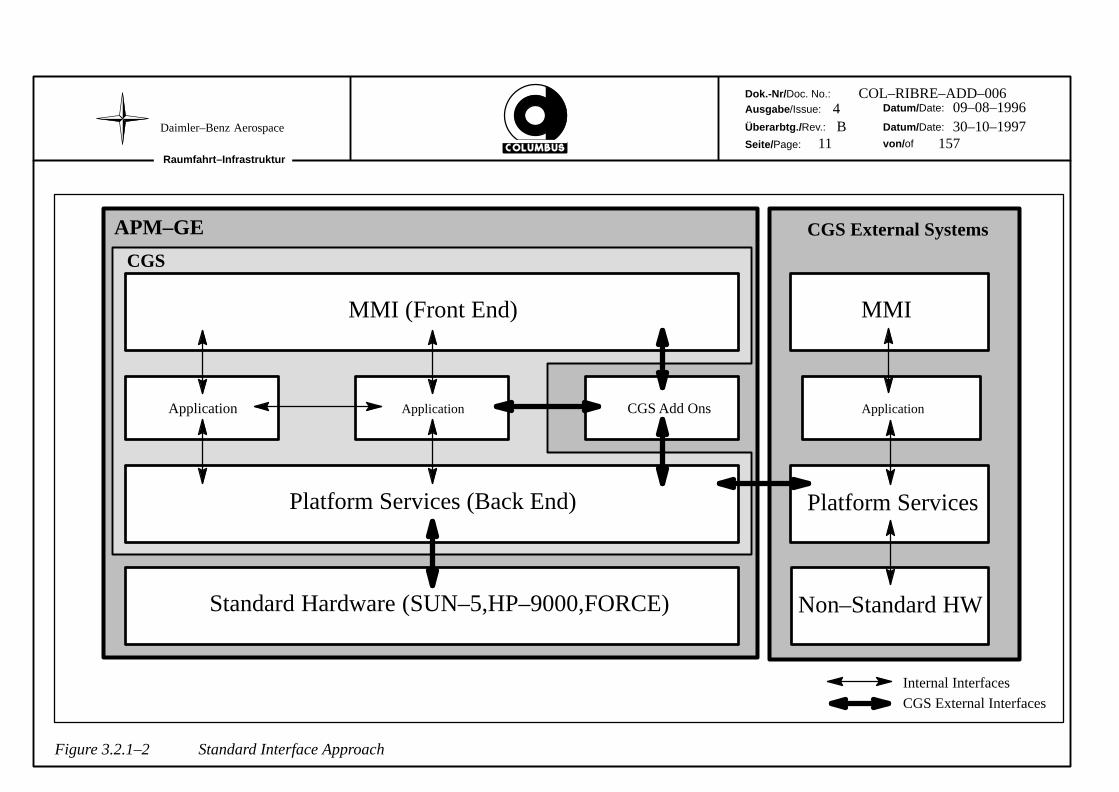
CGS provides three different types of interfaces to the outside world:
* Interface to the User Interface,
* Interface to the CGS Application,
* Interface to the Platform Services.
CGS provides a standard interface mechanism so that additional software can be added and removed toCGS with minimum impact on the CGS operation and architecture. See Figure 3.2.1–2.
Note that the standard interface approach is based on a logical model and therefore might be adoptedto the real needs of the interfacing SW application.
The MMI and platform services can in some cases be provided to the CGS Add On via the Application.For example, the invocation of a CGS Add On might be performed directly from the CGS Top LevelUser Interface or by another CGS Application (e.g. Onboard Support SW).
Standard Interfaces are available to any outside application that requires them.
For Software Development Add On software, there is an Application Interface providing a greater levelof cohesion. It enables the invocation of Add On Tools via a Generic Tool Interface and the use of AddOn Compiler environments via a Generic Compiler Interface. Invocations are supported from withinCGS and data associated with the Add On Software can be managed by CGS Configuration Managementfacilities. The User is able to tailor these interfaces for appropriate options and parameters.
Note that the CGS application interfaces to the underlying hardware, are hidden by the platform services.Interfaces to the hardware are defined as implementation requirements on CGS and not as external inter-face requirements [ref. section 4.3.1].
Note that the X.25 and IBM SNA (standard) communication services will be used to establish a link toAPM–GE external systems [ref. section 4.3.2.2.1].
Dok.-Nr/ Doc. No.:
Ausgabe /Issue:
Überarbtg./ Rev.:
Seite/Page:
Datum/ Date:
Datum/ Date:
von/ of
Raumfahrt–Infrastruktur
Daimler–Benz Aerospace11 157
COL–RIBRE–ADD–0064 09–08–1996B 30–10–1997
MMI (Front End)
Application Application CGS Add Ons
Platform Services (Back End)
Standard Hardware (SUN–5,HP–9000,FORCE)
CGS
Platform Services
Non–Standard HW
Application
MMI
APM–GE
Internal Interfaces
CGS External Interfaces
CGS External Systems
Figure 3.2.1–2 Standard Interface Approach
Dok.-Nr/ Doc. No.:Ausgabe /Issue:
Überarbtg./ Rev.:
Seite/Page:
Datum/ Date:
Datum/ Date:
von/ ofRaumfahrt–Infrastruktur
Daimler–Benz Aerospace
12 157
COL–RIBRE–ADD–0064 09–08–1996B 30–10–1997
3.1.3 CGS Logical Model
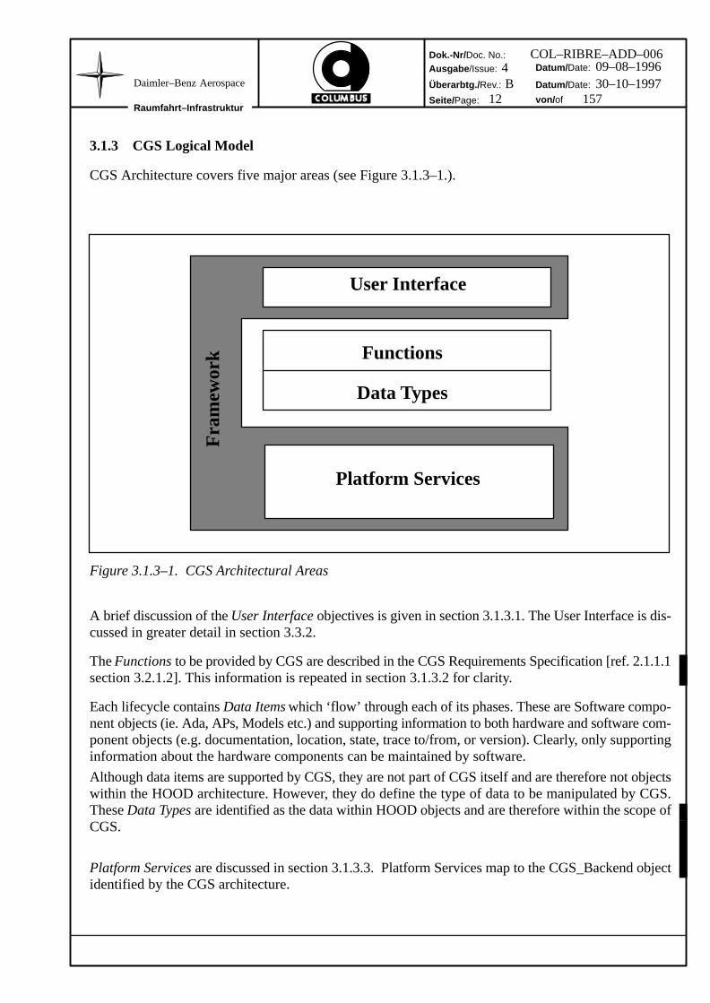
CGS Architecture covers five major areas (see Figure 3.1.3–1.).
User Interface
Functions
Data Types
Platform Services
Fra
mew
ork
Figure 3.1.3–1. CGS Architectural Areas
A brief discussion of the User Interface objectives is given in section 3.1.3.1. The User Interface is dis-cussed in greater detail in section 3.3.2.
The Functions to be provided by CGS are described in the CGS Requirements Specification [ref. 2.1.1.1section 3.2.1.2]. This information is repeated in section 3.1.3.2 for clarity.
Each lifecycle contains Data Items which ‘flow’ through each of its phases. These are Software compo-nent objects (ie. Ada, APs, Models etc.) and supporting information to both hardware and software com-ponent objects (e.g. documentation, location, state, trace to/from, or version). Clearly, only supportinginformation about the hardware components can be maintained by software.
Although data items are supported by CGS, they are not part of CGS itself and are therefore not objectswithin the HOOD architecture. However, they do define the type of data to be manipulated by CGS.These Data Types are identified as the data within HOOD objects and are therefore within the scope ofCGS.
Platform Services are discussed in section 3.1.3.3. Platform Services map to the CGS_Backend objectidentified by the CGS architecture.
Dok.-Nr/ Doc. No.:Ausgabe /Issue:
Überarbtg./ Rev.:
Seite/Page:
Datum/ Date:
Datum/ Date:
von/ ofRaumfahrt–Infrastruktur
Daimler–Benz Aerospace
13 157
COL–RIBRE–ADD–0064 09–08–1996B 30–10–1997
3.1.3.1 User Interface
CGS provides a data oriented approach to the user interface. At each (CGS supported) stage of a life-cycle, the user is offered functions relevant to preselected data.
Access to CGS is governed by a Top Level User Interface.
The objective of a user interface is to raise the levels of the following qualities:
* Security; The ability to control access to a system.
* Useability; The ability to learn and use the functionality of system.
* Manageability; The ability to deal with changes to system configurations.
The User Interface is discussed in greater detail in section 3.3.2.
Note that, following the HOOD semantic, there would be only one control object that supports the userinterface for all sub–objects, calling the Presentation services for basic window and data entry support.However the constraint to use commercial software [cf. 3.1.4.2] and the developed software within theadvanced development program [cf. 3.1.4.3] means that it is not always possible to represent user controlin the above mentioned manner.
HCI standards are needed if a common user interface is to be achieved within CGS User Interface De-sign. Where centrally provided services are not practical (e.g. where contractual interfaces of a compo-nent must be minimal), the HCI standards become even more important. Commercial Products arechosen to conform to these standards as closely as possible. The CGS User Interface design recognisesthese constraints. [see also section 3.1.4].
3.1.3.2 Functions
3.1.3.2.1 Design and Development Support
The overall Design and Development Support Function can be refined into the following three majorsubfunctions:
* SW Life Cycle Support including:
– Definition and Analysis Support for SW Requirements,
– Definition Support for SW Interface Control Documents,
– Architectural / Detailed Design Support for COLUMBUS SW,
– Coding Support for Ground SW for SUN–4/HP,
– Traceability Support (eg from ADD to SW Requirements).
* SW Management Support including:
– SW Configuration Control (eg version control of SW Items) based upon Ather-ton as the single Framework,
– SW Import/Export facilities.
* SW Documentation Handling.
Dok.-Nr/ Doc. No.:Ausgabe /Issue:
Überarbtg./ Rev.:
Seite/Page:
Datum/ Date:
Datum/ Date:
von/ ofRaumfahrt–Infrastruktur
Daimler–Benz Aerospace
14 157
COL–RIBRE–ADD–0064 09–08–1996B 30–10–1997
Software Development Support is also provided for Ground Data Items (GDIs) and Flight ConfigurationData Items (CDIs):
* Definition Support for Flight and Ground Hardware/Software Configurations,
* Coding Support for Ground and Flight APs (in UCL):
– Ground APs on CGS Standard HW and CGS Special Checkout HW (SUN–5and HP–9000/700),
– Flight APs on the standard Onboard Target Processor.
* Development support for HLCL sequences,
* Data Development Support for Ground Data and Flight Data:
– Display Development Support for Ground and Flight Displays,
– Development of Scripts written in Crew Procedure Language (CPL)
– Configuration Data Development Support for Ground and Flight related Data.
* Support to the Simulation Model Development,
* Support to the generation of the Onboard Database Image.
Generic Tool and Compiler Interfaces also provide access to Software Development Add On softwarewhich can be integrated into the Software Development environment. Add On services may include:
– Software Design Analysis,
– Static Analysis Support for COLUMBUS Ground and Flight SW,
– Ground and Flight Compilation environments,
– Dynamic Analysis Support for COLUMBUS Ground and Flight SW,
– SW Product Assurance.
3.1.3.2.2 Integration, Test and Qualification Support (Flight SW/HW Systems)
* Support to the Definition of Test Configurations,
* Support to the Set–Up of Test Sessions,
* Support to the Execution of Tests on different Test Levels,
* Support to the (Online / Offline) Evaluation of Tests.
Dok.-Nr/ Doc. No.:Ausgabe /Issue:
Überarbtg./ Rev.:
Seite/Page:
Datum/ Date:
Datum/ Date:
von/ ofRaumfahrt–Infrastruktur
Daimler–Benz Aerospace
15 157
COL–RIBRE–ADD–0064 09–08–1996B 30–10–1997
3.1.3.3 Platform Services
3.1.3.3.1 Introduction
Platform Services support CGS Applications. In order for the Applications to be able to use CGS hard-ware, a number of basic software services are required. Software that provides functions on top of thesebasic services is also required, even though this functionality is not identified in the Application specifi-cation. Such software provides the Platform Service support needed by the Applications.
Platform Services can be grouped into the following:
* Communication Services
* Database Services
* Presentation Services
* Operating System Services
* Ground Synoptic Display Services
* Central Services
The application interfaces of the Platform Services are so defined that they open the way to migratingthe applications to alternative hardware platforms [cf. 3.1.4.1].
Platform Services are supported mainly by commercial products.
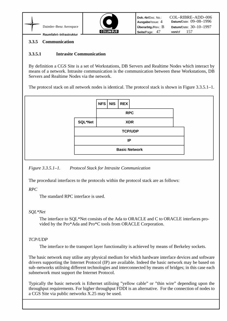
3.1.3.3.2 Communication Services
Communication Services cater for all aspects of network communications including the software re-quired to support communication protocols. This includes definitions of:
* Wide Area Networking
* Local Area Networking
* mail services
* interoperability with proprietary networks
* support for emulation of proprietary terminal devices
Details of Communication Services are discussed further in section 3.3.5.
Dok.-Nr/ Doc. No.:Ausgabe /Issue:
Überarbtg./ Rev.:
Seite/Page:
Datum/ Date:
Datum/ Date:
von/ ofRaumfahrt–Infrastruktur
Daimler–Benz Aerospace
16 157
COL–RIBRE–ADD–0064 09–08–1996B 30–10–1997
3.1.3.3.3 Database Services
Database Services cater for all aspects of the Database Management Systems that handles CGS data.This includes:
* ORACLE RDBMS system
* ORACLE support tools e.g.
– SQL*Plus
– SQL*ReportWriter
– PRO*C
– PRO*Ada
– SQL*Forms
– SQL*Loader
3.1.3.3.4 Presentation Services
Presentation Services are the basic functionality for implementing user interfaces, providing:
* a window manager/server
* a toolkit for window programming
* a toolkit for user interface prototyping
* standard window applications such as clock, etc.
3.1.3.3.5 Ground Synoptic Display (GSD) Services
GSD Services provide the basic functionality for implementing Ground Synoptic Displays, used mainlyfor Testing purposes, providing:
* graphical object/data graphic editing
* creating/managing graphical windows
* execution of graphics and windows (Synoptic Displays).
Dok.-Nr/ Doc. No.:Ausgabe /Issue:
Überarbtg./ Rev.:
Seite/Page:
Datum/ Date:
Datum/ Date:
von/ ofRaumfahrt–Infrastruktur
Daimler–Benz Aerospace
17 157
COL–RIBRE–ADD–0064 09–08–1996B 30–10–1997
3.1.3.3.6 Operating System Services
Operating System Services are the basic services identified by the POSIX standards. These include de-finitions of:
* UNIX services
* shell services
* language binding services
* administration services
* window services
* security extension services
* boot services.
Real Time OS services and a Real Time execution environment are also provided, in particular, for theexecution of Simulation Models.
3.1.3.3.7 Central Services
Central Services are provided by system software to any requesting application. These include:
* Error services
* Invocation Services
* User Administration
* Data Administration.
3.1.4 Implementation Constraints
Implementation constraints (From Requirements or Design) may be applied to one or more of the CGSConfigurations.
3.1.4.1 Open Systems
CGS needs to be an Open System.
Some commercial companies produce Open Systems. A direct consequence of the long COLUMBUSlifetime requirements is the need for a robust system that allows minimum impact with changes in tech-nology and requirements. This is a problem for any software system, so it is not surprising that standardsare continuously defined by the Software Engineering Industry. They support commercial vendors inproducing Open Systems.
Open systems are characterised by higher levels of the following qualities:
* Portability: the ability to move software between different manufactures machines. [ref.2.1.1.1 req. 4.12.4.1] (Note that software portability is considered an important objective forCOLUMBUS by ESA),
Dok.-Nr/ Doc. No.:Ausgabe /Issue:
Überarbtg./ Rev.:
Seite/Page:
Datum/ Date:
Datum/ Date:
von/ ofRaumfahrt–Infrastruktur
Daimler–Benz Aerospace
18 157
COL–RIBRE–ADD–0064 09–08–1996B 30–10–1997
* Scaleability: the ability to run the same software with acceptable performance on differentsizes of system. CGS will be available at a number of different sites, each with a configur-ation dependent upon the sites support needs. The exact definition and the installation of aCGS Configuration is performed within the Facility Projects.
* Interoperability: the ability to communicate between dissimilar systems in such a way thatthe characteristics of the system providing the service to the user are concealed. Details ofInteroperability issues are discussed in section 3.3.6.
* Upwards Compatibility: the ability to allow migration to later CGS versions withoutloosing data or requesting changes in CGS external products. For CGS databases, up-grade scripts will be provided if necessary.
CGS uses de–facto standards. Software is a relatively new Engineering discipline and a number of Stan-dards supporting the open system philosophy are not yet formally agreed by standards bodies, howevercertain standards are recognised by the industry. These de–facto standards are therefore useful guidelinesas the the future of commercial products. CGS therefore attempts to minimise the need for subsequentchanges to software products by using such de–facto standards.
3.1.4.2 Commercial Products
It is an objective of CGS design to follow the industry standards. To avoid unnecessary development,CGS design uses industry standards where they have become acceptable de–facto standards [ref. 2.1.1.1req. 4.13.1.4], thus de facto standards [cf. 3.1.4.1] are considered during the selection of CommercialProducts.
CGS Software is based on COTS products. Most have been identified in the CGS Specification [ref.2.1.1.1] and fall within the scope of the Platform Services.
3.1.4.3 Existing Developed Software
The most important constraint is to use existing software. As part of Advanced Development, consider-able work has been carried out in the functional areas of CGS. This software is therefore central to CGSand is utilised in the CGS architecture and design. CGS is built from a number of existing software prod-ucts, encompassing integrated COTS, generically developed software, tailored package software andinterface software.
For further identification of the CGS software products, refer to chapter 5.
3.1.4.4 Hardware
No hardware is provided with CGS but there is a need to specify on which hardware CGS is to execute.This is defined in the CGS requirements specification [ref. 2.1.1.1] as Implementation Constraints. CGSis designed to be independent of the underlying hardware. Details of CGS Hardware are covered furtherby section 4.1.1.
Dok.-Nr/ Doc. No.:Ausgabe /Issue:
Überarbtg./ Rev.:
Seite/Page:
Datum/ Date:
Datum/ Date:
von/ ofRaumfahrt–Infrastruktur
Daimler–Benz Aerospace
19 157
COL–RIBRE–ADD–0064 09–08–1996B 30–10–1997
3.1.4.5 Real–Time Aspects
CGS Configurations are utilised in Offline and Online environments, corresponding to the Facilities asgiven in Section 3.1.2.1.
* Offline Environments:
– Software Design and Development Facility (SDDF)
* Online Environments:
– Electrical Ground Support Equipment (EGSE)
– Software Integration & Test Environment (SITE)
For the HW / SW Integration and Qualification Test either on Subsystem or on System Level, CGS pro-vides an realtime environment. Model Images, simulating the missing Subsystem HW and/or the APMFlight Configuration environmental conditions are to be executed within a real time scale in order to re-flect the correct dynamic behaviour of the missing HW functionality. The actual execution of the On-board SW including SWRUs, APs, Configuration Data, Screen Definitions, Synoptic Displays will takeplace on the SITE. Here as well there is a need of a realtime environment to obtain correct dynamicalbehaviour of the simulated Sub/System.
The exact definition and the installation of a CGS Configuration is performed within the Facility Pro-jects.
3.1.4.6 Software Language Strategy
3.1.4.6.1 Hardware Targets
The proposed COLUMBUS Hardware targets, planned for Ada support systems, are:
* Onboard DMS target processor
* COLUMBUS ground system target 1 (SUN)
* COLUMBUS ground system target 2 (HP–UX)
The Ground Systems (HP and SUN) form part of an integrated heterogeneous environment.
Note it is also envisaged that C Language support systems will be required on some of the above, in par-ticular, for the Ground Systems. The C Language compilers and support tools can also be accessed viageneric compiler and tool interfaces (see Section 3.1.4.6.2).
3.1.4.6.2 CGS Software Development Environment Compiler Integration Concept
CGS supports the integration of additional Compiler systems (CGS Add On software) via a GenericCompiler Interface. This will enable appropriate Ground and Flight Compiler systems, as required bythe Flight System developer, to be purchased seperately from the CGS system and subsequently inte-grated. In general, these will be Ada and C Compiler systems, where C Objects can also be linked intoAda packages.
Dok.-Nr/ Doc. No.:Ausgabe /Issue:
Überarbtg./ Rev.:
Seite/Page:
Datum/ Date:
Datum/ Date:
von/ ofRaumfahrt–Infrastruktur
Daimler–Benz Aerospace
20 157
COL–RIBRE–ADD–0064 09–08–1996B 30–10–1997
The Generic Compiler interface provides a set of core Compilation functions (eg compile, link, debugetc), which are applicable to most Compiler Systems and form environment functions to those providedby the Add On Compiler. Integrated Compilers can then be invoked from within CGS and appropriateData controlled within the CGS Software Data repository for Configuration Management.
3.1.4.6.3 CGS Ground Command Languages
CGS provides a set of ground command languages, which have common denominators.
User Control Language (UCL)
UCL is used for writing Automated Procedures (APs) and UCL libraries. These are translated into ani–code by a UCL compiler and the i–code is interpreted at run time.
High Level Command Language (HLCL)
HLCL is used for writing Command sequences for interactive commanding of software applications.HLCL commands are interpreted and executed at run time. Single commands can be entered via a Com-mand Window interface to an HLCL Interpreter or may be generated by software applications.
UCL and HLCL have the same core language structure, but with particular extensions appropriate totheir use. HLCL for instance is enhanced for interactive commanding. Both languages are supported byan editor, with appropriate syntax help and editing facilities is available, the results of which are storedin the Mission Database.
Some of the software components providing COLUMBUS Command Language services are implem-ented as generic packages, instances of which are incorporated within other CGS software functions. Forinstance, HLCL Interpreter and HLCL Command Window are built into Qualification Test control soft-ware.
Dok.-Nr/ Doc. No.:Ausgabe /Issue:
Überarbtg./ Rev.:
Seite/Page:
Datum/ Date:
Datum/ Date:
von/ ofRaumfahrt–Infrastruktur
Daimler–Benz Aerospace
21 157
COL–RIBRE–ADD–0064 09–08–1996B 30–10–1997
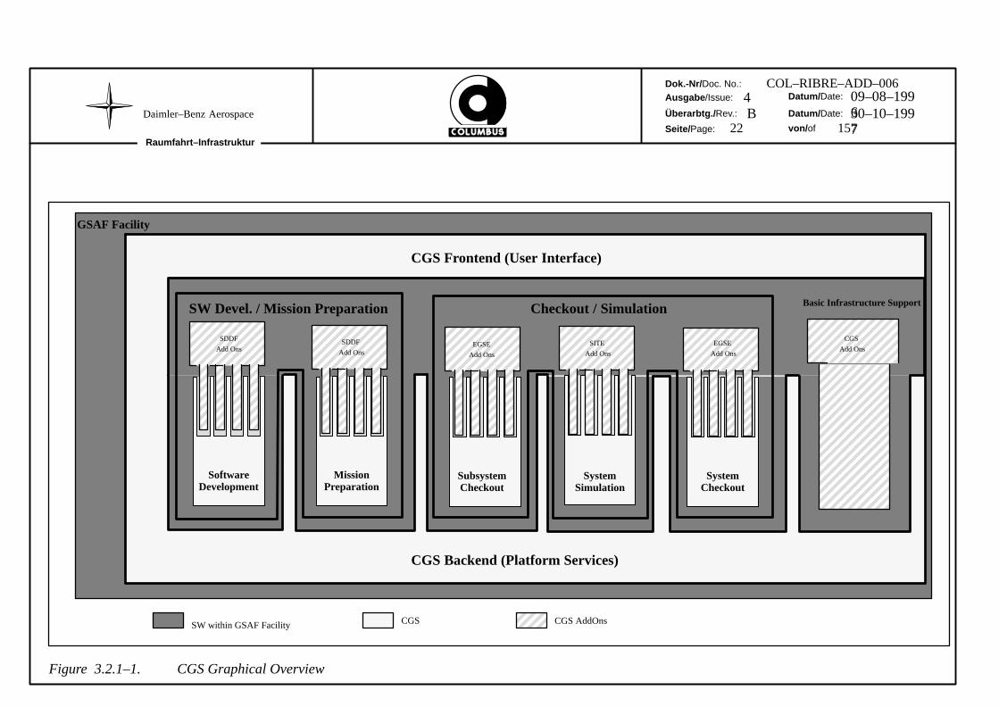
3.2 CGS Graphical Overview
3.2.1 CGS Layered Architecture
Figure 3.2.1–2 on the next page is a graphical representation of CGS. It shows that a Facility, withinwhich CGS is utilised is constructed from the following:
* CGS Backend,
* CGS Application,
* CGS Frontend.
The CGS Backend provides functionality, which is common to the Application Level ie. SW Develop-ment, Checkout etc. in order to minimize duplication of functionality.
CGS provides a ‘library’ of functions from which a framework for an Facility may be built and confi-gured. Additional Facility functionality is integrated with CGS to provide a Facility tailored to specificneeds. Functions, outside the scope of CGS, that are ‘added–On’ to CGS are termed Add Ons. Layeredarchitecture in this perspective also means that higher level SW is independent of specific details of un-derlying SW.
Although not shown on the diagram, there are interfaces between the Add Ons and the platform services.
A CGS Site is a set of Workstations, DB Servers and Realtime Nodes (i.e. Test Nodes, SimulationNodes) which interact by means of a network and which have been assigned to a single NIS Domain.A CGS Site will run a sets of CGS software corresponding to a CGS Configuration to form the softwarebasis for one of the Facilities.
A CGS Site represents a closed environment in so far as there is no sharing of data, etc. between CGSSites and there are no automatic processes for maintaining consistency between the software and dataat different CGS Sites.
Normally the network underlying the NIS Domain of a CGS Site is a LAN, although it may incorporateWAN protocols such as X.25 or ISDN/PPP.
It is possible that more than one NIS Domain coexist on the same physical network. Therefore 2 or moreCGS Sites may be collocated. Equally an NIS Domain representing a CGS Site may coexist on the samephysical network as an NIS domain which is dedicated to non–CGS activities. In both cases eachWorkstation, DB Server or Realtime Node is assigned exclusively to one of the NIS Domains. Hencealthough NIS domains may share a single underlying network each computer connected to the networkis assigned to a particular NIS Domain and thereby to a particular CGS Site.
The configuration of NIS within CGS is addressed in section 3.3.6.3.
By making the UNIX account information part of the NIS Database it is ensured that the same accountinformation is referenced from all computers within a NIS Domain. It is therefore the characteristic ofa CGS Site that a CGS user may login at any Workstation or Server within the site using the same accountname and password. User login remains possible as long as one NIS Server in the NIS Domain represent-ing the CGS Site is accessible via the network.
3.3.2 User Interface
The objective of the CGS user interface is to assist users in:
· identifying the data relevant to the work they have to do,
· identifying the function / software supporting them in their work and
· performing their work efficiently and reliable.
In establishing these objectives there is the underlying objective of preventing a user from modifyingdata for which he/she has no access rights and from using data in an incorrect, or unintended, way.
This section addresses the measures within CGS in order to fulfil these objectives.
Dok.-Nr/ Doc. No.:Ausgabe /Issue:
Überarbtg./ Rev.:
Seite/Page:
Datum/ Date:
Datum/ Date:
von/ ofRaumfahrt–Infrastruktur
Daimler–Benz Aerospace
24 157
COL–RIBRE–ADD–0064 09–08–1996B 30–10–1997
3.3.2.1 CGS Tasks
The areas of work in which CGS provides support are termed CGS tasks. With each task is associateda set of CGS software. Each set of software provides functionality designed to assist the people perform-ing the particular task.
The particular objective in defining the CGS tasks is to define each task such that
· it is performed in a well defined hardware environment and
· it utilises a well defined set of CGS software.
The following CGS tasks are identified:
System Administration
The System Administration task covers the activities performed by the system administrationteam of a company or organisation.
As defined in section 3.3.1 the extent of a CGS Site is equivalent to a NIS Domain. The SystemAdministration task includes the configuration of the computing facilities within a companyinto a network and the assignment of each node of the resulting network to a NIS Domain.Hence it is part of the System Administration task to ”create” CGS Sites.
Software Development
The Software Development task provides software support for the software development life-cycles. In particular, for Requirements Definition and Analysis and Architectural Design forall software items and follow on development support for Ground and Flight Software compo-nents, implemented in ’Ada’ and ’C’.
The concepts for this support are described in greater detail in section 3.3.8.
Mission/Test Preparation and Mission Generation
The Mission/Test Preparation task provides software support functions for the definition andmaintenance of a Mission Database in particular, for the development of Onboard and GroundTest Hardware/Software Configurations.
Further functionality provided by the Mission/Test Preparation Task includes the developmentof software and data items such as Automated Procedures, Ground and Flight Displays, Simula-tion Models, Fault Management Data and Mission Planning Data. In particular, access to thedetailed design and production/coding of such items, to follow on from appropriate Require-ments Analysis and high level design performed with the Software Development Task.
To supplement Mission Preparation, Mission Generation software and access to support soft-ware is also provided, enabling the generation of Onboard Software and Data items and the On-board Database Image.
Further information is given in Section 3.3.9, which also includes more details on the MissionDatabase structure.
Dok.-Nr/ Doc. No.:Ausgabe /Issue:
Überarbtg./ Rev.:
Seite/Page:
Datum/ Date:
Datum/ Date:
von/ ofRaumfahrt–Infrastruktur
Daimler–Benz Aerospace
25 157
COL–RIBRE–ADD–0064 09–08–1996B 30–10–1997
Test Set Up
The Test Set Up Task provides the preparation of the test Software and Data required for TestExecution during Flight SIVQ and Flight AIV activities within the EGSE or SITE. This in-cludes the distribution of Software and Data to appropriate test nodes, as defined by Test Con-figurations read from the Mission and Test Database.
The Task may be executed at any Workstation provided there is network access to the Missionand Test Database and the Nodes upon which the software and data are to be loaded.
The Test Set Up Task will be performed within the EGSE and SITE environments. It is feasiblethat the Test Session definition part of the Test Set Up Task, in particular, could be performedin parallel with an ongoing Flight AIV/SIVQ test. However, unless the User’s Workstation isself–sufficient for all disc accesses, there will be network traffic generated between theworkstation and a DB–Server. It is an operational decision whether this network traffic may betolerated, i.e. whether the parallel activity be permitted or not.
Test Execution
The Test Execution task provides functionality to support Flight SIVQ and Flight AIV activitiesdepending on the Facility within which the CGS software is executing.
In the case of Flight AIV activities, the use of an EGSE Facility to checkout, integrate and testflight hardware units and subsystems is required, where the hardware units and subsystems aretermed ’Units Under Test’ (UUTs). In the case of Flight SIVQ activities, the use of an SITE toexecute the onboard software within a simulated environment is required.
For an SITE, connections between the Simulation Computer and the DMS Breadboards, uponwhich the Flight Software is executed, are needed.
The AIV and SIVQ activities have similar configurations in that they have Test Nodes interfac-ing to the UUT or Breadboard (as appropriate) and a Workstation running the Test Executionsoftware which controls the test, loads software to the UUT or Breadboard and provides visibil-ity for downlink data.
A test is parameterised by a set of data stored in an MDB. In order to isolate an SITE or EGSEfacility during tests, it is foreseen to copy the data for tests to a second MDB which is local tothe facility; the facility may then be disconnected from the rest of the CGS site by opening abridge. The second MDB is sometimes called the Test Configuration Database (TCDB). TheMDB is prepared in advance using the Mission Preparation task and the data for a test exportedto the facility using the Data Management task.
The results of a test are stored in the Test Results Database (TRDB). A TRDB may be evaluatedupon test completion by means of the Test Data Evaluation task.
In an SITE the Onboard subsystem equipment is modelled. A Realtime execution environmentis provided for the Models and networked access via Workstation is provided for monitoringand controlling model execution.
Test Data Evaluation
The Test Data Evaluation Task provides the evaluation of the results resulting from Flight AIVor Flight SIVQ activities. The evaluation functions will operate on data stored in the TRDB.
Provided that there is network access to the data to be evaluated the task may be performed atany Workstation.
Dok.-Nr/ Doc. No.:Ausgabe /Issue:
Überarbtg./ Rev.:
Seite/Page:
Datum/ Date:
Datum/ Date:
von/ ofRaumfahrt–Infrastruktur
Daimler–Benz Aerospace
26 157
COL–RIBRE–ADD–0064 09–08–1996B 30–10–1997
If Test Data Evaluation activities are carried out in a Flight SIVQ/AIV environment, ie withinan EGSE or SITE, the data from a previous test may be evaluated in parallel with an ongoingFlight AIV/SIVQ test. However, unless the User’s Workstation is self–sufficient for all disc ac-cesses, there will be network traffic generated between the workstation and a DB–Server. It isan operational decision whether this network traffic may be tolerated, i.e. whether the parallelactivity be permitted or not.
Test Data Evaluation activities may also be carried out on the SDDF to evaluate SIVQ/AIV TestResults that have been produced by tests running on the SITE or EGSE Facilities. The Test datais tranferred from these Facilities to the SDDF and Offline test evaluation activities can be per-formed in parallel with software design and development activities.
Data Administration
The Data Administration task represents a ”utility” for the transfer of data between MDBs,TRDBs and SDE repositories. The transfer may be either between different instances of data-bases within a CGS site or between databases at different sites. In both cases the transfer con-sists of 2 explicit stages: export and import.
The data in different databases may be related as follows:
· the data parameterising a Flight AIV/SIVQ test is contained in an MDB whereasthe results are stored in a TRDB; in order to process the results access to the testdefinition in the MDB is required
· whenever Onboard SW is developed and stored in an SDE repository and needsto be integrated with data in the MDB
Hence there arises the need to coordinate the transfer of data between databases such that re-lated sets of data are transferred. This coordination is performed operationally. The provisionof a single CGS task concentrating the functions for transfer between databases does, however,serve to bundle the transfer functions required by those users responsible for performing suchtransfer.
User Administration
The User Administration Task groups into one task the allocation of the following fundamentalCGS privileges:
· the privilege to perform CM functions on an MDB,
· the privilege to nominate the users of a given MDB,
· the privilege to create projects within an SDE repository,
· the privilege to nominate the members of a given project.
The User Administration Task is distinct from System Administration Task as performed bythe system administrators and operators at a CGS site. For the purposes of user administrationit is assumed, for example, that the system administrators have already installed the users to beadministered as UNIX users.
Likewise the User Administration Task is distinct from configuration management. Indeed itis by means of the User Administration Task that the privilege to perform configuration man-agement on CGS data (i.e. MDB’s and SDE repositories) is allocated.
Dok.-Nr/ Doc. No.:Ausgabe /Issue:
Überarbtg./ Rev.:
Seite/Page:
Datum/ Date:
Datum/ Date:
von/ ofRaumfahrt–Infrastruktur
Daimler–Benz Aerospace
27 157
COL–RIBRE–ADD–0064 09–08–1996B 30–10–1997
Free Documentation
The Free Documentation task covers the use of a commercial desktop publishing software tomaintain free documents, i.e. documents which are not subject to CM control.
The software supporting this task is TPS from Interleaf Corp. and is procured within the scopeof the SDE.
3.3.2.2 User Profiles/User Roles
A user profile configures a user at a CGS site. On the one hand it encompasses basic administrative dataconcerning the user such as the user’s UNIX account name and password. On the other hand it differenti-ates each user by identifying the sets of data that the user may access, and for each set of data the oper-ations the user may perform on the data. A user profile is therefore a mechanism whereby a user is as-signed one or more user roles.
The identification of which users are permitted to access a given set of data and how they are permittedto access the hardware and data, is stored with the data itself. Consequently a user profile is a distributedset of data and major parts of a user’s profile are to be found in the databases used by the CGS tasks.
Within CGS the permission to access data and to perform sets of operations on this data is delegateddownwards from a single source (i.e. the System Administrator) through intermediate levels to the totaluser community. At each intermediate level a privileged user may release privileges on the next lowerlevel to other users. In order that a privileged user has privileges at the next lower level he/she must ex-plicitly release such privileges to himself/herself.
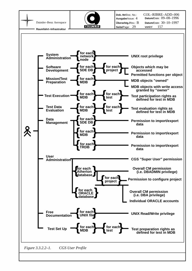
It is only as a user works with CGS, using the CGS tasks to access and possibly modify data, that a userprofile obtains its full meaning. Each of the CGS tasks references those parts of the user profile whichare relevant to itself in order to identify the sets of data that the user may access, and the sets of operationsthe user may perform. Correspondingly it provides the user with visibility only to that data which he/shemay access. Equally for each item of data it restricts the user to a permitted set of operations. Thereforethe aspects of a user profile are presented in this section on a task by task basis. Figure 3.3.2.2–1. providesan illustration of the maximum extent of a CGS user profile for a given user at a given CGS Site.
System Administration
The password for a System Administrator provides him/her UNIX root privilege and therebya level of access to the operating system which allows system administration activities to beperformed.
Software Development
The user profile defines the user’s rights of access to each data item stored in an SDE repository.These rights of access reflect closely both the structuring of data items within an SDE repositoryand the type of the data concerned. The rights of access are specific to the data in each SDErepository at a CGS Site. For this reason these rights of access are stored within each SDE re-pository.
Dok.-Nr/ Doc. No.:Ausgabe /Issue:
Überarbtg./ Rev.:
Seite/Page:
Datum/ Date:
Datum/ Date:
von/ ofRaumfahrt–Infrastruktur
Daimler–Benz Aerospace
28 157
COL–RIBRE–ADD–0064 09–08–1996B 30–10–1997
Mission/Test Preparation
The user profile defines the user’s rights to create and modify data within an MDB. In the termsof the MDB these rights are defined by the extent to which the user ”owns” the data stored with-in an MDB, and by the CM status of the data.
The concept of ownership is intimately related to the actual data and for this reason ownershipis recorded together with the data in an MDB.
Ownership is delegated downwards through the MDB tree structure. An owner at any level ofthe tree owns the data beneath that level. An owner may release the rights to create and modifydata to a further set of users. Likewise an owner may delegate the ownership of subtrees toanother user.
Each item of data stored within an MDB is identified by its type. The type of a data item deter-mines the activities that may meaningfully be performed on this item. Those activities thatmodify a data item are permitted only to the owner. In all other cases only those activities whichleave the data item unchanged are permitted.
Test Execution
This covers the user profile for the Test Execution Task within the Flight SIVQ and Flight AIVactivities. The user profile defines for each test in which the user participates the user’s particu-lar role in that test. Therefore for each test there is an associated set of profile information defin-ing the participants’ roles within that test. Since these extensions to the users’ profiles are testspecific they are stored in an MDB.
The test specific profile information for a user identifies:
· the user’s role in the test (from this is derived the set of basic functions, e.g. TestSet Up software, synoptic displays, command window, AP debugger etc. whichare provided to the user),
· the HLCL command set available to the user,
· the set of MDB data visible to the user during the test, i.e. the set of end itemsetc. for which the user may request display of the current value, the status etc.,
· the set of MDB data upon which the user may operate during the test, i.e. the setof end items the user may activate, the AP’s the user may invoke etc.,
· the user’s specific screen configuration with respect to synoptic displays, i.e.position, size, etc.
· the user’s rights to use the Simulation Model observation/control software andright to access Simulation Models (Flight SIVQ only).
Since the owner of the CDU containing the user profiles for a specific test may assign himself/herself global rights within that test he/she is effectively the Test Conductor. By the appropriatedefinition of user profiles for each test participant the Test Conductor can assign to these usersaccess rights commensurate with the user roles such as ”Test Operator”, ”UUT Specialist”, etc.
Test participation rights as defined for test in MDB
Test evaluation rights as defined for test in MDB
accessed
CGS ”Super User” permission
for eachORACLEdatabase
for eachAthertondatabase
{ }for eachproject Permission to configure project
Overall CM permission
Individual ORACLE accounts
(i.e. DBADMIN privilege)
(i.e. DBA privilege)
for eachMDB
for eachtest Test preparation rights as
defined for test in MDB{ } { }Test Set Up
Figure 3.3.2.2–1. CGS User Profile
Dok.-Nr/ Doc. No.:Ausgabe /Issue:
Überarbtg./ Rev.:
Seite/Page:
Datum/ Date:
Datum/ Date:
von/ ofRaumfahrt–Infrastruktur
Daimler–Benz Aerospace
30 157
COL–RIBRE–ADD–0064 09–08–1996B 30–10–1997
Test Data Evaluation
The user profile defines the user’s rights to evaluate the results from Flight AIV tests, FlightSIVQ tests or Model development tests. Since the Test Data Evaluation task does not modifyor delete the data on which it operates the user profile with respect to this task reduces to thepermission to store processed data back into a TRDB.
Test Set Up
The user profile defines the user’s rights to prepare and access Test Sessions for Flight AIV/SIVQ tests and also to load Test Configurations from the Mission and Test Database to partici-pating Test Nodes. This requires read/write access to the Mission and Test Database and ap-propriate permissions to load software onto Test Nodes.
Data Administration
The user profile identifies the user’s rights to import/export data between the ORACLE andAtherton BackPlane databases at a CGS Site.
User Administration
The user profile identifies the user’s rights to establish the user profile for other CGS users ata CGS Site. Conceptually CGS foresees a CGS ”Super User” who has the right to set all aspectsof the user profiles for the CGS users at a CGS Site. This Super User may release the super userrights to other named users either outright, or partially.
The CGS Super User is created by the System Administrators for the site. The CGS Super Useris the database administrator for all SDE repositories at a CGS Site (i.e. owner of the DBAD-MIN account) and the owner of all ORACLE installations. The CGS Super User does not re-quire UNIX root privilege and is responsible for the usage of CGS software only.
In practice some of the responsibilities conceptually assigned to the CGS Super User must beperformed by the System Administrators of the site. In particular where the user profile utilisesUNIX features such as root privilege and file system access rights it is the System Administra-tors, not the CGS Super User, who manages these. Likewise the System Administrators are re-sponsible for creating the NIS Domain associated with a CGS Site, creating UNIX user ac-counts, installing commercially procured software and licences etc.
Free Documentation
The user profile determines the set of UNIX files within the CGS Site that the user may (i) readand (ii) write. The user profile is therefore represented by the user’s read and write permissionswithin the UNIX filesystem.
Dok.-Nr/ Doc. No.:Ausgabe /Issue:
Überarbtg./ Rev.:
Seite/Page:
Datum/ Date:
Datum/ Date:
von/ ofRaumfahrt–Infrastruktur
Daimler–Benz Aerospace
31 157
COL–RIBRE–ADD–0064 09–08–1996B 30–10–1997
3.3.2.3 Basic User Interface Concept
CGS provides 2 classes of user interface as described hereafter.
Scrolled Screen VT 100 Type Interfaces to DB Servers and Realtime Nodes
As a basic interface for performing system administration with respect to these computers.
Window Based Interfaces to Workstations
The standard user interface to CGS User Tasks is based on a CGS desktop and, within this, theuse of graphic windowing techniques. The windows generated by this software are managedby a window manager which also executes on the user’s Workstation.
The ”look and feel” of the CGS desktop is determined by the OPEN LOOK standard for aGraphical User Interface. The ”look and feel” within windows generated by CGS developedsoftware is likewise in accordance with the OPEN LOOK standard. The ”look and feel” withinwindows generated by procured software may deviate from this standard.
The presentation of windows to a user occurs either:
· from software executing on the user’s Workstation to the graphics screen of thisWorkstation,
· from software executing on a remote Workstation to the graphics screen of theuser’s Workstation,
· or from software executing on a remote Workstation to a user at an X–terminal.
Wherever a CGS task involves software executing on a Realtime Node or a DB–Server thereis CGS software executing on a Workstation which acts as a gateway to the user. This softwareon a Workstation maintains on the one hand an interactive graphics interface to the user and onthe other hand a network connection to the software on the Realtime Node or DB–Server forthe exchange of data and commands. The software on the Realtime Node or the DB–Server isthereby freed from the need to maintain its own interface with the user.
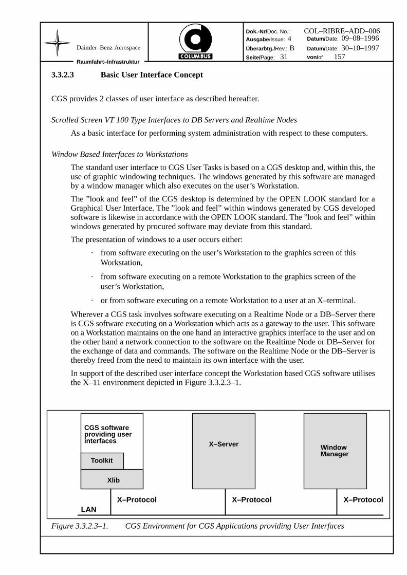
In support of the described user interface concept the Workstation based CGS software utilisesthe X–11 environment depicted in Figure 3.3.2.3–1.
Xlib
X–Server WindowManager
X–Protocol X–Protocol X–ProtocolLAN
Toolkit
CGS softwareproviding userinterfaces
Figure 3.3.2.3–1. CGS Environment for CGS Applications providing User Interfaces
Dok.-Nr/ Doc. No.:Ausgabe /Issue:
Überarbtg./ Rev.:
Seite/Page:
Datum/ Date:
Datum/ Date:
von/ ofRaumfahrt–Infrastruktur
Daimler–Benz Aerospace
32 157
COL–RIBRE–ADD–0064 09–08–1996B 30–10–1997
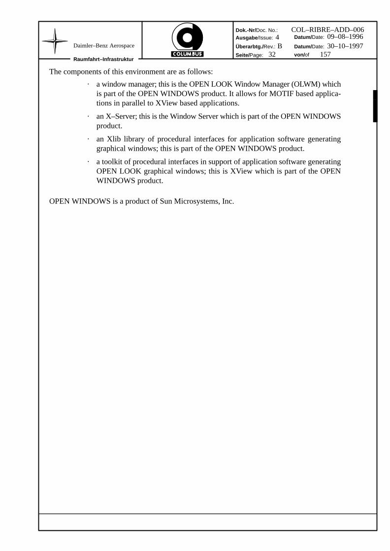
The components of this environment are as follows:
· a window manager; this is the OPEN LOOK Window Manager (OLWM) whichis part of the OPEN WINDOWS product. It allows for MOTIF based applica-tions in parallel to XView based applications.
· an X–Server; this is the Window Server which is part of the OPEN WINDOWSproduct.
· an Xlib library of procedural interfaces for application software generatinggraphical windows; this is part of the OPEN WINDOWS product.
· a toolkit of procedural interfaces in support of application software generatingOPEN LOOK graphical windows; this is XView which is part of the OPENWINDOWS product.
OPEN WINDOWS is a product of Sun Microsystems, Inc.
Dok.-Nr/ Doc. No.:Ausgabe /Issue:
Überarbtg./ Rev.:
Seite/Page:
Datum/ Date:
Datum/ Date:
von/ ofRaumfahrt–Infrastruktur
Daimler–Benz Aerospace
33 157
COL–RIBRE–ADD–0064 09–08–1996B 30–10–1997
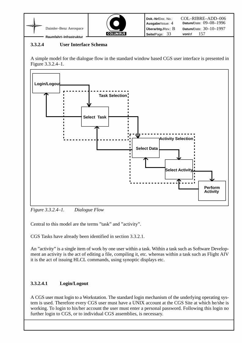
3.3.2.4 User Interface Schema
A simple model for the dialogue flow in the standard window based CGS user interface is presented inFigure 3.3.2.4–1.
PerformActivity
Login/Logout
Task Selection
Activity Selection
Select Activity
Select Data
Select Task
Figure 3.3.2.4–1. Dialogue Flow
Central to this model are the terms ”task” and ”activity”.
CGS Tasks have already been identified in section 3.3.2.1.
An ”activity” is a single item of work by one user within a task. Within a task such as Software Develop-ment an activity is the act of editing a file, compiling it, etc. whereas within a task such as Flight AIVit is the act of issuing HLCL commands, using synoptic displays etc.
3.3.2.4.1 Login/Logout
A CGS user must login to a Workstation. The standard login mechanism of the underlying operating sys-tem is used. Therefore every CGS user must have a UNIX account at the CGS Site at which he/she isworking. To login to his/her account the user must enter a personal password. Following this login nofurther login to CGS, or to individual CGS assemblies, is necessary.
Dok.-Nr/ Doc. No.:Ausgabe /Issue:
Überarbtg./ Rev.:
Seite/Page:
Datum/ Date:
Datum/ Date:
von/ ofRaumfahrt–Infrastruktur
Daimler–Benz Aerospace
34 157
COL–RIBRE–ADD–0064 09–08–1996B 30–10–1997
After successful login a CGS desktop is automatically displayed on the user’s Workstation. The desktopprovides:
· a standard repertoire of windows such as clock, console window, user statuswindow (i.e. a display of user account name, user group etc.)
· access to a pop–up menu for standard system features such as freeze screen,create shell etc.,
· a task selection menu, either as a standard window or a pop–up menu, and aspresented hereafter.
3.3.2.4.2 Task Selection
The task selection menu enables a user to select a task to be performed, and the data context within whichthe task is to be performed.
Behind each task is a well–defined subset of CGS software. Following selection of a task the CGS soft-ware associated with this task is activated. This software provides the user interface to the task.
Data Selection
For most tasks there is an underlying set of data. Within CGS the underlying sets of data aremanaged by:
· Mission Database (MDB),
· Software Development Environment (SDE) data repository,
· and Test Results Database (TRDB).
All these are implemented by means of the ORACLE RDBMS, with the exception of the SDEdata repository which is implemented by means of the Atherton BackPlane.
Within those CGS Configurations/Facilities that an SDE operates, there will necessarily be anAtherton Backplane and at least one ORACLE database.
Note that Software Development Add On software integrated via the Generic Tool interface,may also have data stored in their own ORACLE databases eg for Product Assurance data.
At a CGS site there may be several instances of ORACLE and Atherton BackPlanes, eg:
· to decouple an integration or simulation facility from the office environment,
· to decouple flight software development from ground software development,
· to evaluate new releases (of ORACLE or Atherton BackPlane),
The number of instances, and the databases etc. actually present under each instance, is a sitespecific consideration.
To support multiple instances of ORACLE, eg so that in the same Configuration, a User canswitch from an SDE ORACLE instance (eg TRIT) to a Mission/Preparation ORACLE instance(eg MDA), appropriate environmental variables are set on invocation of the SDE software andreset on exiting. These are defined Offline in system configuration or UNIX script files.
Using the described mechanism the user may invoke, for example, 2 parallel instances ofMission/Test Preparation, each referencing a different MDB. This is done by invoking 2 separ-
Dok.-Nr/ Doc. No.:Ausgabe /Issue:
Überarbtg./ Rev.:
Seite/Page:
Datum/ Date:
Datum/ Date:
von/ ofRaumfahrt–Infrastruktur
Daimler–Benz Aerospace
35 157
COL–RIBRE–ADD–0064 09–08–1996B 30–10–1997
ate instances of the task, each referencing a different ORACLE instance. This use of CGS may,for example, help in comparing the definition of the same end item in different MDBs.
Note, however, that one task may not simultaneously reference 2 different ORACLE instances.It is therefore not possible, for example, to perform Flight AIV activities with an MDB andTRDB stored under different instances of ORACLE.
Task Selection
The identification of CGS user tasks results in a relatively small list, so obviating the need fora large multiple level menu.
A file in the user’s home directory identifies the list of tasks to be shown to the user. The usermay edit this file and so remove tasks which are not of relevance to him/her. Indeed a user mayalso edit this file to introduce additional non–CGS tasks.
The activation of the software implementing each task occurs by means of the software imple-menting the CGS desktop. The task selection menu is a feature of the CGS desktop and is ac-cessible whenever application windows do not fully obliterate the desktop. Hence it is possibleto invoke more than one task in parallel.
The software invoked by means of the task selection menu provides the task level user interface.It is therefore this software which controls the extent to which activities are performed in paral-lel and where within the network activities are executed.
3.3.2.4.3 Activity Selection
It is a fundamental assumption that each task controls the user both with respect to the selection of dataand with respect to the activities performed on selected data.
The precondition for controlling the selection of data by a given user, and determining the activities thatthis user may perform on any selected data, is the user profile defining the user’s privileges with respectto the data concerned. Since each task has its own distinct purpose the information to be embedded ina user profile is task specific. The task specific information embedded in a user profile has already beenpresented in section 3.3.2.2.
Before a user may execute one or more activities within a task a context in the underlying data must beestablished. A context may be either a single data entity or a structured set of data. By reference to theuser profile the task may then determine exactly which activities the user may perform on the selecteddata.
Data Selection
Before the execution of an activity within a task the data applicable to the activity must be estab-lished. The data selection menu serves to assist the user in the selection of the data on whichhe/she wishes to work.
The term ”data selection menu” is used freely; the underlying data for a task, and the extent towhich this is presented to the user in the data selection menu, is task specific.
Dok.-Nr/ Doc. No.:Ausgabe /Issue:
Überarbtg./ Rev.:
Seite/Page:
Datum/ Date:
Datum/ Date:
von/ ofRaumfahrt–Infrastruktur
Daimler–Benz Aerospace
36 157
COL–RIBRE–ADD–0064 09–08–1996B 30–10–1997
Activity Selection
The task level user interface guides the user in the selection of one or more activities to be per-formed with respect to the previously selected data.
The nature of the selected data determines the set of activities which are meaningful. The userprofile, the CM status of the data etc. determine which of this set of activities are permitted tothe current user, and where and how any data generated is to be retained. Again this representsa task specific extension to the user profile. These extensions have already been presented insection 3.3.2.2.
3.3.2.5 Help Facilities
Hereafter a distinction is made between context sensitive and context independent help mechanisms.Since the man machine interface provided by CGS is based primarily on interactive window techniquesthe emphasis is upon the provision of a powerful interactive context sensitive help mechanism.
Context Sensitive Help Mechanism
The basic mechanism within CGS for providing interactive help information is that of theOPEN LOOK Graphical User Interface. The help features provided by procured software with-in CGS may deviate from this standard.
The OPEN LOOK help mechanism offers the possibility of defining a help text for each ”el-ement” of a window. Elements are the basic units in an OPEN LOOK window such as buttons,texts, sliders, gauges, lists, etc.
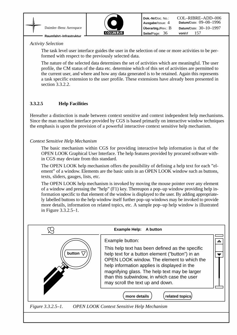
The OPEN LOOK help mechanism is invoked by moving the mouse pointer over any elementof a window and pressing the ”help” (F1) key. Thereupon a pop–up window providing help in-formation specific to that element of the window is displayed to the user. By adding appropriate-ly labelled buttons to the help window itself further pop–up windows may be invoked to providemore details, information on related topics, etc. A sample pop–up help window is illustratedin Figure 3.3.2.5–1.
Example button:
This help text has been defined as the specifichelp text for a button element (”button”) in an
magnifying glass. The help text may be largerthan this subwindow, in which case the usermay scroll the text up and down.
button
more details related topics
Example Help: A button
OPEN LOOK window. The element to which thehelp information applies is displayed in the
Figure 3.3.2.5–1. OPEN LOOK Context Sensitive Help Mechanism
Dok.-Nr/ Doc. No.:Ausgabe /Issue:
Überarbtg./ Rev.:
Seite/Page:
Datum/ Date:
Datum/ Date:
von/ ofRaumfahrt–Infrastruktur
Daimler–Benz Aerospace
37 157
COL–RIBRE–ADD–0064 09–08–1996B 30–10–1997
Context Independent Help Mechanism
The CGS User Manual is provided as an HTML document. The document may be browsed byany commercial browser(e.g. Netscape). The user may navigate via the hyperlinks to thechapter of interest.
Note that other On Line help may be provided by Commercial Products as appropriate.
Dok.-Nr/ Doc. No.:Ausgabe /Issue:
Überarbtg./ Rev.:
Seite/Page:
Datum/ Date:
Datum/ Date:
von/ ofRaumfahrt–Infrastruktur
Daimler–Benz Aerospace
38 157
COL–RIBRE–ADD–0064 09–08–1996B 30–10–1997
3.3.3 Standard Test Approach
3.3.3.1 Introduction
The standard test approach as defined in this section can be applied to any CGS Configuration. The scopeof each of the addressed areas will differ considerably between say, a piece of Ada Code and its Produc-tion Environment, and a Flight Software Subsystem and its Test Environment
Operationally CGS functionality is logically partitioned into two systems. The off–line system supportsthe preparation and management of software and configuration data. The on–line system supports theintegration, checkout and qualification testing of hardware together with software.
The Item Under Test is the hardware or software being tested (e.g. UUT like Onboard SW or entire FlightConfiguration). This may be a ground or flight component.
The Test Harness is the framework of software, hardware and data especially produced for testing theItem under Test. It consists of Test Controllers, Test Stubs and Test Data that are needed for the test.
The Test Controllers are the software and hardware that control execution of a test. Software test controlcan range from Ada Tool support to CGS Products: HCI/TES/TSCV. Hardware Test Control can rangefrom a variable resistor to the EGSE Hardware Control System.
Test Stubs are the software and hardware that provide dummy functionality for components not yet avail-able (software ‘stubs’ and hardware ‘dummies’). Software stubs can range from empty software mod-ules through complex Simulation Models to a qualified flight software subsystem. Hardware dummiescan range from a short circuit through an EGSE system to qualified flight hardware subsystem.
CGS Add Ons [c.f 3.1.2.3] are required to provide the specific interfaces to the Unit under Test (e.g. SASor CMAS).
System Hardware provides the platform on which both the On–line and Off–line environments execute.For product level production these are usually the same hardware with specialist hardware labelled CGShardware add–ons. For system testing these platforms are significantly different.
CGS is providing access to the Item Under Test via the Test Harness. It allows to control the test stubsas well as the Item Under Test. CGS visualizes the state of the Item Under Test, the test harness, the CGSAdd Ons, the test stubs and the System Hardware. It allows to stimulate the Item Under Test as well asthe Test Stubs (e.g. Simualtion Models) and to monitor the reaction to this stimulation. CGS logs all acti-vities during a test and records the data generated for later evaluation. Finally, CGS provides tools forthis evaluation process.
Off–line and on–line activities place different requirements on the hardware and system software. In par-ticular the on–line activities require “real–time” (e.g. deterministic response times, pre–emptive sched-uling) characteristics.
Dok.-Nr/ Doc. No.:Ausgabe /Issue:
Überarbtg./ Rev.:
Seite/Page:
Datum/ Date:
Datum/ Date:
von/ ofRaumfahrt–Infrastruktur
Daimler–Benz Aerospace
39 157
COL–RIBRE–ADD–0064 09–08–1996B 30–10–1997
3.3.3.2 Columbus SIVQ and AIV Life Cycle Support
3.3.3.2.1 General Design Goals for the CGS SIVQ/AIV Software
There are a number of Design Goals for CGS software, involved in SIVQ/AIV operations.
Vertical Commonality
Where possible, the same test system is used for different test levels eg from Subsystem level toSystem level.
A test object oriented user interface allows for execution of tests independently of the actual testsystem configuration, eg an Automated Procedure shall be executed (without change) on differenthardware or system configurations.
Transparent access to the standard services of the system is provided with the use of logical names(”pathnames”) to refer to enditems.
Open Architecture
Additional Hardware and Software Units can be integrated into a test system, thus meeting differ-ent requirements coming from a variety of Users and test objects (UUT: Unit Under Test).
Integrated Toolset
Integrated tools enable Definition, Execution/Monitoring and Evaluation of a Test.
3.3.3.2.2 Design Goals for Test Execution Support
CGS Test Execution software functions can be duplicated and executed by different processors, ie, theyform a distributed software system. The software system required can be tailored to different configur-ations, which includes different numbers of Test Nodes as well as Workstations. Basic configurationsare also possible, ie sufficient for specific tests or relatively simple test objects not requiring a complextest system.
For each such test processor generic functions are applicable that allow for development of a basic Soft-ware system which can be extended for each specific test application by adding Test specific Hardware/Software. Such a system must be also configurable to support an overall Element Configuration Testwhere all ’simple’ test objects are combined to a complex test object with a large amount of data to bemonitored in parallel.
3.3.3.2.3 Design Goals for Test Evaluation Support
Test Evaluation software enables the following:
– Evaluation of data online during test operation,
– Evaluation of data generated in previous tests and for comparison of different test sessions,
3.3.3.2.4 Design Goals Regarding the Human Computer Interface (Test ExecutionControl SW)
The CGS Test Control software conforms with the Columbus HCI Standards which are based on theOpen–Look standards. A high resolution coloured graphical User Interface is provided, driven by amouse and a keyboard at computer workstations.
A graphical view to the UUT and EGSE, allows for interactive control via graphical symbols. It providesa ’safe’ environment for different Users with specific User environments, specific User authorisation andaccess to dedicated User functions.
3.3.3.2.5 Fault Detection and Isolation during AIV/SIVQ operations
Internal Errors
Internal software errors, generated by CGS Test Execution software are displayed to the UserWorkstation and logged in the Test Results Database. Information provided may include origin,type and information for isolation or recovery. Some errors may be corrected by operator interven-tion, more serious errors result in a controlled shutdown of the Test Execution software.
Use of the CGSI provided Error Message services is made for appropriate error conditions, egwhen interfacing to other software packages, system services etc.
UUT/EGSE errors and User Defined Error Handling
The User can program handling of specific error situations for UUT and EGSE devices, eg:
– acquiring sensor values and device status data,
– defining ’derived values’ dedicated to each ’error diagnosis’,
– programming the derived values according to the state of UUT/EGSE sensors,
– generating exception messages on change of derived values,
– starting of AP on change of derived values.
3.3.3.3 Distributed Configuration Concepts
The CGS software for SIVQ/AIV operations is divided into services for Test Session definition, TestExecution/Control and Test Evaluation.
Central Database repositories provide storage and management of all prepared tables, test results andinformation supporting the integration activities. In particular a derivative of the Mission Database pro-vides a Test Configuration Database.
The SIVQ/AIV software design is based on the concept of logical nodes which might be mapped tophysical processors in a distributed environment. A node is not necessarily a separate computer systemand several nodes can be present in one computer system. A test system comprises a variable numberof nodes according to the functional needs of the tests. A test system further comprises a variable numberof computers (processors) according to the performance needs of the test.
Dok.-Nr/ Doc. No.:Ausgabe /Issue:
Überarbtg./ Rev.:
Seite/Page:
Datum/ Date:
Datum/ Date:
von/ ofRaumfahrt–Infrastruktur
Daimler–Benz Aerospace
41 157
COL–RIBRE–ADD–0064 09–08–1996B 30–10–1997
There are 3 types of nodes involved in SIVQ/AIV operations.
Workstation Nodes
For a Workstation node, the User Interface functions for controlling the execution of Tests are pro-vided. This includes driving of windows and interactive dialogs. This software is available via theCGS Top Level User Interface in particular the Test Set Up, Test Execution and Test Evaluationtasks. (ie CGS Products, TSCV, TES and TEV).
In particular, during Test Execution, messages and dynamic display updates are distributed to andfrom the Workstation Nodes to and from the execution resources.
Test Nodes
For a Test node, the Standard Services required during test configuration/execution such as moni-toring, command handling etc, are implemented by the Test Execution Software (TES) product.
There are two types of test nodes:
– Local Test Nodes that provide only local monitoring
– One Global Test Node providing the overall monitoring of the system (MTP).
Database Server Node
This node provides data services such as DBMS, logging/archiving management, printing serviceetc. The structure of this node is different from the others as it does not have a service requestingpart, but only a service provider part. Note that Test Configuration DB and Test Results DB ser-vices are provided by Database Server nodes.
From the allocation of nodes to processors, the following configurations can be derived:
– the Standalone Configuration
This configuration comprises one of each node type, i.e. a Workstation, a Test node and a Servernode. These nodes reside on two computers: one executing the test node and the other executingthe Workstation node and the DB Server node.
– the Distributed Configuration
This configuration includes one DB Server node, several (up to 32) test nodes and several (up to32) workstations. Each node will then probably reside on one computer, but combining severalnodes to one computer is possible. Note: The combination of two nodes of the same type (e.g. twotest nodes) on the same computer is not supported.
Fig. 3.3.3–1 shows the CGS Architecture required to support SIVQ/AIV activities and its main compo-nents that can be configured to the different Hardware systems to allow subsystem level checkout as wellas overall system level checkout (Fig. 3.3.3–2). Note that software components such as Platform services(UNIX, RDBMS etc) are not shown in the diagrams.
Note that in Fig. 3.3.3–1 the Mission Database Application product (MDA) is shown. This representsthe software that is used to define the Ground Test Hardware/Softare Configurations and provides theTest Configuration Database (See 3.3.9 for further details).
Dok.-Nr/ Doc. No.:Ausgabe /Issue:
Überarbtg./ Rev.:
Seite/Page:
Datum/ Date:
Datum/ Date:
von/ ofRaumfahrt–Infrastruktur
Daimler–Benz Aerospace
42 157
COL–RIBRE–ADD–0064 09–08–1996B 30–10–1997
TES
I/Fto UUT
MDA
TEV
HCI
to UUT
Test node = one computer
Workstation = one Computer
DB
S
TSCV
Figure 3.3.3–1: CGS Test Execution software Architecture
to UUTTwo or moreTest nodes
Database server node = separate computer
= separate computers
LAN
Two or more workstation nodes= separate computers
Figure 3.3.3–2: CGS Test Software Distribution to Nodes
Dok.-Nr/ Doc. No.:Ausgabe /Issue:
Überarbtg./ Rev.:
Seite/Page:
Datum/ Date:
Datum/ Date:
von/ ofRaumfahrt–Infrastruktur
Daimler–Benz Aerospace
43 157
COL–RIBRE–ADD–0064 09–08–1996B 30–10–1997
3.3.3.4 Implementation of Test Languages
To support SIVQ/AIV operations, CGS Test software uses components of the COLUMBUS LanguageSystem (CLS), in particular the UCL (User Control Language) and HLCL (High Level Command Lan-guage). For further information on CLS, refer to Section 3.1.4.6.3.
3.3.3.4.1 Use of the User Control Language (UCL)
UCL is defined as a set of Test object or Test system oriented commands together with a set of controlcommands allowing specification of automatic procedures with conditional execution. (UCL is used forboth Onboard and Ground purposes).
UCL allows for definition of Ground Test Automated Procedures (GTAPs) that may be activated by aninteractive command and can call other GTAPs. Each GTAP is compiled offline during test preparationby the UCL Compiler. This generates an intermediate language format called i–Code. This is interpretedby the UCL Interpreter called by the Test Execution Software.
UCL supports the calling of general UCL Library routines. Such libraries may be extended by Test Nodespecific routines to implement Test Node dependent statements in UCL. A call to such a library routineis nevertheless defined in a definition module and imported to the UCL compiler.
A CGS User involved in Testing operations will be able to issue interactive commands, from theWorkstation, to distributed test software via appropriate User interaction methods such as windows,menus, dialog boxes etc. These commands encompass UCL statements and other Workstation or Testspecific commands which together form the High Level Command Language (HLCL).
HLCL sequences can be defined by the User (offline) and analysed by the receiving software using theHLCL interpreter. The HLCL Interpreter will access the Test Configuration Database (ie instantiationof the Mission Database) to obtain sequences of HLCL commands.
In particular, HLCL supports the invocation of GTAPs in any test node, thus establishing a further levelof automation in the system as well as interactive access to each test node.
3.3.3.4.2 Command Authorisation
During CGS Test operations ’commands’ are generated from different sources. The Operator atWorkstations can enter an HLCL command, a UCL GTAP or application software within a test node mayrequest the execution or finally the command may be originate from a remote node. All commands shallbe authorized on two levels:
Each CGS User can be identified for Test Execution commands. A predefined set of privileges isallocated to the User which define execution rights for a limited set of commands only. DuringHLCL Command Analysis (prior to interpretation) the command is checked for user authorisationand the command is refused if it is not contained in the allocated set.
A second level of authorisation exists associated with the data (in the MDB) itself. At this leveleach End Item command (each input to a stimuli device or a TC command) is checked to see ifit was previously inhibited or not. Command inhibiting is performed by another command, withappropriately assigned privileges.
Figure 3.3.3–3 shows the principle of the command execution within CGS.
Dok.-Nr/ Doc. No.:Ausgabe /Issue:
Überarbtg./ Rev.:
Seite/Page:
Datum/ Date:
Datum/ Date:
von/ ofRaumfahrt–Infrastruktur
Daimler–Benz Aerospace
44 157
COL–RIBRE–ADD–0064 09–08–1996B 30–10–1997
Test node = one computerWorkstation = oneComputer
HLCL Interactive Command Authorization on Command
Enditem Command
UCL I–Code Interpreter
User Privileges
TC/Stimuli
UUT
User
Authorization on InhibitStatus
Authorization on EnditemCommand PrivilegesCommand Inhibit
(UCL Commands) (HLCL Commands)
Figure 3.3.3–4: Principle of Command Authorization during Test Execution
3.3.3.5 Extendability of CGS Test Execution software components to the User Needs
COLUMBUS Subsystems, Orbital Replaceable Unit (ORU) and Element Configurations will have sig-nificant differences in providing test interfaces, CGS does not aim to include all these interfaces and toimplement all the processing required for them. Rather CGS provides a flexible application software in-terface that can be used by each User (i.e. Test Node or EGSE manufacturer) to implement the respectiveinterfaces and processing software which runs on the same Node as the CGS software and uses CGSTesting services.
To allow a User to use the Test Monitoring, Automatic Procedure capabilities and User Interface provi-sions (Display, Commanding etc) of CGS and also for the support of data retrieved from / sent to nonstandard interfaces, CGS provides the ”Data Interface Application” service. This service allows forprovision of data as Acquisition Data Units (ADUs) to the CGS Test Monitoring software as well as forgeneration of data items (commands/stimuli) statements and delivery as standard Generation Data Units(GDUs) to Ada applications which then interface to specific front end devices.
Dok.-Nr/ Doc. No.:Ausgabe /Issue:
Überarbtg./ Rev.:
Seite/Page:
Datum/ Date:
Datum/ Date:
von/ ofRaumfahrt–Infrastruktur
Daimler–Benz Aerospace
45 157
COL–RIBRE–ADD–0064 09–08–1996B 30–10–1997
Figure 5.2.1.4–1 shows a possible Hardware/Software configuration for a Test Node (Test node), indi-cating the possible extensions of CGS Test software to achieve the Test Node tasks.
IEEE Bus
HP3852
IEEE BusController
IEEE BusDriver
GDUADURequest
ADU
SAS ( SpecialApp. SW IFHP 3852 )
ETHERNET
ETHERNETController
ETHERNETDriver
SAS Ethernet
GDUADU Request
ADU
SAS
CGS Test Execution SW (TES)
MeasurementsStimuli
CommercialEquipment
OB LAN
Data Aquisition, Data Processing (e.g. including ADU Generation)
FEE
FEE Message
Eng.Values
GDUADURequest
ADU
API APIAPI
SAS IEEE Device 2
IEEE Device 2IEEE Device n
Part of CGS SW Delivery User SW and HW and commercial SW and HW
SAS IEEE Device n
FEE Message
(FEE Driver)
Figure 3.3.3–5: Test Node (Test Node) with CGS and Extensions (Example)
Dok.-Nr/ Doc. No.:Ausgabe /Issue:
Überarbtg./ Rev.:
Seite/Page:
Datum/ Date:
Datum/ Date:
von/ ofRaumfahrt–Infrastruktur
Daimler–Benz Aerospace
46 157
COL–RIBRE–ADD–0064 09–08–1996B 30–10–1997
3.3.4 Security
CGS provides inherent security by the provision of security features in the system software and by theprovision of guidelines for the configuration of the CGS hardware and system software.
Operating System Security
The UNIX operating systems used within CGS achieve the C2 level of security defined by theUS DoD. The security associated with C2 exceeds that normally associated with UNIX in thefollowing ways:
· Password files are hidden and protected against access by non–authorised users.
· Audit trails can be compiled. These can be selectively enabled to monitor spe-cific users or operations.
It is a site specific consideration how the security features of the operating system are exploitedto achieve a secure, or insecure, environment. At any given CGS Site it would be feasible, forexample, to give all Users UNIX ’root’ privilege, this is of course not recommended.
Access from External Systems
Whenever a CGS Site is equipped with a WAN connection via a public network it is renderedopen to misuse by the full range of users with access to this WAN. The inherent security of aCGS is maintained by the use of a Mail Server as described in section 3.3.5.2.
Operational security is provided by the security features within the CGS software for each of the CGStasks defined in section 3.3.2.1.
User Guidance
As described in section 3.3.2.2 a CGS user profile determines what the user may, or may not,do, when, and with which data. Security is provided by controlling for each aspect of a user pro-file exactly who is permitted to establish the profile contents.
Protected Environment for Flight AIV/SIVQ
The Workstations, DB Servers and Realtime Nodes within a CGS Site interact by means of anetwork. A CGS Site is therefore influenced by network traffic resulting from network nodesconnected to the network but not belonging to the CGS Site itself. Equally a CGS Site is opento login from any node or system connected to the network.
In order to isolate an EGSE, SITE or a SDDF from such influences it is recommended to isolatesuch CGS Sites from other networks by means of a bridge. By opening the bridge during a testsession it is ensured that the test environment is not impaired by the network traffic generatedoutside of the CGS Site itself. Further, Offline Test Evaluation can be performed on the SDDFto avoid influencing AIV/SIVQ activities.
Integrated Configuration Management
For more details please refer to section 3.3.8.
Dok.-Nr/ Doc. No.:Ausgabe /Issue:
Überarbtg./ Rev.:
Seite/Page:
Datum/ Date:
Datum/ Date:
von/ ofRaumfahrt–Infrastruktur
Daimler–Benz Aerospace
47 157
COL–RIBRE–ADD–0064 09–08–1996B 30–10–1997
3.3.5 Communication
3.3.5.1 Intrasite Communication
By definition a CGS Site is a set of Workstations, DB Servers and Realtime Nodes which interact bymeans of a network. Intrasite communication is the communication between these Workstations, DBServers and Realtime Nodes via the network.
The protocol stack on all network nodes is identical. The protocol stack is shown in Figure 3.3.5.1–1.
XDR
TCP/UDP
IP
SQL*Net
NFS NIS REX
RPC
Basic Network
Figure 3.3.5.1–1. Protocol Stack for Intrasite Communication
The procedural interfaces to the protocols within the protocol stack are as follows:
RPC
The standard RPC interface is used.
SQL*Net
The interface to SQL*Net consists of the Ada to ORACLE and C to ORACLE interfaces pro-vided by the Pro*Ada and Pro*C tools from ORACLE Corporation.
TCP/UDP
The interface to the transport layer functionality is achieved by means of Berkeley sockets.
The basic network may utilise any physical medium for which hardware interface devices and softwaredrivers supporting the Internet Protocol (IP) are available. Indeed the basic network may be based onsub–networks utilising different technologies and interconnected by means of bridges; in this case eachsubnetwork must support the Internet Protocol.
Typically the basic network is Ethernet utilising ”yellow cable” or ”thin wire” depending upon thethroughput requirements. For higher throughput FDDI is an alternative. For the connection of nodes toa CGS Site via public networks X.25 may be used.
Dok.-Nr/ Doc. No.:Ausgabe /Issue:
Überarbtg./ Rev.:
Seite/Page:
Datum/ Date:
Datum/ Date:
von/ ofRaumfahrt–Infrastruktur
Daimler–Benz Aerospace
48 157
COL–RIBRE–ADD–0064 09–08–1996B 30–10–1997
3.3.5.2 Intersite Communication
Intersite communication is the communication between a CGS Site and another site, regardless of theother site being a CGS Site or not.
CGS supports communication to and from a CGS Site as follows:
· by means of magnetic storage media (i.e. tapes, etc.); the provision of this meansis routine and is not addressed further.
· via Ethernet LAN connections
· via X.25 WAN connections
The protocols supported are TCP/IP, DecNet and SNA.
The intersite communication functions supported are:
· file transfer
· remote login
File Transfer
CGS supports the transfer of files between CGS Sites under manual control. This means thatdata stored in a CGS database such as the Mission Database (MDB) or the S/W DevelopmentRepository must first be exported from the database and made available as one or more files.The file, or files, are then transferred to the target CGS Site. Finally the data is imported fromthe transferred files to CGS databases at the target CGS Site.
File transfer is effected by means of standard network utilities such as FTP and RCP. The char-acteristic of these utilities is that the user must know the name and password of an account onthe remote site; in addition the account at the remote site must possess read privilege (R) forfiles to be read and write privilege (W) for areas of the target file system which are to be(over)written.
Remote Login
CGS provides UNIX remote login and remote shell facilities. Hence a CGS user can login re-motely to any sites supporting this facility, be they CGS Sites or not.
CGS provides terminal emulation of VT100 devices over DecNET By means of this facilitya user can perform login on connected Decnet systems.
CGS provides terminal emulation of IBM 3270 devices over SNA. By means of this facilitya user can perform login on connected SNA systems.
WAN connections via a public network render a CGS Site open to misuse. Therefore it is recommendedto establish WAN connections via a Mail Server as described below.
Dok.-Nr/ Doc. No.:Ausgabe /Issue:
Überarbtg./ Rev.:
Seite/Page:
Datum/ Date:
Datum/ Date:
von/ ofRaumfahrt–Infrastruktur
Daimler–Benz Aerospace
49 157
COL–RIBRE–ADD–0064 09–08–1996B 30–10–1997
Mail Server
A Mail Server consists of a standalone workstation connected to a CGS Site by means of a LANconnection and to external sites, public networks, etc. by means of an X.25 WAN connection.The Mail Server is not part of the CGS Site itself and therefore not within the NIS Domain asso-ciated with the CGS Site.
The Mail Server may be any UNIX workstation supporting a TCP/IP interface to the LAN ofthe given CGS Site. Typically the Mail Server is a CGS Workstation which, in order to preserveits independence from the CGS Site, is equipped with its own disc(s). The operating system ofthe Mail Server exhibits, ideally, a high level of security; in the case of a CGS Workstation aversion of UNIX achieving the B1 rating of the DoD is available. For yet greater security theconnection between the Mail Server and the WAN may be routed via a ”security box” whichrestricts connections to a preconfigured set of call numbers.
The Mail Server is open to login via its WAN connection. By appropriate configuration of theuser accounts on the Mail Server the functions available to these user accounts may be re-stricted. Should remote login be permitted at all the exclusion of the Mail Server from the NISDomain of the CGS Site serves to ensure that the user performs a second login to gain accessto a user account in the CGS Site.
The Mail Server acts as a buffer between the CGS Site and the WAN. In order to transfer in-formation between the CGS Site and a site connected via the WAN the information must betransferred over each of the stretches WAN <–> Mail Server and Mail Server <–> CGS Site.Each transfer may be performed under user control using standard network utilities such asFTP; the initiator of the transfer must, however, have login access to accounts on both the send-ing and receiving node. Hence the user must be in possession of passwords for accounts on bothnodes.
The Mail Server may also be configured to connect the CGS Site to the international UNIX Mailnetwork via its WAN connection. In this case the transfers through the Mail Server are handledinvisibly by a UNIX Mail daemon and the users of the CGS Site experience unrestricted accessto the UNIX Mail network. Since UNIX Mail permits only the sending and receiving of in-formation security is not impaired.
3.3.6 Interoperability
As defined in section 3.3.1 a CGS Site consists of a set of Workstations, DB Servers and Realtime Nodeswhich interact by means of a network and which have been assigned to a single NIS Domain.
A generic description of the hardware constituting a Workstation, a DB Server and a Realtime Node isprovided in section 4.1.1. The basic mechanisms of communication amongst these is addressed in sec-tion 3.3.5.2. The following sections address specific aspects of the way in which these are configuredfor CGS.
Dok.-Nr/ Doc. No.:Ausgabe /Issue:
Überarbtg./ Rev.:
Seite/Page:
Datum/ Date:
Datum/ Date:
von/ ofRaumfahrt–Infrastruktur
Daimler–Benz Aerospace
50 157
COL–RIBRE–ADD–0064 09–08–1996B 30–10–1997
3.3.6.1 Boot Devices
This section identifies three different boot devices within the CGS:
Workstations
A Workstation with a local disc may be configured to boot either via the network from a BootServer or from the local disc. For diskless Workstations the only possibility is to boot via thenetwork from a Boot Server. Workstations, both with and without local disc, are based on Sunhardware; the protocol used is a proprietary protocol of Sun Microsystems called NetDisk.
Since DB Servers are based on Sun hardware that is compatible with that of Workstations it isexpected that these normally act as Boot Server for Workstations. It is, however, theoreticallypossible that any Workstation with a local disc act as Boot Server to any number of otherWorkstations. The practice of booting Workstations from local discs leads to an undesirable in-crease in the number of copies of the operating system which are present at a CGS Site.
It is theoretically possible that each Workstation be booted with its own specific copy of theoperating system. It is, however, customary that all Workstations that boot from one BootServer boot the same copy of the operating system. This is then parameterised to reflect the spe-cific configuration of the Workstation to which it has been loaded.
There are, however, circumstances in which it is desired to boot a Workstation with its own ver-sion of an operating system. For example to evaluate a new version of the operating system ata specific location within a CGS Site. Similarly it enables an old version of the operating systemto be retained at one or more locations within a CGS Site; this is of value when a specific pieceof CGS software, for example a commercial product, is executable only under this version ofthe operating system.
DB Servers
A (Sun) DB Server is of necessity equipped with local discs and is booted from these.
Realtime Nodes
A (HP / FORCE) Realtime Node is always equipped with a local disc and is booted from this.
3.3.6.2 Swap Areas
During the boot phase of a node the swap area (on disc) for that node is defined. The swap area may belocated either on a local disc or on the disc of another node of the network. In the latter case the swaparea is made accessible to the node concerned by means of a NFS mount operation. Clearly if the swaparea is on a local disc the delay resulting from swapping is minimised. It is therefore recommended thatwherever local discs are available that a swap area be allocated before any other allocation.
Dok.-Nr/ Doc. No.:Ausgabe /Issue:
Überarbtg./ Rev.:
Seite/Page:
Datum/ Date:
Datum/ Date:
von/ ofRaumfahrt–Infrastruktur
Daimler–Benz Aerospace
51 157
COL–RIBRE–ADD–0064 09–08–1996B 30–10–1997
3.3.6.3 Configuration of NIS
As defined in section 3.3.1 the scope of a CGS Site is equivalent to the scope of a NIS Domain. An NISDomain, and hence a CGS Site, is associated with a set of NIS Servers and an NIS Database.
The NIS Servers are typically the DB Servers and Realtime Nodes within an NIS Domain. The serviceprovided by an NIS Server is the access to the NIS Database. Each Workstation, DB Server or RealtimeNode within a domain that is not defined as an NIS Server addresses its requests for access to the NISDatabase to the network. Service is provided by whichever NIS Server first sees the request.
The NIS Database is a set of files which is replicated on each of the NIS Servers. For the purposes ofCGS the NIS Database contains the files containing the UNIX account information, the network addressof each computer in the network etc. Within a CGS Site there is therefore a single (replicated) sourceof information concerning user accounts and network addresses.
Within a NIS Domain one NIS Server is nominated as Master Server and all others as Slave Servers. AnNIS Master Server stores the reference copy of the NIS Database which, under the control of the systemadministrators, is replicated to each of the Slave Servers. Hence updates to the NIS Database should beperformed only on the reference copy held on the master server. This implies that the addition or deletionof UNIX accounts, network nodes etc. should be performed only when the Master Server is running. Ifthe Master Server is not running, or temporarily inaccessible from a given part of the network, the NISDatabase on an NIS Slave Server may be updated; such updates will, however, be lost upon the next occa-sion that the system administrators replicate the NIS Database from the Master Server to the SlaveServers.
A CGS Workstation, with or without a local disc, is normally configured as an NIS client. Since theUNIX account information is part of the NIS Database this means that there must be access to the NISDatabase whenever a user wishes to login to a Workstation within a CGS Site. Hence login is possibleonly when an NIS Server node is running and accessible via the network.
A CGS file server or a Realtime Node is normally configured as an NIS Server.
3.3.6.4 Configuration of Platform Services
The following platform services are implemented by commercially procured CGS software:
· Operating System Services
· Database (ORACLE) Services
· Presentation Services
· Communication Services
· Ground Synoptic Display Services
The platform services are so configured that they reflect the individual needs of the software implement-ing each of the CGS tasks identified in section 3.3.2.1. The configurations of the platform services are
Dok.-Nr/ Doc. No.:Ausgabe /Issue:
Überarbtg./ Rev.:
Seite/Page:
Datum/ Date:
Datum/ Date:
von/ ofRaumfahrt–Infrastruktur
Daimler–Benz Aerospace
52 157
COL–RIBRE–ADD–0064 09–08–1996B 30–10–1997
formulated as interfaces between the platform services as service provider and the software implement-ing the CGS tasks as service user. In formulating the interfaces CGS ensures that the sum of the interfacesto be provided by the platform services does not lead to any conflicts.
In particular, the most important of such interfaces are those concerned with the Operating System Ser-vices and the Database Services. Configuration aspects with respect to these services which constituteinterfaces are listed hereafter:
Operating System Services
· file system structure
· user environment (defaults for login, cshrc, logout scripts)
· default settings and conventions for environment variables
· links to directories outside of the user filespace
· CGS specific additions to system file (/etc, /var, etc.)
· operating system installation options
CGS Installation procedures are also supplied for installation of all CGS Platform services such as Oper-ating System SW, Database SW, Network SW, Windowing SW etc. The installation also provides thebasis for the CGS software installation. In particular, operating system files (configuration, boot and in-itialisation files) are modified during installation, eg to facilitate the automatic execution of Databaseprocess daemons on system boot up.
For operating system services, it is strongly recommended to separate data and their backup data on dif-ferent physical devices.
Database Services
· default settings and conventions for the naming of ORACLE user accounts
· conventions for tablespaces and their allocation to user accounts
· public synonyms
· CRT device names
· ORACLE installation options (init.ora)
For database services, it is strongly recommended to separate database contents and recovery data ondifferent physical devices.
3.3.7 Standards
CGS software adopts international, commercial and proprietary standards.
Dok.-Nr/ Doc. No.:Ausgabe /Issue:
Überarbtg./ Rev.:
Seite/Page:
Datum/ Date:
Datum/ Date:
von/ ofRaumfahrt–Infrastruktur
Daimler–Benz Aerospace
53 157
COL–RIBRE–ADD–0064 09–08–1996B 30–10–1997
3.3.8 Software and Data Development Support
The COLUMBUS Software Development Standards define development lifecycles for the developmentof each of:
The CGS Software Development task provides COLUMBUS Users with support for all of these life-cycles. In doing so it is assumed that a system, subsystem, assembly or product to be developed is unique-ly identified by a CI.
CGS provides support as follows:
CI Tracking
The CGS Software Development task maintains a CI tree in which the relationship of a systemto its component subsystems, of subsystems to their component assemblies, etc. is represented.
For each CI, whatever its level in the CI tree, the CGS Software Development task permits thedefinition of several variants. A variant exists, for example, for each different target system ofthe CI. Variants are, in turn, organised into versions. A version of a variant corresponds, forexample, to a major revision of the specification. Within the CGS Software Development taskthe term project is used to denote a specific version of a specific variant of a specific CI.
Object Management
The CGS Software Development task operates on a repository. The CGS Software Develop-ment task identifies a repository by means of environment variables which are set before activa-tion of the task. Hence although there may be more than one repository at a CGS Site the CGSSoftware Development task operates throughout its activation on only one repository.
A repository contains an object representing each individual project. It associates with a projectobject:
· a set of objects, each of which corresponds to a particular phase in the projectsdevelopment lifecycle,
· a set of CGS users who are involved in the project and each of whom have beengranted a specific set of rights with respect to their participation in the project.
Dok.-Nr/ Doc. No.:Ausgabe /Issue:
Überarbtg./ Rev.:
Seite/Page:
Datum/ Date:
Datum/ Date:
von/ ofRaumfahrt–Infrastruktur
Daimler–Benz Aerospace
54 157
COL–RIBRE–ADD–0064 09–08–1996B 30–10–1997
Each of the objects corresponding to a phase in a development lifecycle contains a hierarchyof objects terminating ultimately in so–called simple objects. The simple objects are the unitsof data manipulated by the toolset supporting the activities in the particular lifecycle phase. Asimple object is, for example, a document or an Ada source file.
Tool Support
The CGS Software Development task makes tools available to users as operations performedon objects in the repository. The Ada Ground Compiler (SUN Target) is, for example, the mech-anism to perform a ”compile” operation on an Ada source file. To use a tool the user first selectsfrom the repository the object(s) on which he/she wishes to work and then selects an operationto be performed. The CGS Software Development task assumes the responsibility for activat-ing a tool appropriate to the operation that has been selected and the type(s) of object concerned.Wherever the tools in question are not able to operate directly on the object(s) in the repositorythe object is copied out of the repository into the UNIX file system, processed and then copiedback into the repository. The tools that are made available to the user include:
· Requirements/ICD Definition and Tracing tool,
· SADT tool,
· Hierarchical Object Oriented Design Tool,
· Ada/C/PDL language sensitive editor,
· Ada precompiler for MDB end items,
· Ada Ground compiler,
· Document Processor.
Generic Compiler and Generic Tool Interfaces
For software flexibility and to provide further support to the Software Lifecycle, external Soft-ware Development services can be integrated into the Software Development environment viastandard interfaces. In particular, Generic Tools and Compilers can be integrated into CGS sothat Data can be associated with them, they can be invoked from the same environment as theprovided tools and their Data can be managed by the Software Development data repository.
The interfaces to these tools can be refined so that default options and parameters are used oninvocation and they can be associated to appropriate phases within a Project.
Such Add On services may include:
· Ada/C code metrics tool
· Ada/C dynamic analysis tool (eg for module testing),
· Ada Flight/Ground compilers,
· C Flight/Ground compilers,
· Fault tree analysis tool,
· Petri Net design tool,
· Traffic analysis tool.
Dok.-Nr/ Doc. No.:Ausgabe /Issue:
Überarbtg./ Rev.:
Seite/Page:
Datum/ Date:
Datum/ Date:
von/ ofRaumfahrt–Infrastruktur
Daimler–Benz Aerospace
55 157
COL–RIBRE–ADD–0064 09–08–1996B 30–10–1997
Document Templates
When a project is created a set of objects representing templates for each document belongingto the development lifecycle is also created. Thereby the users are relieved from the burden ofproducing documents as much as possible.
The document templates are located under the objects representing the phases to which docu-ments belong. When a user has produced the data of a phase in the lifecycle (e.g. the require-ments and interfaces in the specification phase) all document sections which may be derivedfrom this data are generated automatically. The remaining parts of the document are producedautomatically using a desktop publishing system. The final document is assembled automati-cally.
Version Management
The CGS Software Development task provides version management for all objects within therepository. In order to modify an object it must be ”checked out” of the repository; this meansthat a copy of the latest version of the object is created and assigned a new version number. The”checked out” object may then be modified at will using the tools described in the precedingsubsection. Thereafter the object may ”checked in” to the repository; this means that it is copiedback into the repository. The ”checked in” object cannot be further modified.
As already described the objects in a repository are organised hierarchically, i.e. project objectscontain a set of lifecycle phase objects which contain further hierarchies terminating ultimatelywith simple objects. An object may not be ”checked out” unless all objects higher in the hier-archy have already been ”checked out”. Inversely an object may not be ”checked in” unless allcontained objects (i.e. objects lower in the hierarchy) have already been ”checked in”.
Version management as described above leads to a multitude of versions of objects most ofwhich represent working copies rather than formal releases. For the purposes of formal con-figuration management additional status are introduced.
· As the development proceeds the developer may ”release” objects. A ”released”object is therefore one specific version which the developer has decided to for-mally release to the project’s configuration management. In order to continuedevelopment the developer may ”check out” the released object and continueas before.
· Secondly there is a ”baseline” status which is set by the project’s configurationmanagement when a set of ”released” objects has been approved as constitutinga formal baseline.
Access Control
Each data object in the repository has a type. A type is, for example, a requirements documentor an Ada source file. The set of rights assigned to a project member determines both the typesof object that are visible to this member and, together with the status of the objects, the set ofoperations that are permitted on the objects.
Dok.-Nr/ Doc. No.:Ausgabe /Issue:
Überarbtg./ Rev.:
Seite/Page:
Datum/ Date:
Datum/ Date:
von/ ofRaumfahrt–Infrastruktur
Daimler–Benz Aerospace
56 157
COL–RIBRE–ADD–0064 09–08–1996B 30–10–1997
Traceability
Traceability is established between the data produced in the phases of a development lifecycle.This means that there exists a set of relationships of the types ”derived from”, ”qualifies”, etc.between the data created during the development lifecycle. A trace facility is provided withfunctions for establishing and navigating these relationships and for preparing reports on con-sistency and completeness.
The principle of traceability is that a trace is created backwards from an object to its prede-cessors. The traces are stored in an ORACLE database. The objects between which traceabilityis established are:
· requirements objects representing requirements eg in subsystem, assembly,product and support specifications,
· interface definitions (in ICDs).
Traceablity is implemented in two forms, ’vertical’ and ’horizontal’. To distinguish betweenthe two, some examples that apply to CGS itself are supplied:
Vertical Traceability
· CGS requirements to GSAF requirements,
· CGS Product requirements to CGS (Assembly) requirements.
Horizontal Traceability
· CGS/CGS Product ICD items to External Interface requirements,
· CGS HOOD Terminal Objects (defined in CGS ADD) and some Informal ADDSections to CGS requirements,
· CGS test cases to CGS requirements,
· CGS test procedures/steps/data to CGS test cases.
· CGS source code to CGS Product design.
3.3.9 The Mission Database and Mission/Ground Test Software and Data Development
The CGS Mission/Test Preparation Task provides COLUMBUS Users with support for activities typi-cally performed during the preparation phase of a Mission. This includes the definition and maintenanceof a Mission Database and the development of Onboard and Ground Test Software and Data such asGround Test/Onboard HW/SW Configuration structures, Automated Procedures, UCL/HLCL data,Models, Synoptic Displays and MATRIXx Data.
Note that appropriate Requirements Analysis and Engineering Design may be performed using the Soft-ware Development Task but these software/data items, which are MDB End Items (or sets of MDB EndItems), are integral to the Mission Database where they are developed and managed. Associated datasuch as detailed design, source code, executable images, data tables, libraries, etc are stored in the MDB.
Dok.-Nr/ Doc. No.:Ausgabe /Issue:
Überarbtg./ Rev.:
Seite/Page:
Datum/ Date:
Datum/ Date:
von/ ofRaumfahrt–Infrastruktur
Daimler–Benz Aerospace
57 157
COL–RIBRE–ADD–0064 09–08–1996B 30–10–1997
3.3.9.1 Development Tools
The Mission/Preparation Task makes development tools such as the following available to the User:
· Interactive tool for Flight/Ground Configuration definition and maintenance,
· CLS Editor/Compiler system for Flight and Ground Automated Procedures,
· CLS Editor for Ground Command Sequences,
· CLS Editor for Flight Crew Procedures,
· definition utilities for Flight/Ground Synoptic Displays (FWDU/GWDU)
· Simulation Model development tool (based on CGS/CSS) for model design,coding and compilation.
· Simulation Model development tool (based on MATRIXx) for model design.
3.3.9.2 The Mission Database Structure
The structure of a Mission Database reflects the structural composition of COLUMBUS Objects intoSubsystems, Assemblies, equipment etc. It is defined by a hierarchical Name Tree structure where itemsare uniquely identified by Pathnames indicating their respective position in the hierarchy.
A typical Name Tree structure fragment is illustrated in Fig. 3.3.9.1
Name Tree Structure
The Tree is decomposed into a number of elements:
· System Tree nodes,
· Configuration Data Units,
· Virtual nodes,
· End Items.
System Tree Nodes are defined by the element contractor and given as the basis for development to thesub–contractors as ”system tree” and the System Tree can exist in several versions.
Configuration Data Units (CDU) exist one level below System Tree nodes and each Name Tree pathmust have a CDU element. A CDU is the basis for version control of user data. Creation of a new versionof a CDU results in the creation of a new version of all Virtual Nodes and End Items below the CDU.The Name Tree concept thus supports Version Control at the System Tree level and User Tree level viaCDU versions.
Virtual Nodes are Name Tree elements which are created by the User. Virtual Nodes can contain (as childelements in the name tree) other Virtual Nodes or End Items.
MDB End Items are the leaves of the Tree and correspond to data such as APs, documents, Displays etc.An End Item cannot be decomposed any further, but it can contain references to other MDB Name TreeItems.
The MDB provides Configuration Control mechanisms for MDA data so that a Name Tree decomposedinto the above listed elements is termed a Configuration Units Tree.
Each MDB item is internally assigned by the Mission Database Application (MDA) a unique short ident-ifier (SID) which is used to speed up application database access operations by by-passing nametreetraversal. During interactive sessions however, MDB Items are identified by the User via their Path-names within the Tree.
CGS will provide the capabilities for authorized users (those with Configuration Manager privileges)to define specific sets of logically related MDB items (hereafter referred to as Configuration Units orCUs) whose evolutions over time are tracked independently, and are treated as single units for Configur-ation Management purposes. The resulting tree structure, termed a Configuration Units Tree, representsthe overall hierarchy of functional/operational units managed within the APM Flight Configuration.
For convenience, the User will be provided with the capability of selecting the desired MDB item froma graphical representation of the nametree, e.g. via mouse selection.
A Configuration Units Tree is composed of Configuration Units (CUs) which may be of two kinds:
· Configuration Control Units,
· Configuration Data Units.
Configuration Control Units (CCUs) correspond to System Tree level Nodes. A CCU contains informa-tion about the selected versions of lower–level components . These lower–level components (subordi-nate or child CUs) may consist of either CDUs and/or other CCUs. A CCU is only a selection of versionsused for a specific purpose, it is not part of the Name Tree but it is related to a Name Tree node.
Configuration Data Units (CDUs) correspond to terminal nodes of the configuration tree, i.e. in termsof Versions, they cannot be further decomposed. (Note that they will be decomposed in the Name Tree).
Note that the previous diagram shows Name Tree and not a Configuration Tree. The Configuration Treethat would be associated with such a Name Tree would end with the CDU level because all User data(Virtual Nodes and End Items) are from the view of version control connected to the CDU’s.
Version Management
Configuration Units (CU) may exist in multiple instances (CU occurrences) classified according to thetypes of changes that have been made. CU instance identifiers thus consist of version, issue, and re-vision numbers, such as: DMS 3.2.1, ie:
· – Modifications due to requirements changes result in a new version
· – Modifications due to design changes result in a new issue.
· – Modifications due to bug fixes, corrections, etc result in a new revision.
It is the Configuration Manager that decides whether a new version, a new issue, or a new revision shallbe created or instantiated.
Dok.-Nr/ Doc. No.:Ausgabe /Issue:
Überarbtg./ Rev.:
Seite/Page:
Datum/ Date:
Datum/ Date:
von/ ofRaumfahrt–Infrastruktur
Daimler–Benz Aerospace
60 157
COL–RIBRE–ADD–0064 09–08–1996B 30–10–1997
Legend
On-Board
DMSTCS Level 3
Level 4
. . . EGSETCSEPS . . .
Level 5X Y Z
A B C
In this example:
A,B,C are configuration–controlled at level 4, and X,Y,Z at the level 5.
D
Level 2
APMLevel 1
CSS
ËËËËËËËËËËËË
ËËËËËËËËËËËË
ËËËËËËËËËËËË
ÂÂÂÂ
Y
ËËËË
= Virtual Nodes
ÉÉÉÉÉÉ
ÉÉÉÉÉÉÉÉÉ
ÉÉÉÉÉÉÉÉÉ
ÂÂÂÂ
Y
ÉÉÉÉ
= End Items (data)
ÉÉÉÉÉÉÉÉÉ
ÉÉÉÉÉÉÉÉÉ
ÉÉÉÉÉÉÉÉÉ
ÂÂÂÂ
Y
Ground
= Configuration Data Unit
= System Tree Nodes
ÂÂÂÂ
X ÂÂÂÂ
Z
ÂÂÂÂ
X
ÂÂÂÂ
X
ÂÂÂÂ
Z
ÂÂÂÂZ
Figure 3.3.9.2. in the context of the Configuration Units Tree
Dok.-Nr/ Doc. No.:Ausgabe /Issue:
Überarbtg./ Rev.:
Seite/Page:
Datum/ Date:
Datum/ Date:
von/ ofRaumfahrt–Infrastruktur
Daimler–Benz Aerospace
61 157
COL–RIBRE–ADD–0064 09–08–1996B 30–10–1997
In the example below, the CU Identifier ”DMS Version 3.2.1”, therefore refers to Version 3, Issue 2,Revision 1 of the DMS.
DMS V3.2.1
TCADBAV1.5.1
V2.1.8V2.2.0
V1.3.7
TCA V1.3.7
DBA V2.1.8
Configuration Control Unit
Configuration Data Unit
=
=
Figure 3.3.9.3 Control Unit and its Child Data Units (example)
Version Management of MDB data differs to that of CIs in the Software Repository in that MDB datais not subject to version management at the level of individual data items but in sets, these sets being theCDU’s. A version of a CDU (or CU instance) will have a status as follows:
· Data within a ”development” CDU may be updated (normal work),
· Data within a ”review” CDU may only be modified by configuration manage-ment for approved changes,
· Data within a ”frozen” CDU may not be modified at all.
Once a particular version has reached the frozen state, it will remain in that state until eventually archivedand deleted because of obsolescence. If further changes are need on that Item, then a new instance mustbe created.
Mission Database Dataflows
The Mission Database is accessed by applications and users with the storage and retrieval of varioustypes of Flight and Ground Test data.
Figure 3.3.9.4 provides an overview of the dataflows through the Mission Database. At the centre of thefigure is the Mission Database, with procedural and user access. The dataflows on the left hand side areassociated with data preparation, ie the preparation of Ground Test and Flight data which are developed,stored in and retrieved from the MDB. The dataflows on the right hand side illustrate the generation ofOnboard data items and the Onboard Flight image with the transfer of Ground Test and Onboard con-figurations to other systems.
Dok.-Nr/ Doc. No.:
Ausgabe /Issue:
Überarbtg./ Rev.:
Seite/Page:
Datum/ Date:
Datum/ Date:
von/ of
Raumfahrt–Infrastruktur
Daimler–Benz Aerospace62 157
COL–RIBRE–ADD–0064 09–08–1996B 30–10–1997
– Onboard configuration (sensors, stimuli)– EGSE / SITE configuration– CDI build information– SWRU build information– Onboard database build information
This section describes the conventions adopted to express the CGS architecture according to the HOODmethod. In certain cases the conventions adopted change the semantics of HOOD as currently defined.
The representation of the CGS Architectural Design should meet the following requirements:
* To show how CGS is intended to work,
* To provide a coherent perspective for all parts of CGS,
* To show, at the highest levels of the design hierarchy a top–down representation thatis applicable to the final version of CGS,
* To make inter–product interfaces explicit,
* To show inter–product interfacing at appropriate component level,
* To provide sufficient detail to show the distribution of CGS objects to different pro-cessors,
* To provide sufficient detail to show an unambiguous mapping of CGS terminal ob-ject(s) to a single Product (CI),
* To reflect the underlying Product ICDs, which already define CGS internal interfaces,
3.4.2 Constraints
The conventions adopted for the use of HOOD are governed by the following constraints:
* The emphasis of the CGS design perspective is on the product representation, reflectingthe relationships of provided and required interfaces as identified in the CGS ProductInterface Control Documents.
* Since the CGS system does not map onto an Ada implementation (it maps to a combina-tion of Ada, and Unix semantics in a possibly distributed environment) new semanticsare required to represent this situation.
* Constraints imposed by the HOOD tool prevent the CGS ADD from conforming exact-ly to Issue 5 of the Columbus Software Development Standards.
Dok.-Nr/ Doc. No.:Ausgabe /Issue:
Überarbtg./ Rev.:
Seite/Page:
Datum/ Date:
Datum/ Date:
von/ ofRaumfahrt–Infrastruktur
Daimler–Benz Aerospace
64 157
COL–RIBRE–ADD–0064 09–08–1996B 30–10–1997
* As requested by HOOD rule G–11 within appendix A.1. of the HOOD Reference Man-ual [ref. 2.1.2.2], Object control structures (OBCS) have been provided within theHOOD ODS of active objects. However since the CGS Design is a SW System Designat Assembly Level and neither Detailed Design nor Ada is directly produced from here,the OBCS have not been filled with Pseudo Code or Ada.
* As identified in HOOD rule G–12 within appendix A.1. of the HOOD Reference Man-ual [ref. 2.1.2.2], only active objects can have constrained operations. It is not excludedby this rule nor by any other HOOD rules that active objects can have unconstrainedoperations only. Furthermore as identified in HOOD rule U–3 within appendix A.2.passive objects are not allowed to use constrained operations of active objects. Oper-ation constraints can be only applied at the level of operations, but not at operation setslevel. Since the CGS Design is a S/W System Design at Assembly Level and almost allactive objects provide operations sets rather than single operations, apart from thoseproviding Invocation Interfaces (see 3.4.3.4.3), the concept of constrained operationscan not be applied within this design. Further constrained operations can only be shownat OBCS level (see also above). Note, for an invocation operation there is no need fora control flow.
* As identified in HOOD rule P–3 within appendix A.5. of the HOOD Reference Manual[ref. 2.1.2.2], only exceptions listed in the exception field can be raised by operationsprovided by that object. This means that exception declarations can be only specifiedat the level of operations, but not at operation sets level. Since the CGS Design is a SWSystem Design at Assembly Level and almost all objects provide operations sets ratherthan single operations (see also above), the concept of HOOD exceptions is not appliedwithin this design. In addition CGS provides a central error and message package inorder to inform the user in case of anomalies / exceptions raised by other packages.
Dok.-Nr/ Doc. No.:Ausgabe /Issue:
Überarbtg./ Rev.:
Seite/Page:
Datum/ Date:
Datum/ Date:
von/ ofRaumfahrt–Infrastruktur
Daimler–Benz Aerospace
65 157
COL–RIBRE–ADD–0064 09–08–1996B 30–10–1997
3.4.3 Conventions
The conventions adopted for representing the CGS ADD in HOOD are described below. They aim tomeet the requirements defined above whilst respecting the prevailing constraints.
3.4.3.1 Design Detail
The level to which the CGS architecture is decomposed will be based on the needs to expose inter–prod-uct interfaces.
3.4.3.2 Implementation Aspects
The HOOD representation of CGS was derived from a bottom–up perspective, taking the current ver-sions of the CGS Interface Control Documents into account.
The design given by this CGS ADD exactly reflects the provided and required interface structure as de-fined in these CGS Product Interface Control Doicuments.
3.4.3.3 Tool Limitations
The tool limitations on the HOOD Tool used (AdaNice Version 2.1.4) are described below:
* Creation of classes and instantiation of classes is not supported,
* Operation sets as members of operation sets is not supported,
* If more than one data flow or exception flow has been specified between two objects,only the first will be shown in the HOOD diagram.
3.4.3.4 Representation Semantics
An example HOOD graphic with annotated dataflows on the use relationships is shown on the next page.This graphic provides a reference for the text describing conventions for representation semantics.
Problems with representation in the CGS ADD focus primarily on the meaning of interfaces betweenobjects. There are at least four types of interface that could be described in the CGS ADD, as follows:
* Software interfaces (procedure and task entry calls),
* User interfaces representing user operations (managed through an MMI),
* Invocation interfaces (the dynamic creation of an executing object),
* Indirect interfaces (e.g. a data agreement exists about the format of a file).
Interfaces are also used to describe the functionality or some other quality of a piece of software that usesanother. For example, if an object were to use the {Window_management} services of an object like theCGSI object, this would indicate that the using object provides an interactive windowing environmentto the CGS user. If the object were to use {Sun_OS_services} and {HP_OS_services} of an object likeCGSI it would indicate that the using object was logically able to run on both Sun and HP platforms(physically, two different binary versions for the same object would of course be necessary).
Software interfaces will be represented in the normal way. In the diagram above, the object BackEndprovides software interfaces for operation sets {L_File_services}, {L_Process_services} and{L_Other_services}. The software implementing these operation sets will be linked with the softwareof the ’using’ objects i.e. SADT_Model, FrontEnd and Document.
A prefix ”L_” such as L_Software_Interface indicates that this HOOD interface is of type Software(Link) Interface. These type of interfaces are of relevance for the underlying Product Interface ControlDocuments.
Dok.-Nr/ Doc. No.:Ausgabe /Issue:
Überarbtg./ Rev.:
Seite/Page:
Datum/ Date:
Datum/ Date:
von/ ofRaumfahrt–Infrastruktur
Daimler–Benz Aerospace
67 157
COL–RIBRE–ADD–0064 09–08–1996B 30–10–1997
3.4.3.4.2 User Interfaces
The operations that are made available to the user will not be shown on the CGS design. These operationswill however be documented in the analysis of requirements section of the ODS to which they belong.In the example above, the objects SADT_Model, FrontEnd and Document all provide operations to theuser. The user will invoke these operations through a normal mode of interaction, for example by issuinga command at the command line or by selecting a menu item from a window display using a mouse. Inthis example the objects providing user operations do not provide any software operations (they are in–fact implemented as separate programs and therefore cannot be linked to). For this reason, there are nooperations displayed in the interface part of each object. This convention contravenes the HOOD rulethat states that an object should provide at least one operation to other objects. These type of interfacesare not of relevance for the underlying Product Interface Control Documents.
Any User Operations supplied by an Object will be summarised in the Analysis of Requirements sectionof the Problem Description of the appropriate Object.
3.4.3.4.3 Invocation Interfaces
Invocation interfaces will be shown in the design in order to trigger the execution of an object, when itis dynamically started (objects that can be started in this way are programs as described above). The startmechanism is actually implemented by the CGS operating system through the use of a ’create process’primitive. The parameters passed to this primitive include the pathname of the file containing the execut-able image of the object (or more correctly process) to be started. It is therefore the CGS User Interface(a generic term to include any part of the CGS system that controls interaction with the user) that willstart a process running. The actual process that is selected will be controlled by the functionality the CGSuser wants to invoke. In the example HOOD graphic shown above the FrontEnd object ’uses’ the Back-End object to create processes. The dataflow on this ’use’ relationship indicates the parameters to bepassed i.e. Program_pathname_and_parameters. In this example, the FrontEnd object will logically starteither the SADT_Model object or the Document object according to the user’s request.
A prefix ”I_” such as I_Invocation_Interface can also be used to indicate that this HOOD interface isof type Invocation Interface. These type of interfaces are of relevance for the underlying Product Inter-face Control Documents.
Dok.-Nr/ Doc. No.:Ausgabe /Issue:
Überarbtg./ Rev.:
Seite/Page:
Datum/ Date:
Datum/ Date:
von/ ofRaumfahrt–Infrastruktur
Daimler–Benz Aerospace
68 157
COL–RIBRE–ADD–0064 09–08–1996B 30–10–1997
3.4.3.4.4 Indirect Interfaces
Indirect interfaces exist between two objects that exchange data using mechanisms provided by a thirdobject. In the example above, the SADT_Model and Document objects share a file in the file systemmanaged by the BackEnd object. One object may write data to the file (i.e. SADT_Model) while another(i.e. Document) reads data from the same file at a later date. To the BackEnd managed file system thedata has no meaning (i.e. it is just a string of bytes). It is the data agreement between the two communicat-ing objects that gives the data its meaning and format. These indirect interfaces cannot be representedin HOOD. In the CGS design the indirect interface between two objects sharing a data definition anddata item (e.g. a file) in this way will be indicated by a use arrow. The direct software interfaces to, forexample the BackEnd object file system will also be represented on the HOOD diagram. The indirectinterfaces with data agreements will be captured by the CGS design and can therefore be documented.No operations will be associated with the indirect interfaces. The use arrow will point to the object thatis responsible for defining the data type that will pass across that interface. In the example aboveSADT_Model ’uses’ Document. The use arrow shows a dataflow which defines the type of data beingpassed (i.e. Data_format_for_SADT_file). SADT_Model and Document also use the software interfaceof BackEnd to actually manipulate the physical data flowing between these objects ( i.e. the files). Thedataflows on the use relationships indicate in this instance that UNIX_file data is physically beingpassed. A prefix ”R_” such as R_Representation_Interface indicates that this HOOD interface is of typeIndirect (Representation) Interface. These type of interfaces are of relevance for the underlying Assem-bly Interface Control Documents.
Examples of dataflow names representing data type definitions and logical data flows include:
* <namestring>_data,
* <namestring>_document.
Examples of dataflow names representing data type definitions and physical dataflows include:
* <namestring>_file.
Note, <namestring> represents some ASCII string describing the nature of the data.
3.4.4 Non–Compliances
Certain limitations imposed by the HOOD tool and an overlap between the HOOD Reference Manualw.r.t. Description Field within ODS and the COLUMBUS S/W Development Standards w.r.t. InformalSolution Strategy have prevented the CGS ADD from conforming exactly to the layout defined in issue5 of the Columbus Software Development Standards. The following non–compliance exists:
* The extended ODS within sections 4.2.x.4 and 5.y.z.4 does not contain the informal tex-tual sections describing the statement of the problem, the analysis of requirements orthe informal solution strategy in the Description Field. Instead, these sections appearbefore the ODS within sections 4.2.x.1 and 5.y.z.1 for Problem Definition includingStatement of the Problem and Analysis of Requirements and sections 4.2.x.2 and 5.y.z.2for the Informal Solution Strategy.
As identified in section 3.4.3.4.2, user interfaces will not be shown in the CGS Architectural Design. Asa consequence, objects might exist with no operations in it. The following non–compliance exists:
* HOOD rules C–1 and C–2 within appendix A.9. of HOOD Reference Manual.
Dok.-Nr/ Doc. No.:Ausgabe /Issue:
Überarbtg./ Rev.:
Seite/Page:
Datum/ Date:
Datum/ Date:
von/ ofRaumfahrt–Infrastruktur
Daimler–Benz Aerospace
69 157
COL–RIBRE–ADD–0064 09–08–1996B 30–10–1997
4 SYSTEM ENVIRONMENT
4.1 Hardware and System Software Description
4.1.1 Hardware Description
Each Facility comprises a distributed hardware environment in which the CGS and CGS Add On soft-ware runs. CGS operates according to a client–server model within this environment. This model is sup-ported by both the hardware and software architectures of CGS. Concerning the on–line and off–lineneeds of the CGS configurations, the distributed hardware environment comprises a network of singleuser workstations (the clients) and machines with large capacity permanent storage (the servers). TheFacility hardware is not, however, a part of CGS. CGS is therefore a software–only Assembly.
CGS installations shall comprise hardware from three vendors, namely Sun Microsystems, HP andFORCE. The hardware that may be required for a particular installation is described below. Althoughtwo suppliers of standard hardware (SUN, HP) and one specific platform (FORCE) has been identified,it is a primary design driver for CGS to achieve independence from the underlying hardware. This inde-pendence will facilitate hardware upgrades and maintenance as vendors release new hardware, possiblybased on a different architectures.
4.1.2 Server and Workstation Hardware
Workstations and servers from the Sun SPARC (formerly Sun–4) family have been chosen as the primaryhardware platform on which CGS software will run. Where CGS software must run in real–time orspecial facilities are required, the HP9000 Series 700 machines and FORCE machines will be used.
4.1.2.1 SPARC Workstations and Servers
The SPARC family of workstations and servers is based on the Sun–developed SPARC Reduced Instruc-tion Set Computer (RISC) architecture. Current implementations of the SPARC CPU have clock fre-quencies ranging from 16MHz to 40MHz, yielding performances between 10 and 28 MIPS.
The main memory configurations for workstations shall be 64 MByte, while for the SUN server 32MByte of main memory at least is envisaged.
The larger Sun SPARC machines are based on the VME bus, while the smaller desktop machines arebased on the Sun developed S–bus. The S–bus specification is in the public domain.
4.1.3 Test Node Hardware
4.1.3.1 HP Test Nodes
The HP9000/700 family of servers is based on a HP developed Precision Architecture (PA–RISC) pro-prietary processor. Current implementations of the PA–RISC CPU have clock frequencies ranging from13.8 to 50MHz.
Dok.-Nr/ Doc. No.:Ausgabe /Issue:
Überarbtg./ Rev.:
Seite/Page:
Datum/ Date:
Datum/ Date:
von/ ofRaumfahrt–Infrastruktur
Daimler–Benz Aerospace
70 157
COL–RIBRE–ADD–0064 09–08–1996B 30–10–1997
The bus architecture of a particular member of the HP9000/700 family depends upon the size and pur-pose of that member. Smaller machines employ the HP Precision Bus (HP–PB). The HP–PB has a 32–bitdata path that can support sustained data transfer rates of 21 Mbytes/sec. Larger machines employ athree–tiered bus structure. In this structure, the central processor and main memory are connected viathe System Memory Bus (SMB) which has a 64–bit data path that can support sustained data transferrates of 100 Mbytes/sec. The SMB connects two Central Buses (CTB) which have 32–bit data paths andeach support sustained data rates of 20 Mbytes/sec. Each CTB supports two Channel I/O (CIO) Adapters(which may be expanded to 6) which each drive a CIO bus that supports I/O interfaces to peripheral de-vices. Each CIO bus supports a sustained data transfer rate of 5 Mbytes/sec.
Main memory shall be at least 96 Mbytes.
Note that the operating system executing on the HP9000/700 will be HP–UX.
4.1.3.2 FORCE Simulation Node
Teraforce–10 machines are used as the simulation model execution mode.
Main memory shall be at least 128 Mbytes.
4.1.4 Network Hardware
CGS software will primarily run on a distributed hardware system which is networked using an EthernetLAN, however, within the System EGSE Facility CGS may run on a FDDI network. The TCP/IP net-work protocol shall be used across both these types of physical network medium.
The Ethernet LAN has a peak data transfer rate of 10Mbit/sec and an average data transfer rate of 6Mbit/sec. The FDDI LAN has a peak data transfer rate of 100Mbit/sec.
4.1.5 Peripheral Hardware
4.1.5.1 Disc Devices
A wide variety of disc devices are available for the Sun SPARC family of workstations and servers.These devices typically offer storage capacities between 100Mbytes and 1Gbyte, with seek times rang-ing from 16 to 22 msec. The following interface bus standards have been employed by Sun for connect-ing a disc device to a workstation or server. The Small Computer Systems Interface (SCSI) offers a datatransfer rate of 1.5 MBytes/sec (asynchronous) and 3.0 MBytes/sec (synchronous), the Storage ModuleDrive (SMD) interface a rate of 2.4 Mbytes/sec and the Intelligent Peripheral Interface (IPI–2) a rate of3 Mbytes/sec (synchronous).
A wide variety of disc devices are also available for the HP9000 Series 800 machines. Minimum discconfigurations offer 304 Mbytes with maximum configurations to 8 Gbytes for non–servers and 85.76Gbytes for server machines. Disc devices are connected either via the HP–IB which supports the 8–bitwide IEEE–488 standard or the HP Fiber Link (HP–FL) which can support eight disk drives per channelto a maximum total of 5 Mbytes/sec transfer rate.
Optical Discs are used to write data recorded within test sessions to a long term medium (”Final Archiv-ing”).
CD–ROMs serves as a distribution system. Tutorials, manuals, standards storage, online help etc. canbe made available by this device. One disk contains up to 600MB information on it.
Dok.-Nr/ Doc. No.:Ausgabe /Issue:
Überarbtg./ Rev.:
Seite/Page:
Datum/ Date:
Datum/ Date:
von/ ofRaumfahrt–Infrastruktur
Daimler–Benz Aerospace
71 157
COL–RIBRE–ADD–0064 09–08–1996B 30–10–1997
4.1.5.2 Fast Backup Devices
Sun and HP machines within a CGS site may be equipped with a tape drive. This drive will be used forSW backup, installation and file transfer purposes. Several formats for tape drives are identified, the 1/4”cartridge, the video 8 cassette and the Digital Audio Tape (DAT) cassette. The 1/4” cartridge has a typicalstorage capacity of 150 Mbytes and interfaces via a SCSI bus. The video–8 cassette has a typical storagecapacity of 2.3Gbytes and interfaces via a SCSI bus also. The DAT cassette has a typical storage capacityof 1.3 Gbytes and interfaces to HP machines via the HP–IB IEEE–488 bus.
4.1.5.3 Printers
Laser printing facilities are provided by either the Sun LaserWriter, LaserWriter II or SPARCprinter. Allprinters support the Postscript language through the use of Sun NeWSprint interpretation software.
Colour printers should be provided in the EGSE configurations to allow for screen hardcopies.
4.1.5.4 Terminals
For cost reasons, ASCII terminals shall be used when the user interaction is simple enough not to requirea window based environment (e.g. System Administration Tasks). Currently VT102, VT220 or theirequivalent are specified for this purpose. Otherwise low–cost X–Terminals might be used in a windowbased environment.
4.1.6 Generic Hardware Names
Throughout this document a standard set of generic names are used to refer to specific pieces of hard-ware. These generic names serve to decouple the functionality expected of an item of equipment fromthe chosen vendor of the hardware that will provide this functionality. The generic hardware names andtheir mappings to functionality and vendor are described below.
* Workstation : A Sun workstation, with or without local disc.
* Test Node : A HP9000 Series 700 machine
* DB Server : A Sun server running an instance or instances of database management soft-ware.
* Simulation Node : In general, a FORCE machine. But also SUN machines may be used.
Dok.-Nr/ Doc. No.:Ausgabe /Issue:
Überarbtg./ Rev.:
Seite/Page:
Datum/ Date:
Datum/ Date:
von/ ofRaumfahrt–Infrastruktur
Daimler–Benz Aerospace
72 157
COL–RIBRE–ADD–0064 09–08–199
6B 30–10–1997
4.2 Context Of CGS
The following section provide the HOOD information on the parent design of the CGS root objects.
Dok.-Nr/ Doc. No.:Ausgabe /Issue:
Überarbtg./ Rev.:
Seite/Page:
Datum/ Date:
Datum/ Date:
von/ ofRaumfahrt–Infrastruktur
Daimler–Benz Aerospace
73 157
COL–RIBRE–ADD–0064 09–08–199
6B 30–10–1997
4.2.1 Object Ground_Facility
4.2.1.1 Graphical Description
Ground_Facility
A CGS_V3_1_3
R_CGS_Library
R_Communication_Services
R_Filesystem_Structure
R_Operating_System_Services
R_Other_COTS_Products
R_Representation_Services
R_RDBMS_Services
R_cshrc
R_login
R_logout
R_FSD_Representation_Format
R_Onboard_System_Command_Definition
R_BDE_Format
R_MDB_End_Items_and_API
I_FT_Invocation
R_Foreign_Key_PUI_Support
R_Import_Export_Format
R_Document_Representation_Format
R_Generic_Ada_Compiler_Interface
R_Generic_C_Compiler_Interface
R_Generic_Tool_Interface
R_UCL_Ground_Library
R_UCL_Ground_to_OB_Library
R_TCL_Ground_Library
R_EXCEL_Representation_Format
I_TEV_Invocation
I_TSCV_Invocation
{L_ERROR_SERVICES}
{L_ERR_REPORT}
{L_TIMESTAMP}
{L_I_CODE_DEFINITION}
{L_CSS_DEFINITIONS}
{L_CSS_TYPES}
{L_DB_DEFINITIONS}
{L_MODEL_CONFIG}
{L_MODEL_CONNECTION}
{L_SMT_CALENDAR}
....
Facility_SW_AddOns
Onboard_System
Dok.-Nr/ Doc. No.:Ausgabe /Issue:
Überarbtg./ Rev.:
Seite/Page:
Datum/ Date:
Datum/ Date:
von/ ofRaumfahrt–Infrastruktur
Daimler–Benz Aerospace
74 157
COL–RIBRE–ADD–0064 09–08–199
6B 30–10–1997
4.2.2 Object Facility_SW_AddOns
4.2.2.1 Graphical Description
This object is a terminal object and does not provide information concerning the graphical description of theobject.
4.2.2.2 Formal Description
OBJECT Facility_SW_AddOns IS PASSIVEDESCRIPTIONIMPLEMENTATION_OR_SYNCHRONISATION_CONSTRAINTS
This object is a terminal object and does not provide information concerning the graphical description of theobject.
4.2.3.2 Formal Description
OBJECT Onboard_System IS PASSIVEDESCRIPTIONIMPLEMENTATION_OR_SYNCHRONISATION_CONSTRAINTS
PROVIDED_INTERFACETYPES
NONE
CONSTANTSNONE
OPERATION_SETSNONE
OPERATIONSNONE
EXCEPTIONSNONE
REQUIRED_INTERFACE
OBJECT CGS_V3_1_3;TYPES
NONE
CONSTANTSNONE
OPERATION_SETSNONE
OPERATIONSR_Onboard_System_Command_Definition;
EXCEPTIONSNONE
DATAFLOWSNONE
EXCEPTION_FLOWSNONE
INTERNALSOBJECTS
NONE
TYPESNONE
CONSTANTSNONE
OPERATIONSNONE
EXCEPTIONS
Dok.-Nr/ Doc. No.:Ausgabe /Issue:
Überarbtg./ Rev.:
Seite/Page:
Datum/ Date:
Datum/ Date:
von/ ofRaumfahrt–Infrastruktur
Daimler–Benz Aerospace
77 157
COL–RIBRE–ADD–0064 09–08–199
6B 30–10–1997
NONE
DATANONE
OPERATION_CONTROL_STRUCTURESNONE
END_OBJECT Onboard_System
Dok.-Nr/ Doc. No.:Ausgabe /Issue:
Überarbtg./ Rev.:
Seite/Page:
Datum/ Date:
Datum/ Date:
von/ ofRaumfahrt–Infrastruktur
Daimler–Benz Aerospace
78 157
COL–RIBRE–ADD–0064 09–08–199
6B 30–10–1997
4.3 CGS External Interfaces
4.3.1 Introduction
CGS provides interfaces to other ground based Facility components:
* Software Design/Development Add On software (e.g. Compilers / Tools for SDDF),
* Mission Generation Add On software (e.g. Support SW for SDDF),
* Checkout/Simulation Add On software (e.g. CMAS / SAS for SITE, EGSE).
Note that CGS application interfaces to underlying hardware are hidden by the platform services.Interfaces to the hardware are implementation requirements on CGS and not external interfacerequirements.
A summary of the CGS services provided to External systems is shown in Figure 4.3–1.
4.3.2 CGS External Interface Descriptions
4.3.2.1 External Interface Types
The Interfaces are implemented by a number of generic software services which can be utilized by morethan one CGS External system. There are three main types of CGS provided Interfaces:
* Link Interfaces (e.g. procedural Ada, C),
* Representation Interfaces (e.g. Protocol Format, File Format),
* Invocation Interfaces (e.g. Tool Invocation).
Note that the Invocation Interface is mainly a detailed design / implementation aspect and has beentherefore implicitly covered under Link Interfaces, however Invocation Interfaces are explicitly shownin the Formal HOOD (Chapters 4 and 5).
4.3.2.2 External Interface Descriptions
4.3.2.2.1 Infrastructure Interfaces
Interfaces to CGS Infrastructure enable CGS Add On software and External systems to utilise OperatingSystem, Communications, Presentation, Top Level User Interface and Database services.
In particular; OS services provided by SUN and HP can be accessed, ORACLE for relational DatabaseManagement System services and Window Management services based on the OPEN LOOK Standard.For Communication services protocols based on TCP/IP and SNA (for LAN), X.25 (for WAN) andDecNet can be accessed and Error Message Data services such as Error display and Erroracknowledgement can also be utilised.
The SNA interface (including the IBM 3270 terminal emulation) in principle allows access to any IBMbased application.
Dok.-Nr/ Doc. No.:Ausgabe /Issue:
Überarbtg./ Rev.:
Seite/Page:
Datum/ Date:
Datum/ Date:
von/ ofRaumfahrt–Infrastruktur
Daimler–Benz Aerospace
79 157
COL–RIBRE–ADD–0064 09–08–199
6B 30–10–1997
4.3.2.2.2 Generic Tool Interface
This provides a generic integration interface to additional Tools for use in Software design anddevelopment. These tools can be integrated into CGS so that they can be associated with various Projectphases and invoked on appropriate data. The data outputs from these tools can then be controlled withinthe CGS Software data repository.
Particular tools that may be integrated include Design Analysis SW (e.g. for Petri Nets and Data TrafficAnalysis), Source Code Analysis SW (for Ada and C), Software Dynamic Analysis SW (e.g. for moduletesting), Configuration Administration Support SW, Product Assurance Support SW (e.g. Fault TreeAnalysis, Error Effect Analysis).
4.3.2.2.3 Generic Compiler Interface
This provides a generic integration interface to Ground and Flight Ada and C Compiler systems.Standard compilation facilities are provided, such as link, compile, debug etc which can be associatedwith the appropriate commands supplied by the Add On Compilers to enable integration. As with theGeneric Tool Format Interface these compilers might be integrated into CGS so that they can beassociated with various Project phases and invoked on appropriate Data.
4.3.2.2.4 Document Format
This specifies the general documentation interchange format, which is TPS ASCII.
4.3.2.2.5 Mission Database (MDB) Data API / MDB Tool Invocation Interface
This interface enables read and write access to the Mission Database in a controlled manner providingaccess to the Mission Database. Examples for such external tools accessing the MBD are the DMSSupport SW (SSW) and MATRIXx.
The operations to be performed allow also the incorporation of specific data produced these externaltools.
CGS also provides an interface to enable the invocation of these tools.
4.3.2.2.6 MDB Export / Import Format
This interface defines the format for transferring copies of Mission Database Contents from one MDBto another MDB, utilizing the CGS provided MDB import / export features.
4.3.2.2.7 MDB Batch Data Entry (BDE) Format
This interface defines the format for loading MDB data in batch mode into the database.
4.3.2.2.8 I–Code Format
This interface defines the intermediate format of Automated Procedures, which are generated withinCGS and executed on the Onboard DMS.
4.3.2.2.9 Flight Synoptic Display (FSD) Format
This interface defines the Flight Display format, which is generated within CGS and executed on theOnboard Workstation.
This interface enables Special Application Software (Checkout Add On SW) to access CGS services.In particular, EGSE and SITE functionality (the SAS developed as part of these Facilities) will be ableto access CGS functionality. The SAS runs on test nodes, which are connected to actual FlightConfiguration hardware or on Workstations. The interface allows communication of data between theCheckout software of CGS and the SAS.
4.3.2.2.11 EXCEL Interface
CGS provides this interface to allow offline evaluation of checkout data, which are stored in the TestResults Database. An EXCEL compatible file format will be generated to allow the user to performfurther evaluation activities in this tool.
CGS provides an interface to the Command, Measurement and Adaptation software (CMAS) on theSITE simulation node. The Adaptation system is project specific and provides the interface to the DMSbreadboard upon which the flight software under test runs. The interface provides for the interactionbetween the software under test and the hardware simulations, the models, developed for testing FlightSW. The interface will be via a shared memory data segment with procedural access available to bothCGS and CMAS for the transfer of commands, acknowledgments, status information and modelinformation.
Dok.-Nr/ Doc. No.:
Ausgabe /Issue:
Überarbtg./ Rev.:
Seite/Page:
Datum/ Date:
Datum/ Date:
von/ of
Raumfahrt–Infrastruktur
Daimler–Benz Aerospace81 157
COL–RIBRE–ADD–0064 09–08–199
6B 30–10–1997
Ext. Tool CMAS
DMS
Ext. Documentation
ToolCGS
SAS Data
Model Acquisition Data
Stimulation Data
CM controlled Data
MATRIXxother MDBs
MDB DataMATRIx Code
MDB Contents
SAS Ext. Ada Compiler Ext. C Compiler
CM controlled Data CM controlled Data
Ground Appl. SW
MDBData
SSW
MS EXCEL Test EvaluationData
Generic CompilerInterface
Generic Tool Interface Simulation
APICheckout
API
MDB DataAPI
MDB ToolInvocation Interface
DocumentFormat
EXCELInterface
InfrastructureInterfaces
MDB Export / Import
Format
I–Code FormatFSD Format
MDB BDE
Format
MDB Batch Data
Figure 4.3–1: CGS External Interfaces
Dok.-Nr/ Doc. No.:Ausgabe /Issue:
Überarbtg./ Rev.:
Seite/Page:
Datum/ Date:
Datum/ Date:
von/ ofRaumfahrt–Infrastruktur
Daimler–Benz Aerospace
82 157
COL–RIBRE–ADD–0064 09–08–199
6B 30–10–1997
5 CGS SW ARCHITECTURAL DESIGN
This chapter contains the S/W Architectural Design for CGS, which has been performed with the HOODMethodology:
– Chapter 5.1 contains the Design Tree for the CGS Root object.
– Chapters 5.2 to 5.x contain the HOOD designs for the CGS Root object.
5.1 CGS S/W Design Tree
This chapter contains the SW Design Tree for the CGS Root object ”CGS_V3.1.3”, which is shown onthe following page.
Dok.-Nr/ Doc. No.:Ausgabe /Issue:
Überarbtg./ Rev.:
Seite/Page:
Datum/ Date:
Datum/ Date:
von/ ofRaumfahrt–Infrastruktur
Daimler–Benz Aerospace
83 157
COL–RIBRE–ADD–0064 09–08–199
6B 30–10–1997
5.1.1 Design Process Tree
CGS_V3.1.3
CGSI
SDE
SWES
MDA
CLS
GWDU
FWDU
TSCV
HCI
TES
DBS
TEV
DBS
NWSW
TSS
CSS
Figure 5.1.1–1 HOOD Decomposition Tree for CGS_V3.1.3
Dok.-Nr/ Doc. No.:Ausgabe /Issue:
Überarbtg./ Rev.:
Seite/Page:
Datum/ Date:
Datum/ Date:
von/ ofRaumfahrt–Infrastruktur
Daimler–Benz Aerospace
84 157
COL–RIBRE–ADD–0064 09–08–199
6B 30–10–1997
CGS_Frontend
5.2 Design Of Object CGS_V3_1_3
5.2.1 Introduction
The functionality of this object has been described in chapter 3.1.1.
Dok.-Nr/ Doc. No.:Ausgabe /Issue:
Überarbtg./ Rev.:
Seite/Page:
Datum/ Date:
Datum/ Date:
von/ ofRaumfahrt–Infrastruktur
Daimler–Benz Aerospace
85 157
COL–RIBRE–ADD–0064 09–08–199
6B 30–10–1997
5.2.2 Object CGS_V3_1_3
5.2.2.1 Graphical Description
A CGS_V3_1_3
CGSI
....
{L_ERROR_SERVI
{L_ERR_REPORT}
{L_TIMESTAMP}
SDE
....
R_Generic_C_Co
R_Generic_Tool
....
SWES
I_Merge_XRefLi
I_PreCompiler_
{L_SDE_TRANSFE
MDA
....
{L_MDB_PARAMET
{L_MDB_SDE}
....
CLS
....
R_Parameter_En
{L_CLS}
....
FWDU
R_FSD_Represen
R_Onboard_Syst
I_FWDU_Invocat
GWDU
R_GSD_Represen
I_GWDU_Invocat
CSS
I_CSS_Invocati
{L_CSS_COMMAND
{L_CSS_DEFINIT
....
HCI
....
{L_CALIBRATION
{L_COMMS_DEFIN
....
TSCV
I_TSCV_Invocat
{L_ADT_TEST_CO
DBS
I_DBS_Invocati
R_Priviledge_F
{L_ADT_DBS_TO_
....
TEV
R_Excel_Repres
I_TEV_Invocati
{L_ADT_DATA_SE
....
NWSW
....
{L_MBX}
{L_NETDB_HEADE
....
TSS
{L_TS_CONF_ITE
{L_TS_OPS_TYPE
{L_TS_TSP_COMM
TES
....
R_UCL_Ground_t
R_TCL_Ground_L
....
R_CGS_Libr
R_Communic
R_Filesyst
R_Operatin
R_Other_CO
R_Represen
R_RDBMS_Se
R_cshrc
R_login
R_logout
R_FSD_Repr
R_Onboard_
R_BDE_Form
R_MDB_End_
I_FT_Invoc
R_Foreign_
R_Import_E
R_Document
R_Generic_
R_Generic_
R_Generic_
R_UCL_Grou
R_UCL_Grou
R_TCL_Grou
R_EXCEL_Re
I_TEV_Invo
I_TSCV_Inv
{L_ERROR_S
{L_ERR_REP
{L_TIMESTA
{L_I_CODE_
{L_CSS_DEF
{L_CSS_TYP
{L_DB_DEFI
....
Dok.-Nr/ Doc. No.:Ausgabe /Issue:
Überarbtg./ Rev.:
Seite/Page:
Datum/ Date:
Datum/ Date:
von/ ofRaumfahrt–Infrastruktur
Daimler–Benz Aerospace
86 157
COL–RIBRE–ADD–0064 09–08–199
6B 30–10–1997
5.2.2.2 Formal Description
OBJECT CGS_V3_1_3 IS ACTIVEDESCRIPTIONIMPLEMENTATION_OR_SYNCHRONISATION_CONSTRAINTS
ASCII American Standard Code for Information Interchange
AWK No Abbreviation (UNIX Pattern Scanning and Processing Language)
B
BB Breadboard
C
CCSDS Consultative Commitee on Space Data Systems
CCU Configuration Control Unit
CDI Configuration Data Item
CDU Configuration Data Unit
CGS COLUMBUS Ground System
CGSI COLUMBUS Ground System Infrastructure
CI Configuration Item
CIDL Configuration Item Data List
CM Configuration Management
COTS Commercial Off The Shelf
CSH (Unix) C Shell
CSS Core Simulation Software
D
DAT Digital Audio Tape
DB Database
DBMS Database Management System
DBS Database Software
Dok.-Nr/ Doc. No.:Ausgabe /Issue:
Überarbtg./ Rev.:
Seite/Page:
Datum/ Date:
Datum/ Date:
von/ ofRaumfahrt–Infrastruktur
Daimler–Benz Aerospace
145 157
COL–RIBRE–ADD–0064 09–08–199
6B 30–10–1997
DMS Data Management System
DOD Department of Defense (US)
DSDL Document Skeleton Definition Language
DV Dataviews
E
EGSE Electrical Ground Support Equipment
ESA European Space Agency
F
FDDI Fiber Distributed Data Interface
FLAP Flight Automated Procedure
FSD Flight Synoptic Display
FTP File Transfer Protocol
G
GDI Ground Data Item
GDU Generation Data Unit
GSAF Ground Software Avionics Facility
GSD Ground Synoptic Display
GTAP Ground Test Automated Procedure
GUI Graphical User Interface
H
HCI Human Computer Interface
HLCL High Level Command Language
HOOD Hierarchical Object Oriented Design Method
HP Hewlett Packard
HP–FL Hewlett Packard Fiber Link
HP–IB Hewlett Packard Interface Bus
HP–PA Hewlett Packard Precision Architecture
HP–PB Hewlett Packard Precision Bus
HW Hardware
H/W Hardware
Dok.-Nr/ Doc. No.:Ausgabe /Issue:
Überarbtg./ Rev.:
Seite/Page:
Datum/ Date:
Datum/ Date:
von/ ofRaumfahrt–Infrastruktur
Daimler–Benz Aerospace
146 157
COL–RIBRE–ADD–0064 09–08–199
6B 30–10–1997
I
ICD Interface Control Document
ID Identifier
IEEE Institute of Electronic and Electrical Engineers
IP Internet Protocol
IPC Inter Process Communication
IPI Intelligent Peripheral Interface
IRN Interface Revision Notice
ISO International Standards Organization
ISSA International Space Station Alpha
J – K
– No Acronym –
L
LAN Local Area Network
LOT Local Time
M
MDB Mission Database
MIPS Million Instructions per Second
MMI Man Machine Interface
MTU Master Timing Unit
N
NASA National Aeronautics and Space Administration
NFS Network File System
NIS Network Information System
NIU Network Interface Unit
O
OB Onboard
O/B Onboard
OBCS Object Control Structure
ODS Object Description Skeleton
Dok.-Nr/ Doc. No.:Ausgabe /Issue:
Überarbtg./ Rev.:
Seite/Page:
Datum/ Date:
Datum/ Date:
von/ ofRaumfahrt–Infrastruktur
Daimler–Benz Aerospace
147 157
COL–RIBRE–ADD–0064 09–08–199
6B 30–10–1997
OLWM OPEN LOOK Window Manager
OS Operating System
OSI Open Systems Interconnection
P
PA Product Assurance
PASSWD Password
PDL Program Description Language
PS PostScript
Q
QA Quality Assurance
R
RAM Reliability, Availability and Maintainability
RCP Remote Copy
RDBMS Relational DBMS
REF Reference
REQ Requirement
REQMT Requirement
REX Remote Execution
RISC Reduced Instruction Set Computer
ROM Read Only Memory
RPC Remote Procedure Control
RTS Runtimesystem
S
SADT System Analysis and Design Technique
SAS Special Application Software
SCSI Small Computer Systems Interface
SD Synoptic Display
SDDF Software Design and Development Facility
SDE Software Development Environment
SID Short Identifier
SIF Standard Interchange Format
SITE Simulation Integration and Test Environment
SIVQ Software Integration, Verifcation and Qualification
Dok.-Nr/ Doc. No.:Ausgabe /Issue:
Überarbtg./ Rev.:
Seite/Page:
Datum/ Date:
Datum/ Date:
von/ ofRaumfahrt–Infrastruktur
Daimler–Benz Aerospace
148 157
COL–RIBRE–ADD–0064 09–08–199
6B 30–10–1997
SMT Simulation Mission Time
SNA Systems Network Architecture
SPARC Scalable Processor Architecture
SPE Specification
SQL Structured Query Language
SRD System Requirements Document
SWRD Software Requirements Document
S/S Subsystem
SW Software
S/W Software
SWEU Software Exchangeable Unit
SWRU Software Replaceable Unit
SYS System
T
TBD To be defined
TBS To be specified
TC Telecommand
TCP Transmission Control Protocol
TLUI Top Level User Interface
TM Telemetry
TRDB Test Results Database
U
UCL User Control Language
UDP User Datagram Protocol
UUCP UNIX to UNIX Copy Protocol
UUT Unit under Test
UX UNIX
V
VT Video Terminal
Dok.-Nr/ Doc. No.:Ausgabe /Issue:
Überarbtg./ Rev.:
Seite/Page:
Datum/ Date:
Datum/ Date:
von/ ofRaumfahrt–Infrastruktur
Daimler–Benz Aerospace
149 157
COL–RIBRE–ADD–0064 09–08–199
6B 30–10–1997
W
WAN Wide Area Netrwork
WS Workstation
X
XDR External Data Representation
XLIB X–Library
Y – Z
– No Acronym –
Dok.-Nr/ Doc. No.:Ausgabe /Issue:
Überarbtg./ Rev.:
Seite/Page:
Datum/ Date:
Datum/ Date:
von/ ofRaumfahrt–Infrastruktur
Daimler–Benz Aerospace
150 157
COL–RIBRE–ADD–0064 09–08–199
6B 30–10–1997
B DEFINITIONS
A
Access rights Define what access various users or applications have toobjects or entities.
Application Program or set of programs performing some specializeduser–oriented function (as opposed to general–purposeprograms like a DBMS, or an Operating system)
Application Independence Application independence is the software characteristic thatensures that the software is not dependent on any databasesystem, microcode, computer architecture or algorithms.
Archive Refers to the process of relegating obsolete data to externalbacking storage. The reverse operation (copying archived databack to active storage) is known as restore.
Automated Procedure A program written in the User Control Language (UCL).
B
Baseline A set of explicitly defined document issue/revisions, CIconstituent versions and lower level CI instantiation baselines,which is used for a CI instantiation.
Boot Server See section 3.3.6.1.
C
CI Baseline A coherent baseline for a CI instantiation
CI Constituent An item that is part of a configuration item and which mayexist in several versions, but may not be released as a separateitem.
CI Instantiation A CI variant version.
CI Release The formal release of a CI instantiation by software releaseorder, to a specific customer.
CI Variant The definition of a variant of a CI.
CI Variant Version A specific version of a specific variant of a CI.
Commonality Commonality is the software characteristic that ensures theuse of interface standards for protocols, routines, and datarepresentations.
Completeness Completeness is the software characteristic that ensures fullimplementation of the functions required.
Component Component is a generic term used to cover any item in thehigher levels of the software architecture (i.e. product,assembly and subsystem).
Dok.-Nr/ Doc. No.:Ausgabe /Issue:
Überarbtg./ Rev.:
Seite/Page:
Datum/ Date:
Datum/ Date:
von/ ofRaumfahrt–Infrastruktur
Daimler–Benz Aerospace
151 157
COL–RIBRE–ADD–0064 09–08–199
6B 30–10–1997
Configuration Data Item All Onboard Data shall be constructed as CDI’s. See documentNO TAG for details.
Configuration Item An item, which defines a software configuration, that for thepurposes of configuration management is required to beconsidered as a single entity.
Configuration Management The control and coordination of the development of a system.
Consistency Consistency is the software characteristic that ensures uniformdesign and implementation techniques and notations.
Correctness Correctness is the degree to which the software componentsatisfies the specified requirements.
D
Database A common or integrated collection of interrelated data whosepurpose is to serve one or more applications.
Database Integrity Refers to the state in which the database is considered to beundamaged (both physically and logically).
Database Management SystemThe software responsible for the actual definition, storage andmanipulation of data in a Database at both the physical andlogical level.
DB Server See section 3.3.1 and 4.1.6.
Deadlock Situation in which two or more user processes cannotcomplete their transactions because each process is holding aresource that the other process requires in order to complete.
Default A value supplied by the system when a user does not specifya required parameter, qualifier, or attribute.
Deliverable A deliverable is an item (e.g. a code image or a document) thatis to be formally released by the developing agency.
Display In this context, refers to an area on the physical screen surfaceassigned to applications for the purpose of communicatingwith the human users. It may comprise one or severalindividual partitions (windows) each assigned to a differentapplication.
E
Efficiency Efficiency is the ratio of actual versus budgetted resourceutilisation by the software component. Resources include, butare not necessarily limited to, processor time, memory size andcommunication bandwidth.
Expandability Expandability is the extent of effort required to expand (addnew) software capabilities or performance.
Dok.-Nr/ Doc. No.:Ausgabe /Issue:
Überarbtg./ Rev.:
Seite/Page:
Datum/ Date:
Datum/ Date:
von/ ofRaumfahrt–Infrastruktur
Daimler–Benz Aerospace
152 157
COL–RIBRE–ADD–0064 09–08–199
6B 30–10–1997
F
Fault An accidental condition that causes a functional unit to fail toperform its required functions. A fault if encountered, maycause a failure.
Flexibility Flexibility is the extent of effort required to change (modifyexisting) software to accommodate changes in requirements.
Formal Document A document that is released as part of a CI instantiation.
Formal Software A piece of software that is released as part of a CI instantiation.
G
Ground Data Item All Ground Data shall be constructed as GDI’s. See documentNO TAG for details.
H
Heterogeneous Environment Refers to a system comprising different types of processors oroperating systems.
I
Integrity Integrity is the extent to which the software componentcontrols access to system resources. resources here includedatabase items, functions, and software controlled hardware.
Independence Independence is the software characteristic that ensures that itthe software does not depend on its environment (e.g. thecomputing system, operating system, utilities, I/O routines,and libraries)
Interoperability Interoperability is the extent of effort required to facilitate theinterface of one software component with other systems orsoftware components.
J – L
– No Definition –
M
Mail Server See section 3.3.5.2.
Maintainability Maintainability is the extent of effort required to find and fixerrors in the software component.
Mission Database This the central repository for all HW / SW configurationinformation about Columbus Flight Elements, Payloads andassociated Ground Support Equipment. Access to the MissionDatabase is controlled and managed by MPS.
Model Configuration Model Configuration represents a number of Model Functionscomplete for conversion into an Executable Model Imageindepedent of the level of breakdown.
Dok.-Nr/ Doc. No.:Ausgabe /Issue:
Überarbtg./ Rev.:
Seite/Page:
Datum/ Date:
Datum/ Date:
von/ ofRaumfahrt–Infrastruktur
Daimler–Benz Aerospace
153 157
COL–RIBRE–ADD–0064 09–08–199
6B 30–10–1997
Model Function Model Function represents one or several functions to besimulated on different levels of decomposition. A top levelModel Function will be broken down via several levels ofdecomposition to the lowest level Model Functionpresentation containing functional definitions coded in asubset of ADA or represented in decision tables.
Model Image The Model Image represents compiled and linked code anddata of a Model Configuration ready being loaded andexecuted.
Modularity Modularity is the characteristic of software that ensures ahighly cohesive component structure with optimum coupling.
N
Network A group of computers (workstations) and/or terminals that arelinked together to allow the sharing of resources (data andperipherals).
Network Information System See section 3.3.5.2.
Node Any computer within a network.
O
Operability Operability is the ease by which a person can use a systemcomprising software and hardware.
Operating System The system software that controls the computer and its parts,performing the basic tasks such as allocating memory, andallowing computer components to communicate.
P
Portability Portability is the extent of effort required to transfer thesoftware component from one hardware or software systemenvironment to another.
Product Tree A tree structure that defines the constituent CI instantiation fora particular development.
Protocol Rules and conventions for organizing data to be sent from onemachine to another. The protocol enables the destinationmachine to recognize that the data is addressed to it, check thedata to make sure that it is valid, unpack and decode the data,etc.
Q
– No Definition –
R
Dok.-Nr/ Doc. No.:Ausgabe /Issue:
Überarbtg./ Rev.:
Seite/Page:
Datum/ Date:
Datum/ Date:
von/ ofRaumfahrt–Infrastruktur
Daimler–Benz Aerospace
154 157
COL–RIBRE–ADD–0064 09–08–199
6B 30–10–1997
Realtime Node Either a Test Node, Master Test Processor or a Main ComputerSystem
Reconfigurability Reconfigurability is the characteristic of software that ensurescontinuity of system operation when one or more processors,storage units, or communication links fail.
Recovery This is the process where a Database which is damaged (orassumed to be so) is restored to a previous state known to beconsistent.
Reliability Reliability is the extent to which the software componentconsistently performs the specified functions or any interfacerequirements.
Reusability Reusability is the extent of effort required to convert a portionof the software component for use in another application.
Re–Used Software Software re–used from other projects without modificationexcept for reconfiguration.
S
Safety Safety is the absence of hazardous conditions.
Shell The UNIX Shell is the means by which direct access to theUNIX operating system is enabled. Types of UNIX shell suchas ’csh’, (C Shell), ’ksh’ (Korn Shell) or ’sh’ (Bourne Shell)exist within which UNIX commands and software programsexecuted etc. Software programs can be written in the ’shell’language, which can then be executed within the Shell.
S – cont’d –
Spawn Term to describe the initiation of an executable piece ofsoftware eg running under the UNIX operating system. It willcreate a standalone program running as a UNIX process. Aprocess can be spawned from another application or directlyfrom UNIX.
S/W Exchangeable Unit All COLUMBUS ground software is configured as SWEU’s.Each ground SWRU is any software unit or component whichcan be exchanged as a single item. As such a SWEU isprimarily a configuration management item.
S/W Replaceable Unit All COLUMBUS flight software is configured as a set ofSWRU’s. Some flight SWRUs can be replaced online. Otheresare replaced by reloading the pocessor. All flight SWRU’s areconfiguration management items in the same way as SWEU’s.
SWEU Data Set See Problem Definition of Object SWEU_Data_Set_SW.
SWRU Data Set See Problem Definition of Object SWRU_Data_Set_SW.
System Compatibility System compatibility is the characteristic of software thatensures the hardware, software and communicationcompatibility of two software components.
Dok.-Nr/ Doc. No.:Ausgabe /Issue:
Überarbtg./ Rev.:
Seite/Page:
Datum/ Date:
Datum/ Date:
von/ ofRaumfahrt–Infrastruktur
Daimler–Benz Aerospace
155 157
COL–RIBRE–ADD–0064 09–08–199
6B 30–10–1997
T
Test Node See section 3.3.1 and 4.1.6.
Testability Testability is the extent of effort required to verify softwareoperation and performance.
Trace A trace provides a link between two different stages in thedevelopment lifecycle in order to provide the traceability fora development.
Traceability Traceability is the characteristic that provides a thread oforigin and a thread of implementation. The thread of origin (orthe reason for existence) is from the implementation to therequirements with respect to the specified developmentenvelope and operational environment. The thread ofimplementation is in the opposite direction and is used forverification purposes.
Trace Object A trace object is an object from one stage of the softwaredevelopment that has been linked by a trace to another objectat another stage of the development (e.g. requirement, HOODobject, test procedure, etc).
U
User Control Language Columbus Test and Operations language (used for real–timecontrol & monitoring purposes in both the onboard and groundenvironment)
User Profile See section 3.3.2.2.
User Role See section 3.3.2.2
V
Visibility Visibility is the software characteristic that providesmonitoring of the development and operation of software.
W – Z
Workstation See section 4.1.2.1
X – Z
– No Definition –
Dok.-Nr/ Doc. No.:Ausgabe /Issue:
Überarbtg./ Rev.:
Seite/Page:
Datum/ Date:
Datum/ Date:
von/ ofRaumfahrt–Infrastruktur
Daimler–Benz Aerospace
156 157
COL–RIBRE–ADD–0064 09–08–199
6B 30–10–1997
C REQUIREMENTS TRACKING
C.1 Requirements To Design
Since the CGS HOOD Architecture exactly reflects the underlying product structure, the tracebilityis shown in the Product Requirement Specifications of CGS.
Dok.-Nr/ Doc. No.:Ausgabe /Issue:
Überarbtg./ Rev.:
Seite/Page:
Datum/ Date:
Datum/ Date:
von/ ofRaumfahrt–Infrastruktur
Daimler–Benz Aerospace
157 157
COL–RIBRE–ADD–0064 09–08–199
6B 30–10–1997
C.2 Design To Requirements
Since the CGS HOOD Architecture exactly reflects the underlying product structure, the tracebilityis shown in the Product Requirement Specifications of CGS.