22
c Logo-Team GbR Dr. M. Wohlfahrt / Dipl. Ing. F. Seibel J¨ agerstr. 19, GER-79252 Stegen THIS IS THE BETA VERSION OF THE STEIGEISEN MANUAL 1
c©Logo-Team GbR Dr. M. Wohlfahrt / Dipl. Ing. F. Seibel
Jagerstr. 19, GER-79252 Stegen
THIS IS THE BETA VERSION OF THE STEIGEISEN MANUAL
1
Contents
1 Introduction 3
1.1 Limit of Liability . . . . . . . . . . . . . . . . . . . . . . . . . . . . . . . 3
1.2 Aerodynamic concept . . . . . . . . . . . . . . . . . . . . . . . . . . . . . 4
1.3 Construction . . . . . . . . . . . . . . . . . . . . . . . . . . . . . . . . . 4
1.4 RC-Components and Equipment . . . . . . . . . . . . . . . . . . . . . . . 5
2 Completing the Steigeisen 7
2.1 Wing . . . . . . . . . . . . . . . . . . . . . . . . . . . . . . . . . . . . . . 8
2.2 Throwing Peg . . . . . . . . . . . . . . . . . . . . . . . . . . . . . . . . . 9
2.3 Fuselage . . . . . . . . . . . . . . . . . . . . . . . . . . . . . . . . . . . . 10
2.4 RC-Components . . . . . . . . . . . . . . . . . . . . . . . . . . . . . . . . 13
2.5 Tailplanes . . . . . . . . . . . . . . . . . . . . . . . . . . . . . . . . . . . 13
2.6 Ballast System . . . . . . . . . . . . . . . . . . . . . . . . . . . . . . . . 15
3 Flying the Steigeisen 17
3.1 Center of Gravity . . . . . . . . . . . . . . . . . . . . . . . . . . . . . . . 17
3.2 Throws . . . . . . . . . . . . . . . . . . . . . . . . . . . . . . . . . . . . . 17
3.2.1 Flight Phase1 . . . . . . . . . . . . . . . . . . . . . . . . . . . . . 19
3.2.2 Flight Phase2 . . . . . . . . . . . . . . . . . . . . . . . . . . . . . 20
3.2.3 Flight Phase3 . . . . . . . . . . . . . . . . . . . . . . . . . . . . . 21
3.3 First Flight . . . . . . . . . . . . . . . . . . . . . . . . . . . . . . . . . . 22
3.4 Maintenance . . . . . . . . . . . . . . . . . . . . . . . . . . . . . . . . . . 22
2
1 Introduction
The Steigeisen was designed by Logo-Team to meet your highest demands as a Discus
Launch Glider. Excellent penetration characteristics when returning from a downwind
run. Superior launch heights. Nice handling in thermals. We spent much time with
testing all details to offer you a state of the art high-end glider for F3K competition
flight. The Logo-Team went beyond current thinking with its design targets. The result
is an extremely strong lightweight fuselage with a horizontal elliptical cross section.
The mount point for the fin is molded as part of the fuselage ensuring perfect vertical
alignment. The horizontal-tail is an all flying stabiliser. Fixing the horizontal-tail takes
a matter of seconds and a micro ball bearing gives you precise and direct control inputs
in conjunction with carbon pushrods inside of Teflon R© Tubing. No more temperature
drift of your linkages and an absolute repeatability of decalage are the results.
Enjoy building and flying your Steigeisen.
1.1 Limit of Liability
Your Steigeisen has been constructed and built to the highest standards. Regardless of
construction and manufacturing your personal craftsmanship will determine the airwor-
thiness of this glider. Logo-Team and Stratair will not take any responsibility for the
usage of your glider. By keeping your Steigeisen you confirm that there are no struc-
tural damages and it is fit for purpose as received. Never launch in the direction of other
people. Fly responsibly and make sure your third party liability insurance is valid!
3
1.2 Aerodynamic concept
The biggest increase in aerodynamic performance comes from the new airfoil. It had to
compete with the new Salpeter as well as the AG455ct-series from Dr. Mark Drela. The
newly developed wing sections WO322-WO325 get their performance by a balancing act
between excellent launch height and penetration as well as an excellent rate of descent.
Good penetration characteristics have become more and more important as most of
F3K competitions take place downwind nowadays. To further improve these penetration
characteristics at moderate airspeeds the aspect ratio was increased slightly. As a result
wing loading can be slightly higher to achieve a better lift/drag ratio. At low airspeeds
the lower induced drag makes up for the higher wing load. What else can be done to get
better launch heights? Simple geometric considerations said that the launch peg needed
to be as far backward as possible. To fully understand this we analyzed the launch phase
with high speed cameras as well as a computer simulation. Both showed that our simple
considerations had been correct. To translate this launch peg lag into reality the wing
geometry is slightly swept back. This results in nice handling characteristics as a side
effect. Thermaling with the Steigeisen is a joy. Little aileron is needed to support in
turning flight.
The elevator was designed as an all flying stabilizer. The main characteristics are advan-
tages in drag when deflecting the elevator as well as in trimming the glider. In addition
to this the flight characteristics are very obedient. When you look at the position of
the elevator compared to a regular F3K setup you will find that its position is far more
towards the tail. This will improve dampening of pitch axis. As a result we were able
to reduce the surface area of the elevator.
1.3 Construction
Our experience with the Kohlibri fuselage (the predecessor of the Steigeisen) in the past
has not always been the best. Most F3K pilots have had broken tailbooms or problems
when installing the RC-equipment. With the Steigeisen we made a fuselage like a unified
whole. It is a single piece part with no reduction in cross section at the wing mount.
4
Why reduce stiffness where you have the highest bending moment? Why overlap the
increase of pressure of the wing with the one resulting from the fuselage by lacing it
in? The width of the Steigeisen fuselage is smooth and homogeneous and comes from
a laminar body designed for a moderate gliding cL. The cross section of the boom is a
horizontal ellipse and fits to the bending moment of the lateral forces.
In the front you will find enough space to fit four servos DS281 without a set of surgical
instruments. Using a 2,4GHz receiver is no problem. The canopy is at the bottom and
is big enough to reach all servos the receiver and the accumulator. The fuselage opening
is placed underneath to make it possible that the flaperon connection runs straight and
without complications. You can retrofit a ballast system. No removal of the wing is
necessary to position the copper rod. By this practically orientated system you can vary
wing load at short notice. After autoclave production every single fuselage is tested
with 4kg at the tail and 8kg in the front! It looks scary, yes. The Steigeisen wing is
built in standard sandwich technology with Rohacell as sandwich material out of CNC
milled molds. You can choose between a variety of different versions. UHM Disser, full
carbon and carbon D-Box or the D2 (Disser+D-Box) for instance. The tail unit is made
out of glass with a Rohacell core resulting in light weight and, for F3K standards, good
toughness.
1.4 RC-Components and Equipment
We recommend to use the following RC-Components:
• Receiver: Schulze alpha/delta, SMC-16 scan (w/o case), Futaba FASST 607 (w/o
case)
• Flaperon servos: DS281, DS285, C261 or C271
• Horizontal tail: DS281
• Vertical tail: D47
5
• Battery: 4 x GP 350 mAh
To check your launching height try the LoLa micro altitude recorder by StratAir. It´s
only an additional 2,8g and will help you improve your launching technique a lot.
6
2 Completing the Steigeisen
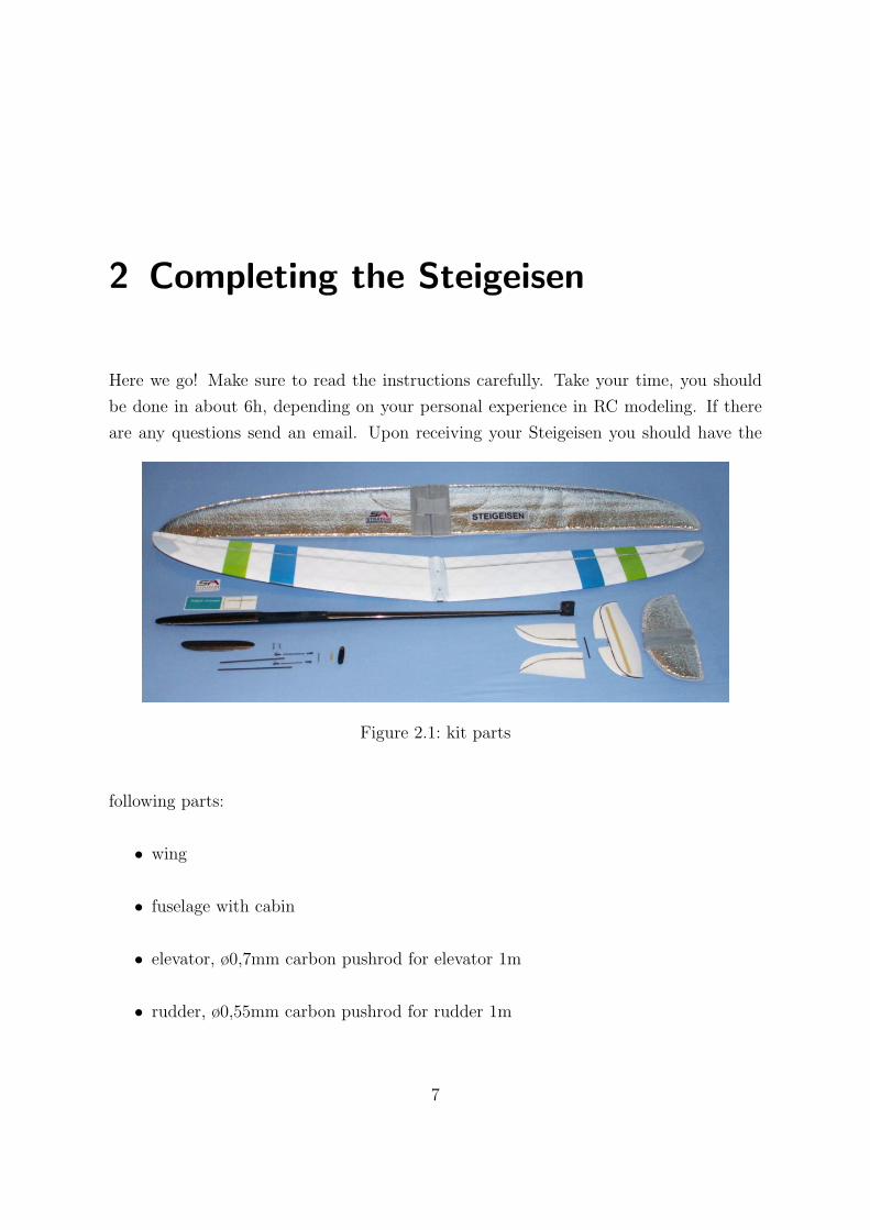
Here we go! Make sure to read the instructions carefully. Take your time, you should
be done in about 6h, depending on your personal experience in RC modeling. If there
are any questions send an email. Upon receiving your Steigeisen you should have the
Figure 2.1: kit parts
following parts:
• wing
• fuselage with cabin
• elevator, ø0,7mm carbon pushrod for elevator 1m
• rudder, ø0,55mm carbon pushrod for rudder 1m
7
• ø3/2mm carbon rod for flaperons (170mm & 150mm)
• ø2mm carbon rod 100mm (for connection ball pan to ø3/2mm carbon rod)
• bell crank for elevator with micro ball bearing ø2,5mm
• ø2,5mm carbon rod 65mm for elevator / ø1,5mm carbon rod for elevator 35mm
• sticker Logo-Team, sticker StratAir
• threaded bar (to be cut into two halves), M3 socked screw 2x
• 4x ball end, 4x ball pan
Additionally if ordered:
• wing & rudder protection covers
• throwing peg power
• ballast system (up to 85g!)
2.1 Wing
When handling the wing make sure that no sharp edged objects are around. I use an old
towel or bubble wrap on my work bench to protect the wing form scratches und dents.
An even better choice are the wing covers provided by Stratair.com
Making the levers:
Push the flaps down and use some 5min Epoxy with cotton to reinforce the area where
the steel rods enter the flap. Be careful not to get glue into the hinge. If this makes the
8
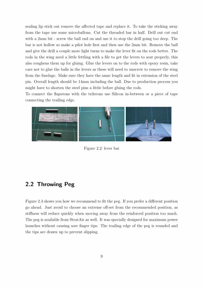
sealing lip stick out remove the affected tape and replace it. To take the sticking away
from the tape use some microballons. Cut the threaded bar in half. Drill out cut end
with a 2mm bit - screw the ball end on and use it to stop the drill going too deep. The
bar is not hollow so make a pilot hole first and then use the 2mm bit. Remove the ball
and give the drill a couple more light turns to make the lever fit on the rods better. The
rods in the wing need a little fettling with a file to get the levers to seat properly, this
also roughens them up for gluing. Glue the levers on to the rods with epoxy resin, take
care not to glue the balls in the levers as these will need to unscrew to remove the wing
from the fuselage. Make sure they have the same length and fit in extension of the steel
pin. Overall length should be 14mm including the ball. Due to production process you
might have to shorten the steel pins a little before gluing the rods.
To connect the flaperons with the trilerons use Silicon in-between or a piece of tape
connecting the trailing edge.
Figure 2.2: lever bar
2.2 Throwing Peg
Figure 2.3 shows you how we recommend to fit the peg. If you prefer a different position
go ahead. Just avoid to choose an extreme off-set from the recommended position, as
stiffness will reduce quickly when moving away from the reinforced position too much.
The peg is available from StratAir as well. It was specially designed for maximum power
launches without causing sore finger tips. The trailing edge of the peg is rounded and
the tips are drawn up to prevent slipping.
9
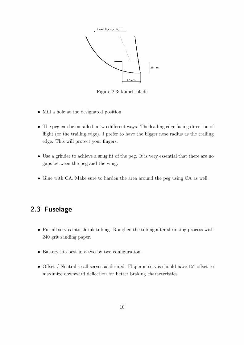
Figure 2.3: launch blade
• Mill a hole at the designated position.
• The peg can be installed in two different ways. The leading edge facing direction of
flight (or the trailing edge). I prefer to have the bigger nose radius as the trailing
edge. This will protect your fingers.
• Use a grinder to achieve a snug fit of the peg. It is very essential that there are no
gaps between the peg and the wing.
• Glue with CA. Make sure to harden the area around the peg using CA as well.
2.3 Fuselage
• Put all servos into shrink tubing. Roughen the tubing after shrinking process with
240 grit sanding paper.
• Battery fits best in a two by two configuration.
• Offset / Neutralise all servos as desired. Flaperon servos should have 15◦ offset to
maximize downward deflection for better braking characteristics
10
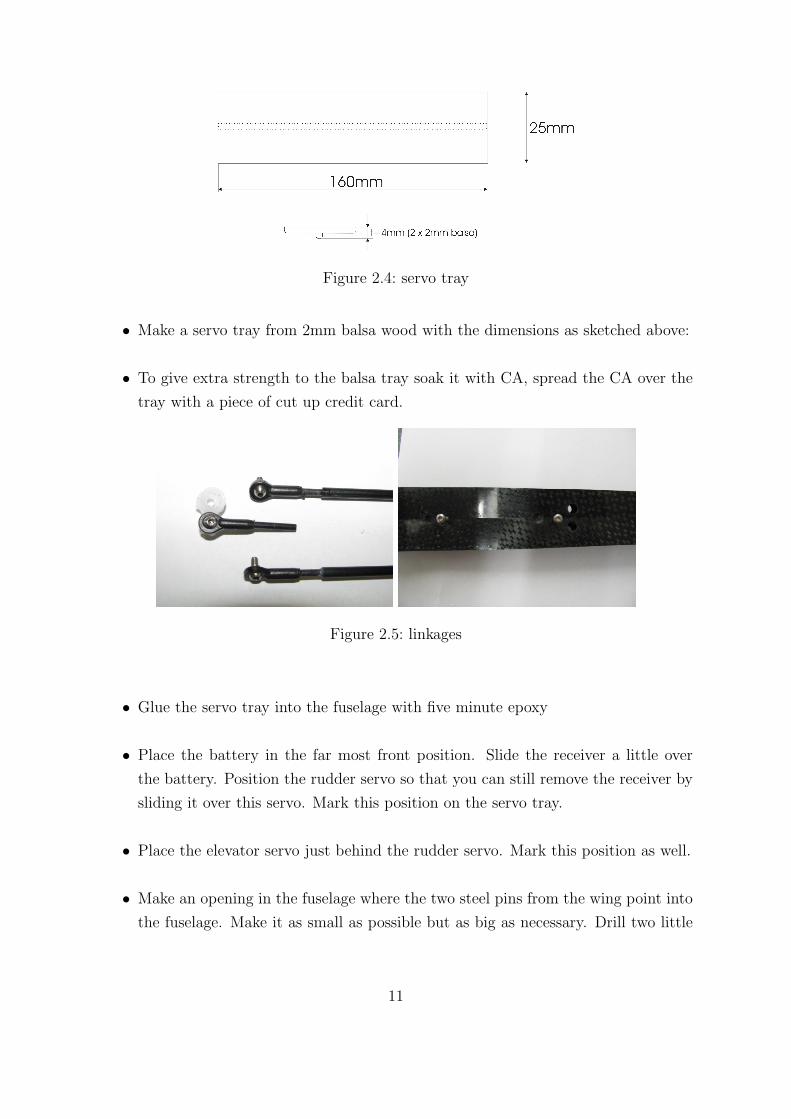
Figure 2.4: servo tray
• Make a servo tray from 2mm balsa wood with the dimensions as sketched above:
• To give extra strength to the balsa tray soak it with CA, spread the CA over the
tray with a piece of cut up credit card.
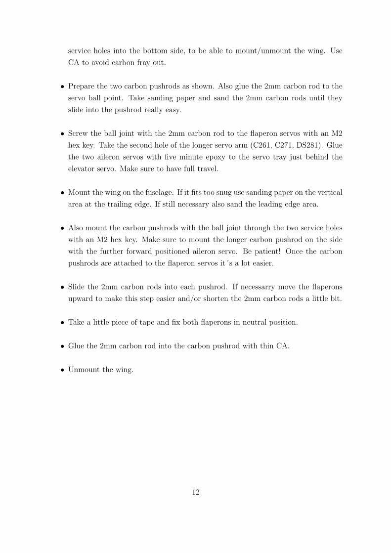
Figure 2.5: linkages
• Glue the servo tray into the fuselage with five minute epoxy
• Place the battery in the far most front position. Slide the receiver a little over
the battery. Position the rudder servo so that you can still remove the receiver by
sliding it over this servo. Mark this position on the servo tray.
• Place the elevator servo just behind the rudder servo. Mark this position as well.
• Make an opening in the fuselage where the two steel pins from the wing point into
the fuselage. Make it as small as possible but as big as necessary. Drill two little
11
service holes into the bottom side, to be able to mount/unmount the wing. Use
CA to avoid carbon fray out.
• Prepare the two carbon pushrods as shown. Also glue the 2mm carbon rod to the
servo ball point. Take sanding paper and sand the 2mm carbon rods until they
slide into the pushrod really easy.
• Screw the ball joint with the 2mm carbon rod to the flaperon servos with an M2
hex key. Take the second hole of the longer servo arm (C261, C271, DS281). Glue
the two aileron servos with five minute epoxy to the servo tray just behind the
elevator servo. Make sure to have full travel.
• Mount the wing on the fuselage. If it fits too snug use sanding paper on the vertical
area at the trailing edge. If still necessary also sand the leading edge area.
• Also mount the carbon pushrods with the ball joint through the two service holes
with an M2 hex key. Make sure to mount the longer carbon pushrod on the side
with the further forward positioned aileron servo. Be patient! Once the carbon
pushrods are attached to the flaperon servos it´s a lot easier.
• Slide the 2mm carbon rods into each pushrod. If necessarry move the flaperons
upward to make this step easier and/or shorten the 2mm carbon rods a little bit.
• Take a little piece of tape and fix both flaperons in neutral position.
• Glue the 2mm carbon rod into the carbon pushrod with thin CA.
• Unmount the wing.
12
2.4 RC-Components
2.5 Tailplanes
The next step before continuing with the rudder and elevator servo is the tail unit.
• The 2,5mm carbon will hold the split all flying stab. The carbon needs to be a
snug fit when pushed through the micro ball bearing. If necessary use 600-1200
grit sanding on the carbon rod. Be very careful not to take off too much! Just
enough so that the carbon has the described snug fit.
• The joints for the piano wire to carbon pushrod can’t be too long or the elevator
may end up with limited movement.
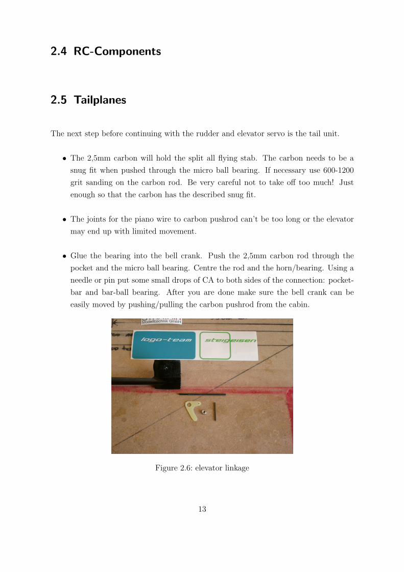
• Glue the bearing into the bell crank. Push the 2,5mm carbon rod through the
pocket and the micro ball bearing. Centre the rod and the horn/bearing. Using a
needle or pin put some small drops of CA to both sides of the connection: pocket-
bar and bar-ball bearing. After you are done make sure the bell crank can be
easily moved by pushing/pulling the carbon pushrod from the cabin.
Figure 2.6: elevator linkage
13
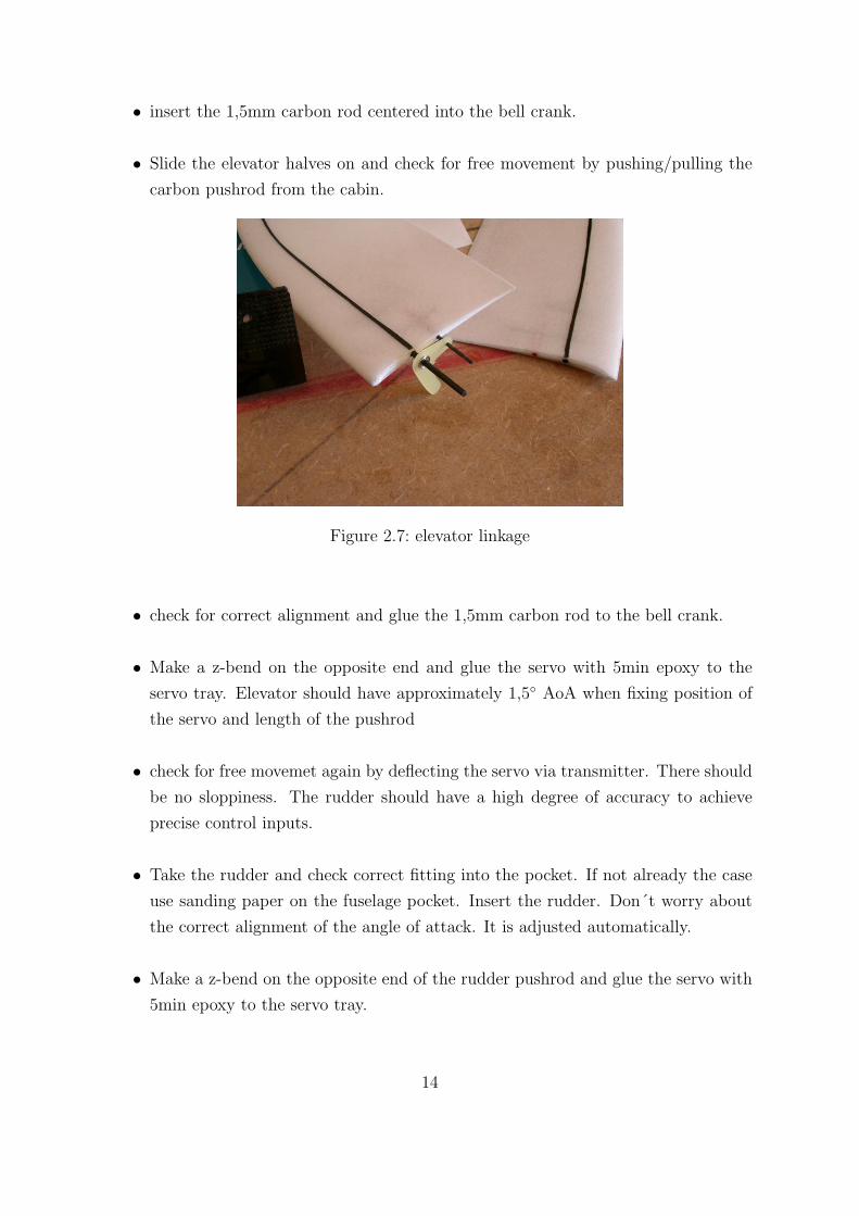
• insert the 1,5mm carbon rod centered into the bell crank.
• Slide the elevator halves on and check for free movement by pushing/pulling the
carbon pushrod from the cabin.
Figure 2.7: elevator linkage
• check for correct alignment and glue the 1,5mm carbon rod to the bell crank.
• Make a z-bend on the opposite end and glue the servo with 5min epoxy to the
servo tray. Elevator should have approximately 1,5◦ AoA when fixing position of
the servo and length of the pushrod
• check for free movemet again by deflecting the servo via transmitter. There should
be no sloppiness. The rudder should have a high degree of accuracy to achieve
precise control inputs.
• Take the rudder and check correct fitting into the pocket. If not already the case
use sanding paper on the fuselage pocket. Insert the rudder. Don´t worry about
the correct alignment of the angle of attack. It is adjusted automatically.
• Make a z-bend on the opposite end of the rudder pushrod and glue the servo with
5min epoxy to the servo tray.
14
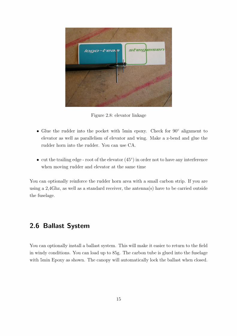
Figure 2.8: elevator linkage
• Glue the rudder into the pocket with 5min epoxy. Check for 90◦ alignment to
elevator as well as parallelism of elevator and wing. Make a z-bend and glue the
rudder horn into the rudder. You can use CA.
• cut the trailing edge - root of the elevator (45◦) in order not to have any interference
when moving rudder and elevator at the same time
You can optionally reinforce the rudder horn area with a small carbon strip. If you are
using a 2,4Ghz, as well as a standard receiver, the antenna(s) have to be carried outside
the fuselage.
2.6 Ballast System
You can optionally install a ballast system. This will make it easier to return to the field
in windy conditions. You can load up to 85g. The carbon tube is glued into the fuselage
with 5min Epoxy as shown. The canopy will automatically lock the ballast when closed.
15
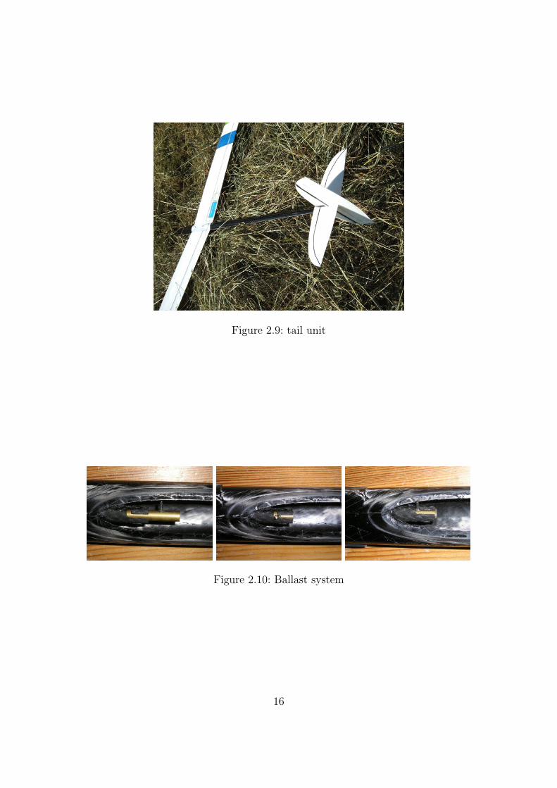
Figure 2.9: tail unit
Figure 2.10: Ballast system
16
3 Flying the Steigeisen
Congratulations! Now comes the fun part. We recommend to begin with the given
Center of Gravity and throws. As you become more familiar with your Steigeisen you
can change them to your personal comfort. Start off with a forward CG.
3.1 Center of Gravity
CG-Range for the Steigeisen is: 73 +/- 1mm from the leading edge. After the first
few flights the Steigeisen should also be balanced laterally. Start to tape little lead
pieces on the wing tip opposite to the throwing peg. Once you are satisfied take off
all the lead and put it on a scale. Drill a small hole in the wing and inject just as
much resin/microballons mixture as the weight of the lead. Be careful not to have resin
running into your flaperon hinge. Close the drilling hole with a piece of tape. You will
reinforce the tip while achieving a smooth surface with no bulky lead pieces sticking on
your wing. Peel off the tape after the resin has cured.
3.2 Throws
For best results in F3K Competition Flight as well as pure joy, it is essential to use
the whole potential of your Steigeisen. The Flying characteristics can be separated into
17
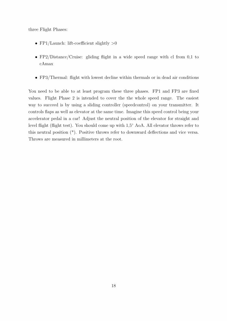
three Flight Phases:
• FP1/Launch: lift-coefficient slightly >0
• FP2/Distance/Cruise: gliding flight in a wide speed range with cl from 0,1 to
cAmax
• FP3/Thermal: flight with lowest decline within thermals or in dead air conditions
You need to be able to at least program these three phases. FP1 and FP3 are fixed
values. Flight Phase 2 is intended to cover the the whole speed range. The easiest
way to succeed is by using a sliding controller (speedcontrol) on your transmitter. It
controls flaps as well as elevator at the same time. Imagine this speed control being your
accelerator pedal in a car! Adjust the neutral position of the elevator for straight and
level flight (flight test). You should come up with 1,5◦ AoA. All elevator throws refer to
this neutral position (*). Positive throws refer to downward deflections and vice versa.
Throws are measured in millimeters at the root.
18
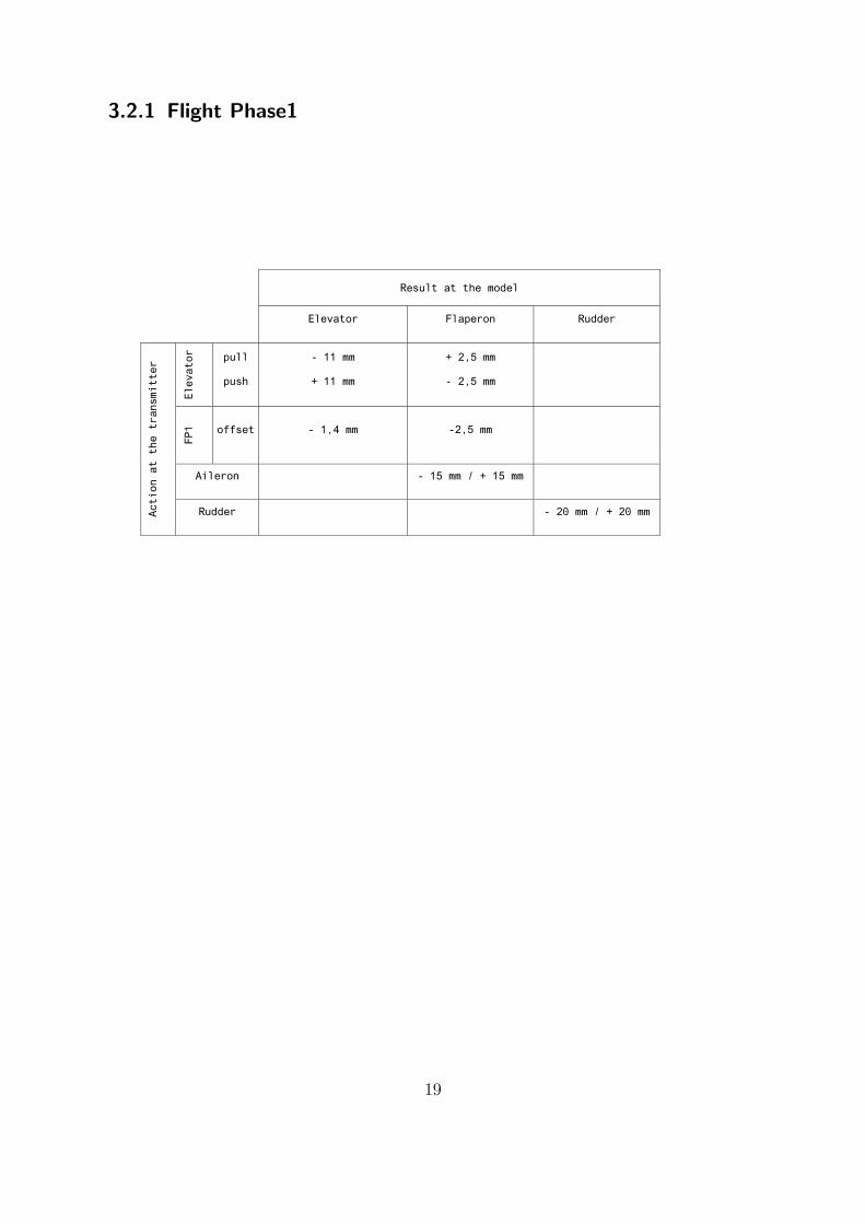
3.2.1 Flight Phase1
Result at the model
Elevator Flaperon Rudder
Elevator
pull
push
- 11 mm
+ 11 mm
+ 2,5 mm
- 2,5 mm
FP1
offset - 1,4 mm -2,5 mm
Aileron - 15 mm / + 15 mm
Action at the transmitter
Rudder - 20 mm / + 20 mm
19
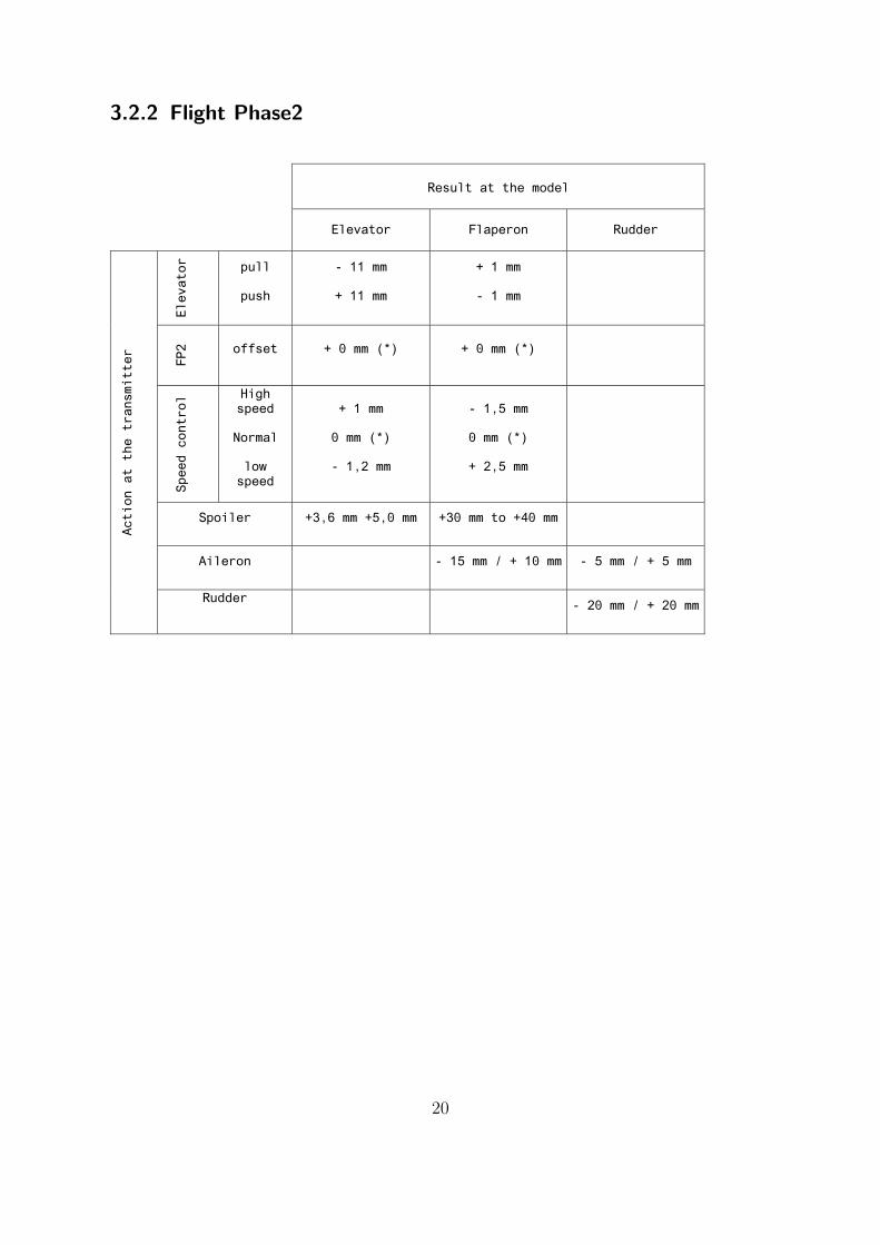
3.2.2 Flight Phase2
Result at the model
Elevator Flaperon Rudder
Elevator
pull
push
- 11 mm
+ 11 mm
+ 1 mm
- 1 mm
FP2
offset + 0 mm (*) + 0 mm (*)
Speed control High
speed
Normal
low speed
+ 1 mm
0 mm (*)
- 1,2 mm
- 1,5 mm
0 mm (*)
+ 2,5 mm
Spoiler +3,6 mm +5,0 mm +30 mm to +40 mm
Aileron - 15 mm / + 10 mm - 5 mm / + 5 mm
Action at the transmitter
Rudder - 20 mm / + 20 mm
20
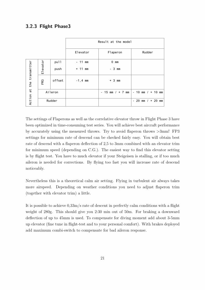
3.2.3 Flight Phase3
Result at the model
Elevator Flaperon Rudder
Elevator
pull
push
- 11 mm
+ 11 mm
0 mm
- 3 mm
FM3
offset -1,4 mm + 3 mm
Aileron - 15 mm / + 7 mm - 10 mm / + 10 mm
Action at the transmitter
Rudder - 20 mm / + 20 mm
The settings of Flaperons as well as the correlative elevator throw in Flight Phase 3 have
been optimized in time-consuming test series. You will achieve best aircraft performance
by accurately using the measured throws. Try to avoid flaperon throws >3mm! FP3
settings for minimum rate of descend can be checked fairly easy. You will obtain best
rate of descend with a flaperon deflection of 2,5 to 3mm combined with an elevator trim
for minimum speed (depending on C.G.). The easiest way to find this elevator setting
is by flight test. You have to much elevator if your Steigeisen is stalling, or if too much
aileron is needed for corrections. By flying too fast you will increase rate of descend
noticeably.
Nevertheless this is a theoretical calm air setting. Flying in turbulent air always takes
more airspeed. Depending on weather conditions you need to adjust flaperon trim
(together with elevator trim) a little.
It is possible to achieve 0,33m/s rate of descent in perfectly calm conditions with a flight
weight of 280g. This should give you 2:30 min out of 50m. For braking a downward
deflection of up to 45mm is used. To compensate for diving moment add about 3-5mm
up elevator (fine tune in flight-test and to your personal comfort). With brakes deployed
add maximum combi-switch to compensate for bad aileron response.
21
3.3 First Flight
Check your glider carefully before launching for the first time. Make a normal javelin
launch, glide path should be straight and level. Correct all trims before launching via
DLG technique for the first time. Don´t forget to switch to launch mode (which you
have checked prior, too)! One word needs to be said about accumulator running time.
Depending on how many Digital Servos you are using safe flying time is reduced to
30-45min with a 350mAh battery. So don´t forget to charge in time.
3.4 Maintenance
For long lasting life of your Steigeisen you should always handle it with care. Even
though every single fuselage is tested don´t stress the structure by locally applied forces
(pressing with your thumb e.g.). The Steigeisen fuselage will withstand your launches,
don´t worry. Use the wing bags/covers when not flying. They have a heat reflecting
surface and will also protect your wing from dents. Most damages occur not while flying,
but in your workshop or on the way to your car. Store your glider in a dry and cool
place. Hot cars are not appropriate. We would love to hear about your experiences with
the Steigeisen. Send us your pictures as well as your suggestions for improvement. We
will try to translate them into action. What comes next? We are working on a new
RDS technology, Kevlar wings, an Electric Version and Prepreg Technology.
Florian Seibel, Michael Wohlfahrt
22


