Seite 1 von 16 WAE-1, WAE-2, WAE-3, WAE-4, WAB-1 Betriebsanleitung Hydraulikaggregat 1 - 8 9 - 16 WAE-1 Hydraulikaggregat 230 V mit 4/3 Handschiebeventil WAE-2 Hydraulikaggregat 230 V mit 4/3 elekt. Wegesitzventil WAE-3 Hydraulikaggregat 400 V mit 4/3 Handschiebeventil WAE-4 Hydraulikaggregat 400 V mit 4/3 elekt. Wegesitzventil WAB-1 Hydraulikaggregat Benzin mit 4/3 Handschiebeventil Ausgabe 05.08
Transcript
Seite 1 von 16 WAE-1, WAE-2, WAE-3, WAE-4, WAB-1
Betriebsanleitung Hydraulikaggregat
1 - 8 9 - 16
WAE-1 � Hydraulikaggregat 230 V mit 4/3 Handschiebeventil
WAE-2 � Hydraulikaggregat 230 V mit 4/3 elekt. Wegesitzventil
WAE-3 � Hydraulikaggregat 400 V mit 4/3 Handschiebeventil
WAE-4 � Hydraulikaggregat 400 V mit 4/3 elekt. Wegesitzventil
WAB-1 � Hydraulikaggregat Benzin mit 4/3 Handschiebeventil
Ausgabe 05.08
Seite 2 von 16 WAE-1, WAE-2, WAE-3, WAE-4, WAB-1
Vor der Inbetriebnahme der Hydraulik - Aggregate müssen diese Betriebsanleitung und die Sicherheitshinweise sorgfältig gelesen werden! 1 Bestimmungsgemäße Verwendung des Gerätes 1.1 Das Gerät ist nach dem Stand der Technik und den anerkannten sicherheitstechnischen Regeln gebaut. Dennoch können bei seiner Verwendung Gefahren für Leib und Leben des Benutzers oder Dritter bzw. Beeinträchtigungen des Gerätes und anderer Sachwerte entstehen. 1.2 Gerät nur in technisch einwandfreiem Zustand sowie bestimmungsgemäß, sicherheits- und gefahrenbewusst, unter Beachtung der Betriebsanleitung, benutzen! Insbesondere Störungen, die die Sicherheit beeinträchtigen können, umgehend beseitigen (lassen)! 1.3 Das Gerät ist ausschließlich zum in der Betriebsanleitung dargestellten Zweck bestimmt. Eine andere oder darüber hinausgehende Benutzung gilt als nicht bestimmungsgemäß. Für hieraus resultierende Schäden haftet der Hersteller/Lieferer nicht. Das Risiko trägt allein der Anwender. Zur bestimmungsgemäßen Verwendung gehört auch das Beachten der Betriebsanleitung und die Einhaltung der Inspektions- und Wartungsbedingungen.
2 Organisatorische Maßnahmen 2.1 Die Betriebsanleitung ständig am Einsatzort des Gerätes griffbereit aufbewahren! 2.2 Ergänzend zur Betriebsanleitung allgemeingültige gesetzliche und sonstige verbindliche Regelungen zur Unfallverhütung und zum Umweltschutz beachten und anweisen! Dazu zählen insbesondere das Tragen von Dienst- oder Schutzkleidung, Schutzhelm mit Visier oder Schutzbrille und Schutzhandschuhe. 2.3 Das Gerät darf nur von einer einschlägig geschulten, sicherheitstechnisch ausgebildeten Person bedient werden, da sonst Verletzungsgefahr droht. 2.4 Alle Sicherheits- und Gefahrenhinweise an dem Gerät beachten! Alle Sicherheits- und Gefahrenhinweise an/auf dem Gerät vollzählig in lesbarem Zustand halten! 2.5 Keine Veränderungen, An- und Umbauten an dem Gerät, die die Sicherheit beeinträchtigen könnten, ohne Genehmigung des Lieferers vornehmen! Dies gilt auch für den Einbau und die Einstellung von Sicherheitseinrichtungen und Ventilen. 2.6 Ersatzteile müssen den vom Hersteller festgelegten technischen Anforderungen entsprechen. Dies ist bei Originalersatzteilen immer gewährleistet. 2.7 Hydraulik-Schlauchleitungen in den angegebenen bzw. in angemessenen Zeitabständen auswechseln, auch wenn keine sicherheitsrelevanten Mängel erkennbar sind! Dies muss jedoch spätestens nach 10 Jahren erfolgen! 2.8 Vorgeschriebene oder in der Betriebsanleitung angegebene Fristen für wiederkehrende Prüfungen/Inspektionen einhalten! 2.9 Ordnungsgemäße Entsorgung aller Verpackungsmaterialien und abgebauter Teile sicherstellen!
3 Allgemeine Sicherheitshinweise 3.1 Bei Funktionsstörungen Gerät sofort stillsetzen und sichern! Störungen umgehend beseitigen (lassen)! 3.2 Vor Einschalten / Ingangsetzen und während des Betriebes des Gerätes sicherstellen, dass niemand durch das anlaufende Gerät gefährdet werden kann! 3.3 Vor dem Transport des Gerätes stets die unfallsichere Unterbringung des Zubehörs kontrollieren! 3.4 Beim Arbeiten für ausreichende Beleuchtung sorgen! 3.5 Jede Arbeitsweise unterlassen, die die Sicherheit und oder Standsicherheit des Gerätes beeinträchtigt! 3.6 Nach jedem Einsatz Gerät auf äußerlich erkennbare Schäden und Mängel prüfen! Eingetretene Veränderungen (einschl. der des Betriebsverhaltens) sofort der zuständigen Stelle melden! Gerät ggf. sofort stillsetzen und sichern! Alle Leitungen, Schläuche und Verschraubungen auf Undichtigkeiten und äußerlich erkennbare Beschädigungen überprüfen und umgehend beseitigen! Herausspritzendes Öl kann zu Verletzungen und Bränden führen.
Seite 3 von 16 WAE-1, WAE-2, WAE-3, WAE-4, WAB-1
3.7 Alle Sicherheitseinrichtungen auf Vollständigkeit und einwandfreien Zustand überprüfen: - Hinweis- und Kennzeichnungsschilder (Gefahrenhinweise) - Sicherheitsabdeckungen (z. B. Motor-Schutzdächer, Hitzeschilder usw.) auf Vorhanden sein und einwandfreien Zustand überprüfen. 3.8 Das Arbeiten unter Lasten ist verboten, wenn diese ausschließlich mit hydraulischen Zylindern angehoben sind. Ist diese Arbeit unerlässlich, so sind ausreichende mechanische Abstützungen zusätzlich erforderlich. 3.9 Schlauchleitungen nicht mechanisch beanspruchen (Ziehen, Knicken usw.) 3.10 Beim Arbeiten in der Nähe von spannungsführenden Bauteilen und Leitungen sind geeignete Vorkehrungen zur
Vermeidung von Stromübergängen oder Hochspannungsüberschlägen auf die Handpumpe und daran angeschlossener Geräte zu treffen.
3.11 Der Entstehung elektrostatischer Aufladungen mit möglicher Folge von Funkenbildung im Umgang mit dem Gerät ist vorzubeugen. 3.12 Bei der Aufstellung des Gerätes ist Sorge dafür zu tragen, dass Funktion und Sicherheit des Gerätes nicht durch starke externe Temperatureinwirkungen beeinträchtigt werden.
4 Wartungs- und Instandhaltungshinweise 4.1 Zur Durchführung von Wartungs- und Instandsetzungsmaßnahmen ist eine der Arbeit angemessene Werkstattausrüstung unbedingt erforderlich. An dem Gerät darf nur Personal mit speziellen Kenntnissen und Erfahrungen in der Hydraulik arbeiten! 4.2 Gerät und insbesondere Anschlüsse und Verschraubungen zu Beginn der Arbeiten von Öl und allen Verschmutzungen reinigen. Keine aggressiven Reinigungsmittel verwenden. Faserfreie Putztücher benutzen und auf peinliche Sauberkeit v. a. beim Wiederzusammenbau achten! 4.3 Beim Zerlegen von Geräten ist Sorge zu tragen, dass auslaufende Hydraulikflüssigkeit restlos aufgefangen wird, nicht in das Erdreich gelangt und gemäß bestehender Vorschriften entsorgt wird! 4.4 Gelöste Schrauben- und Gewindeverbindungen bei Montage stets fest anziehen und vorgeschriebene Drehmomente beachten! 4.5 Aggressive Medien (Säuren, Lauge, Lösemittel, Dämpfe) können das Gerät beschädigen. Muss das Gerät in Ausnahmefällen in einer solchen Umgebung betrieben werden oder kommt es damit in Berührung, so ist eine gründliche Reinigung des gesamten Gerätes vorzunehmen. Außerdem ist dann eine Prüfung nach Punkt 3.6 vorzunehmen. 4.6 Arbeiten an elektrischen Geräten dürfen nur von einer Elektrofachkraft oder von unterwiesenen Personen unter Leitung und Aufsicht einer Elektrofachkraft den elektrotechnischen Regeln entsprechend vorgenommen werden. 4.7 Die elektrische Ausrüstung eines Gerätes ist regelmäßig zu inspizieren / prüfen. Mängel, wie lose Verbindungen bzw. angeschmorte Kabel, müssen sofort beseitigt werde.
5 Sicherheitsregeln für Hydraulik-Schlauchleitungen Alle sicherheitsrelevanten Informationen über den Einsatz von Schlauchleitungen finden Sie in der Anleitung (wird mit den Schläuchen mitgeliefert).
6 Verwendung 6.1 Allgemeine Hinweise Die Hydraulik - Aggregate (mit den Anschlüssen P und T in G3/8“) dient zum Betrieb von doppelwirkenden Werkzeug-hydraulik - Zylindern bzw. Rettungsgeräten. Ein Einsatz in mit Geräten anderer Hersteller ist möglich, bedarf aber der technischen Prüfung und Zustimmung von der Fa. Werner Weitner GmbH in jedem Einzelfall.
Achtung! Stets die Produktbeschränkungen bezüglich Betriebsdruck, Belastungsgrenzwerten und Einsatzbedingungen beachten. Der Betriebsdruck darf nicht höher sein als der niedrigste max. Betriebsdruck aller Systemkomponenten. Am Druckbegrenzungsventil darf NIEMALS ein höherer als der in Punkt 11 angegebene maximale Betriebsdruck der Aggregate eingestellt werden. Eine höhere Einstellung kann zu Sachschäden und/oder Verletzungen führen. Es ist darauf zu achten, dass die Nutzmenge der Aggregate (s. Punkt 18) zum Betreiben der angeschlossenen Zylinder bzw. Geräte ausreicht. Die erforderliche Betriebsölmenge ist den technischen Daten bzw. der Betriebsanleitung der jeweiligen Zylinder bzw. Geräte zu entnehmen.
Seite 4 von 16 WAE-1, WAE-2, WAE-3, WAE-4, WAB-1
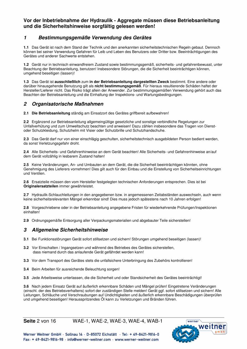
7 Installation Alle Gewinde 1 ½ - mal mit Teflon - Band (oder einer geeigneten Gewindedichtung) umwickeln, dabei den ersten kompletten Gewindegang freilassen, um zu vermeiden, dass Teile des Bands in das Hydrauliksystem gelangen, und Schaden verursachen. Lose Enden abschneiden. VORSICHT: Um ordnungsgemäßen Betrieb zu gewährleisten, darauf achten, dass Schläuche nicht geknickt oder stark gebogen werden. Wenn ein Schlauch Knicke oder sonstige Schäden aufweist, muss er ausgetauscht werden. Ein beschädigter Schlauch kann bei hohem Druck reißen und Verletzungen verursachen. Eine Kupplungshälfte des Schlauchs mit der Kupplungshälfte des Zylinderausfahranschlusses (A) verbinden, die andere Hälfte an das Wegeventil (B) des Hydraulikaggregats anschließen. Den Kupplungsbund von Hand fest anziehen. Zum Festziehen der beiden Kupplungshälften KEINE Werkzeuge verwenden. Nachfüllen von Öl Zur Prüfung des Ölstands den Messstab der Entlüftungs- / Einfüllöffnung (F) abschrauben. Hydrauliköl nachfüllen, bis der Ölspiegel an der obersten Markierung des Messstabes liegt. Wichtig: Nur dann Öl nachfüllen, wenn alle Systemkomponenten vollständig eingefahren sind, da sich sonst im System mehr Öl befindet, als der Tank aufnehmen kann.
8 Betrieb Hinweis: Um keinen Leistungsverlust zwischen der elektrischen Steckdose und dem Pumpenmotor einzubüßen, ein möglichst kurzes Verlängerungskabel verwenden. Der Pumpenmotor funktioniert bei niedriger Spannung, jedoch sind die Motordrehzahl und Ölfördermenge geringer.
1. Alle Systemverbindungen und –anschlüsse auf festen und leckfreien Sitz überprüfen.
2. Den Flüssigkeitsstand überprüfen und ggf. Flüssigkeit nachfüllen. 3. Den Pumpenentlüftungsdeckel (F) in der vorderen, rechten Ecke
des Tanks mit ein bis zwei vollständigen Umdrehungen öffnen. VORSICHT: Wenn die Pumpe läuft, muss die Entlüftungsöffnung
offen sein.
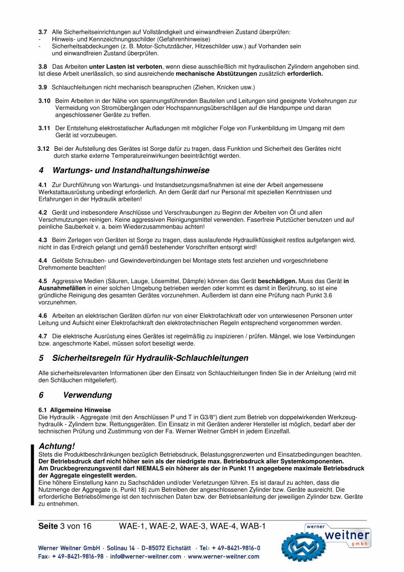
9 Handschiebeventil Das Hydraulik - Aggregat verfügt über ein 4/3 Wegeventil mit jeweils drei Positionen zum Einsatz von doppelwirkenden Zylindern, deren Aus- und Einfahrbewegung hydraulisch aktiviert wird. Das 4/3 Wegeventil steuert die Zufuhr, bzw. den Rücklauf der hydraulischen Flüssigkeit zu, bzw. von den Hydrauliksystemkomponenten. Zum Ausfahren des Zylinders das Ventil auf die Ausfahrposition (A) stellen. Der Zylinder fährt so lange aus, bis das Ventil auf Position (O) gestellt wird. Zum einfahren des Zylinders das Ventil auf die Einfahrstellung (B) stellen. Die Ventilstellungen sind in der Abbildung
dargestellt: ���� B – Einfahren O – Leerlauf A – Ausfahren
Seite 5 von 16 WAE-1, WAE-2, WAE-3, WAE-4, WAB-1
10 elekt. Wegesitzventil Die Hydraulik - Aggregate WAE-2 und WAE-4verfügen über ein 4/3 elektr. Wegesitzventil mit jeweils drei Positionen zum Einsatz von doppelwirkenden Zylindern, deren Aus- und Einfahrbewegung hydraulisch aktiviert wird. Das 4/3 Wegeventil steuert die Zufuhr, bzw. den Rücklauf der hydraulischen Flüssigkeit zu, bzw. von den Hydrauliksystemkomponenten. Zum Ausfahren des Zylinders das Ventil auf die Ausfahrposition (A) stellen (Druckknopf „Auf“ an der Fernsteuerung be-tätigen). Der Zylinder fährt so lange aus, bis das Ventil auf Position (O) (alle Druckknöpfe unbetätigt) gestellt wird. Zum einfahren des Zylinders das Ventil auf die Einfahrstellung (B) stellen (Druckknopf „Ab“ an der Fernsteuerung betätigen). Die Ventilstellungen sind in der Abbildung
dargestellt: ���� B – Einfahren O – Leerlauf A – Ausfahren 11 Erstinbetriebnahme und Entlüftung: Erstinbetriebnahme: Bei der Erstinbetriebnahme ist der Ölbehälter des Aggregates mit Hydrauliköl (siehe Öl-empfehlung) zu füllen. Um Ansaugschwierigkeiten zu vermeiden, muss dabei die Hydraulikpumpe entlüftet werden:
1. Öleinfülldeckel / Messstab am Ölbehälter ganz herausschrauben und langsam Hydrauliköl einfüllen (Ölstand mit Messstab / Markierung überprüfen!).
2. Um die Luft möglichst restlos zu entfernen, Motor nicht direkt starten, sondern: Benzinmotor: Kerzenstecker von der Zündkerze abziehen, Motor mit Startseil mehrmals langsam durchdrehen, danach Kerzenstecker aufstecken. Elektromotor: Mehrmals hintereinander ein- und ausschalten, dass der Motor langsam dreht. Vor dem Wiedereinschalten muss der Motor zum Stillstand kommen.
3. Einfüllschraube zudrehen und wieder leicht zur Entlüftung während des Betriebes öffnen. Entlüftung: Beim ersten Anschließen des Hydrauliksystems wird Luft in den Komponenten eingeschlossen. Um einen reibungslosen, sicheren Betrieb zu gewährleisten, muss das System entlüftet werden. Hierzu mehrere Betriebszyklen ohne Belastung der Zylinder durchlaufen. Wenn die Zylinder reibungslos aus- und einfahren, ist das System entlüftet. VORSICHT: Um Verletzungen und Geräteschaden zu vermeiden, dürfen Zylinder nach Erreichen des maximalen Verfahrwegs bzw. des maximalen Betriebsdrucks nicht weiter unter Druck gesetzt werden. WARNUNG: Um Geräteschaden und Verletzungen zu vermeiden, darf der maximale Betriebsdruck von 700 bar nicht überschritten werden.
12 Bedienung Aufstellen Warnhinweis! Wegen möglicher Funkenbildung dürfen Hydraulik – Aggregate nicht in explosionsgefährdeter Umgebung eingesetzt werden. In geschlossenen Räumen keine Hydraulik – Aggregat mit Brennkraftmotor einsetzen! Beim Nach-füllen von Kraftstoff kein Benzin vergießen! Bei betriebswarmen Motor Nachfüllen vermeiden! Falls dies unbedingt er-forderlich ist, äußerste Sorgfalt walten lassen, da Explosionsgefahr besteht! Löschmittel bereithalten! Aggregat: Das Aggregat wird an geeigneter Stelle (sicherer Standort / ebene Fläche / genügend Abstand von Lasten und Fahrzeugen) aufstellen. Motor starten: Verbrennungsmotor, siehe separate Betriebsanleitung. Elektromotor, Aggregat an Stromversorgung anschließen, Ein / Aus – Schalter betätigen.
A - Ausfahren B - Einfahren
Seite 6 von 16 WAE-1, WAE-2, WAE-3, WAE-4, WAB-1
13 Instandhaltung / Wartung Aggregat Nach jedem Einsatz ist eine Sichtprüfung durchzuführen mindestens jedoch einmal jährlich. Alle 3 Jahre oder wenn Zweifel an der Sicherheit oder Zuverlässigkeit bestehen ist zusätzlich eine Funktionsprüfung durchzuführen. (Bei Ver-schmutzung vorher reinigen). Hydraulische Verbindungen auf festen Sitzen, bei Bedarf nachziehen. Aggregat, Steuer-ventil und Geräten an den mechanischen Teilen, sowie die Ventile und Schlauchleitungen auf Beschädigungen prüfen, ggf. erneuern. Schilder – Warnhinweise, Betätigungssymbole und Schutzabdeckungen (z.B. Schutzdach, Auspuffab-deckung) vorhanden und in Ordnung sind. Überprüfung des Ölstands Den Ölstand des Hydrauliköltanks nach jeweils 40 Betriebsstunden prüfen. Falls erforderlich, Öl bis zur obersten Markierung des Ölmessstabes nachfüllen. Nur die in Tabelle 17.0 vorgeschriebenen Hydrauliköle verwenden. Die Verwendung anderer Öle oder Flüssigkeiten kann das System beschädigen, und die Garantieansprüche ungültig machen. Ölwechsel Das gesamte Öl nach jeweils 100 Betriebsstunden ablassen. Mit neuem Hydrauliköl nachfüllen. Wenn die Pumpe in einer sehr staubigen Umgebung oder bei hohen Temperaturen betrieben wird, muss das Öl häufiger abgelassen und ausgetauscht werden.
1. Um den Tank zu entleeren, die Ölablassschraube (A) unten links am Tank abschrauben.
2. Die Pumpe kippen, bis das gesamte Altöl abgelaufen ist, und wieder mit der Ablassschraube (A) verschließen.
3. Frisches Öl durch die Einfüllöffnung am Tankdeckel vorn rechts nachfüllen. Ölstand mit Ölmessstab kontrollieren (Die Füllmenge des Tanks beträgt 12 Liter).
4. Den Einfüllstöpsel (F) wieder aufschrauben. Reinigen des Tanks Der Pumpentank kann zur Reinigung herausgenommen werden. Wenn die Pumpe ständig in einer extrem staubigen Umgebung verwendet wird, sollte der Tank einmal pro Jahr gereinigt werden.
1. Das Öl gemäß Schritt 1 und 2 unter „Ölwechsel“ aus dem Tank ablassen. 2. Die 12 Schrauben lösen, mit denen die Pumpe am Tank befestigt ist. Die Pumpe vom Tank wegheben und die
Dichtung abnehmen. 3. Den Tank gründlich mit einem geeigneten Reinigungsmittel reinigen. 4. Die Pumpe und den Tank mit neuer Tankdichtung wieder zusammenbauen.
Hydraulische Dichtheit Gerät auf Ölverlust kontrollieren und defekte Dichtungen ggf. erneuern.
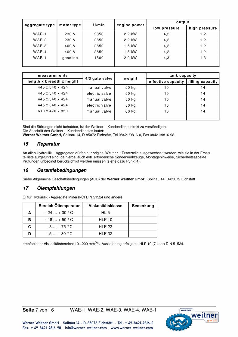
14 Störungen / Störungsbeseitigung Die Stromversorgungseinheit darf nur von einem qualifizierten Hydrauliktechniker repariert werden. Die folgenden Informationen sollen als Hilfe bei der Fehlerfeststellung dienen. Für Reparaturarbeiten wenden Sie sich an die Fa. Werner Weitner.
N i e d e r d r u c k H o c h d r u c k
W A E - 1 2 3 0 V 2 8 5 0 2 , 2 k W 4 , 1 1 , 2
W A E - 2 2 3 0 V 2 8 5 0 2 , 2 k W 4 , 1 1 , 2
W A E - 3 4 0 0 V 2 8 5 0 1 , 5 k W 4 , 1 1 , 2
W A E - 4 4 0 0 V 2 8 5 0 1 , 5 k W 4 , 1 1 , 2
W A B - 1 B e n z i n 1 5 0 0 2 , 0 k W 4 , 3 1 , 3
N u t z m e n g e F ü l l m e n g e
H a n d v e n t i l 5 0 k g 1 0 1 4
E l e k t r o v e n t i l 5 0 k g 1 0 1 4
H a n d v e n t i l 5 0 k g 1 0 1 4
E l e k t r o v e n t i l 5 0 k g 1 0 1 4
H a n d v e n t i l 6 0 k g 1 0 1 4
T a n k v o l u m e n
F ö r d e r l e i s t u n gA g g r e g a t t y p M o t o r t y p U / m i n L e i s t u n g
A b m e s s u n g e n4 / 3 W e g e v e n t i l G e w i c h t
L ä n g e x B r e i t e x H ö h e
4 4 5 x 3 4 0 x 4 2 4
4 4 5 x 3 4 0 x 4 2 4
6 1 0 x 4 7 0 x 8 5 0
4 4 5 x 3 4 0 x 4 2 4
4 4 5 x 3 4 0 x 4 2 4
Seite 7 von 16 WAE-1, WAE-2, WAE-3, WAE-4, WAB-1
Sind die Störungen nicht behebbar, ist der Weitner – Kundendienst direkt zu verständigen. Die Anschrift des Weitner – Kundendienstes lautet: Werner Weitner GmbH, Sollnau 14, D-85072 Eichstätt, Tel 08421/9816-0, Fax 08421/9816-98.
15 Reparatur An allen Hydraulik – Aggregaten dürfen nur original Weitner – Ersatzteile ausgewechselt werden, wie sie in der Ersatz-teilliste aufgeführt sind, da hierbei auch evtl. erforderliche Sonderwerkzeuge, Montagehinweise, Sicherheitsaspekte, Prüfungen unbedingt berücksichtigt werden müssen (siehe dazu Punkt 4).
16 Garantiebedingungen Siehe Allgemeine Geschäftsbedingungen (AGB) der Werner Weitner GmbH, Sollnau 14, D-85072 Eichstätt
17 Ölempfehlungen Öl für Hydraulik - Aggregate Mineral-Öl DIN 51524 und andere
empfohlener Viskositätsbereich: 10...200 mm2/s, Auslieferung erfolgt mit HLP 10 (7 Liter) DIN 51524.
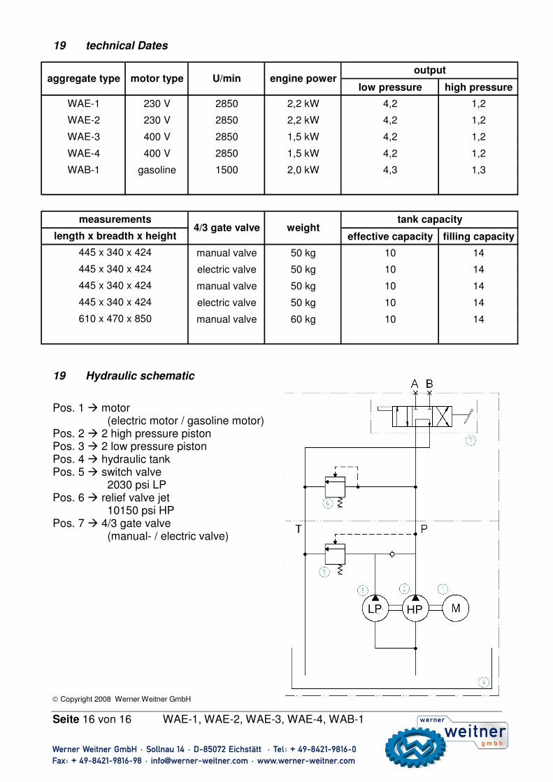
low pressure high pressure
W AE-1 230 V 2850 2,2 kW 4,2 1,2
W AE-2 230 V 2850 2,2 kW 4,2 1,2
W AE-3 400 V 2850 1,5 kW 4,2 1,2
W AE-4 400 V 2850 1,5 kW 4,2 1,2
W AB-1 gasoline 1500 2,0 kW 4,3 1,3
effective capacity filling capacity
m anual valve 50 kg 10 14
electric valve 50 kg 10 14
m anual valve 50 kg 10 14
electric valve 50 kg 10 14
m anual valve 60 kg 10 14
tank capacity
outputaggregate type motor type U/m in engine pow er
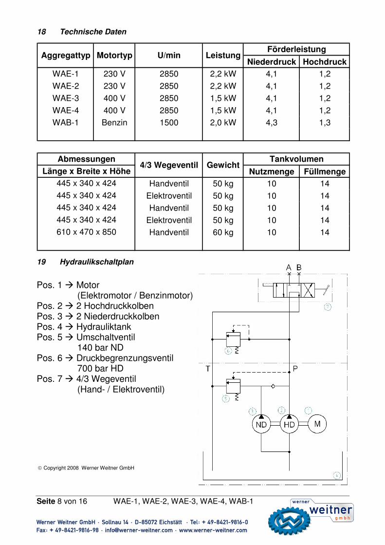
(Hand- / Elektroventil) Copyright 2008 Werner Weitner GmbH
Niederdruck Hochdruck
WAE-1 230 V 2850 2,2 kW 4,1 1,2
WAE-2 230 V 2850 2,2 kW 4,1 1,2
WAE-3 400 V 2850 1,5 kW 4,1 1,2
WAE-4 400 V 2850 1,5 kW 4,1 1,2
WAB-1 Benzin 1500 2,0 kW 4,3 1,3
Nutzmenge Füllmenge
Handventil 50 kg 10 14
Elektroventil 50 kg 10 14
Handventil 50 kg 10 14
Elektroventil 50 kg 10 14
Handventil 60 kg 10 14
Tankvolumen
FörderleistungAggregattyp Motortyp U/min Leistung
Abmessungen4/3 Wegeventil Gewicht
Länge x Breite x Höhe
445 x 340 x 424
445 x 340 x 424
610 x 470 x 850
445 x 340 x 424
445 x 340 x 424
Seite 9 von 16 WAE-1, WAE-2, WAE-3, WAE-4, WAB-1
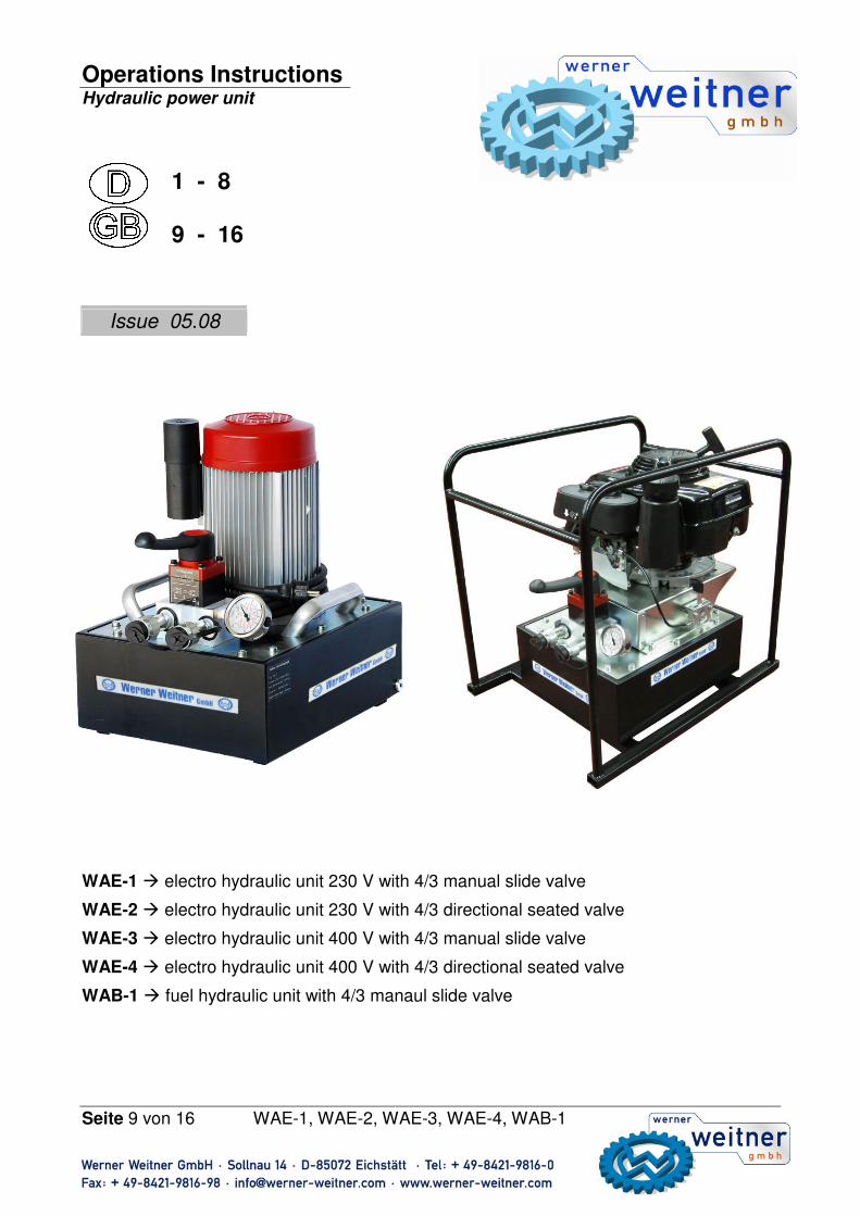
Operations Instructions Hydraulic power unit
1 - 8 9 - 16
WAE-1 � electro hydraulic unit 230 V with 4/3 manual slide valve
WAE-2 � electro hydraulic unit 230 V with 4/3 directional seated valve
WAE-3 � electro hydraulic unit 400 V with 4/3 manual slide valve
WAE-4 � electro hydraulic unit 400 V with 4/3 directional seated valve
WAB-1 � fuel hydraulic unit with 4/3 manaul slide valve
Issue 05.08
Seite 10 von 16 WAE-1, WAE-2, WAE-3, WAE-4, WAB-1
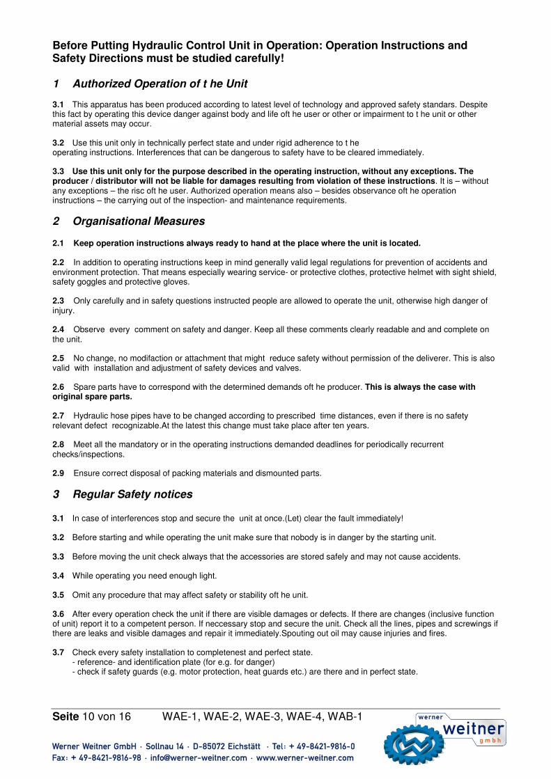
Before Putting Hydraulic Control Unit in Operation: Operation Instructions and Safety Directions must be studied carefully! 1 Authorized Operation of t he Unit 3.1 This apparatus has been produced according to latest level of technology and approved safety standars. Despite this fact by operating this device danger against body and life oft he user or other or impairment to t he unit or other material assets may occur. 3.2 Use this unit only in technically perfect state and under rigid adherence to t he operating instructions. Interferences that can be dangerous to safety have to be cleared immediately. 3.3 Use this unit only for the purpose described in the operating instruction, without any exceptions. The producer / distributor will not be liable for damages resulting from violation of these instructions. It is – without any exceptions – the risc oft he user. Authorized operation means also – besides observance oft he operation instructions – the carrying out of the inspection- and maintenance requirements.
2 Organisational Measures
2.1 Keep operation instructions always ready to hand at the place where the unit is located. 2.2 In addition to operating instructions keep in mind generally valid legal regulations for prevention of accidents and environment protection. That means especially wearing service- or protective clothes, protective helmet with sight shield, safety goggles and protective gloves. 2.3 Only carefully and in safety questions instructed people are allowed to operate the unit, otherwise high danger of injury. 2.4 Observe every comment on safety and danger. Keep all these comments clearly readable and and complete on the unit. 2.5 No change, no modifaction or attachment that might reduce safety without permission of the deliverer. This is also valid with installation and adjustment of safety devices and valves. 2.6 Spare parts have to correspond with the determined demands oft he producer. This is always the case with original spare parts. 2.7 Hydraulic hose pipes have to be changed according to prescribed time distances, even if there is no safety relevant defect recognizable.At the latest this change must take place after ten years. 2.8 Meet all the mandatory or in the operating instructions demanded deadlines for periodically recurrent checks/inspections. 2.9 Ensure correct disposal of packing materials and dismounted parts.
3 Regular Safety notices 3.1 In case of interferences stop and secure the unit at once.(Let) clear the fault immediately! 3.2 Before starting and while operating the unit make sure that nobody is in danger by the starting unit. 3.3 Before moving the unit check always that the accessories are stored safely and may not cause accidents. 3.4 While operating you need enough light. 3.5 Omit any procedure that may affect safety or stability oft he unit. 3.6 After every operation check the unit if there are visible damages or defects. If there are changes (inclusive function of unit) report it to a competent person. If neccessary stop and secure the unit. Check all the lines, pipes and screwings if there are leaks and visible damages and repair it immediately.Spouting out oil may cause injuries and fires. 3.7 Check every safety installation to completenest and perfect state.
- reference- and identification plate (for e.g. for danger) - check if safety guards (e.g. motor protection, heat guards etc.) are there and in perfect state.
Seite 11 von 16 WAE-1, WAE-2, WAE-3, WAE-4, WAB-1
3.8 Working under load is prohibited, if it is lifted completely by hydraulic cylinders. If such work is absolutely neccessary, take care that enough mechanic support is available.
3.9 Don’t use loose lines mechanically (e.g. pulling, bending etc) 3.10 By working in the neighbourhood of construction units or lines under voltage take prevention, that electric transition or high voltage cannot spark over to hand pump and connected parts. 3.11 Prevent electrostatic charge and possible production of spark by processing the apparatus. 3.12 Take care by installing the apparatus that its function and safety will not be restricted by strong external influence of temperature.
4 Servicing- and maintenance direction 4.1 To do servicing and maintenance direction correctly you need special workshop equipping. Only especially trained and experienced personal may work with the unit. 4.2 Before beginning to work with the unit clean every connection and screwing from oil and other fouling. No aggressive purifier! Use fiberfree cleaning rags and pay attention to absolute cleanliness especially at reassembly! 4.3 At the disassembly of the apparatus take care, that the running out hydraulic liquid will be completely collected. It must not run into soil has to be disposed according to regulations. 4.4 Tighten released screws and screw couplings firmly obey the regulated torque. 4.5 Aggressive means (e.g. acids, beaches, soloents, solvent fumes) can damage the unit. In case that the unit has to be processed in such an environment or it gets in touch with it, the unit has to be cleaned very carefully. In addiction a check according to 3.6 is neccessary. 4.6 Only experts or specially trained people under supervision of electric experts are allowed to work at electric devices. 4.7 The electric equipment of the unit has to be checked regularely. Deficiencies, e.g. loose connections or scorched cables have to be repaired immediately.
5 Safety regulations for hydraulic-hose-lines
5.1 Every safety information about using hose lines you’ll find in the instruction which will be delivered with the hoses.
6 Use 6.1 General Notes The hydraulic units (with connection P and T with G 3/8‘‘) are for the operation of double acting tool hydraulic- cylinders or rescue apparatuses. Application use with apparatuses of other producers is possible, but only with technical examination and agreement of Werner Wertner GmbH in any single case!
Attention! Take care of product restrictions as far as operation pressure, limit and condition of use are concerned! Operation pressure must not be higher than the lowest maximum pressure of all parts of the system. It is strictly Prohited to adjust pressure limit valve higher than the -in 16- declared maximum operation pressure of the aggregate. A higher adjustment may cause damages and/or injures. Pay attention that the effective capacity of the aggregate (look at 16) is sufficient for operating the connected cylinders and apparatuses. You find the amount of oil in engine neccessary for operation in the technical facts or operation instruction of the various cylinders or apparatuses.
Seite 12 von 16 WAE-1, WAE-2, WAE-3, WAE-4, WAB-1
7 Installation Wrap round every thread 1½ times teflon tape (or other suitable thread sealings) leave blank the first complete course of thread to aviod, that parts of the tape get into the hydraulic system and cause damage there. Cut loose endings. Caution! In order to ensure proper operation take care that hoses are not folded or strongly bent . Hose must be changed if there are folds or other damages. A damaged hose can tear under high pressure and cause injuries. Connect one coupling half with the coupling half of cylinder extension connection (A) connect the other half to valve (B) of hydraulic unit. Tighten coupling flange by hand, do not use tools for tightening. Refilling Oil Screw off measuring rod of oil tank vent (F). Refill hydraulic oil up to the highest mark of measuring rod. Important: Refill oil only, when all parts of the system are completely retracted, otherwise more oil more oil in the system than the tank capacity allows.
8 Operation Tip: In order to avoid power loss between plug and pump motor use a very short extension cord. The pump motor works under low tension, also, but speed rotation of the motor and oil conveying capacity are lower.
1. Check every connection for tight and leakfree seat. 2. Check amount of liquid and if neccessary refill it 3. Open tank vent (F) with one or two complete rotations.
Caution! When the pump is working tank vent has to be open!
9 Manual slide valve The hydraulic - unit has a 4/3 gate valve with three positions for the use of double acting cylinders - their retraction and - extension move will be activated hydraulicly. The 4/3 valve controlls the supply and the reverse flow oft he hydraulic liquid to or away from the parts of the hydraulic system. Adjust the valve to extension position (A). Cylinder extends as long as it reaches position (0), to retract the cylinder adjust valve to position (B). The valve positions are shown in the
diagram.���� B – retraction O – idling A – extension
4/3 gate valve
Seite 13 von 16 WAE-1, WAE-2, WAE-3, WAE-4, WAB-1
10 Directional seated valve The hydraulic units WAE-2 and WAE-4 have a 4/3 directional seated valve with 3 postions each for the use of double acting cylinders. Their retracting and extending movements will be activated hydraulically. The 4/3 gate valve controlls the supply or the reverse flow of the hydraulic liquid to or away from the ports of the hydraulic system. To retract cylinder adjust valve to position (A) (press AUF on the remote control) cylinder gets out as long till valve reaches position (O). Don’t press any button. To retract the cylinder adjust valve to position (B) (Button „AB“ on the remote control). The positions oft he valve are shown in the diagram.
���� B – retraction O – idling A – extraction
11 Primary starting apparatus and venting Primary starting: First: fill oil tank of the aggregate with hydraulic oil (watch oil recommendation). To avoid problems with suction, hydraulic pump has to be vented.
1. Screw out filler cap/measure rod at the oiltank and fill in hydraulic oil slowly (check oil level with measure rod!). 2. To release air completely do not start motor immediately.
Gasoline motor: Remove plug connection from spark plug, drag through motor with launching rope several times. Afterwards connect plug connection with spark plug. Electric motor: Switch it on and off several times and let the motor drag through slowly. Before switching on again the motor has to come to stillstand.
3. Close filler cap and open it slightly again while operating the unit. Venting: At the first connecting of the hydraulic system air will be included in the various parts. To garantee a safe operation without problems the system has to be vented. Several operation repetitions without loading are neccessary. If cylinder extends and retracts without problem the system is vented. Caution: To avoid injuries and damages : when cylinder has reached ist maximum pressure do not rise the pressure. Warning: To avoid damages or injuries do not exceed the maximum operating pressure of 10150 psi. .
12 Operation Installation: Warning: Because of possible production of sparks: do not operate the hydraulic aggregates in explosion hazardous environment. Don’t operate hydraulic aggregates with fuel burning engines in closed rooms. Don’t spill fuel while refilling. No refilling if motor is in running temperature. If this is absolutely necessary take extremely care, because of danger of explosion and put extinguishing agents in readiness. Aggregate: Install aggregate always on a safe and even place in good distance from loads and vehicles. Starting the motor: Internal combustion motor: Look at separate operating instruction. Electric motor: Plug in aggregate and use the on/off switch.
A - extraction B - retraction 4/3 gate valve
Seite 14 von 16 WAE-1, WAE-2, WAE-3, WAE-4, WAB-1
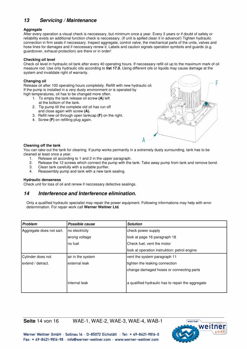
13 Servicing / Maintenance Aggregate After every operation a visual check is neccessary, but minimum once a year. Every 3 years or if doubt of safety or reliability exists an additional function check is neccessary. (If unit is spilled clean it in advance!) Tighten hydraulic connection in firm seats if neccessary. Inspect aggregate, control valve, the mechanical parts of the units, valves and hose lines for damages and if neccessary renew it. Labels and caution signals operation symbols and guards (e.g. guardcover, exhaust protection) are there or in order! Checking oil level Check oil level in hydraulic oil tank after every 40 operating hours. If neccessary refill oil up to the maximum mark of oil measure rod. Use only hydraulic oils according to list 17.0. Using different oils or liquids may cause damage at the system and invalidate right of warranty. Changing oil Release oil after 100 operating hours completely. Refilll with new hydraulic oil. If the pump is installed in a very dusty environment or is operated by high temperatures, oil has to be changed more often.
1. To empty the tank release oil screw (A) left at the bottom of the tank. 2. Tip pump till the complete old oil has run off and close again with screw (A). 3. Refill new oil through open tankcap (F) on the right. 4. Screw (F) on refilling plug again.
Cleaning off the tank You can take out the tank for cleaning. If pump works permantly in a extremely dusty surrounding, tank has to be cleaned at least once a year.
1. Release oil according to 1 and 2 in the upper paragraph. 2. Release the 12 screws which connect the pump with the tank. Take away pump from tank and remove bond. 3. Clean tank carefully with a suitable purifier. 4. Reassembly pump and tank with a new tank sealing.
Hydraulic denseness Check unit for loss of oil and renew if neccessary defective sealings.
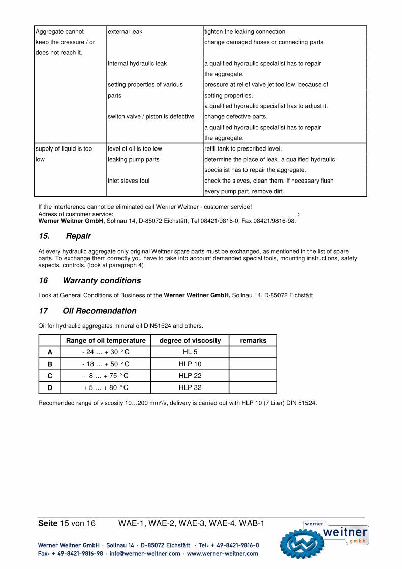
14 Interference and Interference elimination. Only a qualified hydraulic specialist may repair the power equipment. Following informations may help with error determination. For repair work call Werner Weitner Ltd.
Problem Possible cause Solution
Aggregate does not sart. no electricity check power supply
wrong voltage look at page 16 paragraph 18
no fuel Check fuel, vent the motor
look at operation instruktion: petrol engine
Cylinder does not air in the system vent the system paragraph 11
extend / detract. external leak tighten the leaking connection
change damaged hoses or connecting parts
internal leak a qualified hydraulic has to repair the aggregate
Seite 15 von 16 WAE-1, WAE-2, WAE-3, WAE-4, WAB-1
If the interference cannot be eliminated call Werner Weitner - customer service! Adress of customer service: : Werner Weitner GmbH, Sollnau 14, D-85072 Eichstätt, Tel 08421/9816-0, Fax 08421/9816-98.
15. Repair
At every hydraulic aggregate only original Weitner spare parts must be exchanged, as mentioned in the list of spare parts. To exchange them correctly you have to take into account demanded special tools, mounting instructions, safety aspects, controls. (look at paragraph 4)
16 Warranty conditions Look at General Conditions of Business of the Werner Weitner GmbH, Sollnau 14, D-85072 Eichstätt
17 Oil Recomendation Oil for hydraulic aggregates mineral oil DIN51524 and others. Recomended range of viscosity 10…200 mm²/s, delivery is carried out with HLP 10 (7 Liter) DIN 51524.
Aggregate cannot external leak tighten the leaking connection
keep the pressure / or change damaged hoses or connecting parts
does not reach it.
internal hydraulic leak a qualified hydraulic specialist has to repair
the aggregate.
setting properties of various pressure at relief valve jet too low, because of
parts setting properties.
a qualified hydraulic specialist has to adjust it.
switch valve / piston is defective change defective parts.
a qualified hydraulic specialist has to repair
the aggregate.
supply of liquid is too level of oil is too low refill tank to prescribed level.
low leaking pump parts determine the place of leak, a qualified hydraulic
specialist has to repair the aggregate.
inlet sieves foul check the sieves, clean them. If necessary flush
every pump part, remove dirt.
Range of oil temperature degree of viscosity remarks


![Offshore Windenergiestandort Sept 2018 [Kompatibilitätsmodus] · Die WAB wurde 2002 in Bremerhaven gegründet und hat ihren in der Seestadt. Das aktive Das aktive Netzwerk zählt](https://static.unterlagen.site/doc/80x56/5e0af3c9b6dc4f27b97498c9/offshore-windenergiestandort-sept-2018-kompatibilittsmodus-die-wab-wurde-2002.jpg)


