Universität Duisburg-Essen Fakultät für Ingenieurwissenschaften Fachgebiet Hochfrequenztechnik (HFT) Bachelor Thesis RDS Encoder for the Campus Broadcast Sender Poorya Hajian Supervisor: Prof. Dr.-Ing. Klaus Sollbach Zweitgutachter: Prof. Dr.-Ing. A. Beyer June 2009
Transcript
Universität Duisburg-Essen Fakultät für Ingenieurwissenschaften
Fachgebiet Hochfrequenztechnik (HFT)
Bachelor ThesisRDS Encoder for the Campus Broadcast Sender
Poorya Hajian
Supervisor:
Prof. Dr.-Ing. Klaus Sollbach
Zweitgutachter:Prof. Dr.-Ing. A. Beyer
June 2009
What is RDS Encoder?
Radio Data System, or RDS, is a communications protocol fortransmmiting small amounts of digital information like Programservice identificaton,Program identification by using conventional FMradio broadcasts to send information over a communications channelstandard from the European Broadcasting Union.
The RDS system contains several types of informationtransmitted, including time, track/artist info andstation identification which is the practice of radio ortelevision stations or networks identifying on air.
Usage of RDS
The Radio Data System, RDS, is intended for application to VHF/FM sound broadcasts in the range 87.5 MHZ to 108.0 MHZ which may carry either stereophonic (pilot‐tone system) or monophonic programs. The main objectives of RDS are to enable improved functionality for FM receivers and to make them more user‐friendly by using features such as Program Identification, Program Service name display and where applicable, automatic tuning for portable and car radios, in particular.
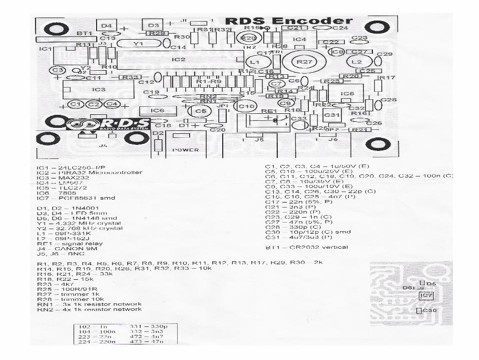
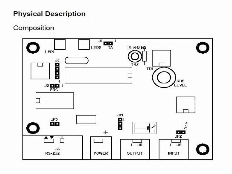
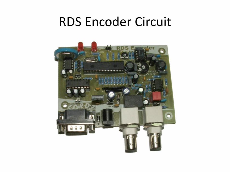
RDS Encoder Circuit
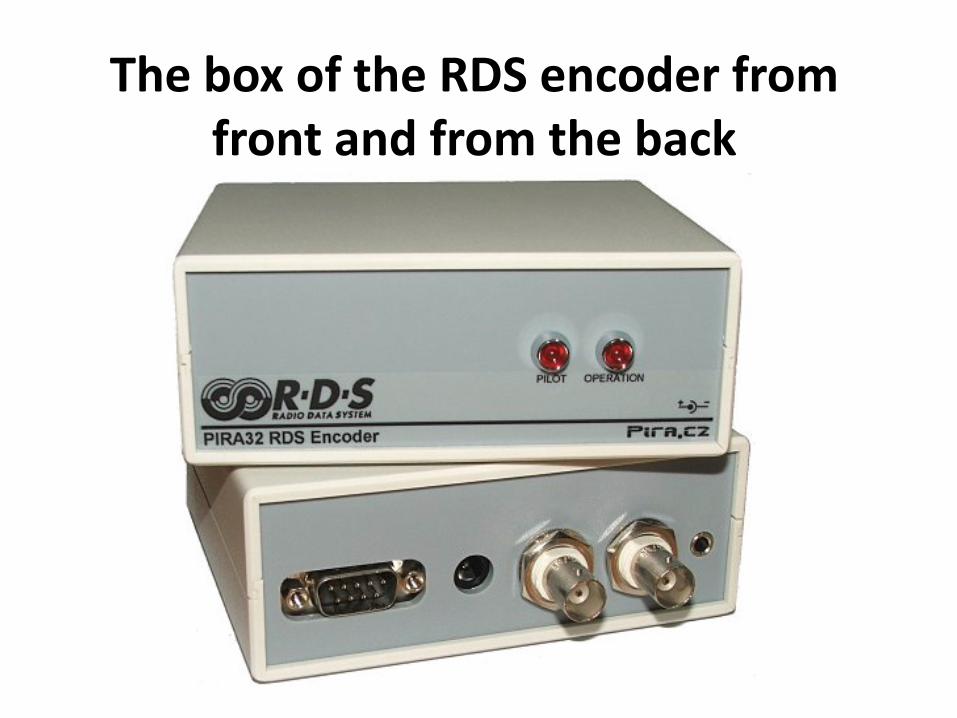
The box of the RDS encoder from front and from the back
How to connect RDS Encoder to PC?
The RDS encoder is connected directly to PC via standard serial lap‐link cable terminated by CANON D‐SUB female plugs.
We use our program to control the RDS. In fact the Magic RDS works as a Demo version software for our RDS encoder.
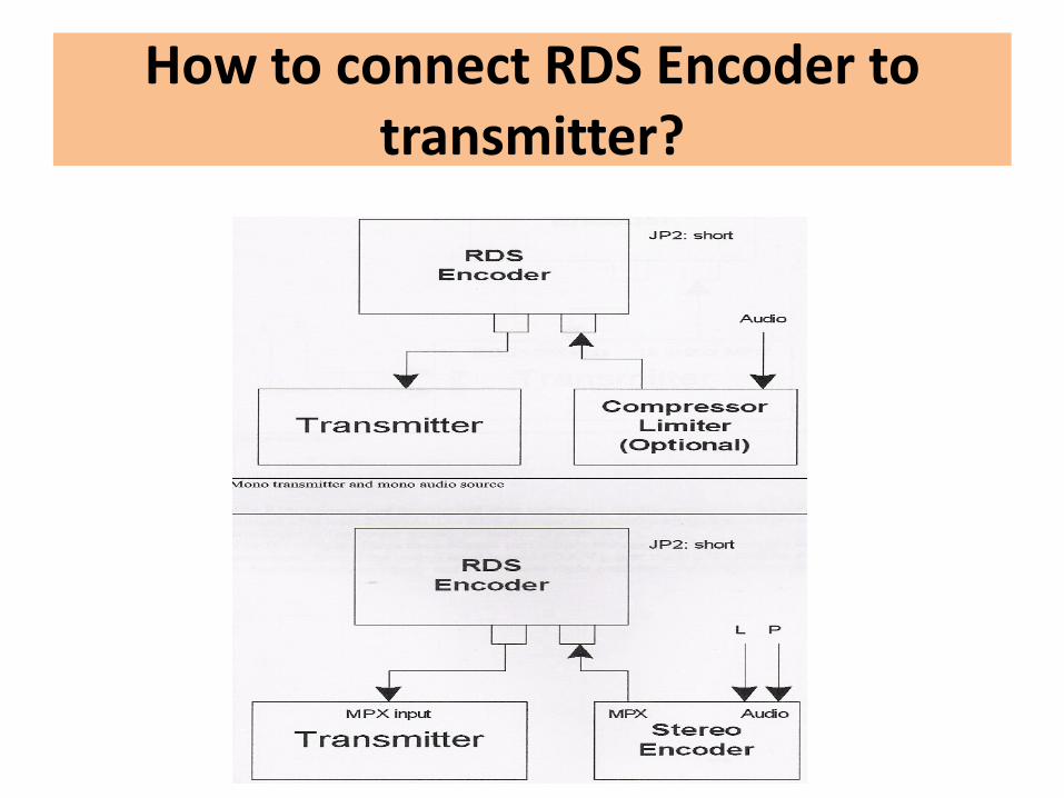
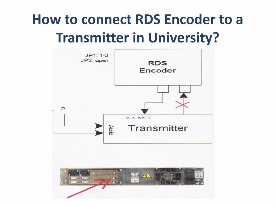
How to connect RDS Encoder to transmitter?
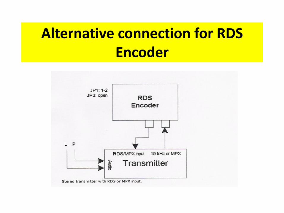
Alternative connection for RDS Encoder
The output of the RDS Encoder should beconnected to the SCA2(sub-carrier2 inputlevel adjustment) of the transmitter inorder to transmit the Program serviceidentification which is Campus FM.
Our Transmitter name is Cte broadcast 25 W FM Transmitter TX25 PLUS.
RDS Connection in Radio Campus Duisburg‐Essen University
How to connect RDS Encoder to a Transmitter in University?
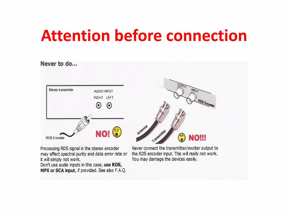
Attention before connection
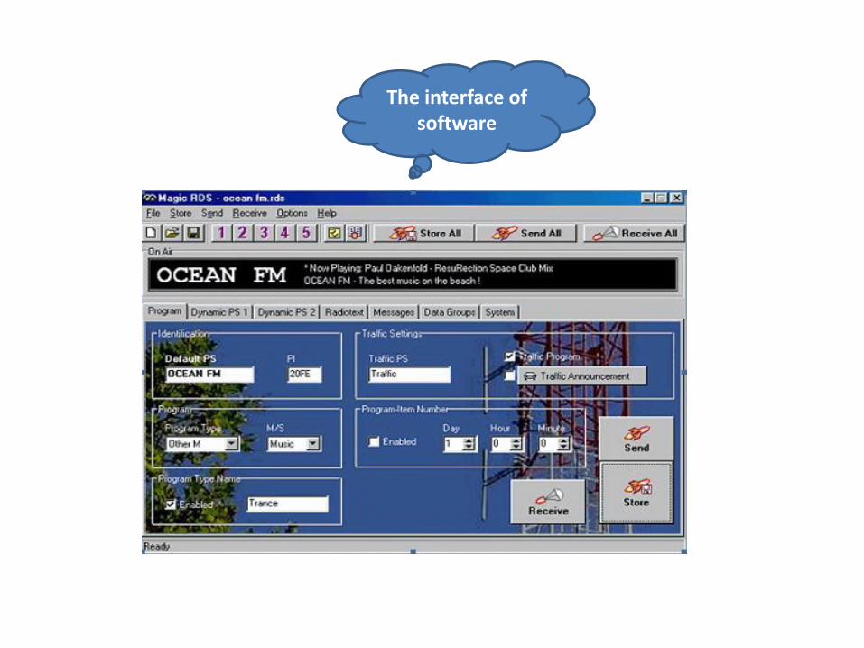
The interface of software
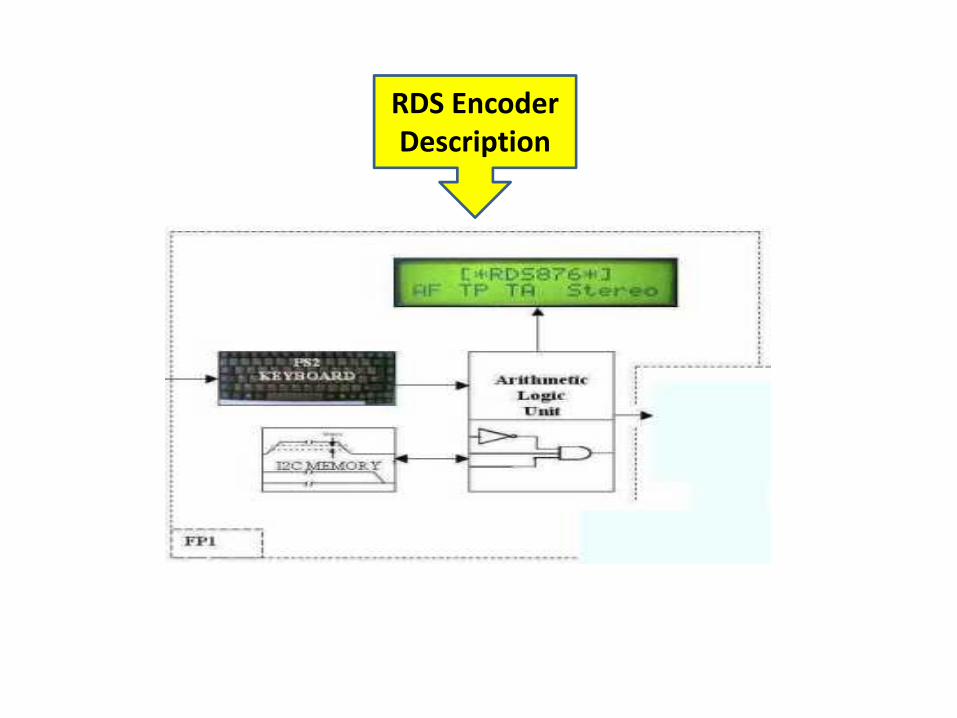
RDS Encoder Description
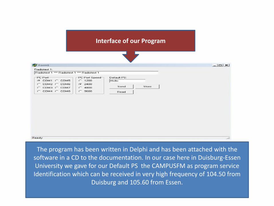
Interface of our Program
The program has been written in Delphi and has been attached with the software in a CD to the documentation. In our case here in Duisburg‐Essen University we gave for our Default PS the CAMPUSFM as program service Identification which can be received in very high frequency of 104.50 from
Duisburg and 105.60 from Essen.
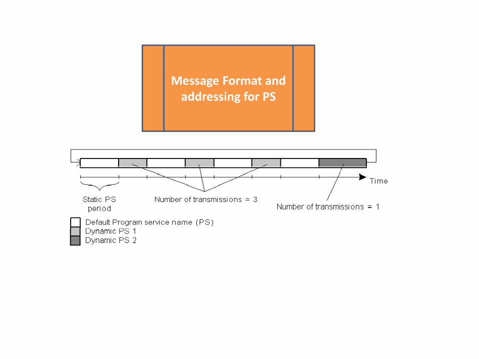
Message Format and addressing for PS
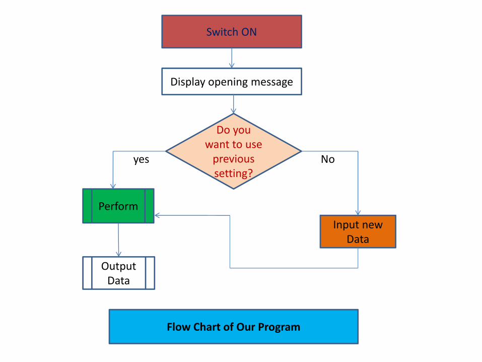
Do you want to use previous setting?
Switch ON
Display opening message
Perform
Input new Data
Output Data
yes No
Flow Chart of Our Program
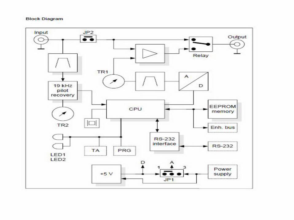
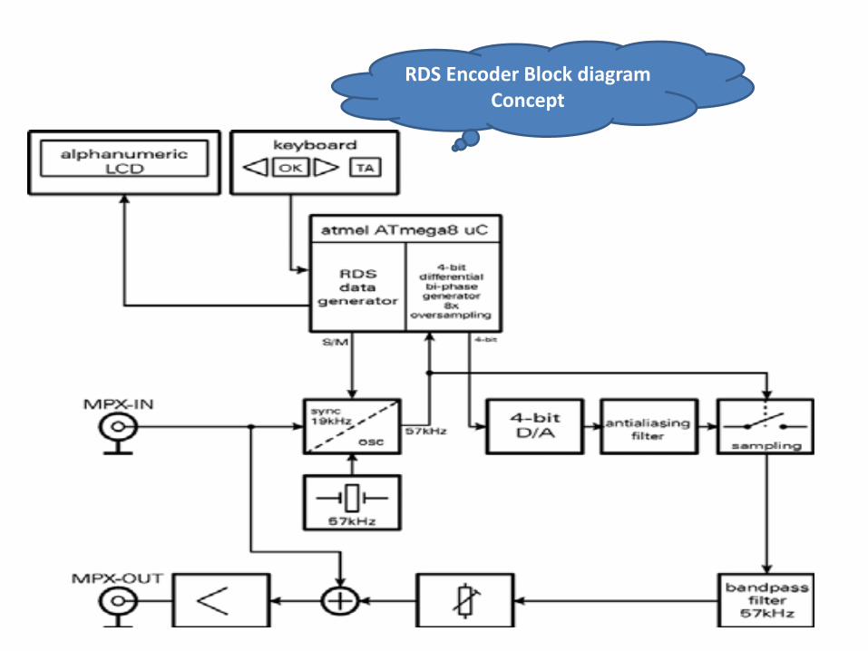
RDS Encoder Block diagram Concept
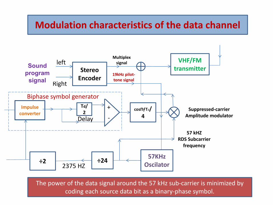
Modulation characteristics of the data channel
Stereo Encoder
VHF/FMtransmitter
57KHzOscilator
Impulse converter
Td/2
cosЃTd/4
÷2 ÷24
Right
leftSound program
signal
Multiplex signal
+
‐
Biphase symbol generator
2375 HZ
Delay
57 kHZRDS Subcarrier frequency
19kHz pilot‐tone signal
Suppressed‐carrier Amplitude modulator
The power of the data signal around the 57 kHz sub‐carrier is minimized by coding each source data bit as a binary‐phase symbol.
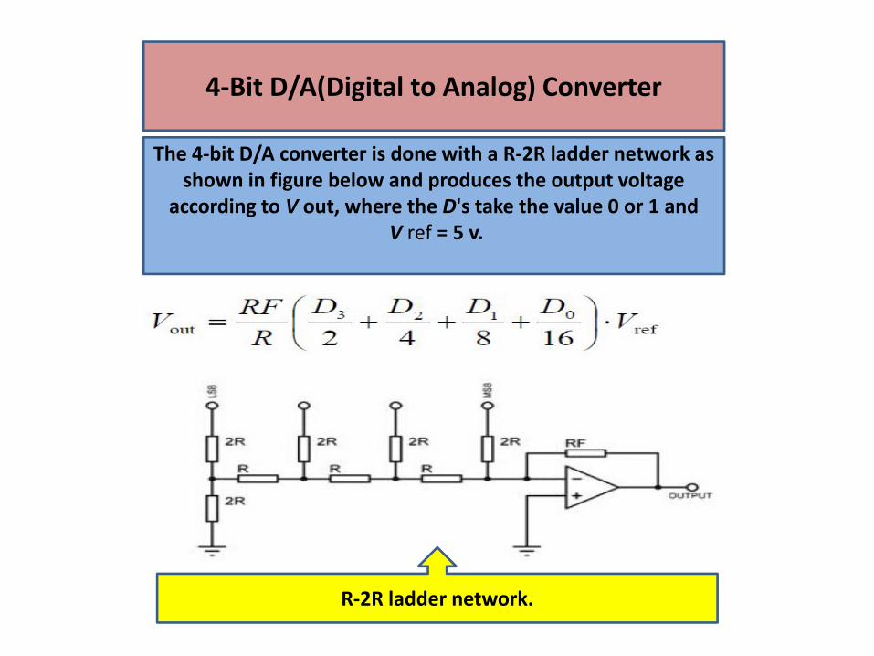
4‐Bit D/A(Digital to Analog) Converter
The 4‐bit D/A converter is done with a R‐2R ladder network as shown in figure below and produces the output voltage
according to V out, where the D's take the value 0 or 1 andV ref = 5 v.
R‐2R ladder network.
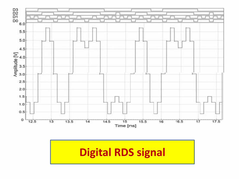
Digital RDS signal
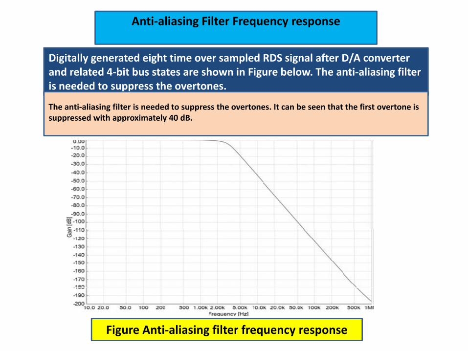
Anti‐aliasing Filter Frequency response
Digitally generated eight time over sampled RDS signal after D/A converter and related 4‐bit bus states are shown in Figure below. The anti‐aliasing filter is needed to suppress the overtones.
Figure Anti‐aliasing filter frequency response
The anti‐aliasing filter is needed to suppress the overtones. It can be seen that the first overtone is suppressed with approximately 40 dB.
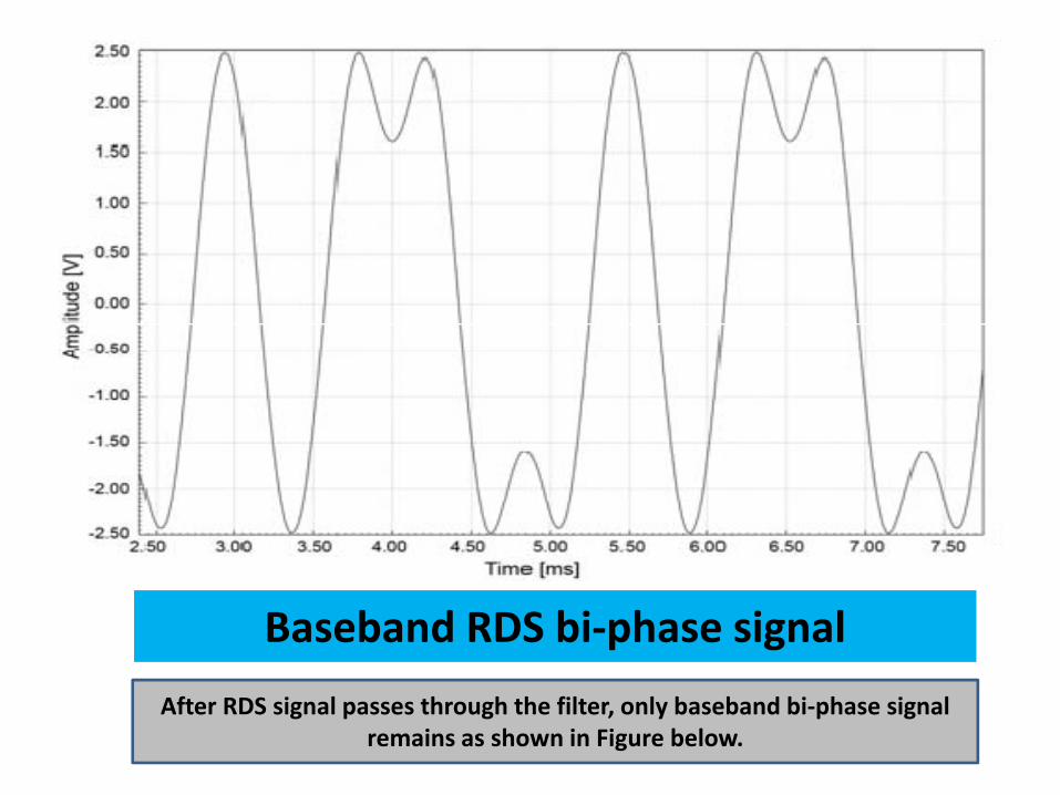
Baseband RDS bi‐phase signal
After RDS signal passes through the filter, only baseband bi‐phase signal remains as shown in Figure below.
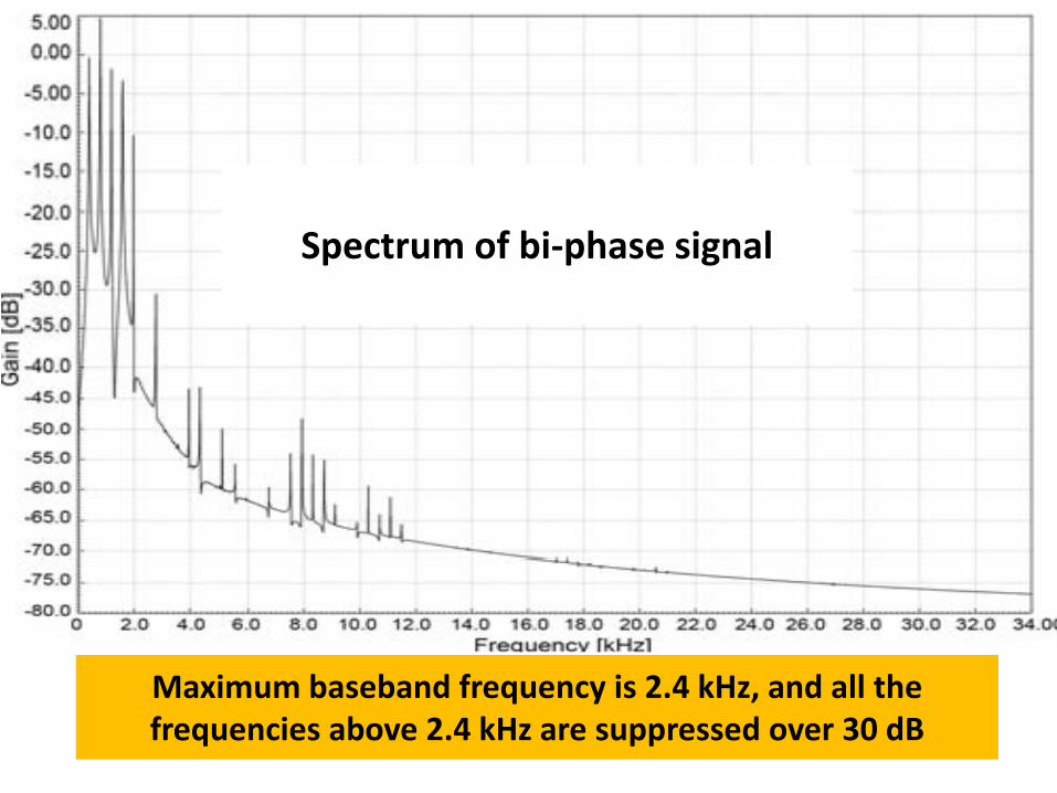
Spectrum of bi‐phase signal
Maximum baseband frequency is 2.4 kHz, and all the frequencies above 2.4 kHz are suppressed over 30 dB
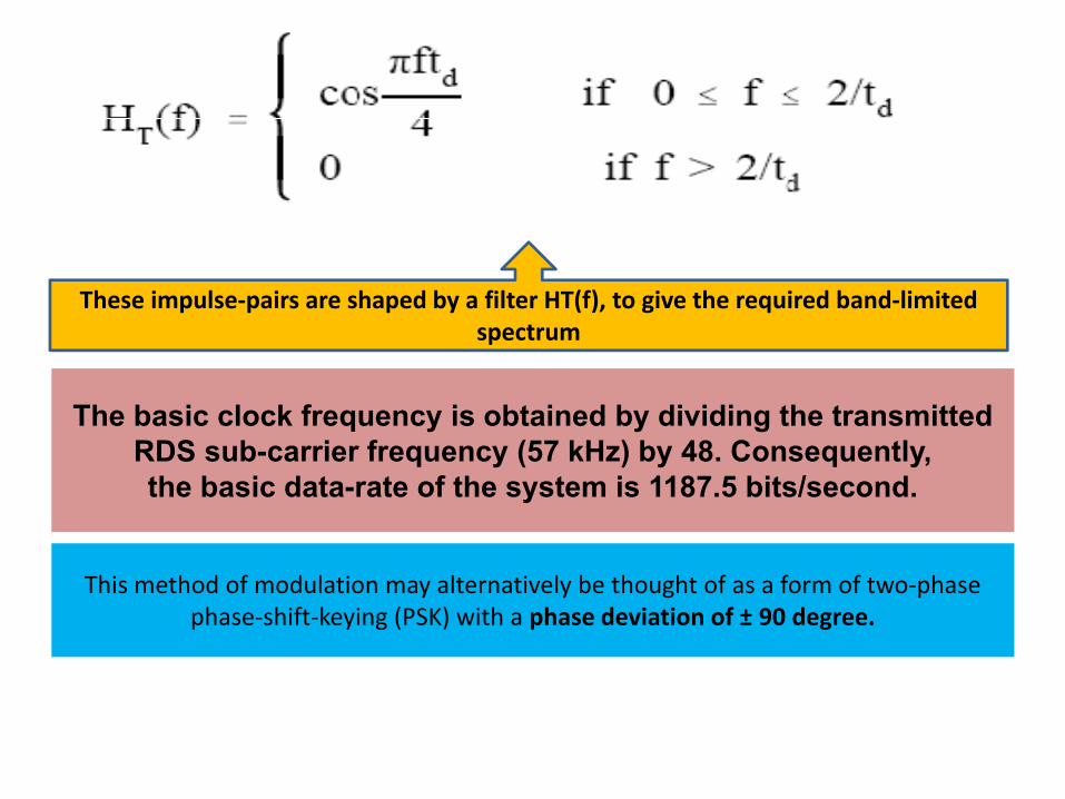
The basic clock frequency is obtained by dividing the transmitted RDS sub-carrier frequency (57 kHz) by 48. Consequently, the basic data-rate of the system is 1187.5 bits/second.
This method of modulation may alternatively be thought of as a form of two‐phase phase‐shift‐keying (PSK) with a phase deviation of ± 90 degree.
These impulse‐pairs are shaped by a filter HT(f), to give the required band‐limited spectrum
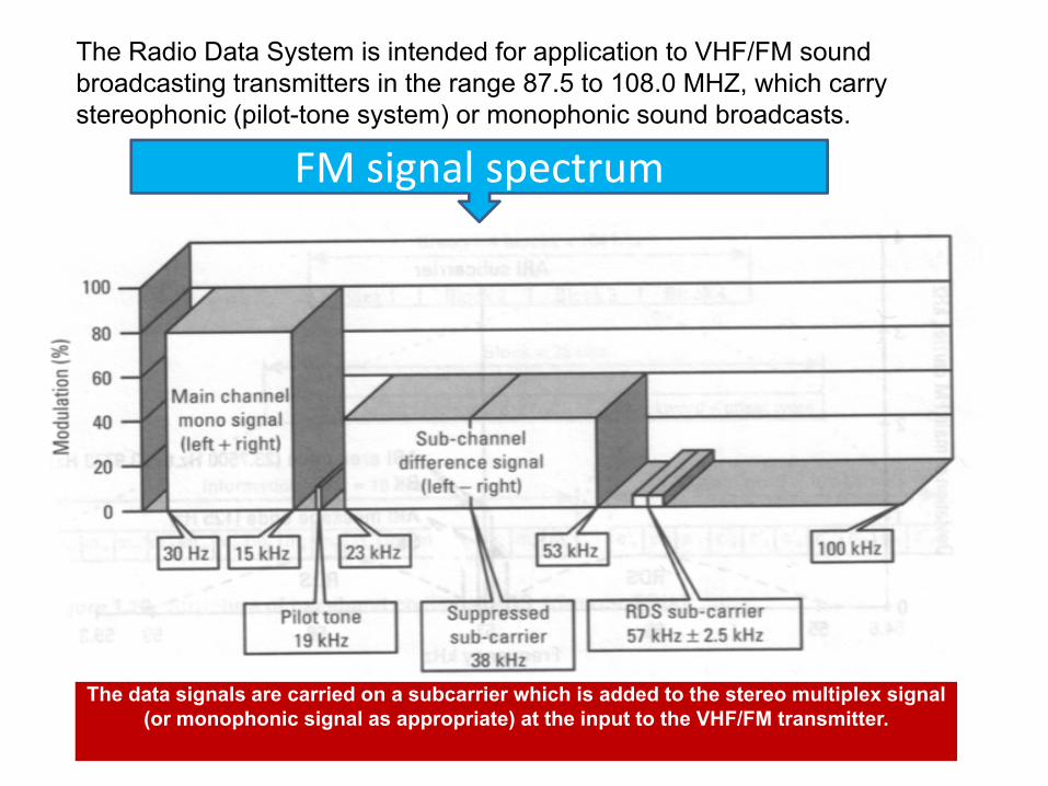
The Radio Data System is intended for application to VHF/FM sound broadcasting transmitters in the range 87.5 to 108.0 MHZ, which carry stereophonic (pilot-tone system) or monophonic sound broadcasts.
FM signal spectrum
The data signals are carried on a subcarrier which is added to the stereo multiplex signal (or monophonic signal as appropriate) at the input to the VHF/FM transmitter.
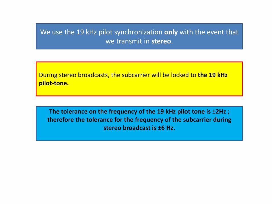
We use the 19 kHz pilot synchronization only with the event that we transmit in stereo.
During stereo broadcasts, the subcarrier will be locked to the 19 kHzpilot‐tone.
The tolerance on the frequency of the 19 kHz pilot tone is ±2Hz ; therefore the tolerance for the frequency of the subcarrier during
stereo broadcast is ±6 Hz.
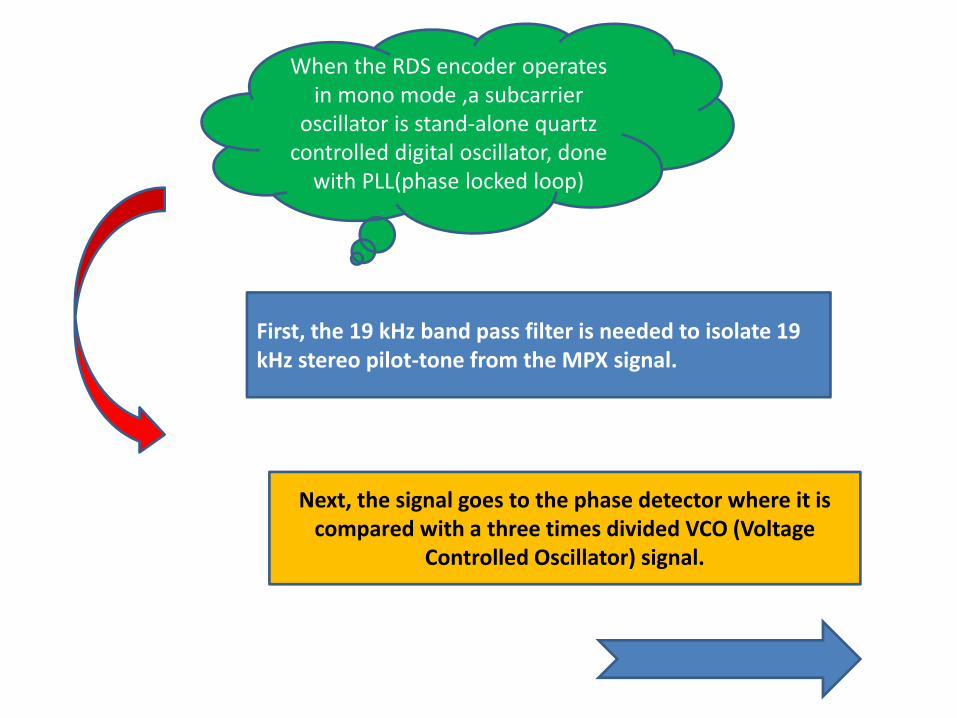
When the RDS encoder operates in mono mode ,a subcarrier
oscillator is stand‐alone quartz controlled digital oscillator, done with PLL(phase locked loop)
First, the 19 kHz band pass filter is needed to isolate 19 kHz stereo pilot‐tone from the MPX signal.
Next, the signal goes to the phase detector where it is compared with a three times divided VCO (Voltage
Controlled Oscillator) signal.
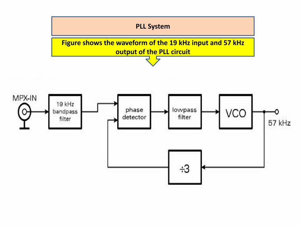
PLL System
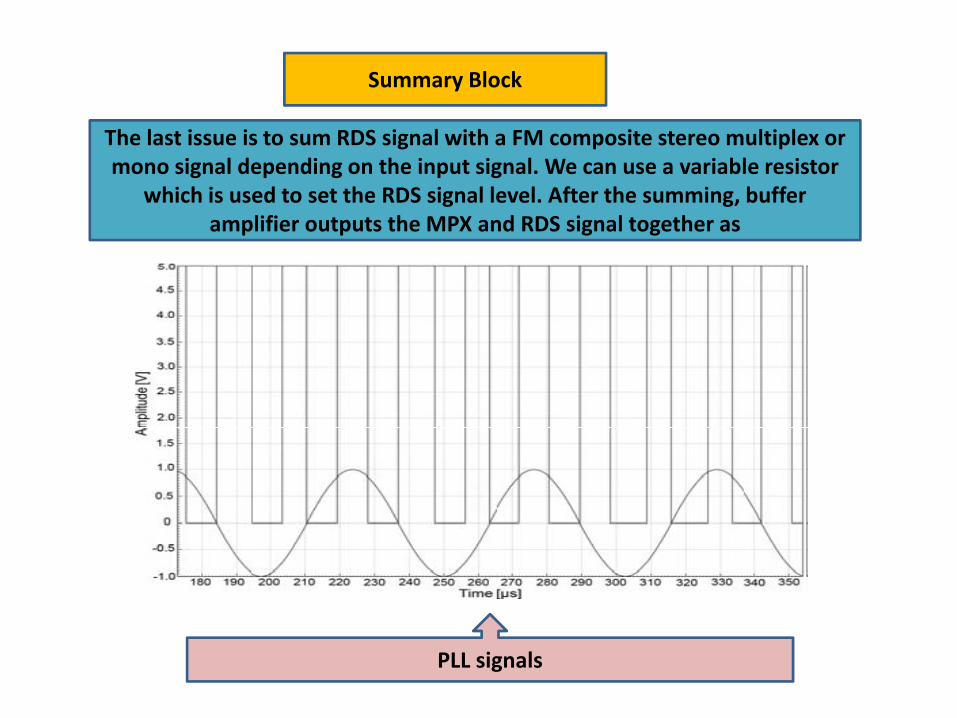
Figure shows the waveform of the 19 kHz input and 57 kHz output of the PLL circuit
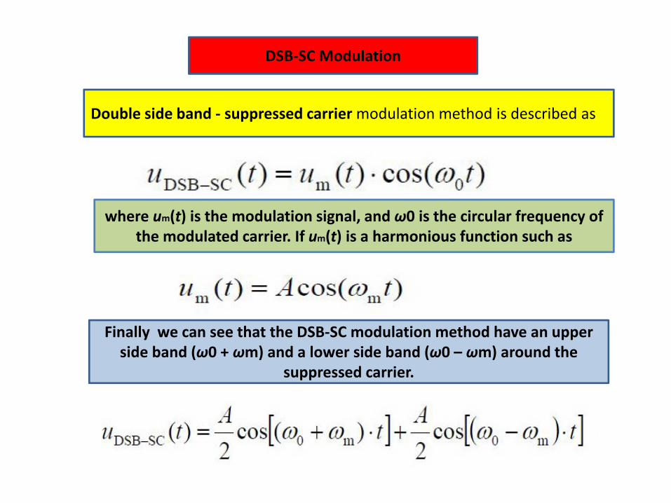
DSB‐SC Modulation
Double side band ‐ suppressed carriermodulation method is described as
where um(t) is the modulation signal, and ω0 is the circular frequency of the modulated carrier. If um(t) is a harmonious function such as
Finally we can see that the DSB‐SC modulation method have an upper side band (ω0 + ωm) and a lower side band (ω0 – ωm) around the
suppressed carrier.
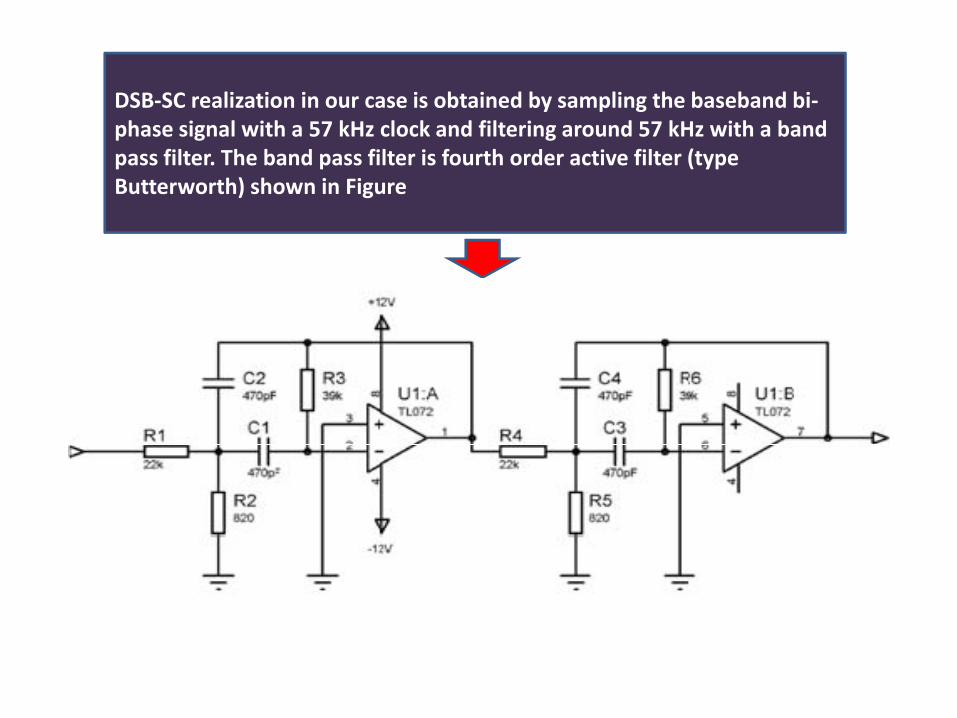
DSB‐SC realization in our case is obtained by sampling the baseband bi‐phase signal with a 57 kHz clock and filtering around 57 kHz with a band pass filter. The band pass filter is fourth order active filter (type Butterworth) shown in Figure
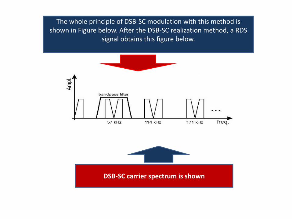
The whole principle of DSB‐SC modulation with this method is shown in Figure below. After the DSB‐SC realization method, a RDS
signal obtains this figure below.
DSB‐SC carrier spectrum is shown
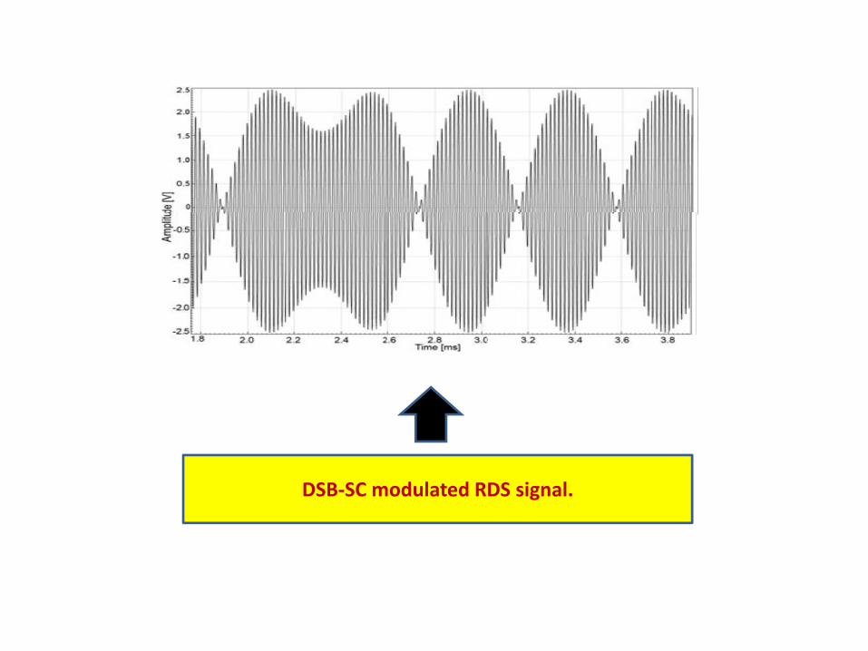
DSB‐SC modulated RDS signal.
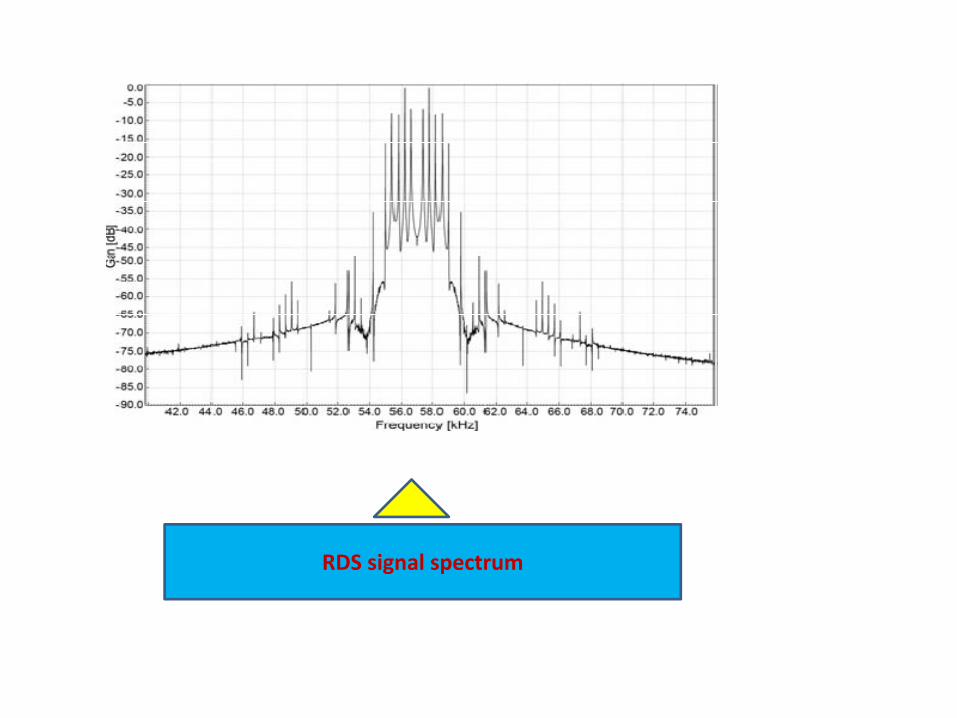
RDS signal spectrum
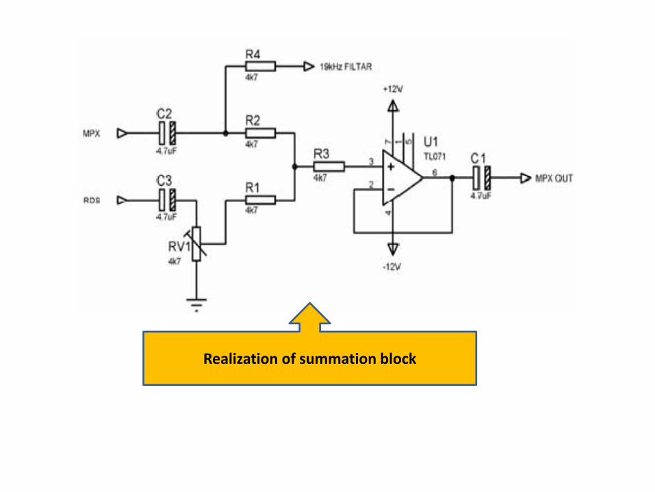
Summary Block
The last issue is to sum RDS signal with a FM composite stereo multiplex or mono signal depending on the input signal. We can use a variable resistor
which is used to set the RDS signal level. After the summing, buffer amplifier outputs the MPX and RDS signal together as
PLL signals
Realization of summation block
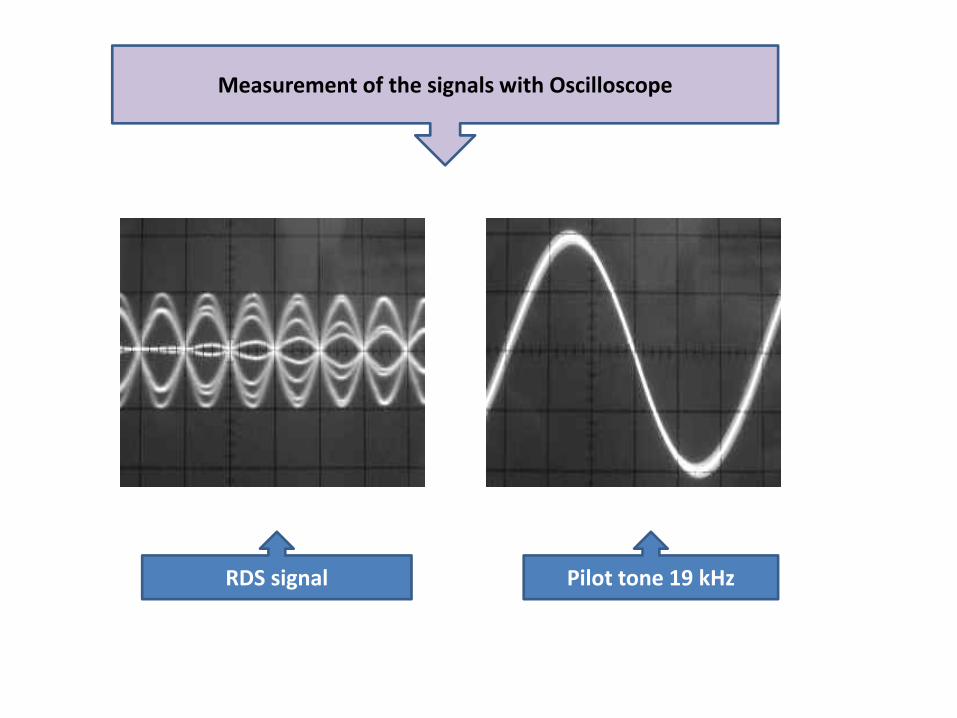
Measurement of the signals with Oscilloscope
RDS signal Pilot tone 19 kHz
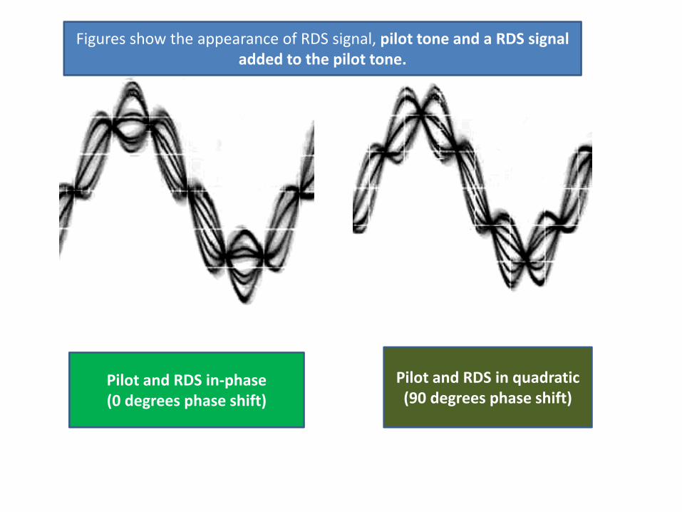
Pilot and RDS in‐phase(0 degrees phase shift)
Pilot and RDS in quadratic(90 degrees phase shift)
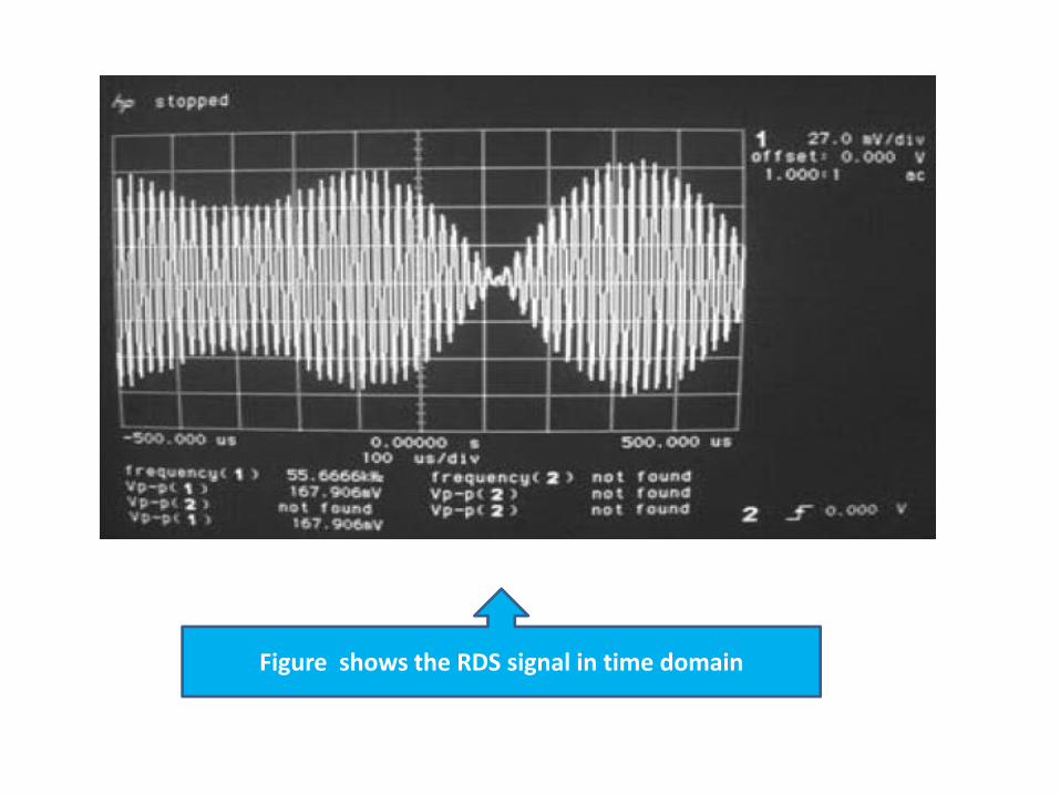
Figures show the appearance of RDS signal, pilot tone and a RDS signal added to the pilot tone.
Figure shows the RDS signal in time domain
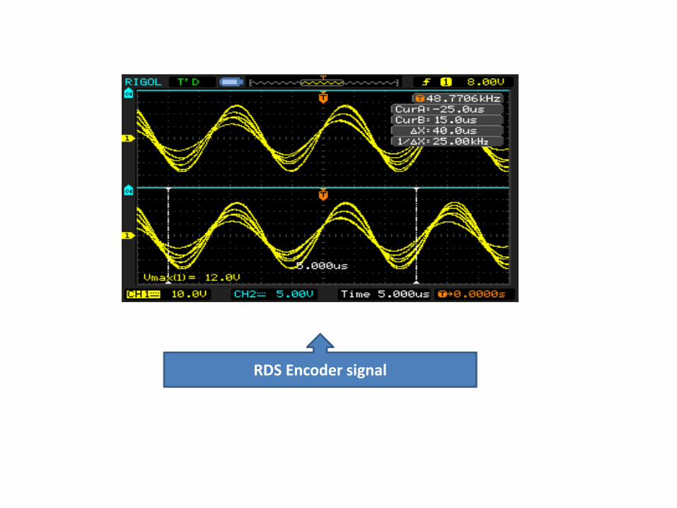
RDS Encoder signal
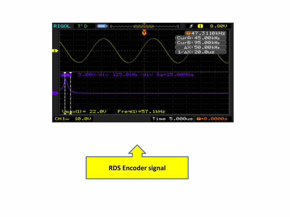
RDS Encoder signal
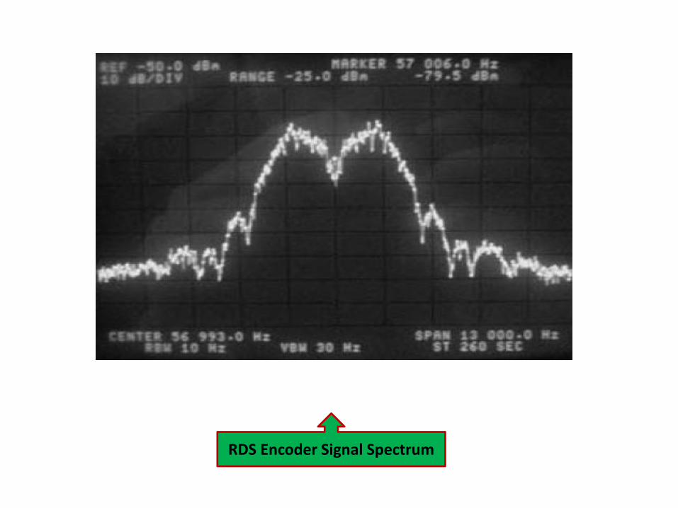
RDS Encoder Signal Spectrum
Conclusion
The goal was to make simple RDS Encoder which transmits the Program Service Identification which is Campus FM. That is done using a RDS Encoder which can be used to connect to a PC and a transmitter for collecting data and for generating bi‐phase signal. RDS encoder was tested on air with FM transmitter and it worked within expectations.Future work on RDS encoder is to implement radio text (RT), enhanced other network information (EON) and clock time (CT) and M/S Music Speech.