56
DE EN DE EN DE EN DE EN DE EN DE EN DE EN DE EN DE Handbuch Manual Additional languages www.r-stahl.com DE EN Betätigungsvorsätze Actuators Reihe 8602/3 Series 8602/3
DEEN
DEEN
DEEN
DEEN
DEEN
DEEN
DEEN
DEEN
DE
HandbuchManual
Additional languages www.r-stahl.com DE EN
Betätigungsvorsätze
Actuators
Reihe 8602/3
Series 8602/3

DEEN
DEEN
DEEN
DEEN
DEEN
DEEN
DEEN
DEEN
DE
DEDEDEDEDEDEDEDEDEDEDEDEDEDEDEDEDEDEDEDEDEDEDEDEDE
HandbuchAdditional languages www.stahl-ex.com
DE
Betätigungsvorsätze
Reihe 8602/3
2 BetätigungsvorsätzeReihe 8602/3
DEDEDEDEDEDEDEDEDEDEDEDEDEDEDEDEDEDEDEDEDEDEDEDEDE
Inhaltsverzeichnis1 Allgemeine Angaben ...........................................................................................31.1 Hersteller .............................................................................................................31.2 Angaben zum Handbuch ....................................................................................31.3 Weitere Dokumente ............................................................................................31.4 Konformität zu Normen und Bestimmungen .......................................................32 Erläuterung der Symbole ....................................................................................32.1 Symbole im Handbuch ........................................................................................32.2 Warnhinweise .....................................................................................................42.3 Symbole am Gerät ..............................................................................................43 Sicherheitshinweise ............................................................................................53.1 Aufbewahrung des Handbuchs ...........................................................................53.2 Sichere Verwendung ...........................................................................................53.3 Umbauten und Änderungen ................................................................................64 Funktion und Geräteaufbau ................................................................................64.1 Funktion ..............................................................................................................65 Technische Daten ...............................................................................................76 Transport und Lagerung .....................................................................................87 Montage und Installation .....................................................................................87.1 Maßangaben / Befestigungsmaße ......................................................................87.2 Montage / Demontage, Gebrauchslage ............................................................148 Inbetriebnahme .................................................................................................279 Instandhaltung, Wartung, Reparatur .................................................................279.1 Instandhaltung ..................................................................................................279.2 Wartung ............................................................................................................279.3 Reparatur ..........................................................................................................279.4 Rücksendung ....................................................................................................2810 Entsorgung ........................................................................................................2811 Zubehör und Ersatzteile ...................................................................................28
229711 / 86026123002017-07-26·HB00·III·de·01
Allgemeine Angaben
3BetätigungsvorsätzeReihe 8602/3
DEDEDEDEDEDEDEDEDEDEDEDEDEDEDEDEDEDEDEDEDEDEDEDEDE
1 Allgemeine Angaben
1.1 HerstellerR. STAHL Schaltgeräte GmbHAm Bahnhof 3074638 Waldenburg Germany
Tel.: +49 7942 943-0Fax: +49 7942 943-4333Internet: www.stahl-ex.comE-Mail: [email protected]
1.2 Angaben zum HandbuchID-Nr.: 229711 / 8602612300Publikationsnummer: 2017-07-26·HB00·III·de·01
1.3 Weitere Dokumente• Datenblatt• BetriebsanleitungDokumente in weiteren Sprachen, siehe www.stahl-ex.com.
1.4 Konformität zu Normen und BestimmungenSiehe Zertifikate und EU-Konformitätserklärung: www.stahl-ex.com.
2 Erläuterung der Symbole
2.1 Symbole im HandbuchSymbol Bedeutung
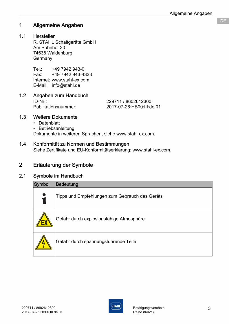
Tipps und Empfehlungen zum Gebrauch des Geräts
Gefahr durch explosionsfähige Atmosphäre
Gefahr durch spannungsführende Teile
Erläuterung der Symbole
4 229711 / 86026123002017-07-26·HB00·III·de·01
BetätigungsvorsätzeReihe 8602/3
DEDEDEDEDEDEDEDEDEDEDEDEDEDEDEDEDEDEDEDEDEDEDEDEDE
2.2 WarnhinweiseWarnhinweise unbedingt befolgen, um das konstruktive und durch den Betrieb bedingte Risiko zu minimieren. Die Warnhinweise sind wie folgt aufgebaut:• Signalwort: GEFAHR, WARNUNG, VORSICHT, HINWEIS• Art und Quelle der Gefahr/des Schadens• Folgen der Gefahr• Ergreifen von Gegenmaßnahmen zum Vermeiden der Gefahr bzw. des Schadens
2.3 Symbole am Gerät
GEFAHRGefahren für PersonenNichtbeachtung der Anweisung führt zu schweren oder tödlichen Verletzungen bei Personen.
WARNUNGGefahren für PersonenNichtbeachtung der Anweisung kann zu schweren oder tödlichen Verletzungen bei Personen führen.
VORSICHTGefahren für PersonenNichtbeachtung der Anweisung kann zu leichten Verletzungen bei Personen führen.
HINWEISVermeidung von SachschadenNichtbeachtung der Anweisung kann zu einem Sachschaden am Gerät und/oder seiner Umgebung führen.
Symbol Bedeutung
16338E00
Benannte Stelle für Qualitätsüberwachung.
02198E00
Gerät gemäß Kennzeichnung für explosionsgefährdete Bereiche zertifiziert.
229711 / 86026123002017-07-26·HB00·III·de·01
Sicherheitshinweise
5BetätigungsvorsätzeReihe 8602/3
DEDEDEDEDEDEDEDEDEDEDEDEDEDEDEDEDEDEDEDEDEDEDEDEDE
3 Sicherheitshinweise
3.1 Aufbewahrung des Handbuchs• Handbuch sorgfältig lesen.• Handbuch am Einbauort des Geräts aufbewahren.• Mitgeltende Dokumente und Betriebsanleitungen der anzuschließenden Geräte
beachten.
3.2 Sichere VerwendungVor der Montage• Sicherheitshinweise in diesem Handbuch lesen und beachten!• Sicherstellen, dass der Inhalt dieses Handbuchs vom zuständigen Personal voll
verstanden wurde.• Gerät nur bestimmungsgemäß und nur für den zugelassenen Einsatzzweck
verwenden.• Bei Betriebsbedingungen, die durch die technischen Daten des Geräts nicht
abgedeckt werden, unbedingt bei der R. STAHL Schaltgeräte GmbH rückfragen.• Sicherstellen, dass das Gerät unbeschädigt ist.• Für Schäden, die durch fehlerhaften oder unzulässigen Einsatz des Geräts sowie
durch Nichtbeachtung dieses Handbuchs entstehen, besteht keine Haftung.
Bei Montage und Installation• Nationale Montage- und Errichtungsvorschriften beachten (z.B. IEC/EN 60079-14).• Nationale Sicherheits- und Unfallverhütungsvorschriften beachten.• Bei Installation und im Betrieb die Angaben
(Kennwerte und Bemessungsbetriebsbedingungen) auf Typ- und Datenschildern sowie die Hinweisschilder am Gerät beachten.
• Vor Installation sicherstellen, dass das Gerät unbeschädigt ist.
• Lackierte, metallische Schutzkragen nicht in Bereichen einsetzen, in denen stark ladungserzeugende Prozesse, maschinelle Reib- und Trennprozesse, das Sprühen von Elektronen (z.B. im Umfeld von elektrostatischen Lackiereinrichtungen) sowie pneumatisch geförderter Staub austreten.
Wartung, Reparatur, Inbetriebnahme• Vor Inbetriebnahme sicherstellen, dass das Gerät unbeschädigt ist.• Arbeiten am Gerät, wie Installation, Instandhaltung, Wartung, Störungsbeseitigung,
nur von dazu befugtem und entsprechend geschultem Personal durchführen lassen.• Nur Wartungsarbeiten bzw. Reparaturen durchführen, die in diesem Handbuch
beschrieben sind.
Funktion und Geräteaufbau
6 229711 / 86026123002017-07-26·HB00·III·de·01
BetätigungsvorsätzeReihe 8602/3
DEDEDEDEDEDEDEDEDEDEDEDEDEDEDEDEDEDEDEDEDEDEDEDEDE
3.3 Umbauten und Änderungen
4 Funktion und Geräteaufbau
4.1 FunktionEinsatzbereichDie Betätigungsvorsätze 8602/3 sind zum Einbau in Gehäusewände und -deckel elektrischer Betriebsmittel bzw. von Schalttafeln der Zündschutzart Erhöhte Sicherheit "e" und Schutz durch Gehäuse "tb" vorgesehen. Die Komponenten sind für den Einsatz in explosionsgefährdeten Bereichen der Zonen 1, 2, 21 und 22 zertifiziert.
GEFAHRExplosionsgefahr durch Umbauten und Änderungen am Gerät! Nichtbeachten führt zu schweren oder tödlichen Verletzungen.
• Gerät nicht umbauen oder verändern.
Für Schäden, die durch Umbauten und Änderungen entstehen, besteht keine Haftung und keine Gewährleistung.
GEFAHRExplosionsgefahr durch zweckentfremdete Verwendung!Nichtbeachten führt zu schweren oder tödlichen Verletzungen.
• Gerät nur entsprechend den in diesem Handbuch festgelegten Betriebsbedingungen verwenden.
• Gerät nur entsprechend dem in diesem Handbuch genannten Einsatzzweck verwenden.
229711 / 86026123002017-07-26·HB00·III·de·01
Technische Daten
7BetätigungsvorsätzeReihe 8602/3
DEDEDEDEDEDEDEDEDEDEDEDEDEDEDEDEDEDEDEDEDEDEDEDEDE
5 Technische Daten
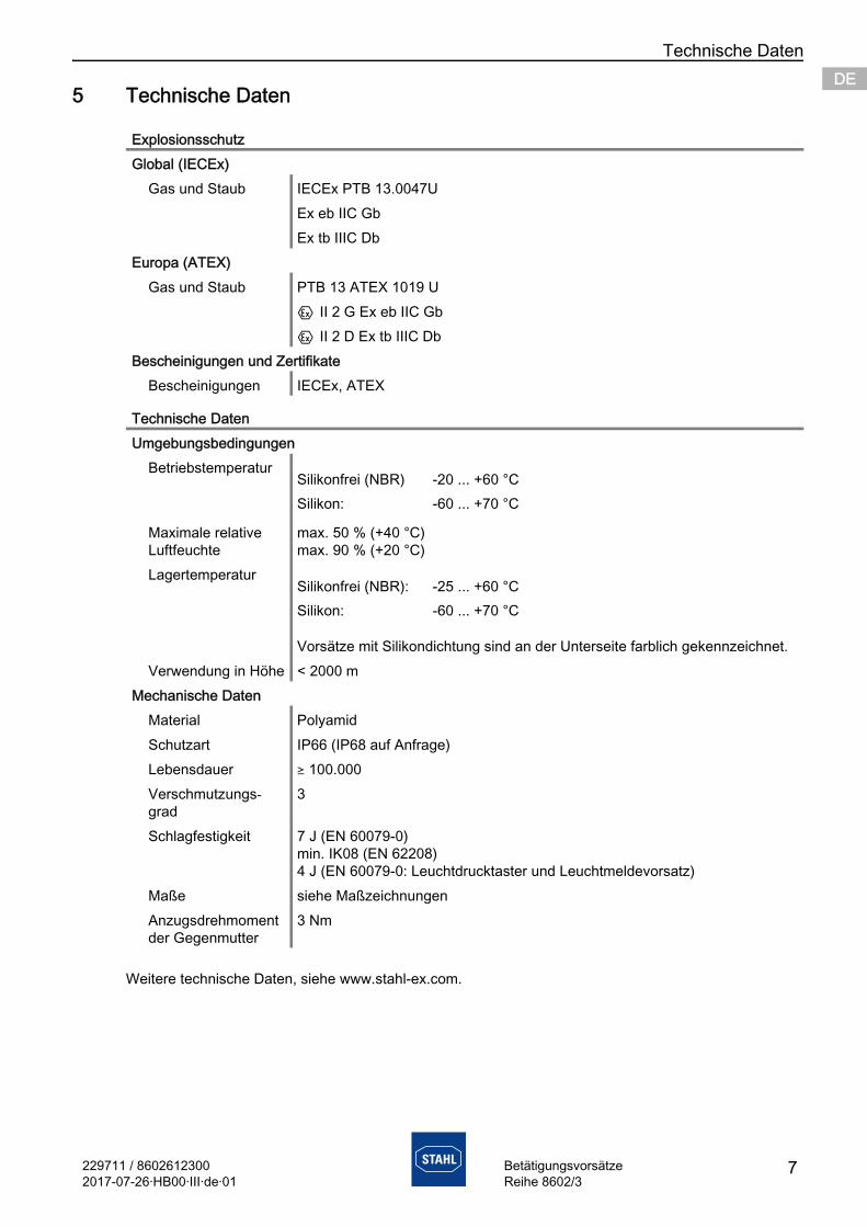
Weitere technische Daten, siehe www.stahl-ex.com.
ExplosionsschutzGlobal (IECEx)
Gas und Staub IECEx PTB 13.0047UEx eb IIC GbEx tb IIIC Db
Europa (ATEX)Gas und Staub PTB 13 ATEX 1019 U
E II 2 G Ex eb IIC GbE II 2 D Ex tb IIIC Db
Bescheinigungen und ZertifikateBescheinigungen IECEx, ATEX
Technische DatenUmgebungsbedingungen
Betriebstemperatur
Maximale relative Luftfeuchte
max. 50 % (+40 °C)max. 90 % (+20 °C)
Lagertemperatur
Vorsätze mit Silikondichtung sind an der Unterseite farblich gekennzeichnet.Verwendung in Höhe < 2000 m
Mechanische DatenMaterial PolyamidSchutzart IP66 (IP68 auf Anfrage) Lebensdauer ) 100.000Verschmutzungs-grad
3
Schlagfestigkeit 7 J (EN 60079-0)min. IK08 (EN 62208)4 J (EN 60079-0: Leuchtdrucktaster und Leuchtmeldevorsatz)
Maße siehe MaßzeichnungenAnzugsdrehmoment der Gegenmutter
3 Nm
Silikonfrei (NBR) -20 ... +60 °CSilikon: -60 ... +70 °C
Silikonfrei (NBR): -25 ... +60 °CSilikon: -60 ... +70 °C
Transport und Lagerung
8 229711 / 86026123002017-07-26·HB00·III·de·01
BetätigungsvorsätzeReihe 8602/3
DEDEDEDEDEDEDEDEDEDEDEDEDEDEDEDEDEDEDEDEDEDEDEDEDE
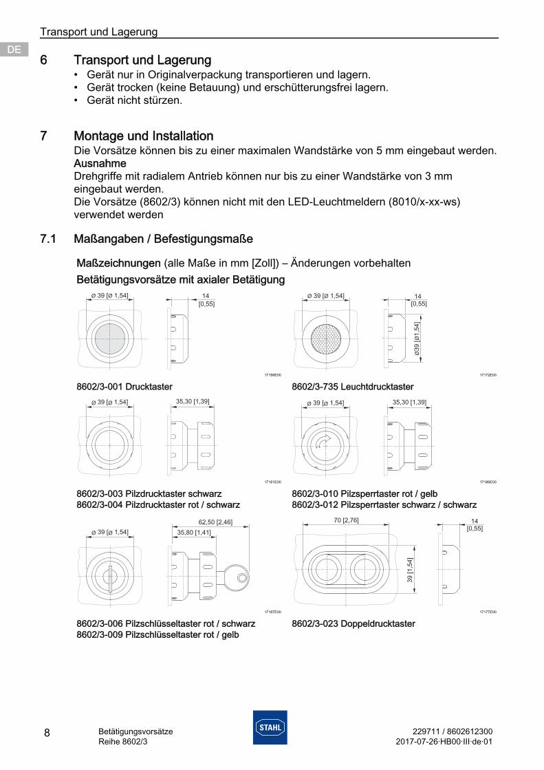
6 Transport und Lagerung• Gerät nur in Originalverpackung transportieren und lagern.• Gerät trocken (keine Betauung) und erschütterungsfrei lagern.• Gerät nicht stürzen.
7 Montage und InstallationDie Vorsätze können bis zu einer maximalen Wandstärke von 5 mm eingebaut werden.AusnahmeDrehgriffe mit radialem Antrieb können nur bis zu einer Wandstärke von 3 mm eingebaut werden.Die Vorsätze (8602/3) können nicht mit den LED-Leuchtmeldern (8010/x-xx-ws) verwendet werden
7.1 Maßangaben / Befestigungsmaße
Maßzeichnungen (alle Maße in mm [Zoll]) – Änderungen vorbehaltenBetätigungsvorsätze mit axialer Betätigung
17188E00 17172E00
8602/3-001 Drucktaster 8602/3-735 Leuchtdrucktaster
17181E00 17186E00
8602/3-003 Pilzdrucktaster schwarz8602/3-004 Pilzdrucktaster rot / schwarz
8602/3-010 Pilzsperrtaster rot / gelb8602/3-012 Pilzsperrtaster schwarz / schwarz
17187E00 17177E00
8602/3-006 Pilzschlüsseltaster rot / schwarz8602/3-009 Pilzschlüsseltaster rot / gelb
8602/3-023 Doppeldrucktaster
Ø Ø39 [ 1,54] 14
[0,55]14
ØØ
39 [
1,5
4]
[0,55]
Ø Ø39 [ 1,54]
35,30 [1,39]Ø Ø39 [ 1,54] 35,30 [1,39]Ø Ø39 [ 1,54]
35,80 [1,41]Ø Ø39 [ 1,54]
62,50 [2,46]
39
[1
,54
]
70 [2,76] 14[0,55]
229711 / 86026123002017-07-26·HB00·III·de·01
Montage und Installation
9BetätigungsvorsätzeReihe 8602/3
DEDEDEDEDEDEDEDEDEDEDEDEDEDEDEDEDEDEDEDEDEDEDEDEDE
17180E00 17349E00
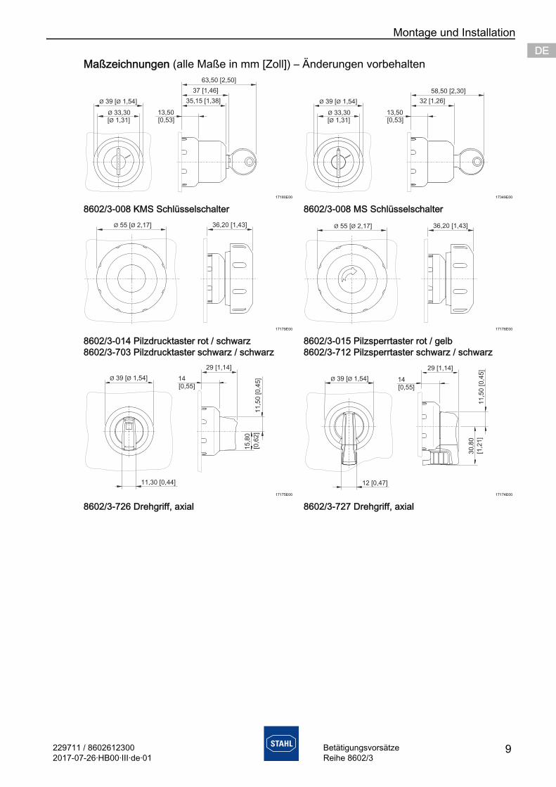
8602/3-008 KMS Schlüsselschalter 8602/3-008 MS Schlüsselschalter
17179E00 17178E00
8602/3-014 Pilzdrucktaster rot / schwarz8602/3-703 Pilzdrucktaster schwarz / schwarz
8602/3-015 Pilzsperrtaster rot / gelb8602/3-712 Pilzsperrtaster schwarz / schwarz
17175E00 17174E00
8602/3-726 Drehgriff, axial 8602/3-727 Drehgriff, axial
Maßzeichnungen (alle Maße in mm [Zoll]) – Änderungen vorbehalten
Ø Ø39 [ 1,54]
[ 1,31]Ø
Ø 33,30 13,50[0,53]
35,15 [1,38]
37 [1,46]
63,50 [2,50]
Ø Ø39 [ 1,54]
[ 1,31]Ø
Ø 33,30 13,50[0,53]
32 [1,26]
58,50 [2,30]
36,20 [1,43]Ø Ø55 [ 2,17] 36,20 [1,43]Ø Ø55 [ 2,17]
Ø Ø39 [ 1,54]
11,30 [0,44]
14
[0,5 ]5
29 [1,14]
15,8
0
[0,6
2]
11,5
0 [0,4
5] Ø Ø39 [ 1,54]
12 [0,47]
30,8
0
11,5
0 [0,4
5]
14
[0,5 ]5
29 [1,14]
[1,2
1]
Montage und Installation
10 229711 / 86026123002017-07-26·HB00·III·de·01
BetätigungsvorsätzeReihe 8602/3
DEDEDEDEDEDEDEDEDEDEDEDEDEDEDEDEDEDEDEDEDEDEDEDEDE
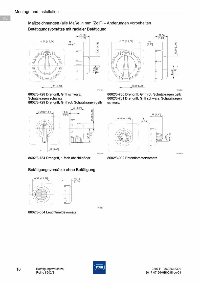
Betätigungsvorsätze mit radialer Betätigung
17184E00 17182E00
8602/3-728 Drehgriff, Griff schwarz, Schutzkragen schwarz8602/3-729 Drehgriff, Griff rot, Schutzkragen gelb
8602/3-730 Drehgriff, Griff rot, Schutzkragen gelb8602/3-731 Drehgriff, Griff schwarz, Schutzkragen schwarz
17183E00 17176E00
8602/3-734 Drehgriff, 1 fach abschließbar 8602/3-092 Potentiometervorsatz
Betätigungsvorsätze ohne Betätigung
17185E00
8602/3-054 Leuchtmeldevorsatz
Maßzeichnungen (alle Maße in mm [Zoll]) – Änderungen vorbehalten
0OFF
I
ON
Ø Ø65 [ 2,56] 16
29,80
[0,63]
19
,30
[0,7
6]
19
,80
[0
,78
]
14 [0,55]
[1,17]
0OFF
16,50 [0,65]
I
ON
Ø Ø65 [ 2,56]
30,3
0
19,8
0 [0,7
8]16
[0,63]
27,50[1,08]
[1,1
9]
30,8
0
14,10
[0,56]
29 [1,14]
11,5
0 [0,4
5]
Ø Ø39 [ 1,54]
[1,2
1]
12 [0,47]
12
6
3
45
0
Ø Ø39 [ 1,54]
Ø19
[0,7
5]
Ø
14
[0,5 ]5
28 [1,10]
16,18[0,65]
39 [ 1,54]Ø Ø
229711 / 86026123002017-07-26·HB00·III·de·01
Montage und Installation
11BetätigungsvorsätzeReihe 8602/3
DEDEDEDEDEDEDEDEDEDEDEDEDEDEDEDEDEDEDEDEDEDEDEDEDE
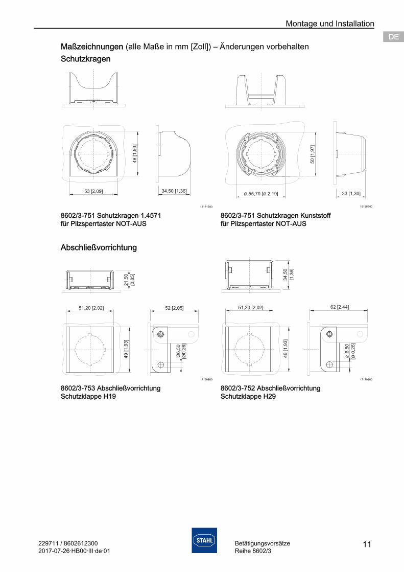
Schutzkragen
17171E00 19188E00
8602/3-751 Schutzkragen 1.4571 für Pilzsperrtaster NOT-AUS
8602/3-751 Schutzkragen Kunststoff für Pilzsperrtaster NOT-AUS
Abschließvorrichtung
17169E00 17170E00
8602/3-753 Abschließvorrichtung Schutzklappe H19
8602/3-752 Abschließvorrichtung Schutzklappe H29
Maßzeichnungen (alle Maße in mm [Zoll]) – Änderungen vorbehalten
49 [1,9
3]
53 [2,09] 34,50 [1,36]
49
[1
,93
]
51,20 [2,02]
Ø6
,50
[Ø0
,26
]
52 [2,05]
[0,8
5]
21
,50
49 [1,9
3]
51,20 [2,02]
Ø6,5
0
[0,2
6]
Ø
62 [2,44]
34,5
0
[1,3
6]

Montage und Installation
12 229711 / 86026123002017-07-26·HB00·III·de·01
BetätigungsvorsätzeReihe 8602/3
DEDEDEDEDEDEDEDEDEDEDEDEDEDEDEDEDEDEDEDEDEDEDEDEDE
Abschließvorrichtung
17165E00 17166E00
8602/3-758 Abschließvorrichtung Schutzklappe H38
8602/3-756 Abschließvorrichtung für betätigten Pilzsperrtaster
Abschließvorrichtung
17168E00 17167E00
8602/3-754 Abschließvorrichtung für betätigten Drucktaster
8602/3-755 Abschließvorrichtung für unbetätigten Drucktaster
Stanzbilder
16360E00 08746E00
Einzelstanzbild Schildträger
Maßzeichnungen (alle Maße in mm [Zoll]) – Änderungen vorbehalten
49 [1,9
3]
51,20 [2,02]
Ø6,5
0[Ø
0,2
6]
71 [2,80]
40,5
0 [1,5
9]
46 [1,81]
Ø Ø6,50 [ 0,26]
48 [1,89]
75 [2,95]
49 [1,9
3]
53,05 [2,09]
55,6
0 [2,1
9]
ØØ
6 [
0,2
4]
[1,03]26,06
53,05 [2,09]
55,6
0 [2,1
9]
ØØ
6 [
0,2
4]
[1,03]26,06
ø 30,5 ±0,10 [ø 1,20 004]±0,
34
,20
0,
+2
0 0,
+0
08
]0
[1,3
5
3,500,+0,10
[1,140,+0,004]0,000
42 [1,65]
40
[1,5
7]
60
[2,3
6]
17
[0,6
7]
51
[2,0
1]
46
[1,8
1]3,50 [0,14]
ø[
1,2
0]
30
,50
ø
42 [1,65] 42 [1,65]
229711 / 86026123002017-07-26·HB00·III·de·01
Montage und Installation
13BetätigungsvorsätzeReihe 8602/3
DEDEDEDEDEDEDEDEDEDEDEDEDEDEDEDEDEDEDEDEDEDEDEDEDE
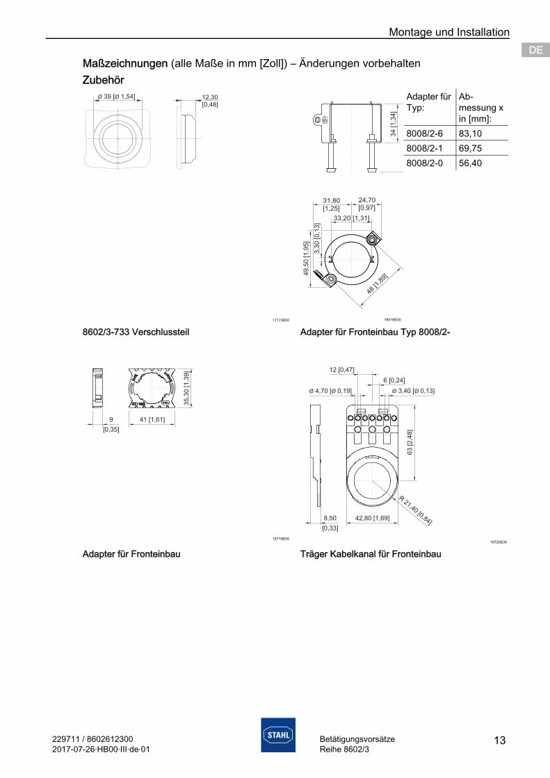
Zubehör
17173E00 19516E00
8602/3-733 Verschlussteil Adapter für Fronteinbau Typ 8008/2-
18719E0018720E00
Adapter für Fronteinbau Träger Kabelkanal für Fronteinbau
Maßzeichnungen (alle Maße in mm [Zoll]) – Änderungen vorbehalten
12,30[0,48]
Ø Ø39 [ 1,54] Adapter für Typ:
Ab-messung x in [mm]:
8008/2-6 83,108008/2-1 69,758008/2-0 56,40
Montage und Installation
14 229711 / 86026123002017-07-26·HB00·III·de·01
BetätigungsvorsätzeReihe 8602/3
DEDEDEDEDEDEDEDEDEDEDEDEDEDEDEDEDEDEDEDEDEDEDEDEDE
7.2 Montage / Demontage, Gebrauchslage
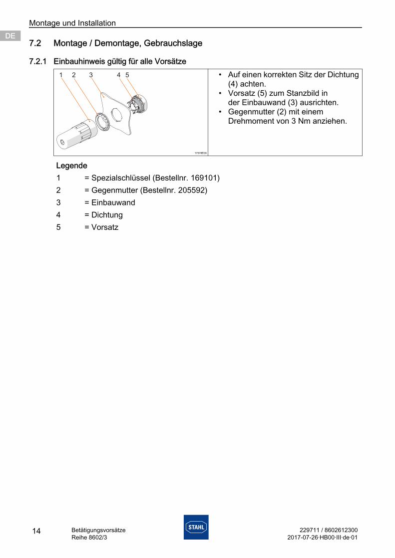
7.2.1 Einbauhinweis gültig für alle Vorsätze
17578E00
• Auf einen korrekten Sitz der Dichtung (4) achten.
• Vorsatz (5) zum Stanzbild in der Einbauwand (3) ausrichten.
• Gegenmutter (2) mit einem Drehmoment von 3 Nm anziehen.
Legende1 = Spezialschlüssel (Bestellnr. 169101)2 = Gegenmutter (Bestellnr. 205592)3 = Einbauwand4 = Dichtung5 = Vorsatz
229711 / 86026123002017-07-26·HB00·III·de·01
Montage und Installation
15BetätigungsvorsätzeReihe 8602/3
DEDEDEDEDEDEDEDEDEDEDEDEDEDEDEDEDEDEDEDEDEDEDEDEDE
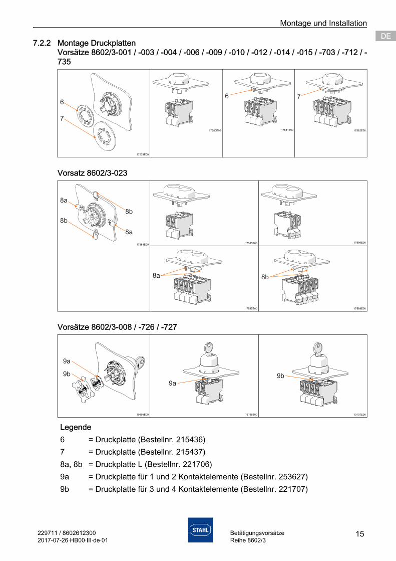
7.2.2 Montage DruckplattenVorsätze 8602/3-001 / -003 / -004 / -006 / -009 / -010 / -012 / -014 / -015 / -703 / -712 / -735
Vorsatz 8602/3-023
Vorsätze 8602/3-008 / -726 / -727
17579E00
17580E00 17581E00 17582E00
17584E00 17585E00 17586E00
17587E00 17588E00
19195E00 19196E00 19197E00
Legende6 = Druckplatte (Bestellnr. 215436)7 = Druckplatte (Bestellnr. 215437)8a, 8b = Druckplatte L (Bestellnr. 221706)9a = Druckplatte für 1 und 2 Kontaktelemente (Bestellnr. 253627)9b = Druckplatte für 3 und 4 Kontaktelemente (Bestellnr. 221707)
Montage und Installation
16 229711 / 86026123002017-07-26·HB00·III·de·01
BetätigungsvorsätzeReihe 8602/3
DEDEDEDEDEDEDEDEDEDEDEDEDEDEDEDEDEDEDEDEDEDEDEDEDE
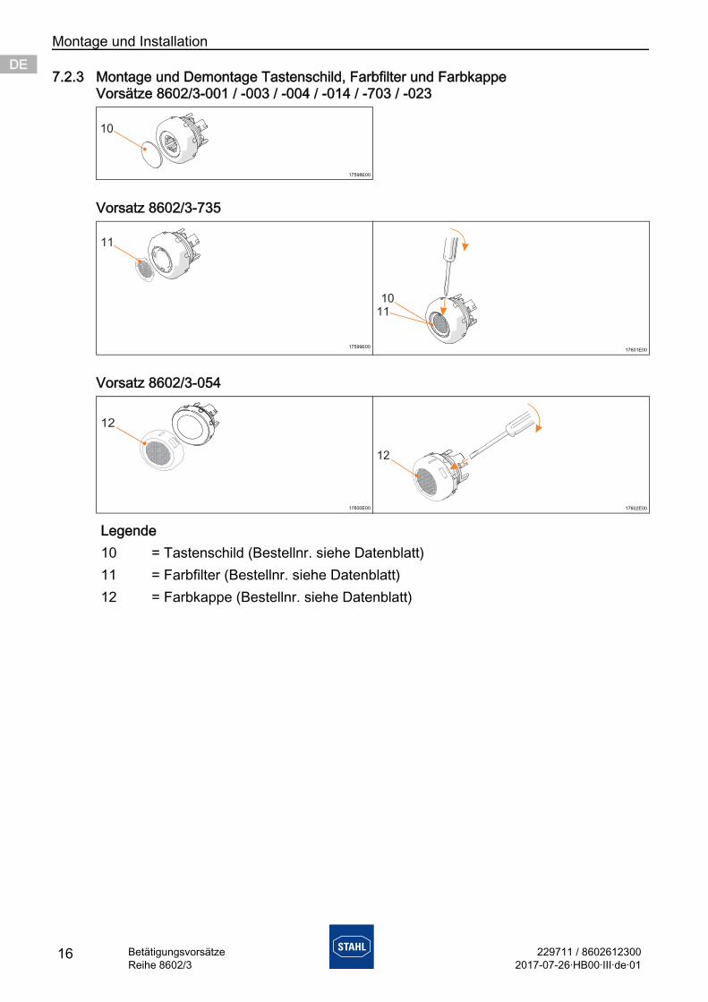
7.2.3 Montage und Demontage Tastenschild, Farbfilter und FarbkappeVorsätze 8602/3-001 / -003 / -004 / -014 / -703 / -023
Vorsatz 8602/3-735
Vorsatz 8602/3-054
17598E00
17599E00 17601E00
17600E00 17602E00
Legende10 = Tastenschild (Bestellnr. siehe Datenblatt)11 = Farbfilter (Bestellnr. siehe Datenblatt)12 = Farbkappe (Bestellnr. siehe Datenblatt)
10
11
1011
12

229711 / 86026123002017-07-26·HB00·III·de·01
Montage und Installation
17BetätigungsvorsätzeReihe 8602/3
DEDEDEDEDEDEDEDEDEDEDEDEDEDEDEDEDEDEDEDEDEDEDEDEDE
7.2.4 Codierung von Drehgriff axial 8602/3-726 / -727 und Schlüsselschalter 8602/3-008rastend rastend
17639E00 17642E00
Stellung 1 oben Stellung 1 obenrastendSchlüssel nicht abziehbar
rastendSchlüssel nicht abziehbar
17641E00 17644E00
Stellung 1 unten Stellung 1 untentastend tastend
17640E00 17643E00
Stellung 2 unten Stellung 2 unten
Montage und Installation
18 229711 / 86026123002017-07-26·HB00·III·de·01
BetätigungsvorsätzeReihe 8602/3
DEDEDEDEDEDEDEDEDEDEDEDEDEDEDEDEDEDEDEDEDEDEDEDEDE
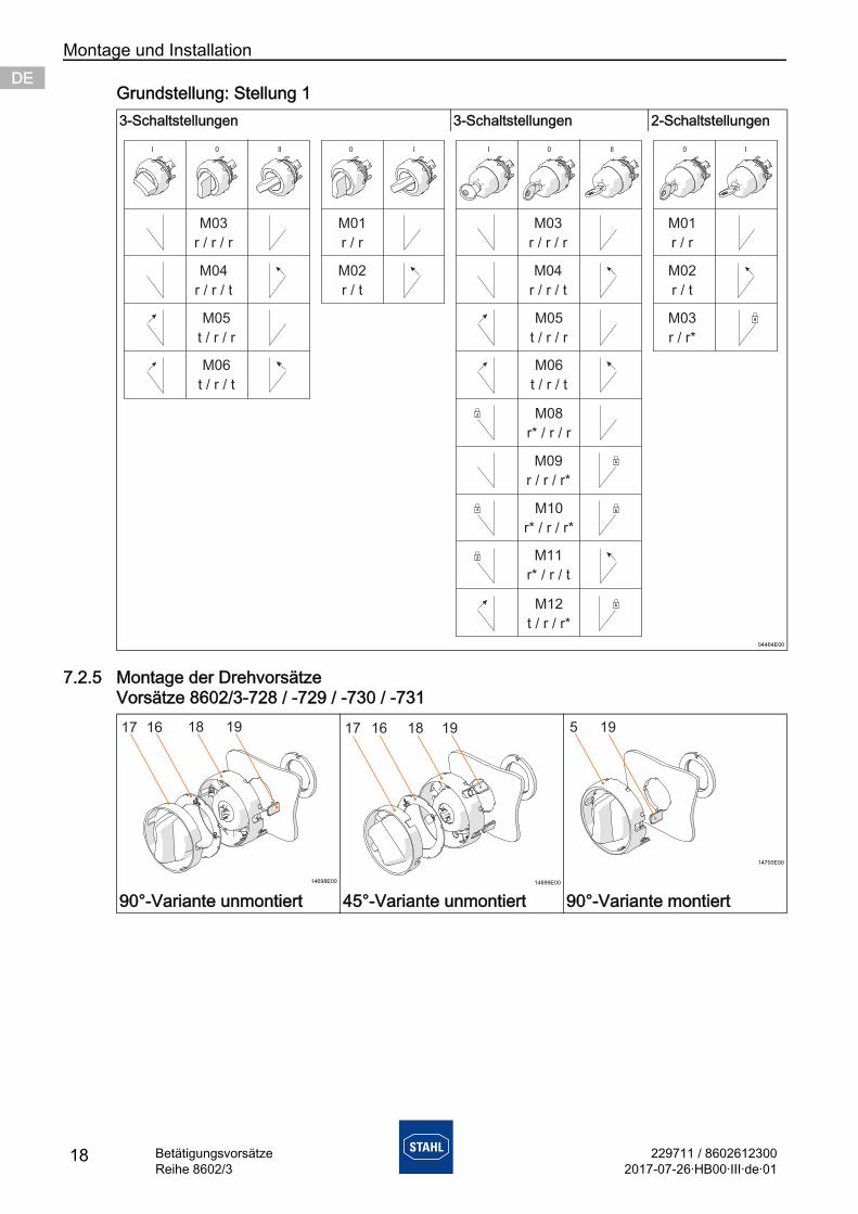
Grundstellung: Stellung 1
7.2.5 Montage der DrehvorsätzeVorsätze 8602/3-728 / -729 / -730 / -731
3-Schaltstellungen 3-Schaltstellungen 2-Schaltstellungen
04464E00
14698E00 14699E00
14700E00
90°-Variante unmontiert 45°-Variante unmontiert 90°-Variante montiert
| 0 || 0 | | 0 || 0 |
M03
r / r / r
M04
r / r / t
M05
t / r / r
M06
t / r / t
M03
r / r / r
M04
r / r / t
M05
t / r / r
M06
t / r / t
M01
r / r
M02
r / t
M01
r / r
M02
r / t
M03
r / r*
M08
r* / r / r
M09
r / r / r*
M10
r* / r / r*
M11
r* / r / t
M12
t / r / r*
229711 / 86026123002017-07-26·HB00·III·de·01
Montage und Installation
19BetätigungsvorsätzeReihe 8602/3
DEDEDEDEDEDEDEDEDEDEDEDEDEDEDEDEDEDEDEDEDEDEDEDEDE
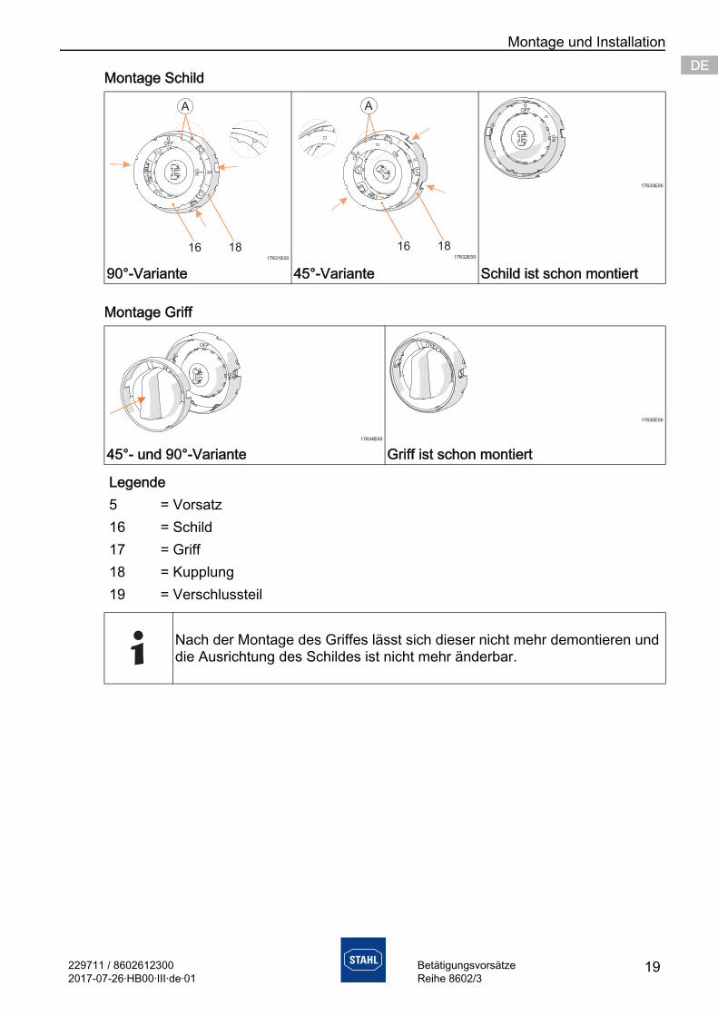
Montage Schild
Montage Griff
17631E00 17632E00
17633E00
90°-Variante 45°-Variante Schild ist schon montiert
17634E00
17635E00
45°- und 90°-Variante Griff ist schon montiert
Legende5 = Vorsatz16 = Schild17 = Griff18 = Kupplung19 = Verschlussteil
Nach der Montage des Griffes lässt sich dieser nicht mehr demontieren und die Ausrichtung des Schildes ist nicht mehr änderbar.
Montage und Installation
20 229711 / 86026123002017-07-26·HB00·III·de·01
BetätigungsvorsätzeReihe 8602/3
DEDEDEDEDEDEDEDEDEDEDEDEDEDEDEDEDEDEDEDEDEDEDEDEDE
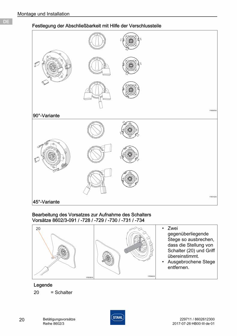
Festlegung der Abschließbarkeit mit Hilfe der Verschlussteile
Bearbeitung des Vorsatzes zur Aufnahme des SchaltersVorsätze 8602/3-091 / -728 / -729 / -730 / -731 / -734
17650E00
90°-Variante
17651E00
45°-Variante
17653E0017659E00
• Zwei gegenüberliegende Stege so ausbrechen, dass die Stellung von Schalter (20) und Griff übereinstimmt.
• Ausgebrochene Stege entfernen.
Legende20 = Schalter
0
OFF
0
OFF
I
ON
0
OFF
0
OFF
ION
0
OFF
0
OFF
229711 / 86026123002017-07-26·HB00·III·de·01
Montage und Installation
21BetätigungsvorsätzeReihe 8602/3
DEDEDEDEDEDEDEDEDEDEDEDEDEDEDEDEDEDEDEDEDEDEDEDEDE
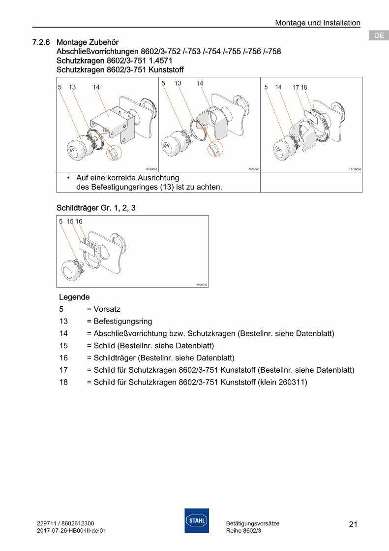
7.2.6 Montage ZubehörAbschließvorrichtungen 8602/3-752 /-753 /-754 /-755 /-756 /-758Schutzkragen 8602/3-751 1.4571Schutzkragen 8602/3-751 Kunststoff
Schildträger Gr. 1, 2, 3
19198E00 17605E00 19199E00
• Auf eine korrekte Ausrichtung des Befestigungsringes (13) ist zu achten.
17606E00
Legende5 = Vorsatz13 = Befestigungsring14 = Abschließvorrichtung bzw. Schutzkragen (Bestellnr. siehe Datenblatt)15 = Schild (Bestellnr. siehe Datenblatt)16 = Schildträger (Bestellnr. siehe Datenblatt)17 = Schild für Schutzkragen 8602/3-751 Kunststoff (Bestellnr. siehe Datenblatt)18 = Schild für Schutzkragen 8602/3-751 Kunststoff (klein 260311)
Montage und Installation
22 229711 / 86026123002017-07-26·HB00·III·de·01
BetätigungsvorsätzeReihe 8602/3
DEDEDEDEDEDEDEDEDEDEDEDEDEDEDEDEDEDEDEDEDEDEDEDEDE
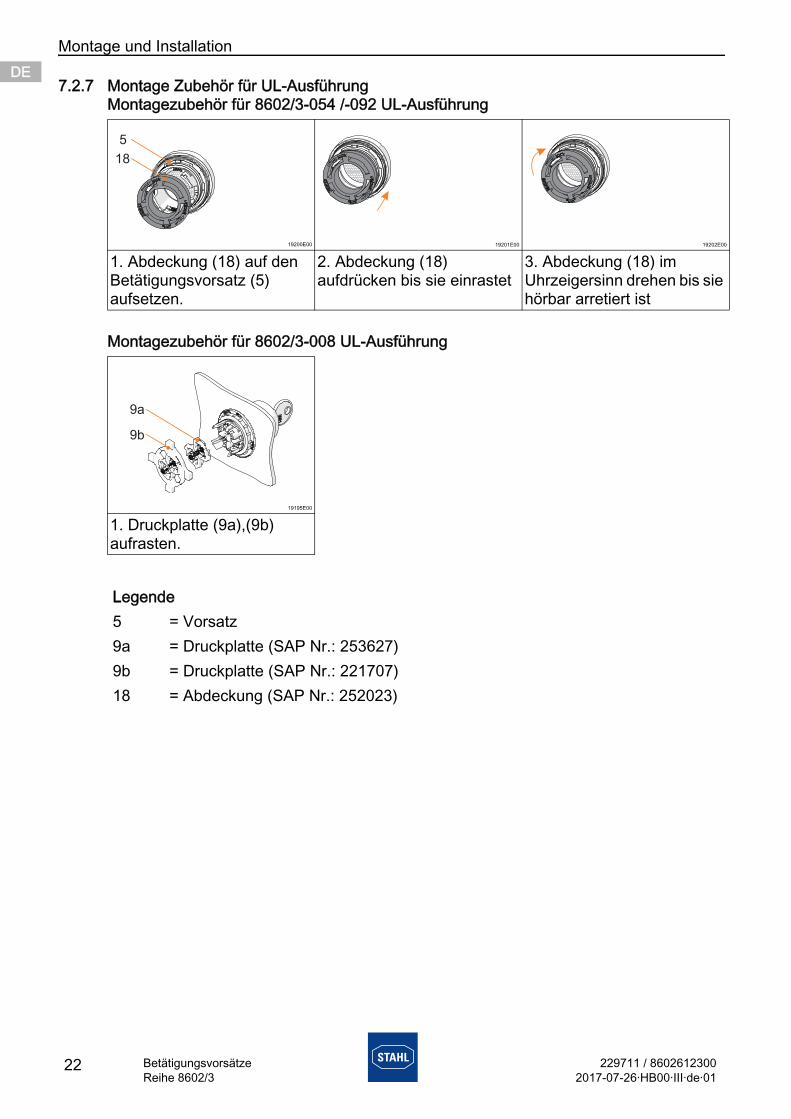
7.2.7 Montage Zubehör für UL-AusführungMontagezubehör für 8602/3-054 /-092 UL-Ausführung
Montagezubehör für 8602/3-008 UL-Ausführung
19200E00 19201E00 19202E00
1. Abdeckung (18) auf den Betätigungsvorsatz (5) aufsetzen.
2. Abdeckung (18) aufdrücken bis sie einrastet
3. Abdeckung (18) im Uhrzeigersinn drehen bis sie hörbar arretiert ist
19195E00
1. Druckplatte (9a),(9b) aufrasten.
Legende5 = Vorsatz9a = Druckplatte (SAP Nr.: 253627)9b = Druckplatte (SAP Nr.: 221707)18 = Abdeckung (SAP Nr.: 252023)
229711 / 86026123002017-07-26·HB00·III·de·01
Montage und Installation
23BetätigungsvorsätzeReihe 8602/3
DEDEDEDEDEDEDEDEDEDEDEDEDEDEDEDEDEDEDEDEDEDEDEDEDE
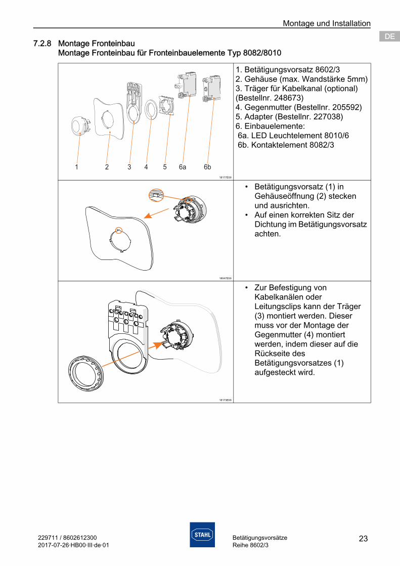
7.2.8 Montage FronteinbauMontage Fronteinbau für Fronteinbauelemente Typ 8082/8010
18177E00
1. Betätigungsvorsatz 8602/32. Gehäuse (max. Wandstärke 5mm)3. Träger für Kabelkanal (optional) (Bestellnr. 248673)4. Gegenmutter (Bestellnr. 205592)5. Adapter (Bestellnr. 227038)6. Einbauelemente: 6a. LED Leuchtelement 8010/6 6b. Kontaktelement 8082/3
18047E00
• Betätigungsvorsatz (1) in Gehäuseöffnung (2) stecken und ausrichten.
• Auf einen korrekten Sitz der Dichtung im Betätigungsvorsatz achten.
18173E00
• Zur Befestigung von Kabelkanälen oder Leitungsclips kann der Träger (3) montiert werden. Dieser muss vor der Montage der Gegenmutter (4) montiert werden, indem dieser auf die Rückseite des Betätigungsvorsatzes (1) aufgesteckt wird.
Montage und Installation
24 229711 / 86026123002017-07-26·HB00·III·de·01
BetätigungsvorsätzeReihe 8602/3
DEDEDEDEDEDEDEDEDEDEDEDEDEDEDEDEDEDEDEDEDEDEDEDEDE
18174E00
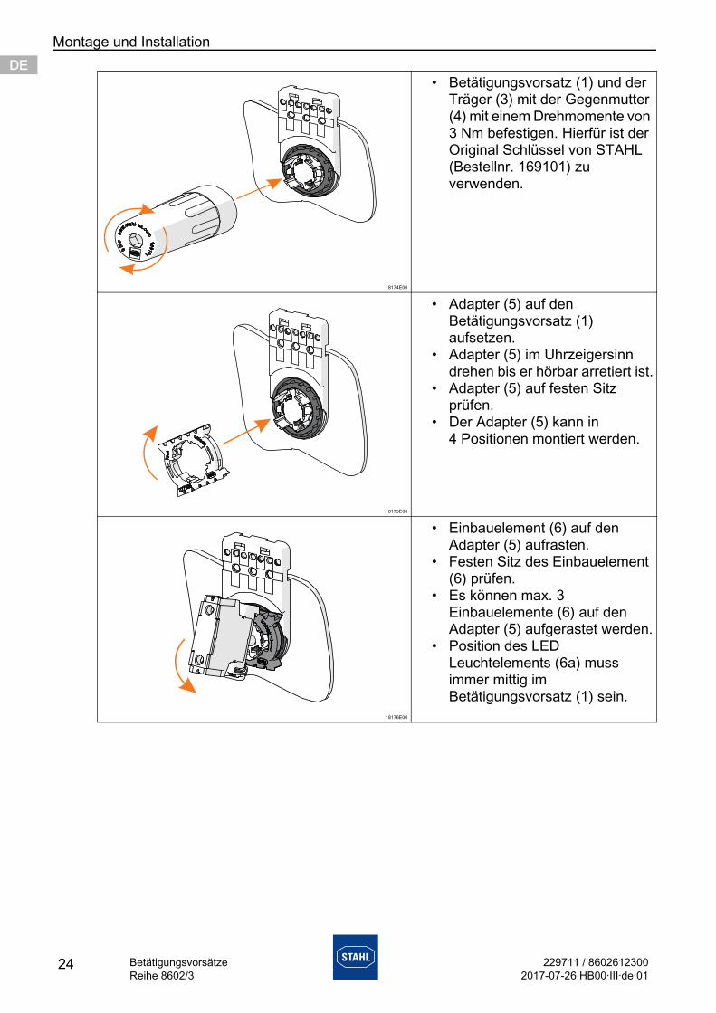
• Betätigungsvorsatz (1) und der Träger (3) mit der Gegenmutter (4) mit einem Drehmomente von 3 Nm befestigen. Hierfür ist der Original Schlüssel von STAHL (Bestellnr. 169101) zu verwenden.
18175E00
• Adapter (5) auf den Betätigungsvorsatz (1) aufsetzen.
• Adapter (5) im Uhrzeigersinn drehen bis er hörbar arretiert ist.
• Adapter (5) auf festen Sitz prüfen.
• Der Adapter (5) kann in 4 Positionen montiert werden.
18176E00
• Einbauelement (6) auf den Adapter (5) aufrasten.
• Festen Sitz des Einbauelement (6) prüfen.
• Es können max. 3 Einbauelemente (6) auf den Adapter (5) aufgerastet werden.
• Position des LED Leuchtelements (6a) muss immer mittig im Betätigungsvorsatz (1) sein.
229711 / 86026123002017-07-26·HB00·III·de·01
Montage und Installation
25BetätigungsvorsätzeReihe 8602/3
DEDEDEDEDEDEDEDEDEDEDEDEDEDEDEDEDEDEDEDEDEDEDEDEDE
18128E00 18129E00
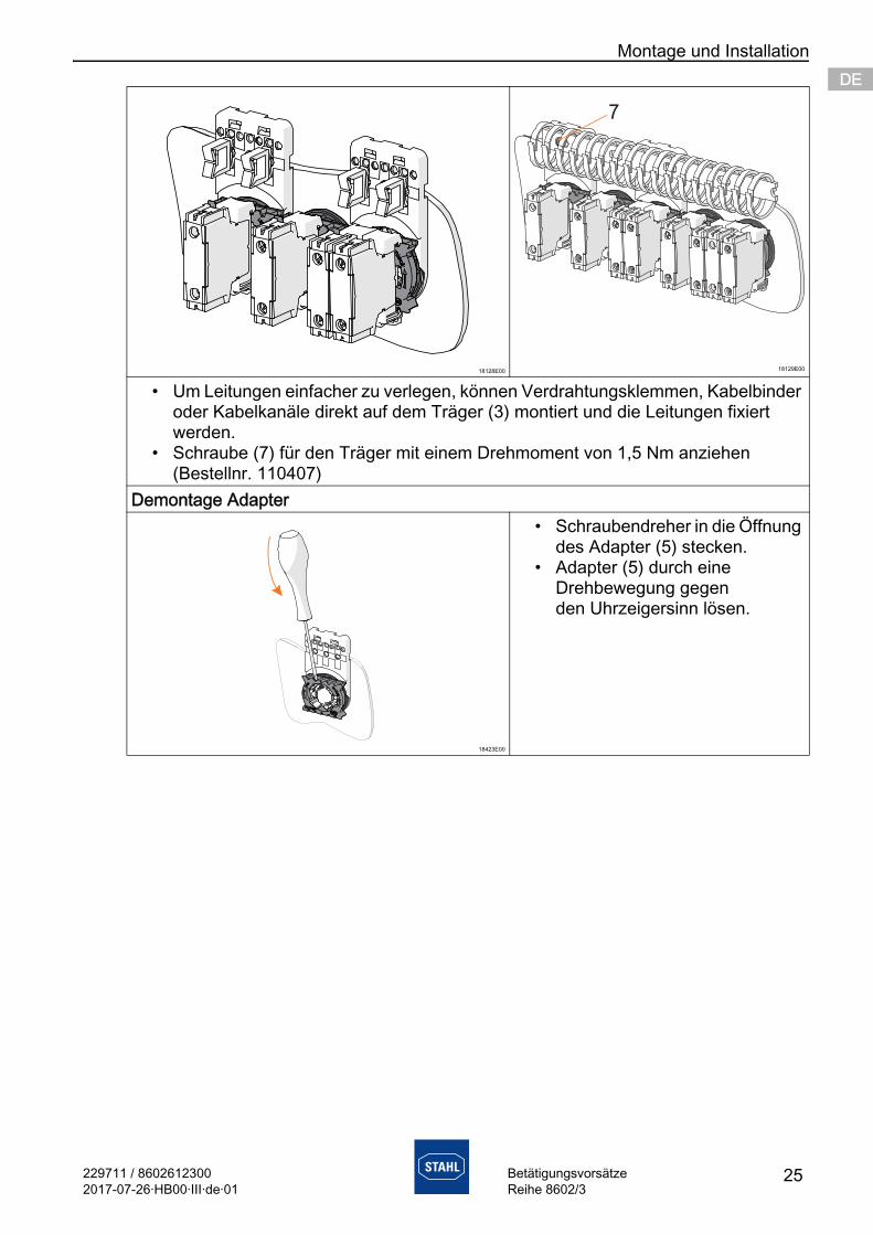
• Um Leitungen einfacher zu verlegen, können Verdrahtungsklemmen, Kabelbinder oder Kabelkanäle direkt auf dem Träger (3) montiert und die Leitungen fixiert werden.
• Schraube (7) für den Träger mit einem Drehmoment von 1,5 Nm anziehen (Bestellnr. 110407)
Demontage Adapter
18423E00
• Schraubendreher in die Öffnung des Adapter (5) stecken.
• Adapter (5) durch eine Drehbewegung gegen den Uhrzeigersinn lösen.
Montage und Installation
26 229711 / 86026123002017-07-26·HB00·III·de·01
BetätigungsvorsätzeReihe 8602/3
DEDEDEDEDEDEDEDEDEDEDEDEDEDEDEDEDEDEDEDEDEDEDEDEDE
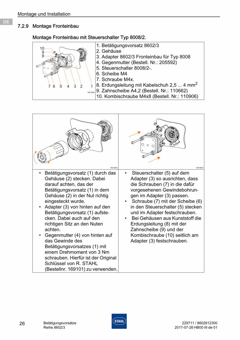
7.2.9 Montage Fronteinbau
Montage Fronteinbau mit Steuerschalter Typ 8008/2.
19613E00
1. Betätigungsvorsatz 8602/32. Gehäuse3. Adapter 8602/3 Fronteinbau für Typ 80084. Gegenmutter (Bestell. Nr.: 205592)5. Steuerschalter 8008/2-.6. Scheibe M47. Schraube M4x.8. Erdungsleitung mit Kabelschuh 2,5 ... 4 mm2
9. Zahnscheibe A4,2 (Bestell. Nr.: 110662)10. Kombischraube M4x8 (Bestell. Nr.: 110906)
19614E00 19615E00
• Betätigungsvorsatz (1) durch das Gehäuse (2) stecken. Dabei darauf achten, das der Betätigungsvorsatz (1) in dem Gehäuse (2) in der Nut richtig eingesteckt wurde.
• Adapter (3) von hinten auf den Betätigungsvorsatz (1) aufste-cken. Dabei auch auf den richtigen Sitz an den Nuten achten.
• Gegenmutter (4) von hinten auf das Gewinde des Betätigungsvorsatzes (1) mit einem Drehmoment von 3 Nm schrauben. Hierfür ist der Original Schlüssel von R. STAHL (Bestellnr. 169101) zu verwenden.
• Steuerschalter (5) auf dem Adapter (3) so ausrichten, dass die Schrauben (7) in die dafür vorgesehenen Gewindebohrun-gen im Adapter (3) passen.
• Schraube (7) mit der Scheibe (6) in den Steuerschalter (5) stecken und im Adapter festschrauben.
• Bei Gehäusen aus Kunststoff die Erdungsleitung (8) mit der Zahnscheibe (9) und der Kombischraube (10) seitlich am Adapter (3) festschrauben.
1098
7 6 5 4 3 2 1
229711 / 86026123002017-07-26·HB00·III·de·01
Inbetriebnahme
27BetätigungsvorsätzeReihe 8602/3
DEDEDEDEDEDEDEDEDEDEDEDEDEDEDEDEDEDEDEDEDEDEDEDEDE
8 Inbetriebnahme
Vor Inbetriebnahme Folgendes sicherstellen:• Montage und Installation kontrollieren.• Vorsätze dürfen keine Schäden aufweisen.• Kontrollieren, ob alle Schrauben und Muttern fest angezogen sind.• Kontrollieren, ob die Dichtung richtig positioniert ist und sauber aufliegt.
9 Instandhaltung, Wartung, Reparatur
9.1 Instandhaltung• Art und Umfang der Prüfungen den entsprechenden nationalen Vorschriften
entnehmen.• Prüfungsintervalle an Betriebsbedingungen anpassen.
Bei der Instandhaltung des Geräts mindestens folgende Punkte prüfen:• Rissbildung und andere sichtbare Schäden am Gerätegehäuse und / oder
Schutzgehäuse, • Einhaltung der zulässigen Temperaturen (gemäß EN 60079),• fester Sitz der Mutter• nur CES-Pflegemittel für Schließzylinder verwenden
9.2 Wartung
9.3 Reparatur
GEFAHRExplosionsgefahr durch fehlerhafte Installation!Nichtbeachten führt zu schweren oder tödlichen Verletzungen.
• Gerät vor der Inbetriebnahme auf korrekte Installation prüfen.• Nationale Bestimmungen einhalten.
VORSICHTStromschlaggefahr bzw. Fehlfunktion des Geräts durch unbefugte Arbeiten!Nichtbeachten kann zu leichten Verletzungen führen!
• Vor Arbeiten am Gerät Spannung abschalten.• Arbeiten am Gerät ausschließlich von dazu autorisierter und
entsprechend geschulter Elektro-Fachkraft ausführen lassen.
Die geltenden nationalen Bestimmungen im Einsatzland beachten.
GEFAHRExplosionsgefahr durch unsachgemäße Reparatur!Nichtbeachten führt zu schweren oder tödlichen Verletzungen.
• Reparaturen an den Geräten ausschließlich durch R. STAHL Schaltgeräte GmbH ausführen lassen.
Entsorgung
28 229711 / 86026123002017-07-26·HB00·III·de·01
BetätigungsvorsätzeReihe 8602/3
DEDEDEDEDEDEDEDEDEDEDEDEDEDEDEDEDEDEDEDEDEDEDEDEDE
9.4 Rücksendung Rücksendung bzw. Verpackung der Geräte nur in Absprache mit
R. STAHL durchführen! Dazu mit der zuständigen Vertretung von R. STAHL Kontakt aufnehmen.
Für die Rücksendung im Reparatur- bzw. Servicefall steht der Kundenservice von R. STAHL zur Verfügung.
Kundenservice persönlich kontaktieren.
oder
Internetseite www.stahl.de aufrufen. Unter "Support" > "RMA Formular" > "RMA-Schein anfordern" wählen. Formular ausfüllen.
Bestätigung erfolgt. Der STAHL-Kundenservice meldet sich bei Ihnen. Nach Rücksprache erhalten Sie einen RMA-Schein.
Gerät zusammen mit dem RMA-Schein in der Verpackung an die R. STAHL Schaltgeräte GmbH senden (Adresse siehe Abschnitt 1.1).
10 Entsorgung• Nationale und lokal gültige Vorschriften und gesetzliche Bestimmungen zur
Entsorgung beachten.• Materialien getrennt dem Recycling zuführen.• Umweltgerechte Entsorgung aller Bauteile gemäß den gesetzlichen Bestimmungen
sicherstellen.
11 Zubehör und Ersatzteile
Rücksendung bzw. Verpackung der Geräte nur nach Kontakt und Absprache mit R. STAHL durchführen!
HINWEISFehlfunktion oder Geräteschaden durch den Einsatz nicht originaler Bauteile.Nichtbeachten kann Sachschaden verursachen!
• Nur Original-Zubehör und Original-Ersatzteile der R. STAHL Schaltgeräte GmbH verwenden.
Zubehör und Ersatzteile, siehe Datenblatt auf Homepage www.stahl-ex.com.
ENENENENENENENENENENENENENENENENENENENENENENENENEN
ManualAdditional languages www.r-stahl.com
EN
Actuators
Series 8602/3
2 ActuatorsSeries 8602/3
ENENENENENENENENENENENENENENENENENENENENENENENENEN
Contents1 General Information ............................................................................................31.1 Manufacturer .......................................................................................................31.2 Information about the manual .............................................................................31.3 Further documents ..............................................................................................31.4 Conformity with standards and regulations .........................................................32 Explanation of the symbols .................................................................................32.1 Symbols used in this manual ..............................................................................32.2 Warning notes .....................................................................................................42.3 Symbols on the device ........................................................................................43 Safety notes ........................................................................................................53.1 Storage of the manual .........................................................................................53.2 Safe use ..............................................................................................................53.3 Modifications and alterations ..............................................................................64 Function and device design ................................................................................64.1 Function ..............................................................................................................65 Technical data .....................................................................................................76 Transport and storage .........................................................................................87 Mounting and installation ....................................................................................87.1 Dimensions / fastening dimensions ....................................................................87.2 Mounting / dismounting, operating position ......................................................148 Commissioning .................................................................................................259 Maintenance, Overhaul, Repair ........................................................................259.1 Maintenance .....................................................................................................259.2 Overhaul ...........................................................................................................259.3 Repair ...............................................................................................................259.4 Returning the device .........................................................................................2610 Disposal ............................................................................................................2611 Accessories and Spare parts ...........................................................................26
229711 / 86026123002017-07-26·HB00·III·en·01
General Information
3ActuatorsSeries 8602/3
ENENENENENENENENENENENENENENENENENENENENENENENENEN
1 General Information
1.1 ManufacturerR. STAHL Schaltgeräte GmbHAm Bahnhof 3074638 Waldenburg Germany
Phone: +49 7942 943-0Fax: +49 7942 943-4333Internet: www.r-stahl.comE-Mail: [email protected]
1.2 Information about the manualID-No.: 229711 / 8602612300Publication Code: 2017-07-26·HB00·III·en·01
1.3 Further documents• Data sheet• Operating instructionsFor documents in further languages, see www.r-stahl.com.
1.4 Conformity with standards and regulationsSee certificates and EU Declaration of Conformity: www.stahl-ex.com.
2 Explanation of the symbols
2.1 Symbols used in this manualSymbol Meaning
Tips and recommendations on the use of the device
Danger due to explosive atmosphere
Danger due to live components
Explanation of the symbols
4 229711 / 86026123002017-07-26·HB00·III·en·01
ActuatorsSeries 8602/3
ENENENENENENENENENENENENENENENENENENENENENENENENEN
2.2 Warning notesWarnings must be observed under all circumstances, in order to minimize the risk due to construction and operation. The warning notes have the following structure:• Signalling word: DANGER, WARNING, CAUTION, NOTICE• Type and source of danger/damage• Consequences of danger• Taking countermeasures to avoid the danger or damage
2.3 Symbols on the device
DANGERDanger to personsNon-compliance with the instruction results in severe or fatal injuries to persons.
WARNINGDanger to personsNon-compliance with the instruction can result in severe or fatal injuries to persons.
CAUTIONDanger to personsNon-compliance with the instruction can result in light injuries to persons.
NOTICEAvoiding material damageNon-compliance with the instruction can result in material damage to the device and / or its environment.
Symbol Meaning
16338E00
Notified body for quality control.
02198E00
Device certified for hazardous areas in accordance with the marking.
229711 / 86026123002017-07-26·HB00·III·en·01
Safety notes
5ActuatorsSeries 8602/3
ENENENENENENENENENENENENENENENENENENENENENENENENEN
3 Safety notes
3.1 Storage of the manual• Read the manual carefully.• Store the manual at the mounting location of the device.• Observe applicable documents and operating instructions of the devices to be
connected.
3.2 Safe useBefore assembly• Read and observe the safety notes in this manual.• Ensure that the contents of this manual are fully understood by the personnel in
charge.• Use the device in accordance with its intended and approved purpose only.• Always consult with R. STAHL Schaltgeräte GmbH if using the device under operating
conditions not covered by the technical data.• Make sure that the device is not damaged.• We are not liable for damage caused by incorrect or unauthorised use of the device or
by non-compliance with this manual.
For assembly and installation• Observe national assembly and installation regulations (e.g. IEC/EN 60079-14).• Observe national safety and accident prevention regulations.• During installation and operation, observe the information (characteristic values and
rated operating conditions) on the type plates and data plates and information signs located on the device.
• Before installation, make sure that the device is not damaged.
• Do not use coated metal protective collars in areas where high charge-generating processes, machine friction and separation processes, electron spraying (e.g. around electrostatic coating systems) and pneumatically conveyed dust occur.
Maintenance, repair, commissioning• Before commissioning, make sure that the device is not damaged.• Work on the device, such as installation, maintenance, overhaul, repair, may only
be carried out by appropriately authorised and trained personnel.• Perform only maintenance work or repair described in this manual.
Function and device design
6 229711 / 86026123002017-07-26·HB00·III·en·01
ActuatorsSeries 8602/3
ENENENENENENENENENENENENENENENENENENENENENENENENEN
3.3 Modifications and alterations
4 Function and device design
4.1 FunctionApplication rangeThe actuators 8602/3 are designed for installation in enclosure walls and enclosure covers of electrical equipment or of panels of the type of protection Increased safety "e" and Protection by enclosure "tb". The components are approved for use in hazardous areas of Zones 1, 2, 21 and 22.
DANGERExplosion hazard due to modifications and alterations to the device! Non-compliance results in severe or fatal injuries.
• Do not modify or alter the device.
No liability or warranty for damage resulting from modifications and alterations.
DANGERExplosion hazard due to improper use!Non-compliance results in severe or fatal injuries.
• The device may only be used according to the operating conditions described in this manual.
• Use the device only for the intended purpose specified in this manual.
229711 / 86026123002017-07-26·HB00·III·en·01
Technical data
7ActuatorsSeries 8602/3
ENENENENENENENENENENENENENENENENENENENENENENENENEN
5 Technical data
For further technical data, see www.r-stahl.com.
Explosion ProtectionGlobal (IECEx)
Gas and dust IECEx PTB 13.0047UEx eb IIC GbEx tb IIIC Db
Europe (ATEX)Gas and dust PTB 13 ATEX 1019 U
E II 2 G Ex eb IIC GbE II 2 D Ex tb IIIC Db
Certifications and certificatesCertificates IECEx, ATEX
Technical DataAmbient conditions
Operating temperature
Maximum relative humidity
max. 50% (+40 °C)max. 90% (+20 °C)
Storage temperature
Actuators with silicone seals have coloured labels on the bottom.Use at the height of < 2,000 m
Mechanical dataMaterial polyamideDegree of protection IP66 (IP68 on request) Service life ) 100,000Degree of pollution 3Impact strength 7 J (EN 60079-0)
min. IK08 (EN 62208)4 J (EN 60079-0: illuminated pushbutton and indicator lamp bezel)
Dimensions see dimensional drawingsTightening torque of the locknut
3 Nm
Silicone-free (NBR) -20 to +60 °CSilicone: -60 to +70 °C
Silicone-free (NBR): -25 to +60 °CSilicone: -60 to +70 °C
Transport and storage
8 229711 / 86026123002017-07-26·HB00·III·en·01
ActuatorsSeries 8602/3
ENENENENENENENENENENENENENENENENENENENENENENENENEN
6 Transport and storage• Transport and store the device only in the original packaging.• Store the device in a dry place (no condensation) and vibration-free.• Do not drop the device.
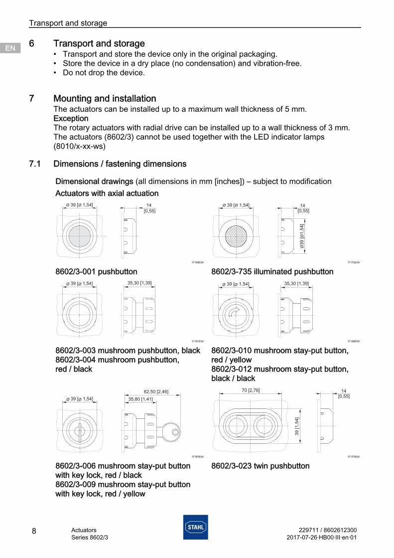
7 Mounting and installationThe actuators can be installed up to a maximum wall thickness of 5 mm.ExceptionThe rotary actuators with radial drive can be installed up to a wall thickness of 3 mm.The actuators (8602/3) cannot be used together with the LED indicator lamps (8010/x-xx-ws)
7.1 Dimensions / fastening dimensions
Dimensional drawings (all dimensions in mm [inches]) – subject to modificationActuators with axial actuation
17188E00 17172E00
8602/3-001 pushbutton 8602/3-735 illuminated pushbutton
17181E00 17186E00
8602/3-003 mushroom pushbutton, black8602/3-004 mushroom pushbutton, red / black
8602/3-010 mushroom stay-put button, red / yellow8602/3-012 mushroom stay-put button, black / black
17187E00 17177E00
8602/3-006 mushroom stay-put button with key lock, red / black8602/3-009 mushroom stay-put button with key lock, red / yellow
8602/3-023 twin pushbutton
Ø Ø39 [ 1,54] 14
[0,55]14
ØØ
39 [
1,5
4]
[0,55]
Ø Ø39 [ 1,54]
35,30 [1,39]Ø Ø39 [ 1,54] 35,30 [1,39]Ø Ø39 [ 1,54]
35,80 [1,41]Ø Ø39 [ 1,54]
62,50 [2,46]
39
[1
,54
]
70 [2,76] 14[0,55]
229711 / 86026123002017-07-26·HB00·III·en·01
Mounting and installation
9ActuatorsSeries 8602/3
ENENENENENENENENENENENENENENENENENENENENENENENENEN
17180E00 17349E00
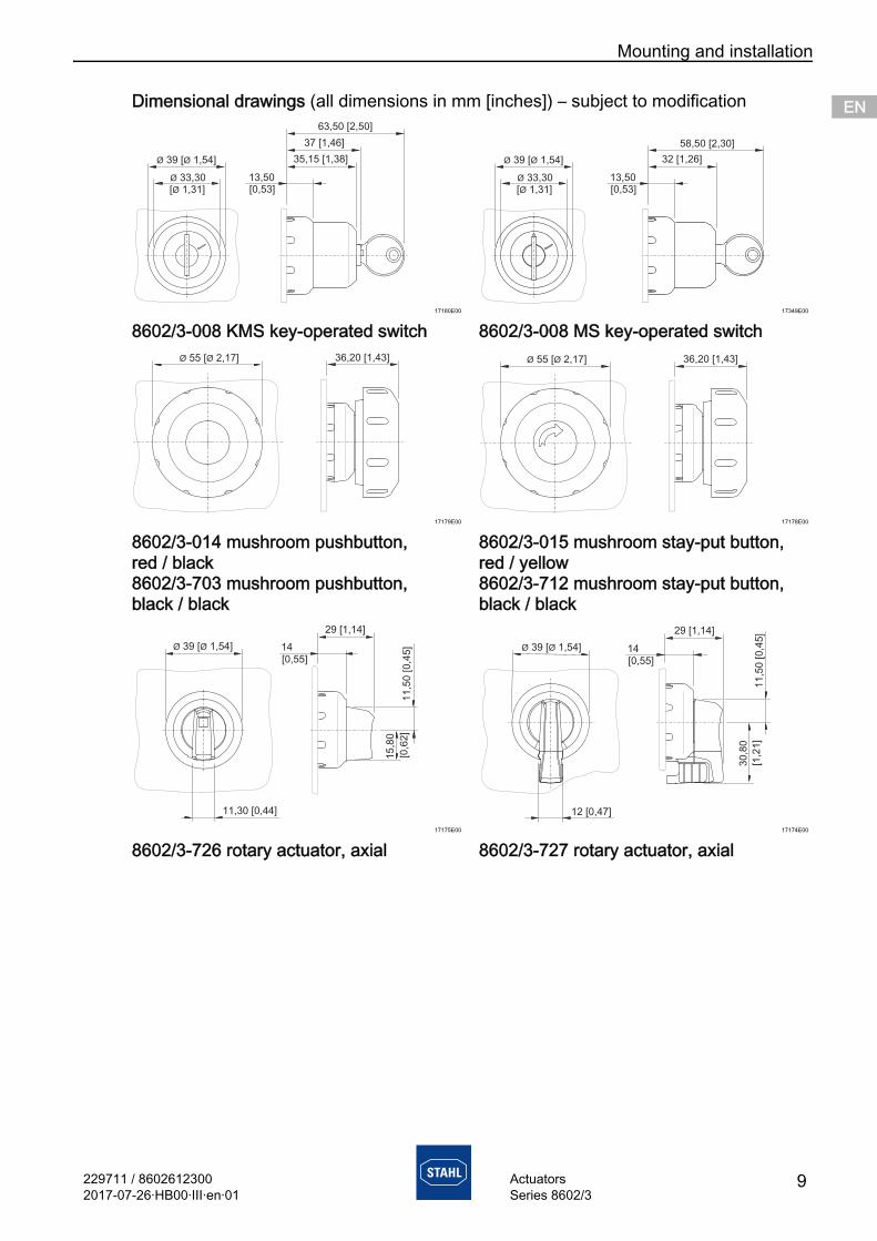
8602/3-008 KMS key-operated switch 8602/3-008 MS key-operated switch
17179E00 17178E00
8602/3-014 mushroom pushbutton, red / black8602/3-703 mushroom pushbutton, black / black
8602/3-015 mushroom stay-put button, red / yellow8602/3-712 mushroom stay-put button, black / black
17175E00 17174E00
8602/3-726 rotary actuator, axial 8602/3-727 rotary actuator, axial
Dimensional drawings (all dimensions in mm [inches]) – subject to modification
Ø Ø39 [ 1,54]
[ 1,31]Ø
Ø 33,30 13,50[0,53]
35,15 [1,38]
37 [1,46]
63,50 [2,50]
Ø Ø39 [ 1,54]
[ 1,31]Ø
Ø 33,30 13,50[0,53]
32 [1,26]
58,50 [2,30]
36,20 [1,43]Ø Ø55 [ 2,17] 36,20 [1,43]Ø Ø55 [ 2,17]
Ø Ø39 [ 1,54]
11,30 [0,44]
14
[0,5 ]5
29 [1,14]
15,8
0
[0,6
2]
11,5
0 [0,4
5] Ø Ø39 [ 1,54]
12 [0,47]
30,8
0
11,5
0 [0,4
5]
14
[0,5 ]5
29 [1,14]
[1,2
1]
Mounting and installation
10 229711 / 86026123002017-07-26·HB00·III·en·01
ActuatorsSeries 8602/3
ENENENENENENENENENENENENENENENENENENENENENENENENEN
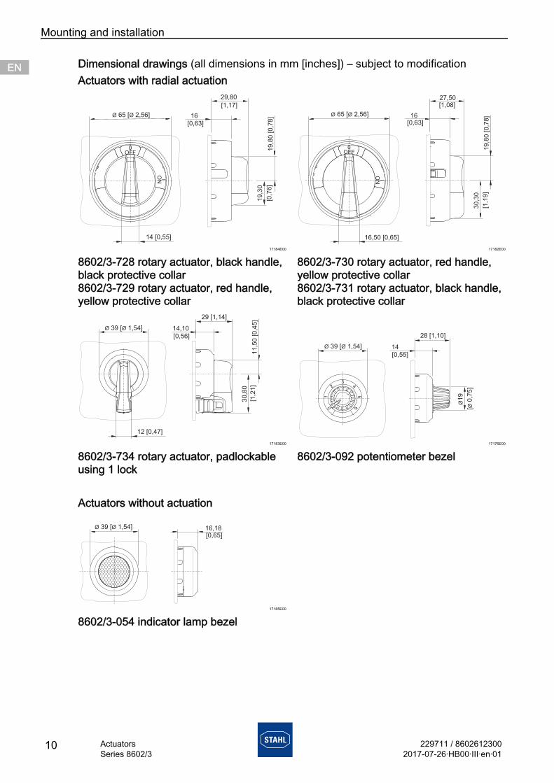
Actuators with radial actuation
17184E00 17182E00
8602/3-728 rotary actuator, black handle, black protective collar8602/3-729 rotary actuator, red handle, yellow protective collar
8602/3-730 rotary actuator, red handle, yellow protective collar8602/3-731 rotary actuator, black handle, black protective collar
17183E00 17176E00
8602/3-734 rotary actuator, padlockable using 1 lock
8602/3-092 potentiometer bezel
Actuators without actuation
17185E00
8602/3-054 indicator lamp bezel
Dimensional drawings (all dimensions in mm [inches]) – subject to modification
0OFF
I
ON
Ø Ø65 [ 2,56] 16
29,80
[0,63]
19
,30
[0,7
6]
19
,80
[0
,78
]
14 [0,55]
[1,17]
0OFF
16,50 [0,65]
I
ON
Ø Ø65 [ 2,56]
30,3
0
19,8
0 [0,7
8]16
[0,63]
27,50[1,08]
[1,1
9]
30,8
0
14,10
[0,56]
29 [1,14]
11,5
0 [0,4
5]
Ø Ø39 [ 1,54]
[1,2
1]
12 [0,47]
12
6
3
45
0
Ø Ø39 [ 1,54]
Ø19
[0,7
5]
Ø
14
[0,5 ]5
28 [1,10]
16,18[0,65]
39 [ 1,54]Ø Ø
229711 / 86026123002017-07-26·HB00·III·en·01
Mounting and installation
11ActuatorsSeries 8602/3
ENENENENENENENENENENENENENENENENENENENENENENENENEN
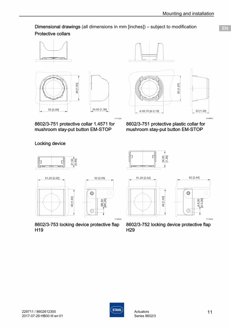
Protective collars
17171E00 19188E00
8602/3-751 protective collar 1.4571 for mushroom stay-put button EM-STOP
8602/3-751 protective plastic collar for mushroom stay-put button EM-STOP
Locking device
17169E00 17170E00
8602/3-753 locking device protective flap H19
8602/3-752 locking device protective flap H29
Dimensional drawings (all dimensions in mm [inches]) – subject to modification
49 [1,9
3]
53 [2,09] 34,50 [1,36]
49
[1
,93
]
51,20 [2,02]
Ø6
,50
[Ø0
,26
]
52 [2,05]
[0,8
5]
21
,50
49 [1,9
3]
51,20 [2,02]
Ø6,5
0
[0,2
6]
Ø
62 [2,44]
34,5
0
[1,3
6]
Mounting and installation
12 229711 / 86026123002017-07-26·HB00·III·en·01
ActuatorsSeries 8602/3
ENENENENENENENENENENENENENENENENENENENENENENENENEN
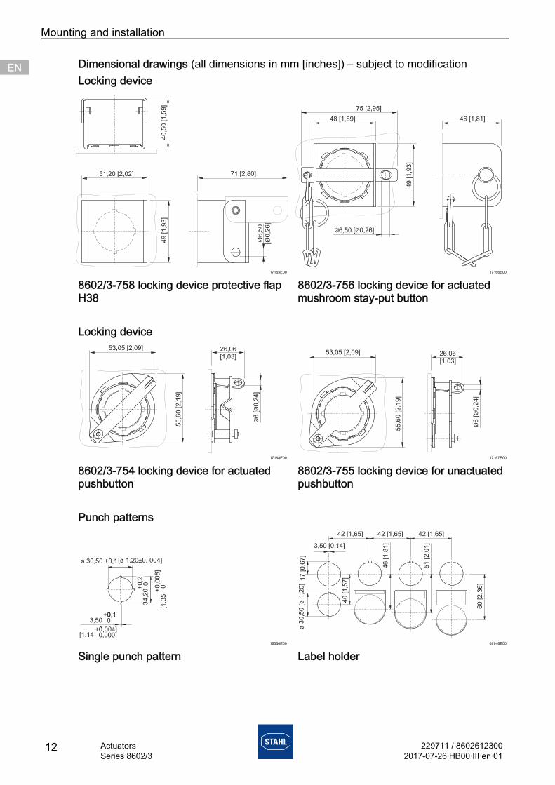
Locking device
17165E00 17166E00
8602/3-758 locking device protective flap H38
8602/3-756 locking device for actuated mushroom stay-put button
Locking device
17168E00 17167E00
8602/3-754 locking device for actuated pushbutton
8602/3-755 locking device for unactuated pushbutton
Punch patterns
16360E00 08746E00
Single punch pattern Label holder
Dimensional drawings (all dimensions in mm [inches]) – subject to modification
49 [1,9
3]
51,20 [2,02]
Ø6,5
0[Ø
0,2
6]
71 [2,80]
40,5
0 [1,5
9]
46 [1,81]
Ø Ø6,50 [ 0,26]
48 [1,89]
75 [2,95]
49 [1,9
3]
53,05 [2,09]
55,6
0 [2,1
9]
ØØ
6 [
0,2
4]
[1,03]26,06
53,05 [2,09]
55,6
0 [2,1
9]
ØØ
6 [
0,2
4]
[1,03]26,06
ø 30,5 ±0,10 [ø 1,20 004]±0,
34
,20
0,
+2
0 0,
+0
08
]0
[1,3
5
3,500,+0,10
[1,140,+0,004]0,000
42 [1,65]
40
[1,5
7]
60
[2,3
6]
17
[0,6
7]
51
[2,0
1]
46
[1,8
1]3,50 [0,14]
ø[
1,2
0]
30
,50
ø
42 [1,65] 42 [1,65]
229711 / 86026123002017-07-26·HB00·III·en·01
Mounting and installation
13ActuatorsSeries 8602/3
ENENENENENENENENENENENENENENENENENENENENENENENENEN
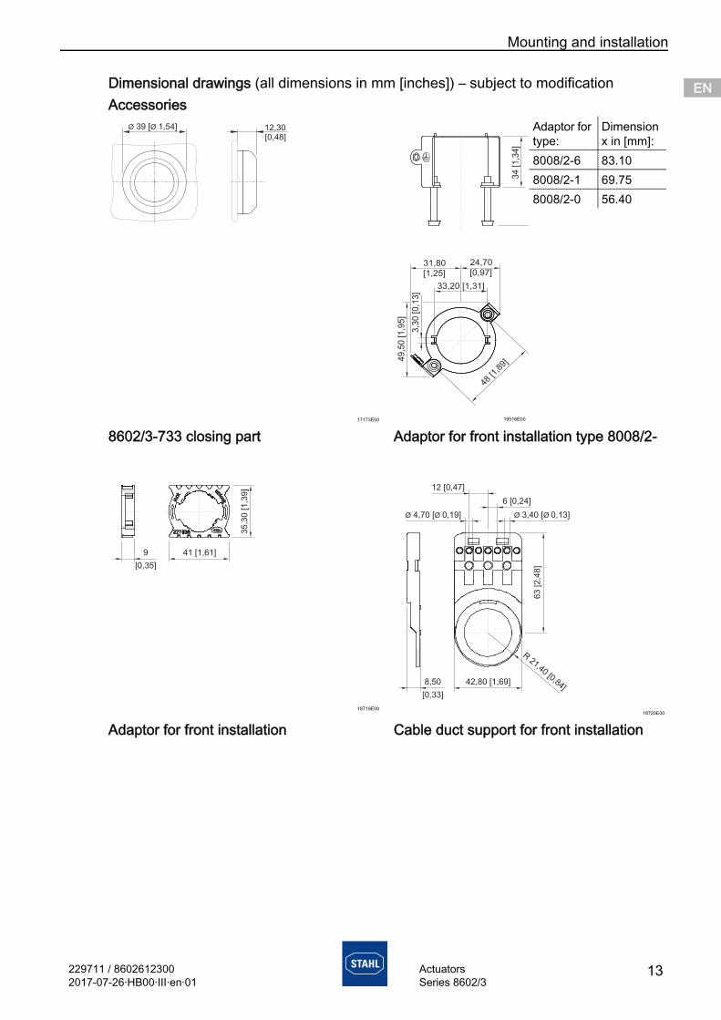
Accessories
17173E00 19516E00
8602/3-733 closing part Adaptor for front installation type 8008/2-
18719E0018720E00
Adaptor for front installation Cable duct support for front installation
Dimensional drawings (all dimensions in mm [inches]) – subject to modification
12,30[0,48]
Ø Ø39 [ 1,54] Adaptor for type:
Dimension x in [mm]:
8008/2-6 83.108008/2-1 69.758008/2-0 56.40
Mounting and installation
14 229711 / 86026123002017-07-26·HB00·III·en·01
ActuatorsSeries 8602/3
ENENENENENENENENENENENENENENENENENENENENENENENENEN
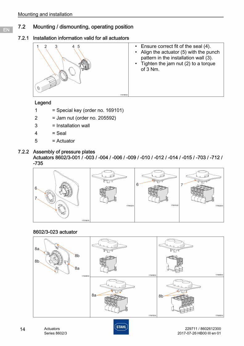
7.2 Mounting / dismounting, operating position
7.2.1 Installation information valid for all actuators
7.2.2 Assembly of pressure platesActuators 8602/3-001 / -003 / -004 / -006 / -009 / -010 / -012 / -014 / -015 / -703 / -712 / -735
8602/3-023 actuator
17578E00
• Ensure correct fit of the seal (4).• Align the actuator (5) with the punch
pattern in the installation wall (3).• Tighten the jam nut (2) to a torque
of 3 Nm.
Legend1 = Special key (order no. 169101)2 = Jam nut (order no. 205592)3 = Installation wall4 = Seal5 = Actuator
17579E00
17580E00 17581E00 17582E00
17584E00 17585E00 17586E00
17587E00 17588E00
229711 / 86026123002017-07-26·HB00·III·en·01
Mounting and installation
15ActuatorsSeries 8602/3
ENENENENENENENENENENENENENENENENENENENENENENENENEN
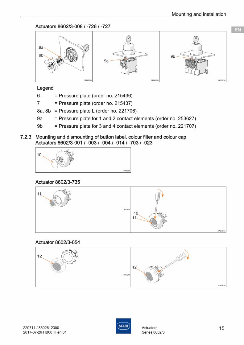
Actuators 8602/3-008 / -726 / -727
7.2.3 Mounting and dismounting of button label, colour filter and colour capActuators 8602/3-001 / -003 / -004 / -014 / -703 / -023
Actuator 8602/3-735
Actuator 8602/3-054
19195E00 19196E00 19197E00
Legend6 = Pressure plate (order no. 215436)7 = Pressure plate (order no. 215437)8a, 8b = Pressure plate L (order no. 221706)9a = Pressure plate for 1 and 2 contact elements (order no. 253627)9b = Pressure plate for 3 and 4 contact elements (order no. 221707)
17598E00
17599E00
17601E00
17600E00
17602E00
10
11
1011
12
Mounting and installation
16 229711 / 86026123002017-07-26·HB00·III·en·01
ActuatorsSeries 8602/3
ENENENENENENENENENENENENENENENENENENENENENENENENEN
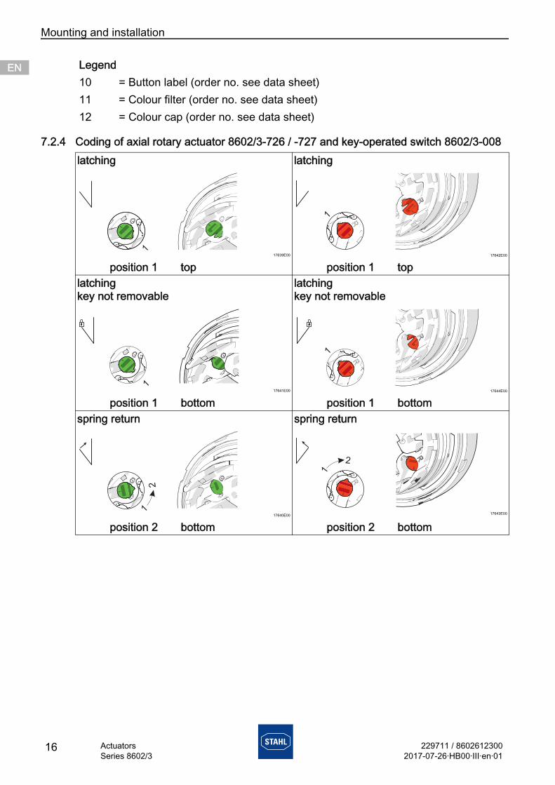
7.2.4 Coding of axial rotary actuator 8602/3-726 / -727 and key-operated switch 8602/3-008
Legend10 = Button label (order no. see data sheet)11 = Colour filter (order no. see data sheet)12 = Colour cap (order no. see data sheet)
latching latching
17639E00 17642E00
position 1 top position 1 toplatchingkey not removable
latchingkey not removable
17641E00 17644E00
position 1 bottom position 1 bottomspring return spring return
17640E00 17643E00
position 2 bottom position 2 bottom
229711 / 86026123002017-07-26·HB00·III·en·01
Mounting and installation
17ActuatorsSeries 8602/3
ENENENENENENENENENENENENENENENENENENENENENENENENEN
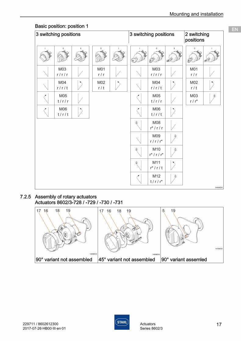
Basic position: position 1
7.2.5 Assembly of rotary actuatorsActuators 8602/3-728 / -729 / -730 / -731
3 switching positions 3 switching positions 2 switching positions
04464E00
14698E00 14699E00
14700E00
90° variant not assembled 45° variant not assembled 90° variant assemled
| 0 || 0 | | 0 || 0 |
M03
r / r / r
M04
r / r / t
M05
t / r / r
M06
t / r / t
M03
r / r / r
M04
r / r / t
M05
t / r / r
M06
t / r / t
M01
r / r
M02
r / t
M01
r / r
M02
r / t
M03
r / r*
M08
r* / r / r
M09
r / r / r*
M10
r* / r / r*
M11
r* / r / t
M12
t / r / r*
Mounting and installation
18 229711 / 86026123002017-07-26·HB00·III·en·01
ActuatorsSeries 8602/3
ENENENENENENENENENENENENENENENENENENENENENENENENEN
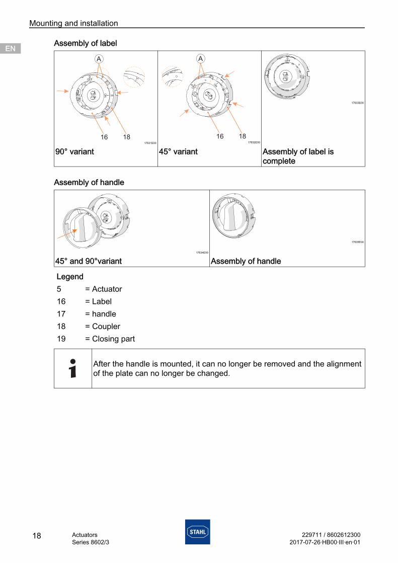
Assembly of label
Assembly of handle
17631E00 17632E00
17633E00
90° variant 45° variant Assembly of label is complete
17634E00
17635E00
45° and 90°variant Assembly of handle
Legend5 = Actuator16 = Label17 = handle18 = Coupler19 = Closing part
After the handle is mounted, it can no longer be removed and the alignment of the plate can no longer be changed.
229711 / 86026123002017-07-26·HB00·III·en·01
Mounting and installation
19ActuatorsSeries 8602/3
ENENENENENENENENENENENENENENENENENENENENENENENENEN
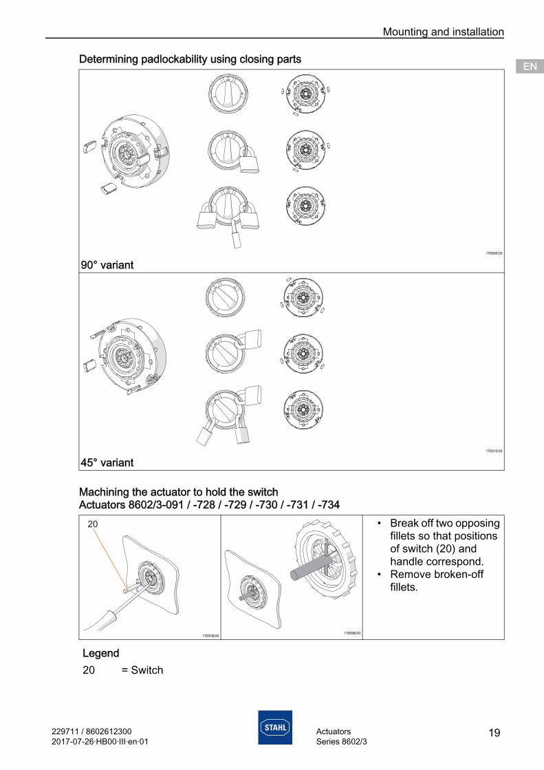
Determining padlockability using closing parts
Machining the actuator to hold the switchActuators 8602/3-091 / -728 / -729 / -730 / -731 / -734
17650E00
90° variant
17651E00
45° variant
17653E0017659E00
• Break off two opposing fillets so that positions of switch (20) and handle correspond.
• Remove broken-off fillets.
Legend20 = Switch
0
OFF
0
OFF
I
ON
0
OFF
0
OFF
ION
0
OFF
0
OFF
Mounting and installation
20 229711 / 86026123002017-07-26·HB00·III·en·01
ActuatorsSeries 8602/3
ENENENENENENENENENENENENENENENENENENENENENENENENEN
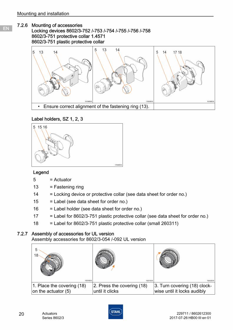
7.2.6 Mounting of accessoriesLocking devices 8602/3-752 /-753 /-754 /-755 /-756 /-7588602/3-751 protective collar 1.45718602/3-751 plastic protective collar
Label holders, SZ 1, 2, 3
7.2.7 Assembly of accessories for UL versionAssembly accessories for 8602/3-054 /-092 UL version
19198E00 17605E00 19199E00
• Ensure correct alignment of the fastening ring (13).
17606E00
Legend5 = Actuator13 = Fastening ring14 = Locking device or protective collar (see data sheet for order no.)15 = Label (see data sheet for order no.)16 = Label holder (see data sheet for order no.)17 = Label for 8602/3-751 plastic protective collar (see data sheet for order no.)18 = Label for 8602/3-751 plastic protective collar (small 260311)
19200E00 19201E00 19202E00
1. Place the covering (18) on the actuator (5)
2. Press the covering (18) until it clicks
3. Turn covering (18) clock-wise until it locks audibly
229711 / 86026123002017-07-26·HB00·III·en·01
Mounting and installation
21ActuatorsSeries 8602/3
ENENENENENENENENENENENENENENENENENENENENENENENENEN
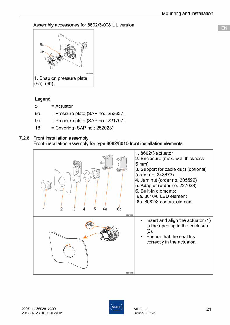
Assembly accessories for 8602/3-008 UL version
7.2.8 Front installation assemblyFront installation assembly for type 8082/8010 front installation elements
19195E00
1. Snap on pressure plate (9a), (9b).
Legend5 = Actuator9a = Pressure plate (SAP no.: 253627)9b = Pressure plate (SAP no.: 221707)18 = Covering (SAP no.: 252023)
18177E00
1. 8602/3 actuator2. Enclosure (max. wall thickness 5 mm)3. Support for cable duct (optional) (order no. 248673)4. Jam nut (order no. 205592)5. Adaptor (order no. 227038)6. Built-in elements: 6a. 8010/6 LED element 6b. 8082/3 contact element
18047E00
• Insert and align the actuator (1) in the opening in the enclosure (2).
• Ensure that the seal fits correctly in the actuator.
Mounting and installation
22 229711 / 86026123002017-07-26·HB00·III·en·01
ActuatorsSeries 8602/3
ENENENENENENENENENENENENENENENENENENENENENENENENEN
18173E00
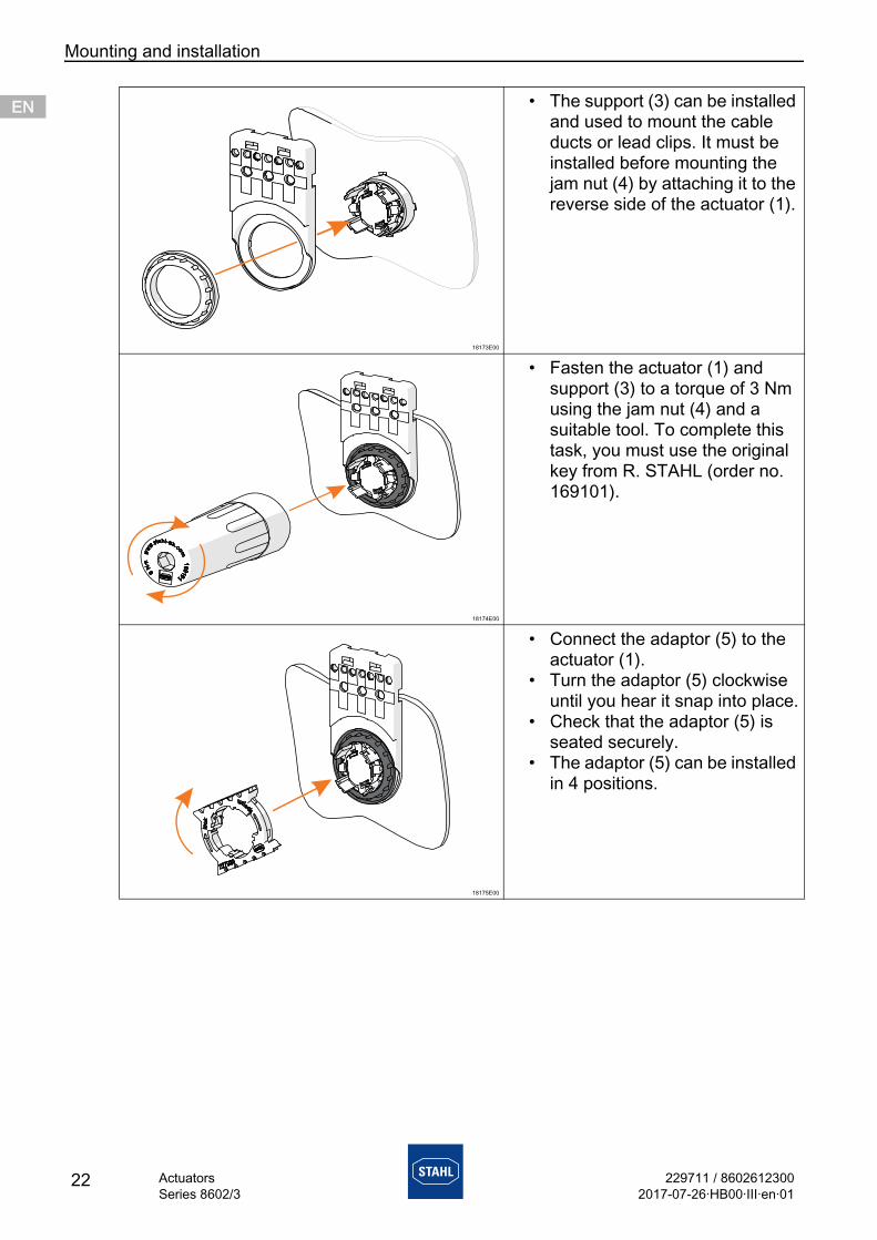
• The support (3) can be installed and used to mount the cable ducts or lead clips. It must be installed before mounting the jam nut (4) by attaching it to the reverse side of the actuator (1).
18174E00
• Fasten the actuator (1) and support (3) to a torque of 3 Nm using the jam nut (4) and a suitable tool. To complete this task, you must use the original key from R. STAHL (order no. 169101).
18175E00
• Connect the adaptor (5) to the actuator (1).
• Turn the adaptor (5) clockwise until you hear it snap into place.
• Check that the adaptor (5) is seated securely.
• The adaptor (5) can be installed in 4 positions.
229711 / 86026123002017-07-26·HB00·III·en·01
Mounting and installation
23ActuatorsSeries 8602/3
ENENENENENENENENENENENENENENENENENENENENENENENENEN
18176E00
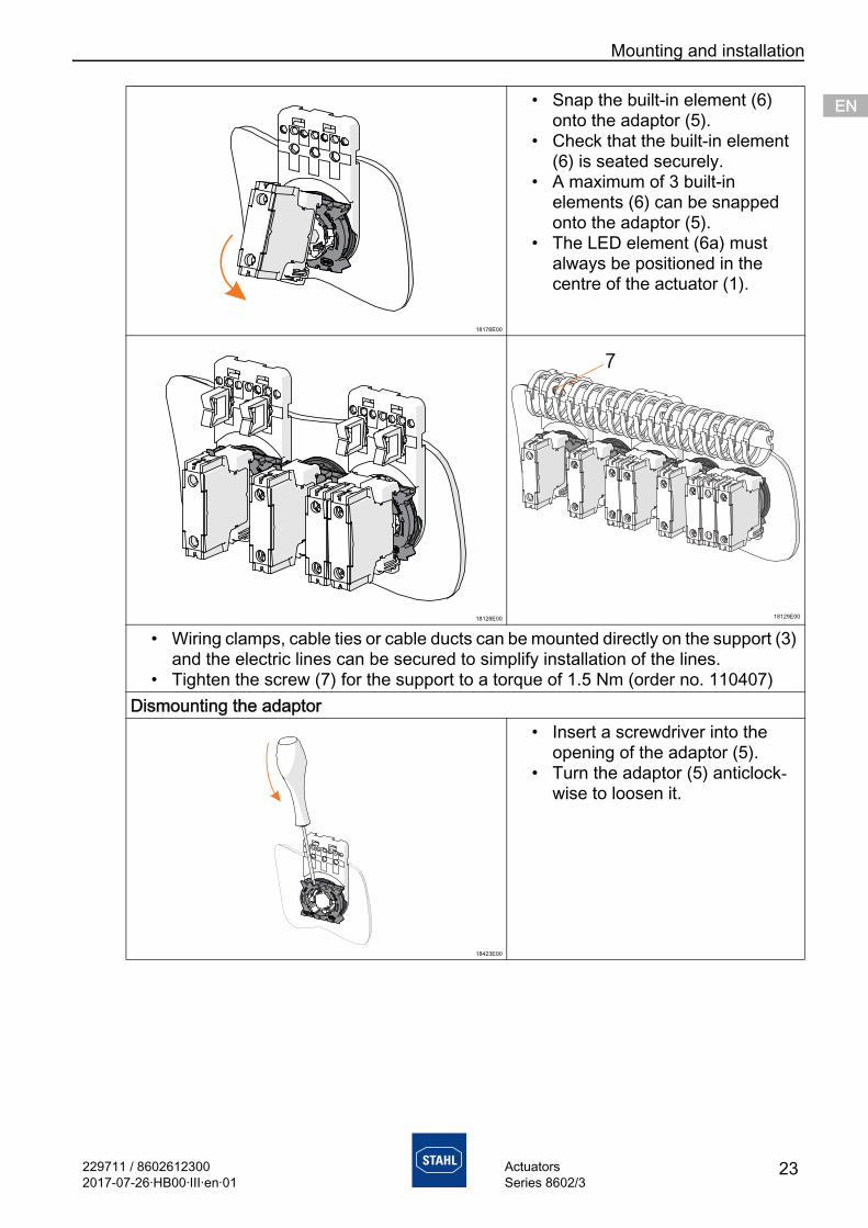
• Snap the built-in element (6) onto the adaptor (5).
• Check that the built-in element (6) is seated securely.
• A maximum of 3 built-in elements (6) can be snapped onto the adaptor (5).
• The LED element (6a) must always be positioned in the centre of the actuator (1).
18128E00 18129E00
• Wiring clamps, cable ties or cable ducts can be mounted directly on the support (3) and the electric lines can be secured to simplify installation of the lines.
• Tighten the screw (7) for the support to a torque of 1.5 Nm (order no. 110407)Dismounting the adaptor
18423E00
• Insert a screwdriver into the opening of the adaptor (5).
• Turn the adaptor (5) anticlock-wise to loosen it.
Mounting and installation
24 229711 / 86026123002017-07-26·HB00·III·en·01
ActuatorsSeries 8602/3
ENENENENENENENENENENENENENENENENENENENENENENENENEN
7.2.9 Front installation assembly
Front installation assembly with control switch type 8008/2.
19613E00
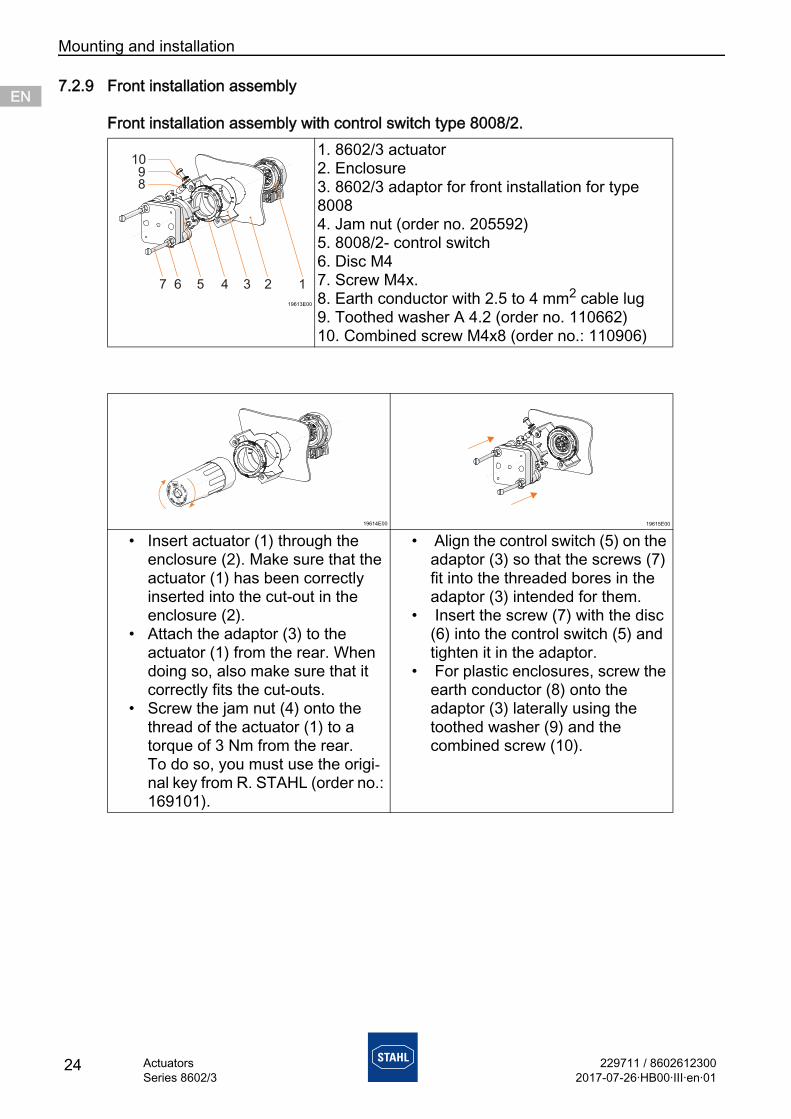
1. 8602/3 actuator2. Enclosure3. 8602/3 adaptor for front installation for type 80084. Jam nut (order no. 205592)5. 8008/2- control switch6. Disc M47. Screw M4x.8. Earth conductor with 2.5 to 4 mm2 cable lug9. Toothed washer A 4.2 (order no. 110662)10. Combined screw M4x8 (order no.: 110906)
19614E00 19615E00
• Insert actuator (1) through the enclosure (2). Make sure that the actuator (1) has been correctly inserted into the cut-out in the enclosure (2).
• Attach the adaptor (3) to the actuator (1) from the rear. When doing so, also make sure that it correctly fits the cut-outs.
• Screw the jam nut (4) onto the thread of the actuator (1) to a torque of 3 Nm from the rear. To do so, you must use the origi-nal key from R. STAHL (order no.: 169101).
• Align the control switch (5) on the adaptor (3) so that the screws (7) fit into the threaded bores in the adaptor (3) intended for them.
• Insert the screw (7) with the disc (6) into the control switch (5) and tighten it in the adaptor.
• For plastic enclosures, screw the earth conductor (8) onto the adaptor (3) laterally using the toothed washer (9) and the combined screw (10).
1098
7 6 5 4 3 2 1
229711 / 86026123002017-07-26·HB00·III·en·01
Commissioning
25ActuatorsSeries 8602/3
ENENENENENENENENENENENENENENENENENENENENENENENENEN
8 Commissioning
Before commissioning, ensure the following:• Check the mounting and installation.• Actuators must not be damaged.• Check if all screws and nuts have been tightened firmly.• Check that the seal is correctly positioned and aligned.
9 Maintenance, Overhaul, Repair
9.1 Maintenance• Consult the relevant national regulations to determine the type and extent of
inspections.• Adapt inspection intervals to the operating conditions.
During maintenance of the device, check at least:• if the device enclosure and / or protective enclosure have cracks or other visible signs
of damage, • compliance with the permissible temperatures (according to EN 60079),• if the nut is held securely in place• use only care products from CES for locking cylinders
9.2 Overhaul
9.3 Repair
DANGERExplosion hazard due to incorrect installation!Non-compliance results in severe or fatal injuries.
• Check the device for proper installation before commissioning.• Comply with national regulations.
CAUTIONRisk of electric shock or malfunction of the device due to unauthorized work!Non-compliance can result in light injuries!
• Before carrying out work on the device, switch off voltage supply.• Work performed on the device must only be carried out by authorized
and appropriately trained qualified electricians.
Observe the relevant national regulations in the country of use.
DANGERExplosion hazard due to improper repair!Non-compliance results in severe or fatal injuries.
• Repair work on the devices must be performed only by R. STAHL Schaltgeräte GmbH.
Disposal
26 229711 / 86026123002017-07-26·HB00·III·en·01
ActuatorsSeries 8602/3
ENENENENENENENENENENENENENENENENENENENENENENENENEN
9.4 Returning the device Only return or package the devices after consulting R. STAHL! Contact the responsible
representative at R. STAHL for this.
R. STAHL's customer service is available to handle returns if repair or service is required.
Contact customer service personally.
or
Go to the www.r-stahl.com website. Select "Support" > "RMA" > "RMA Request". Fill out the form.
Wait for confirmation. R. STAHL's customer service will contact you. You will receive an RMA slip after speaking with customer service.
Send the device along with the RMA slip in the packaging to R. STAHL Schaltgeräte GmbH (refer to Section 1.1 for the address).
10 Disposal• Observe national and local regulations and statutory regulation regarding disposal.• Separate materials when sending it for recycling.• Ensure environmentally friendly disposal of all components according to the statutory
regulations.
11 Accessories and Spare parts NOTICE
Malfunction or damage to the device due to the use of non-original components.Non-compliance can result in material damage.
• Use only original accessories and spare parts from R. STAHL Schaltgeräte GmbH.
For accessories and spare parts, see data sheet on our homepage www.r-stahl.com.


