mit Sicherheit geprüfte Qualität Bauart Bauart geprüft geprüft und überwacht und überwacht Bauart geprüft und überwacht L GA EINBAU- UND MONTAGEANLEITUNG KESSEL-Boden-/Deckenablauf Ecoguss Mit KESSEL-typischen Vorteilen • metallischer Verbundwerkstoff metallische Eigenschaften und dennoch korrosionsfrei • keine Erdung notwendig • Optimale Rohrreinigung durch leicht herausnehmbare Geruchverschlüsse • Teleskopisch höhenverstellbares Aufsatzstück, neigbar und drehbar zum Angleich an das Fliesenraster • Fest eingelegte Lippendichtung • vorbeugender Brandschutz mit KESSEL-Fire Kit • mit Designrosten kombinierbar Abb. zeigt Art.-Nr. 48878.64 Änderungsstand: 08/2015 Sachnummer: 325-913 Dehnfuge zwischen Endbelag und Aufsatzstück legen. DIN EN 1253 D Seite 1 GB Page 7 F Page 13
mit KESSEL-Fire Kit• mit Designrosten kombinierbarAbb. zeigt Art.-Nr. 48 878.64
Änderungsstand: 08/2015Sachnummer: 325-913
Dehnfuge zwischen Endbelag und Aufsatzstück legen.
DIN EN 1253
D Seite 1GB Page 7F Page 13
Maßangaben
min
. 25
max
. 70 x273
l132
DN
B
H14
7
x 273
• •
min
. 25
max
. 67
110
150
x13510
7DN
(Art.-Nr. 48858, 48878, 48883, 48811)
110
min
. 20
max
. 76
91
150
x135
DN
(Art.-Nr. 48458, 48478, 48483, 48411)
(Art.-Nr. 48358, 48378, 48383, 48311)
DNB
50210
80136,5
100136,5
H 120 92 92
70122,8
109
(Art.-Nr. 48758, 48778, 48783, 48711)
DNB
50210
80136,5
100136,5
H 120 92 92
70122,8
109
DNH
50100
80110
100110
70110
DNH
50100
80110
100110
70110
Abbildung zeigt 48378.11 Abbildung zeigt 48778.63
Abbildung zeigt 48811.41Abbildung zeigt 48411.11
Aussparungsmaße: 180 x 180 mm Aussparungsmaße: 180 x 180 mm
EinbauhinweiseEinbau mit Lippendichtung (im Lieferumfang des Aufsatzstückes)Bei Bodenaufbauten ohne Abdichtungsbahn, bzw. dort, wo das Ein-dringen von rückstauendem Abwasser aus der Rohrleitung in den Bo-denaufbau verhindert werden soll, wird zwischen Aufsatzstück undGrundkörper, bzw. Zwischenstück die KESSEL-Lippendichtung nachDIN EN 681-1 montiert.
Die Dichtung wird in die Nut im Grundkörper gedrückt. Damit wird einHerausziehen der Dichtung beim Höhenausgleich des Aufsatzstückesverhindert.
Einbau mit SickerwasserIst z.B. in stark belasteten Nassbereichen mit Sickerwasser zurechnen, ist die Lippendichtung zu entfernen. Dadurch kann dasanfallende Sickerwasser zwischen Aufsatzstück und Grundkör-per, bzw. Zwischenstück sicher in den Ablauf abgeführt werden.
Flexibler NiveauausgleichAufsatzstück neigbar und teleskopisch höhenverstellbar zur An-passung an das Bodenniveau sowie drehbar zur Angleichung andas Fliesenraster (1). Minimale Einbauhöhe durch Absägen (2).Mit einem KESSEL-Verlängerungsstück kann die Einbautiefemax. um 120 mm vergrößert werden (3).
Einsetzen des GeruchverschlussesGeruchverschluss in den Auslauf des Bodenteils einsetzen und durchDrehen des Oberteils verriegeln. Die Montage des Brandschutzein-satzes entnehmen Sie der Montageanleitung zum KESSEL-Fire Kit Art.-Nr. 48100.
Rohrleitungsanschluss nach DIN 19522 (SML-Rohranschluss):DN 50 70 80 100DA 58 78 83 110
BauzeitschutzabdeckungWährend der Bauzeit kann der KESSEL-Boden-/DeckenablaufEcoguss mit der mitgelieferten Bau zeit schutzabdeckung gegendas Ein dringen vonSchmutz, z.B. Mörtel,Beton, etc. geschütztwerden.
Lippendichtung
Sickerwasserableitung
Verbau des Pressdichtungsflansches (Art.-Nr. 48402)Das Verpressen von Dichtungsbahnen sind die Drehmomente wie auffolgender Tabelle aufgeführt zu beachten.
Beim Einbau in drückendes Wasser muss die Dichtungsbahn nach DIN 18195-6 mind. eine Dicke von 1,5 mm bei PIB und 2,0 mm beiECB aufweisen. Beim Einbau mit Heißbitumen ist die Temperatur imPressdichtungs-flanschbereich von max. 400°C kurzfristig (ca. 1-2 min)zulässig.Hinweis: Pressdichtungsflansch und Grundkörper sind max. 70 kgbelastbar.
Werkstoff Dichtbahn Anzugsmoment empfohlen*
Bitumenbahn 4-6 NmPIB mit Bitumenbahn 4-6 NmverklebtBitumenbahn mit Träger- 6-8 Nmeinlage aus GlasgewebeElastomere Sperrbahn 48982 4-6 Nm
(* in Anlehnung an DIN18195)
Einbauvorschlag
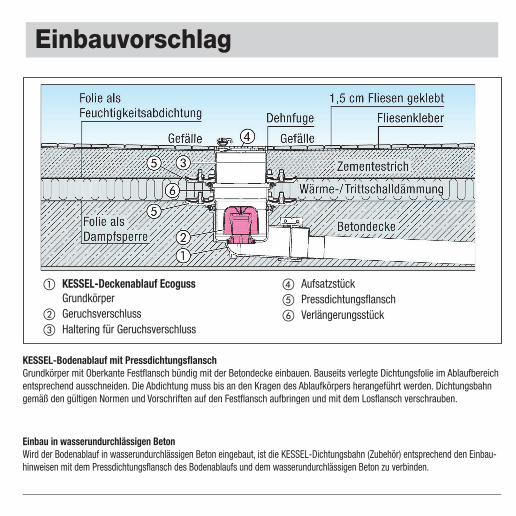
KESSEL-Bodenablauf mit PressdichtungsflanschGrundkörper mit Oberkante Festflansch bündig mit der Betondecke einbauen. Bauseits verlegte Dichtungsfolie im Ablaufbereichentsprechend ausschneiden. Die Abdichtung muss bis an den Kragen des Ablaufkörpers herangeführt werden. Dichtungsbahngemäß den gültigen Normen und Vorschriften auf den Festflansch aufbringen und mit dem Losflansch verschrauben.
Einbau in wasserundurchlässigen BetonWird der Bodenablauf in wasserundurchlässigen Beton eingebaut, ist die KESSEL-Dichtungsbahn (Zubehör) entsprechend den Einbau-hinweisen mit dem Pressdichtungsflansch des Bodenablaufs und dem wasserundurchlässigen Beton zu verbinden.
� KESSEL-Deckenablauf EcogussGrundkörper
� Geruchsverschluss� Haltering für Geruchsverschluss
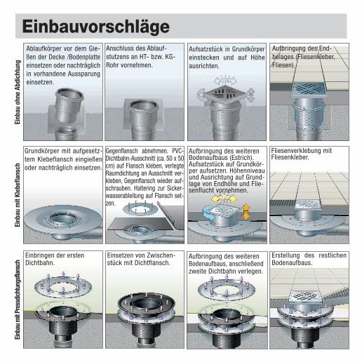
EinbauvorschlägeAblaufkörper vor dem Gie-ßen der Decke /Bodenplatteeinsetzen oder nachträglichin vorhandene Aussparungeinsetzen.
Anschluss des Ablauf-stutzens an HT- bzw. KG-Rohr vornehmen.
Aufsatzstück in Grundkörpereinstecken und auf Höheausrichten.
Aufbringung des End-belages (Fliesenkleber,Fliesen).
Grundkörper mit aufgesetz-tem Klebeflansch eingießenoder nachträglich einsetzen.
Gegenflansch abnehmen. PVC-Dichtbahn-Ausschnitt (ca. 50 x 50cm) auf Flansch kleben, verlegteRaumdichtung an Ausschnitt ver-kleben, Gegenflansch wieder auf-schrauben. Haltering zur Sicker-wasserableitung auf Flansch set-zen.
Aufbringung des weiterenBodenaufbaus (Estrich).Aufsatzstück auf Grundkör-per aufsetzen. Höhenniveauund Ausrichtung auf Grund-lage von Endhöhe und Flie-senflucht vornehmen.
Fliesenverklebung mit Fliesenkleber.
Einbringen der erstenDichtbahn.
Einsetzen von Zwischen-stück mit Dichtflansch.
Aufbringung des weiterenBodenaufbaus, anschließendzweite Dichtbahn verlegen.
Erstellung des restlichen Bodenaufbaus.
Einb
au o
hne
Abdi
chtu
ngEi
nbau
mit
Kleb
efla
nsch
Einba
u m
it Pr
essd
ichtu
ngsf
lansc
h
Schallschutz
25
min
. 95
min
110
Nach Messung des Fraunhofer Instituts Stuttgart: Boden-/Deckenablauf Ecoguss- 16 dB(A) nach DIN 4109 - 14 dB(A) nach VDI 4100 SST IIINach Messung des Fraunhofer Instituts Stuttgart: Boden-/Deckenablauf Ecoguss mit Fire-Kit- 23 dB(A) nach DIN 4109 - 20 dB(A) nach VDI 4100 SST III
INSTRUCTIONS FOR INSTALLATION, OPERATION AND MAINTENANCE
KESSEL-floor/roof drainEcoguss
With typical KESSEL advantages
• Metallic compound material, metallic properties and yetstill corrosion-free
• No earthing necessary• Optimum pipe cleaning thanks to easy removal of odour
traps• Telescopic height adjustment of attachment, can be
tilted and turned to match the tile pattern• Firmly inserted lip seal• Preventative fire protection with
KESSEL Fire Kit• Can be combined with design coversPicture shows Art.’# 48 878.64
Edition: 08/2015Number: 325-913
Place expansion joint between end cover and attachment piece.
DIN EN 1253
Dimensions
min
. 25
max
. 70 x273
l132
DN
B
H14
7
x 273
• •
min
. 25
max
. 67
110
150
x13510
7DN
(Art.# 48858, 48878, 48883, 48811)
110
min
. 20
max
. 76
91
150
x135
DN
0(Art.# 48458, 48478, 48483, 48411)
(Art.# 48358, 48378, 48383, 48311)
DNB
50210
80136,5
100136,5
H 120 92 92
70122,8
109
(Art.# 48758, 48778, 48783, 48711)
DNB
50210
80136,5
100136,5
H 120 92 92
70122,8
109
DNH
50100
80110
100110
70110
DNH
50100
80110
100110
70110
Picture shows 48378.11 Picture shows 48778.63
Picture shows 48811.41Picture shows 48411.11
Installation area: 180 x 180 mm Installation area: 180 x 180 mm
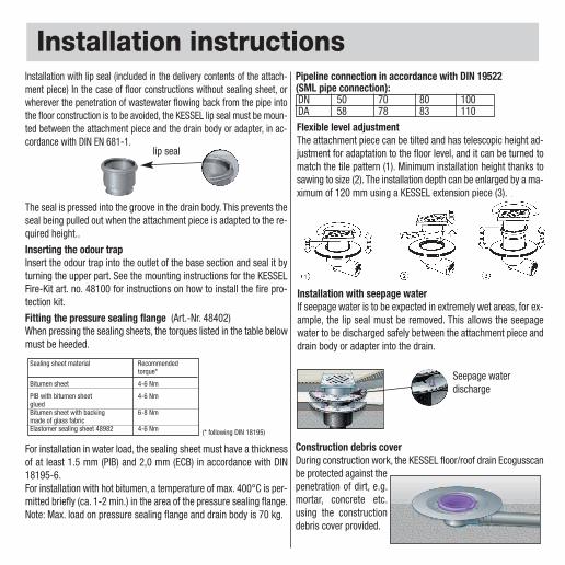
Installation instructionsInstallation with lip seal (included in the delivery contents of the attach-ment piece) In the case of floor constructions without sealing sheet, orwherever the penetration of wastewater flowing back from the pipe intothe floor construction is to be avoided, the KESSEL lip seal must be moun-ted between the attachment piece and the drain body or adapter, in ac-cordance with DIN EN 681-1.
The seal is pressed into the groove in the drain body. This prevents theseal being pulled out when the attachment piece is adapted to the re-quired height..
Installation with seepage waterIf seepage water is to be expected in extremely wet areas, for ex-ample, the lip seal must be removed. This allows the seepagewater to be discharged safely between the attachment piece anddrain body or adapter into the drain.
Flexible level adjustmentThe attachment piece can be tilted and has telescopic height ad-justment for adaptation to the floor level, and it can be turned tomatch the tile pattern (1). Minimum installation height thanks tosawing to size (2). The installation depth can be enlarged by a ma-ximum of 120 mm using a KESSEL extension piece (3).
Inserting the odour trapInsert the odour trap into the outlet of the base section and seal it byturning the upper part. See the mounting instructions for the KESSELFire-Kit art. no. 48100 for instructions on how to install the fire pro-tection kit.
Pipeline connection in accordance with DIN 19522 (SML pipe connection):DN 50 70 80 100DA 58 78 83 110
Construction debris coverDuring construction work, the KESSEL floor/roof drain Ecogusscanbe protected against thepenetration of dirt, e.g.mortar, concrete etc.using the constructiondebris cover provided.
lip seal
Seepage waterdischarge
Fitting the pressure sealing flange (Art.-Nr. 48402)When pressing the sealing sheets, the torques listed in the table belowmust be heeded.
For installation in water load, the sealing sheet must have a thicknessof at least 1.5 mm (PIB) and 2,0 mm (ECB) in accordance with DIN18195-6.For installation with hot bitumen, a temperature of max. 400°C is per-mitted briefly (ca. 1-2 min.) in the area of the pressure sealing flange.Note: Max. load on pressure sealing flange and drain body is 70 kg.
Sealing sheet material Recommended torque*
Bitumen sheet 4-6 Nm
PIB with bitumen sheet 4-6 NmgluedBitumen sheet with backing 6-8 Nmmade of glass fabricElastomer sealing sheet 48982 4-6 Nm (* following DIN 18195)
Assembly proposal
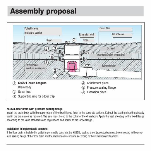
KESSEL floor drain with pressure sealing flangeInstall the drain body with the upper edge of the fixed flange flush to the concrete surface. Cut out the sealing sheeting alreadylaid in the drain area as required. The seal must be up to the collar of the drain body. Apply the seal sheeting to the fixed flangeaccording to the valid standards and regulations and screw to the loose flange.
Installation in impermeable concreteIf the floor drain is installed in water impermeable concrete, the KESSEL sealing sheet (accessories) must be connected to the pres-sure sealing flange of the floor drain and the impermeable concrete according to the installation instructions.
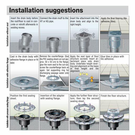
Installation suggestionsInsert the drain body beforethe roof/floor is cast in con-crete or retrofit afterwards inexisting recess.
Connect the drain muff to theHT or KG pipe.
Insert the attachment into thedrain body and align to theright height.
Apply the final flooring (tileadhesive, tiles).
Cast in the drain body withadhesive flange in place or fitlater.
Remove the counterflange. Gluethe PVC sealing sheet cut-out (ap-prox. 50 x 50 cm) to the flange,glue the room seal to the cut-out,screw the counterflange back onagain. Set supporting ring fordischarging seepage water ontoflange.
Apply the next layer of floorstructure (screed). Insert at-tachment piece onto drainbody. Undertake height level-ling and alignment on the basisof final height and tilealignment.
Glue tiles in place with tile adhesive.
Position the first sealingsheet.
Insertion of the adapterwith sealing flange.
Apply the further floor struc-ture, then lay the secondsealing sheet.
Finish the floor structure.
Inst
alla
tion
with
out s
eal
Inst
alla
tion
with
adh
esiv
e fla
nge
Instal
lation
with
pres
sure
seali
ng fla
nge
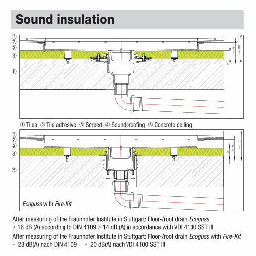
Sound insulation
25
min
. 95
min
. 110
After measuring of the Fraunhofer Institute in Stuttgart: Floor-/roof drain Ecoguss≥ 16 dB (A) according to DIN 4109 ≥ 14 dB (A) in accordance with VDI 4100 SST IIIAfter measuring of the Fraunhofer Institute in Stuttgart: Floor-/roof drain Ecoguss with Fire-Kit- 23 dB(A) nach DIN 4109 - 20 dB(A) nach VDI 4100 SST III
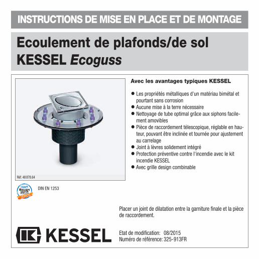
• Les propriétés métalliques d'un matériau bimétal etpourtant sans corrosion
• Aucune mise à la terre nécessaire• Nettoyage de tube optimal grâce aux siphons facile-
ment amovibles• Pièce de raccordement télescopique, réglable en hau-
teur, pouvant être inclinée et tournée pour ajustementau carrelage
• Joint à lèvres solidement intégré• Protection préventive contre l'incendie avec le kit
incendie KESSEL• Avec grille design combinable
Réf. 48 878.64
Etat de modification: 08/2015Numéro de référence: 325-913FR
Placer un joint de dilatation entre la garniture finale et la piècede raccordement.
DIN EN 1253
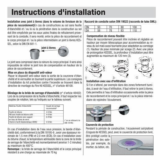
Instructions d'installationInstallation avec joint à lèvres (dans le volume de livraison de lapièce de raccordement)En cas de constructions au sol sans feuilled'étanchéité et / ou là où la pénétration dans la construction au soldoit être empêchée par les eaux usées finales de refoulement prove-nant de la conduite, il sera monté, entre la pièce de raccordement etle corps principal et / ou la pièce intermédiaire un joint à lèvres KES-SEL, selon la DIN EN 681-1.
Le joint sera compressé dans la rainure du corps principal. Il sera ainsiimpossible de retirer le joint lors de compensation en hauteur de lapièce de raccordement.
Installation avec eau d'infiltrationSi l'on s'attend, par exemple dans des zones fortement humi-des, à avoir de l'eau d'infiltration, il faut retirer le joint à lèvres.Cela permettra à l'eau d'infiltration occasionnelle entre la piècede raccordement et le corps principal et / ou la pièce intermé-diaire de rejoindre l'écoulement.
Compensation de niveau flexiblePièce de raccordement pouvant être inclinée et réglable enhauteur par moyen télescopique pour accommodation au ni-veau du sol mais aussi tournante pour adaptation au carrelage(1). Hauteur de pose minimale par sciage (2). Avec une piècede prolongation KESSEL, la profondeur d'installation peut êtreaugmentée au maximum de 120 mm (3).
Mise en place du dispositif anti-odeurPlacer le dispositif anti-odeur dans la sortie de la couronne d'étan-chéité et le verrouiller en tournant la partie supérieure. Les consignesd'installation du kit protection contre l'incendie se trouvent dans ladirective de montage du Fire Kit KESSEL, n° d'article 48100.
Raccord de conduite selon DIN 19522 (raccords de tube SML):
DN 50 70 80 100DA 58 78 83 110
Couvercle de protectionPendant la période de construction, l'écoulement sol/plafondEcoguss de KESSEL peut, avec le couvercle de protection livré,être protégé contre lapénétration des sale-tés, par exemple, dumortier, du béton, etc.
joint à lèvres
Blindage de la bride de serrage d'étanchéité (n° d'article 48402)Lors de la compression de la feuille d'étanchéité, il faut respecter lescouples de rotation, tels qu'indiqués sur le tableau suivant.
En cas d'installation dans de l'eau sous pression, la bande d'étan-chéité doit, conformément à la DIN 18195-6 , avoir une épaisseur mi-nimale de 1,5 mm (PIB) et 2,0 mm (ECB). En cas d'installation avecdu bitume chaud, la température admissible dans la zone de la bridede serrage de l'étanchéité est momentanément (environ 1-2 minutes)au maximum de 400°C. Remarque : la bride de serrage de l'étanchéité et le corps principalrésistent à une charge au maximale de 70 kg
Matériau Feuille d'étanchéité Couple de serrage recommandé*
Feuille de bitume 4-6 NmPIB avec feuille de bitume collé 4-6 NmFeuille de bitume avec support 6-8 Nmen tissu de fibres de verreChemin d'arrêt élastomérique 48982 4-6 Nm
(* en se référant à laDIN 18195)
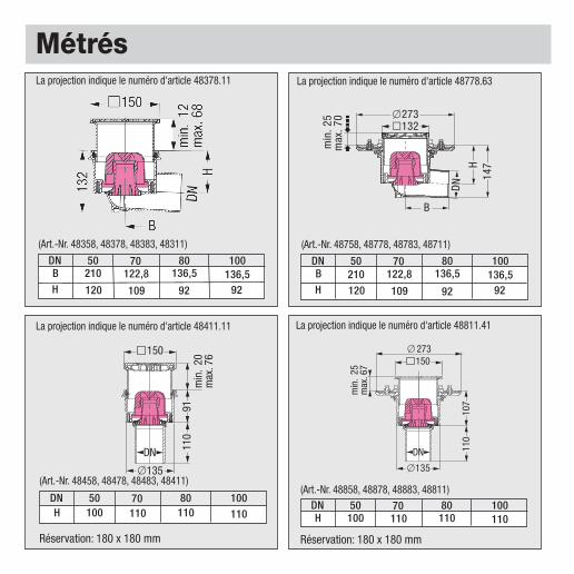
Métrés
min
. 25
max
. 70 x273
l132
DN
B
H14
7
x 273
• •
min
. 25
max
. 67
110
150
x13510
7DN
(Art.-Nr. 48858, 48878, 48883, 48811)
110
min
. 20
max
. 76
91
150
x135
DN
(Art.-Nr. 48458, 48478, 48483, 48411)
(Art.-Nr. 48358, 48378, 48383, 48311)
DNB
50210
80136,5
100136,5
H 120 92 92
70122,8
109
(Art.-Nr. 48758, 48778, 48783, 48711)
DNB
50210
80136,5
100136,5
H 120 92 92
70122,8
109
DNH
50100
80110
100110
70110
DNH
50100
80110
100110
70110
La projection indique le numéro d'article 48378.11 La projection indique le numéro d'article 48778.63
La projection indique le numéro d'article 48811.41La projection indique le numéro d'article 48411.11
Réservation: 180 x 180 mm Réservation: 180 x 180 mm
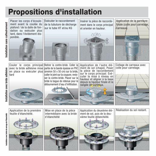
Propositions d'installation
Ecoulement au sol KESSEL avec bride de serrage de l'étanchéitéCorps principal avec bord supérieur de bride ferme à monter au plafond en béton. Découper du côté construction le film d'étan-chéité placé en fonction de la zone d'écoulement. Le calfeutrement doit être exécuté jusqu'au col du corps d'écoulement. Intro-duire la bande d'étanchéité sur la bride fixe selon les normes en vigueur et les instructions et visser avec la bride détachée.
Installation dans du béton étancheSi l'écoulement au sol est installé dans du béton étanche, la bande d'étanchéité KESSEL (accessoires) doit être connectée, conformé-ment aux instructions d'installation, à la bride de serrage de l'étanchéité de l'écoulement au sol et au béton étanche.
� Ecoulement de plafond Kessel Ecoguss-Corps principal
� Siphons� Bague de retenue pour le siphon
� Pièce de raccordement� Bride de serrage de l'étanchéité� Pièce de prolongation
Film comme étanchéitéanti-humidité
Film comme barrage de vapeur
Joint dedilatation
Inclinaisons Inclinaisons
Colle pour carrelage
1,5 cm de carreaux collés
Aire de ciment
Plafond en béton
Isolation contre chaleur et passage à pied
Propositions d'installationPlacer les corps d'écoule-ment avant la coulée duplafond / de la dalle de fon-dation ou exécuter plustard, dans l'évidement dis-ponible.
Exécuter le raccordementde la tubulure de déchargesur le tube HT et/ou KG
Insérer la pièce de raccorde-ment dans le corps principalet orienter en hauteur.
Application de la garniturefinale (colle pour carrelage,carreaux).
Couler le corps principalavec la bride adhésive miseen place ou exécuter plustard
Retirer la contre-bride. Coller lapartie de la bande épaisse en PVC(environ 50 x 50 cm) sur la bride,coller le joint sur la coupure, revis-ser la contre-bride. Placer sur labride la bague de retenue pour ledétournement d'eau d'infiltration.
Application de l'autre élé-ment de sol (chape). Poserla pièce de raccordementsur le corps principal. Exé-cuter la mise à niveau enhauteur et aligner à la basedepuis la hauteur finale et larangée de carreaux.
Collage de carreaux aveccolle pour carrelage.
Application de la premièrefeuille d'étanchéité.
Mise en place de la pièceintermédiaire avec la brided'étanchéité
Application du deuxième élé-ment de sol, puis de la deu-xième feuille détanchéité.
Réalisation du sol restant.
Inst
alla
tion
sans
cal
feut
rem
ent
Inst
alla
tion
avec
brid
e ad
hési
veIn
stall
ation
avec
brid
e de s
erra
ge d
e l'ét
anch
éité
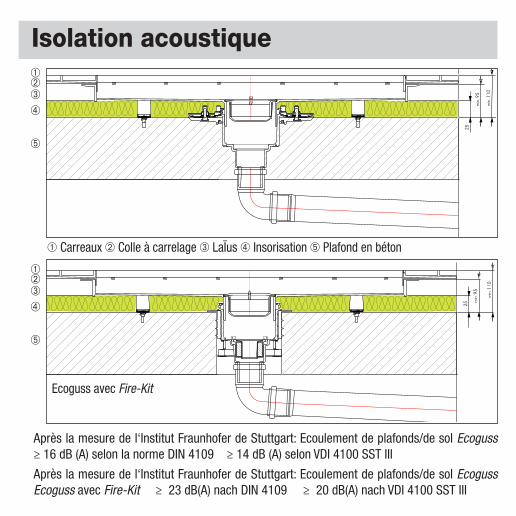
Isolation acoustique
25
min
. 95
min
. 110
Après la mesure de l‘Institut Fraunhofer de Stuttgart: Ecoulement de plafonds/de sol Ecoguss≥ 16 dB (A) selon la norme DIN 4109 ≥ 14 dB (A) selon VDI 4100 SST III
Après la mesure de l‘Institut Fraunhofer de Stuttgart: Ecoulement de plafonds/de sol EcogussEcoguss avec Fire-Kit ≥ 23 dB(A) nach DIN 4109 ≥ 20 dB(A) nach VDI 4100 SST III
➀ Carreaux ➁ Colle à carrelage ➂ LaÏus ➃ Insorisation ➄ Plafond en béton