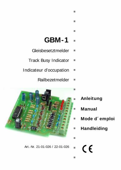
n n n GBM-1 n Gleisbesetztmelder n Track Busy Indicator n Indicateur d’occupation n Railbezetmelder n n n Anleitung n Manual n Mode d´emploi n Handleiding n Art.-Nr. 21-01-026 / 22-01-026 n n
(Pages I to III in the centre of this handbook are removeable.)
GBM-1 English
Page 21
!
How to use this manualIf you have no specialist technical training, this manual gives step-by-step instructions for safe and correct assembly of the kit and fitting ofthe ready-built module, and operation. Before you start, we advise youto read the whole manual, particularly the chapter on safetyinstructions and the FAQ chapter. You will then know where to takecare and how to prevent mistakes which take a lot of effort to correct.
Keep this manual safely so that you can solve problems in the future. Ifyou pass the kit or the ready-built module on to another person, pleasepass on the manual with it.
Intended use
Caution:
Integrated circuits are very sensitive to static electricity. Do not touchcomponents without first discharging yourself. Touching a radiator orother grounded metal part will discharge you.
The kit or the ready-built module can be assembled or operated usingthis manual. The ready-built module is designed for use in modelrailways. It indicates occupied tracks on four independent tracksections.
The kit and the ready-built module should not be assembled or fitted bychildren under the age of 14.
Reading, understanding and following the instructions in this manualare mandatory for the user.
Any other use is inappropriate and invalidates any guarantees.
English GBM-1
Page 22
Safety instructions
Mechanical hazards
Cut wires can have sharp ends and can cause serious injuries. Watchout for sharp edges when you pick up the PCB.
Visibly damaged parts can cause unpredictable danger. Do not usedamaged parts: recycle and replace them with new ones.
Electrical hazards
§ Touching powered, live components,§ touching conducting components which are live due to malfunction,§ short circuits,§ connecting the circuit to another voltage than specified,§ impermissibly high humidity,§ condensation build upcan cause serious injury due to electrical shock. Take the followingprecautions to prevent this danger:
§ Never perform wiring on a powered module.§ Assembling and mounting the kit should only be done in closed,
clean, dry rooms. Beware of humidity.§ Only use low power for this module as described in this manual and
only use certified transformers.§ Connect transformers and soldering irons only in approved mains
sockets installed by an authorised electrician.§ Observe cable diameter requirements.§ After condensation build up, allow a minimum of 2 hours for
dispersion.§ Use only original spare parts if you have to repair the kit or the
ready-built module.
GBM-1 English
Page 23
Fire risk
Touching flammable material with a hot soldering iron can cause fire,which can result in injury or death through burns or suffocation.Connect your soldering iron or soldering station only when actuallyneeded. Always keep the soldering iron away from inflammablematerials. Use a suitable soldering iron stand. Never leave a hotsoldering iron or station unattended.
Thermal danger
A hot soldering iron or liquid solder accidentally touching your skin cancause skin burns. As a precaution:
§ use a heat-resistant mat during soldering,§ always put the hot soldering iron in the soldering iron stand,§ point the soldering iron tip carefully when soldering, and§ remove liquid solder with a thick wet rag or wet sponge from the
soldering tip.
Dangerous environments
A working area that is too small or cramped is unsuitable and can causeaccidents, fires and injury. Prevent this by working in a clean, dry roomwith enough freedom of movement.
Other dangers
Children can cause any of the accidents mentioned above because theyare inattentive and not responsible enough. Children under the age of 14should not be allowed to work with this kit or the ready-built module.
Little children can swallow small components with sharp edges, withfatal results! Do not allow components to reach small children.
In schools, training centres, clubs and workshops, assembly must besupervised by qualified personnel.
In industrial institutions, health and safety regulations applying toelectronic work must be adhered to.
English GBM-1
Page 24
EMC declarationThis product is developed in accordance with the European standardsEN 55014 and EN 50082-1, tested corresponding to the EC - directive89/336/EWG (EMVG of 09/11/1992, electromagnetic tolerance) andmeets legal requirements.
To guarantee the electromagnetic tolerance you must take thefollowing precautions:
§ Connect the transformer only to an approved mains socket installedby an authorised electrician.
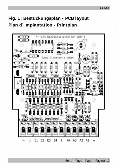
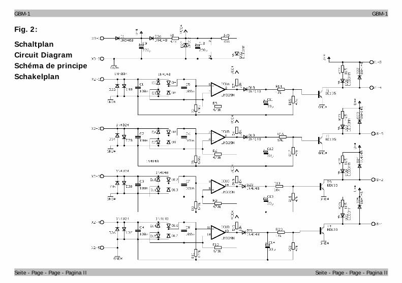
§ Make no changes to the original parts and accurately follow theinstructions, circuit diagram and PCB layut included with thismanual.
§ Use only original spare parts if you have to repair the kit or theready-built module.
Operation overviewThe module indicates occupied tracks on four independent tracksections. It can be used universally in all systems (d.c. voltage, a.c.voltage and digital systems).
It is connected between the analogue transformer or the digital centraland the chosen track section and monitors all connected loads (e.g.engines or carriages with lighting) located on the track sectionconcerned. Carriages without lighting running on a two-rail system turninto connected loads if the axle is painted with conducting varnish.Connected electrical loads located in a switched-off track section can bedetected if an additional resistor is inserted.
Detection is made against ground. Very small currents are sufficient.Digital check-back decoders can be connected directly to the outputs ofthe module.
GBM-1 English
Page 25
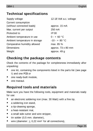
Technical specificationsSupply voltage 12-18 Volt a.c. voltageCurrent consumption(without connected loads) approx. 15 mAMax. current per output 250 mAProtected to IP 00Ambient temperature in use 0 - + 60 °CAmbient temperature in storage -10 - + 80 °CComparative humidity allowed max. 85 %Dimensions approx. 73 x 80 mmWeight approx. 49 g
Checking the package contentsCheck the contents of the package for completeness immediately afterunpacking:
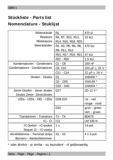
§ one kit, containing the components listed in the parts list (see pageI) and one PCB or
§ one ready-built module,§ one manaul.
Required tools and materialsMake sure you have the following tools, equipment and materials readyfor use:
§ an electronic soldering iron (max. 30 Watt) with a fine tip,§ a soldering iron stand,§ a tip-cleaning sponge,§ a heat-resistant mat,§ a small side cutter and wire stripper,§ tin solder (0,5 mm. diameter),§ wire (diameter: > 0,22 mm² for all connections),
English GBM-1
Page 26
!
§ a pair of tweezers and long nose pliers (not necessary for theready-built module),
§ a lamp or bulb for the functional test.
Safe and correct soldering
Caution:
Incorrect soldering can cause dangers through fires and heat. Avoidthese dangers by reading and following the directions given in thechapter Safety instructions. If you have had training in soldering youcan skip this chapter.
§ Use a small soldering iron with max. 30 Watt. Keep the soldering tipclean so the heat of the soldering iron is applied to the solder pointeffectively.
§ Only use electronic tin solder with flux.§ When soldering electronic circuits never use soldering-water or
soldering grease. They contain acids that can corrode componentsand copper tracks.
§ Solder quickly: holding the iron on the joints longer than necessarycan destroy components and can damage copper tracks orsoldering eyes.
§ Observe correct polarity orientation of semi-conductors, LEDselectrolytic capacitors and integrated circuits before soldering andensure that the solder time does not exceed 5 seconds, otherwisecomponents can be damaged.
§ Apply the soldering tip to the soldering spot in such a way that the partand the soldering eye are heated at the same time. Simultaneously addsolder (not too much). As soon as the solder becomes liquid take itaway. Hold the soldering tip at the spot for a few seconds so that thesolder flows into the joint, then remove the soldering iron.
§ Do not move the component for about 5 seconds after soldering.
GBM-1 English
Page 27
§ To make a good soldering joint you must use a clean andunoxidised soldering tip. Clean the soldering tip with a damp pieceof cloth, a damp sponge or a piece of silicon cloth.
§ Cut the wires after soldering directly above the PCB solder side witha side cutter.
§ After placing the parts, please double check for correct polarity.Check the PCB tracks for solder bridges and short circuits createdby accident. This would cause faulty operation or, in the worstcase, damage. You can remove excess solder by putting a cleansoldering tip on the spot. The solder will become liquid again andflow from the soldering spot to the soldering tip.
Assembling the kitYou can skip this part if you have purchased a ready-built module.
Preparation
Put the sorted components in front of you on your workbench. Theseparate electronic components have the following special features youshould take into account to prevent mistakes in assembling:
Resistors
Resistors reduce current. Their mounting orientation is of noimportance. The value of resistors for smaller power ratings(under 5 W) is indicated through colour rings. Every colourstands for another figure.
Value Colour rings470 Ω yellow - violet - brown (gold)1,5 kΩ brown - green - red (gold)10 kΩ brown - black - orange (gold)47 kΩ yellow - violet - orange (gold)470 kΩ yellow - violet - yellow (gold)
The colour ring in brackets indicates the tolerance of theresistor which here is of no importance.
English GBM-1
Page 28
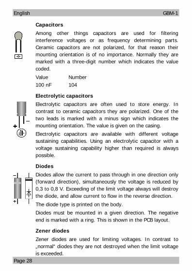
Capacitors
Among other things capacitors are used for filteringinterference voltages or as frequency determining parts.Ceramic capacitors are not polarized, for that reason theirmounting orientation is of no importance. Normally they aremarked with a three-digit number which indicates the valuecoded.
Value Number100 nF 104
Electrolytic capacitors
Electrolytic capacitors are often used to store energy. Incontrast to ceramic capacitors they are polarized. One of thetwo leads is marked with a minus sign which indicates themounting orientation. The value is given on the casing.
Electrolytic capacitors are available with different voltagesustaining capabilities. Using an electrolytic capacitor with avoltage sustaining capability higher than required is alwayspossible.
Diodes
Diodes allow the current to pass through in one direction only(forward direction), simultaneously the voltage is reduced by0,3 to 0,8 V. Exceeding of the limit voltage always will destroythe diode, and allow current to flow in the reverse direction.
The diode type is printed on the body.
Diodes must be mounted in a given direction. The negativeend is marked with a ring. This is shown in the PCB layout.
Zener diodes
Zener diodes are used for limiting voltages. In contrast to„normal“ diodes they are not destroyed when the limit voltageis exceeded.
GBM-1 English
Page 29
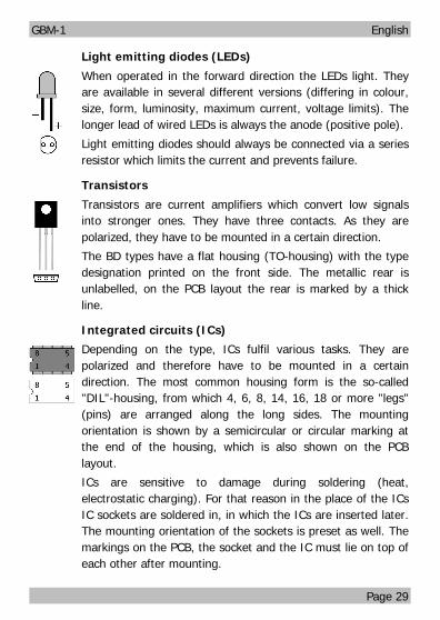
Light emitting diodes (LEDs)
When operated in the forward direction the LEDs light. Theyare available in several different versions (differing in colour,size, form, luminosity, maximum current, voltage limits). Thelonger lead of wired LEDs is always the anode (positive pole).
Light emitting diodes should always be connected via a seriesresistor which limits the current and prevents failure.
Transistors
Transistors are current amplifiers which convert low signalsinto stronger ones. They have three contacts. As they arepolarized, they have to be mounted in a certain direction.
The BD types have a flat housing (TO-housing) with the typedesignation printed on the front side. The metallic rear isunlabelled, on the PCB layout the rear is marked by a thickline.
Integrated circuits (ICs)
Depending on the type, ICs fulfil various tasks. They arepolarized and therefore have to be mounted in a certaindirection. The most common housing form is the so-called"DIL"-housing, from which 4, 6, 8, 14, 16, 18 or more "legs"(pins) are arranged along the long sides. The mountingorientation is shown by a semicircular or circular marking atthe end of the housing, which is also shown on the PCBlayout.
ICs are sensitive to damage during soldering (heat,electrostatic charging). For that reason in the place of the ICsIC sockets are soldered in, in which the ICs are inserted later.The mounting orientation of the sockets is preset as well. Themarkings on the PCB, the socket and the IC must lie on top ofeach other after mounting.
English GBM-1
Page 30
!
!
Terminal strips
Terminal strips are solder-in screw-type terminals. They provide asolder-free and safe connection of the cables to the circuit, which canstill be seperated any time. When several terminal strips have to bemounted side by side, they have to be put together before mounting.
Assembling the kit
Start the assembly with the resistors. First solder the components onthe solder side of the PCB and then cut the excess wires with the sidecutter, as short as possible. Insert the wire bridges Br1 and Br2. Usethe off-cut wires of the resistors.
Continue the assembly with the diodes. Then insert and solder in theIC-socket, the capacitors, the LEDs and the transistors.
Caution:
Diodes, ICs, electrolytic capacitors and transistors must be placed in theright direction! If you solder them the wrong way the affected parts can bedamaged when you connect the power. In the worst case the whole circuitcan be damaged. In any case, a wrongly connected part will not function.
Next solder in the terminal strips. Put together the terminal stripsbefore mounting them. Finally, insert the IC into the soldered IC-socket.
Caution:
Do not touch the ICs without first discharging yourself by touching aradiator or other grounded metal parts. Do not bend the "legs" of theICs when inserting them into the sockets. Check that the markings onthe PCB, the socket and the IC show to the same direction.
Performing a visual checkDue to material defects and/or improper assembly there may be risks ofinjury. Transport damage to ready-built modules is also possible. Soyou must perform a visual check after the assembly or after unpackingthe module.
GBM-1 English
Page 31
!
!
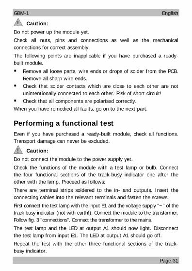
Caution:
Do not power up the module yet.
Check all nuts, pins and connections as well as the mechanicalconnections for correct assembly.
The following points are inapplicable if you have purchased a ready-built module.
§ Remove all loose parts, wire ends or drops of solder from the PCB.Remove all sharp wire ends.
§ Check that solder contacts which are close to each other are notunintentionally connected to each other. Risk of short circuit!
§ Check that all components are polarised correctly.When you have remedied all faults, go on to the next part.
Performing a functional testEven if you have purchased a ready-built module, check all functions.Transport damage can never be excluded.
Caution:
Do not connect the module to the power supply yet.
Check the functions of the module with a test lamp or bulb. Connectthe four functional sections of the track-busy indicator one after theother with the lamp. Proceed as follows:
There are terminal strips soldered to the in- and outputs. Insert theconnecting cables into the relevant terminals and fasten the screws.
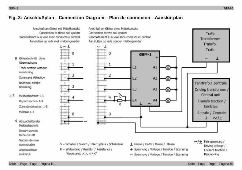
First connect the test lamp with the input E1 and the voltage supply "~" of thetrack busy indicator (not with earth!). Connect the module to the transformer.Follow fig. 3 "connections". Connect the transformer to the mains.
The test lamp and the LED at output A1 should now light. Disconnectthe test lamp from input E1. The LED at output A1 should go off.
Repeat the test with the other three functional sections of the track-busy indicator.
English GBM-1
Page 32
!
!
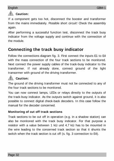
Caution:
If a component gets too hot, disconnect the booster and transformerfrom the mains immediately. Possible short circuit! Check the assemblyagain.
After performing a successful function test, disconnect the track busyindicator from the voltage supply and continue with the connection ofthe module.
Connecting the track busy indicatorFollow the connections diagram fig. 3. First connect the inputs E1 to E4with the mass connection of the four track sections to be monitored.Next connect the power supply cables of the track-busy indicator to thetransformer. If not already done, connect ground of the lighttransormer with ground of the driving transformer.
Caution:
The ground of the driving transformer must not be connected to any ofthe four track sections to be monitored.
You can now connect lamps, LEDs or relays directly to the outputs ofthe track-busy indicator. As the outputs switch against ground, it is alsopossible to connect digital check-back decoders. In this case follow themanual for the decoder concerned.
Monitoring of cut off track sections
Track sections to be cut off in operation (e.g. in a shadow station) canalso be monitored with the track busy indicator. For that purpose aresistor with a value between 1 kΩ und 4,7 kΩ has to be mounted inthe wire leading to the concerned track section so that it shunts theswitch when the track section is cut off (s. fig. 3 connection to E4).
GBM-1 English
Page 33
!
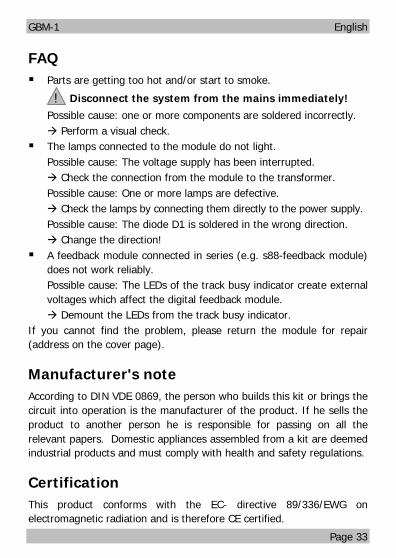
FAQ§ Parts are getting too hot and/or start to smoke.
Disconnect the system from the mains immediately!
Possible cause: one or more components are soldered incorrectly.à Perform a visual check.
§ The lamps connected to the module do not light.Possible cause: The voltage supply has been interrupted.à Check the connection from the module to the transformer.Possible cause: One or more lamps are defective.à Check the lamps by connecting them directly to the power supply.Possible cause: The diode D1 is soldered in the wrong direction.à Change the direction!
§ A feedback module connected in series (e.g. s88-feedback module)does not work reliably.Possible cause: The LEDs of the track busy indicator create externalvoltages which affect the digital feedback module.à Demount the LEDs from the track busy indicator.
If you cannot find the problem, please return the module for repair(address on the cover page).
Manufacturer's noteAccording to DIN VDE 0869, the person who builds this kit or brings thecircuit into operation is the manufacturer of the product. If he sells theproduct to another person he is responsible for passing on all therelevant papers. Domestic appliances assembled from a kit are deemedindustrial products and must comply with health and safety regulations.
CertificationThis product conforms with the EC- directive 89/336/EWG onelectromagnetic radiation and is therefore CE certified.
English GBM-1
Page 34
Conditions of warrantyThis product is guaranteed for two years. The warranty includes thecorrection of faults which can be proved to be due to material failure orfactory flaw. As we have no control over the correct and properassembly and mounting we can only guarantee the quality of thecomponents and the completeness of kits. We guarantee the functionof the parts according to the parameters in not mounted state as wellas the adherence to the technical specifications of the circuit whenassembled and connected according to the manual.Other claims are excluded. By law, we are not responsible for damages orsecondary damages in connection with this product. We retain the right torepair, make improvements, supply spare parts or return the purchase price.The following invalidate the warranty:§ using an unsuitable soldering iron, solder containing liquid acids or similar,§ if the kit is assembled and soldered poorly, or if damage is caused by not
following the instructions in this manual,§ if the ready-built module has been altered and repair attempts have
failed,§ if arbitrary changes in the circuit are made,§ if the circuitry is changed in any way, through adding or omitting
wiring or components, or through modifying the circuit board,§ if parts other then the original ones delivered with this kit are used,§ if the copper tracks or soldering eyes are damaged,§ when components are mounted incorrectly, or if the components or
the circuit are poled incorrectly, also subsequent damage resultingfrom these faults,
§ if damage occurs due to an overload of the module,§ if connected to a incorrect voltage or current,§ if damaged by other persons,§ if damaged by faulty operation or if damaged by careless use or abuse,§ if damaged by touching components before electrostatic